Design and Simulation of a 1 DOF Planetary Speed Increaser for Counter-Rotating Wind Turbines with Counter-Rotating Electric Generators


1
Renewable Energy Systems and Recycling R&D Centre, Transilvania University of Brasov, Brasov 500036, Romania
2
Design of Mechanical Elements and Systems R&D Centre, Transilvania University of Brasov, Brasov 500036, Romania
*
Author to whom correspondence should be addressed.
Energies 2019, 12(9), 1754; https://doi.org/10.3390/en12091754
Submission received: 30 March 2019
/
Revised: 29 April 2019
/
Accepted: 6 May 2019
/
Published: 9 May 2019
(This article belongs to the Special Issue Design, Fabrication and Performance of Wind Turbines 2019)
Abstract
:The improvement of wind turbine performance poses a constant challenge to researchers and designers in the field. As a result, the literature presents new concepts of wind turbines (WTs), such as: counter-rotating wind turbines (CRWTs) with two coaxial wind rotors revolving in opposite directions, WTs with higher-efficiency and downsized transmission systems, or WTs with counter-rotating electric generators (CREGs). Currently, there are a few solutions of WTs, both containing counter-rotating components; however, they can only be used in small-scale applications. Aiming to extend the use of WTs with counter-rotating wind rotors (CRWRs) and CREGs to medium- and large-scale applications, this paper introduces and analyzes a higher-performance WT solution, which integrates two counter-rotating wind rotors, a 1 degree of freedom (DOF) planetary speed increaser with four inputs and outputs, and a counter-rotating electric generator. The proposed system yields various technical benefits: it has a compact design, increases the output power (which makes it suitable for medium- and large-scale wind turbines) and allows a more efficient operation of the electric generator. The kinematic and static computing methodology, as well as the analytical models and diagrams developed for various case studies, might prove useful for researchers and designers in the field to establish the most advantageous solution of planetary speed increasers for the CRWTs with CREGs. Moreover, this paper extends the current database of WT speed increasers with an innovative concept of 1 DOF planetary gearbox, which is subject to a patent application.
1. Introduction
In recent years, wind power has increasingly become a feasible alternative in providing electrical energy to fossil fuels, although it is site-dependent and its conversion is influenced by the equipment performance. Therefore, the increase of wind turbine (WT) efficiency and the better use of onsite wind potential are goals which definitely pose a major challenge to researchers and designers in the field. Different theoretical approaches and technical solutions have been developed and used to reduce energy loss in WT conversion system; e.g., increasing nominal power or improving the conversion of wind energy into electrical energy.
Over the years, research in the field of WTs has covered more and more issues regarding the improvement of their performance by introducing new concepts of WTs with variations in both shape and number of rotors and/or blades, by designing more efficient and downsized transmission systems for WTs, or by integrating new solutions of electric generators, etc. [1,2,3,4,5,6,7,8]. Thus, the range of WT solutions that are currently available on the market has been steadily enlarged, from single-rotor to counter-rotating systems, capable of operating with either horizontal or vertical axis [1,2,9,10], and equipped with innovative mechanical transmissions and efficient electric generators. Consequently, the literature presents new concepts of WTs that meet the requirements for increased performance and optimal use of wind potential, such as large-capacity WTs using multiple, smaller rotors in different spatial arrangements [11], counter-rotating wind turbines (CRWTs) with two coaxial wind rotors revolving in opposite directions [10,12,13], or counter-rotating electric generators (CREGs) composed by both mobile rotors and stators turning with opposite speeds, which increase the output power of WTs. Moreover, for the speed of wind rotors (which is generally low) to comply with the speed parameters of the electric generator, a gearbox—operating as a speed increaser—may be integrated into WT conversion systems. Thus, both the wind rotor(s) and the electric generator can operate at their maximum efficiency. The speed increasers for WTs can be of fixed-axes [3,14,15] or planetary type [12,16,17,18,19,20,21,22,23,24,25,26,27], the latter being mainly used to produce high kinematic ratios, as is the case with counter-rotation wind systems [23,24]. Other solutions of WT gearboxes are variable-ratio transmissions [28] and hybrid planetary transmissions with incorporated control systems [29,30].
The analysis of the WT solutions presented in the literature in recent years allows their systematization according to the type of the components that are integrated in the WT conversion systems (i.e., wind rotors, transmission, and electric generator). The common WT is a single-rotor system, with 1 degree of freedom (DOF) fixed axes or planetary transmission and a classical generator. The use of counter-rotating motions with either the wind rotors or the electric generator improves WT performance. The counter-rotating solutions span a variety of WT systems, as follows: (a) WTs with CRWRs + 1 DOF gearbox + classical generator [13,18,31,32]; (b) WTs with CRWRs + 2 DOF gearbox + classical generator [2,4,5,7,8,9,16,21,22,25,26,32,33,34,35,36,37]; (c) WTs with single wind rotor + 1 DOF gearbox + CREG [1,20,32,38]; (d) WTs with CRWRs + 1 DOF gearbox + CREG [19,32,39,40]; and (e) WTs with CRWRs + 2 DOF gearbox + CREG [32]. The use of (a) and (b) types of WTs leads to an increase in efficiency of up to 64% during the steady-state regime versus the single-rotor type [2,4,7,8,9,16,32,33,34,35], and to an automatic adjustment of rotors speed to the wind behavior [2,36]. Due to the relatively low capacity of the CREGs, solution (c) is suitable to be implemented in the built environment. This type of electric generators—characterized by increased efficiency as compared to the classical ones—can be combined with wind rotors with two rows of blades, which are more efficient than those with a single row of blades, leading to wind systems with higher electrical power than the conventional ones. The behavior of such electric generators under dynamic conditions and their optimal functioning are approached in [41,42]. Solutions (d) and (e) are hardly tackled in the literature. Type (d) WTs presented in [39,40] are low-capacity systems, which contain complex fixed-axes gearboxes placed between the CRWRs and the CREG. A similar solution, though with a less complex transmission system, is proposed by the authors and described in [19]. Type (e) WT is presented merely as a concept in [32].
To conclude, the latest research in the field presents and analyzes—in a wide range of specialized studies—the performance of WTs with either CRWRs or CREGs. The solutions including both counter-rotating components are seldom addressed and are only suitable for low-capacity applications. The main drawbacks of the CRWTs refer to the mechanical complexity, complex aerodynamic characteristics, and higher initial cost compared to the single-rotor WTs. The dynamic behavior of CRWTs depend on the arrangement of wind rotors: on the same or on opposite sides of the tower; higher dynamic challenges are raised by the first case of CRWTs due to the influence of the wind rotors on the airflows. The gearboxes integrated in these WTs have a complex structure consisting of spur gear trains [40] or spur and bevel gear trains [39] with fixed axes and relatively low amplification kinematic ratios.
With regard to the WT operation, the studies in the literature approach various topics, such as: the impact of design parameters on WT performance, the increase in efficiency by using appropriate control algorithms and strategies [43,44], the analysis of WT optimal design [32,37], or the comparison of different types of WTs in terms of energy output [24,28,29,45]. The dynamic analysis of CRWTs is approached in [46,47], while numerical simulations of the aerodynamic performance of a CRWT are presented in [5,9,48,49]. Different adaptive methods for fast optimal pitch angle control of the WTs under variable wind speeds are proposed in the literature, e.g., by using artificial neural network (ANN) controllers, fuzzy logic based controllers, or hybrid ANN-fuzzy controllers [50].
Aiming to extend the use of type (d) WTs to medium- and large-scale applications, this paper introduces and analyzes a higher-performance WT solution, which integrates two CRWRs, a 1 DOF planetary speed increaser with four inputs and outputs, and a CREG. The proposed system with counter-rotating components has a compact design, increases the output power, and allows a more efficient operation of the electric generator. The system structure, the kinematic and static properties and correlations of the proposed speed increaser are described in Section 2. The kinematic modeling of the planetary gearbox is presented in Section 3, while torque values and efficiency are analytically modeled in Section 4. WT power flows, efficiency and operating point in steady state regime are further analyzed in four different cases of the speed increaser functioning. Besides the proposed analysis methodology and analytical models for efficiency and output power, the paper extends the database of speed increasers for WTs with an innovative 1 DOF planetary transmission concept, which is subject to a patent application.
2. Problem Formulation
The general scheme of a CRWT containing a CREG and a 1 DOF speed increaser is presented in in Figure 1. The two rotors R1 and R2 are rotating in opposite directions; similarly, the electric generator rotor (GR) and the electric generator stator (GS) have opposite rotations, thus increasing the relative speed between them. The 1 DOF speed increaser (with the mechanism degree of freedom M = 1) has four external links (L = 4, Figure 1b), the inputs being connected to the two wind rotors, while the outputs to the rotor and stator of the electric generator.
The electric generator with fixed stator and mobile rotor which is rotating with a speed equal to the relative speed of the CREG will be further referred to as equivalent electric generator.
Conventionally, the main input of the speed increaser is connected to the main wind rotor R1, while the secondary input to the wind rotor R2; the two outputs are connected to the rotor GR and stator GS of the counter-rotating electric generator.
The 1 DOF speed increasers have the properties of summing up the input torques generated by the wind rotors R1 and R2, as well as transmitting an independent external motion (in this case, the speed of the main wind rotor R1) to the other three external links, in a determined way. Therefore, these speed increasers take up the mechanical power from two wind rotors with counter-rotating motions and transmit it to the counter-rotating electric generator, on the condition of summing up the input torques and the increase of the electric generator speed as well.
The 1 DOF planetary speed increaser has the following kinematic and static properties:
(a) conventionally, the angular speed is considered as the independent parameter, while the input speed and the output speeds and depend on Due to the counter-rotating motion between the generator rotor GR and stator GS, the relative speed , given by:
is higher than the speed of a classical generator with fixed stator ().
(b) it has one transmission function of the external torques, defined by the qualitative relation:
where ci, i = 1… 3 are constant coefficients.
The static property of the 1 DOF speed increaser, i.e., the weighted summation of the two torques generated by the two wind rotors R1 and R2:
is obtained knowing that the electric generator operation is characterized by:
Based on the previous qualitative properties, the paper focuses on identifying the possible functioning cases of the planetary speed increaser and, implicitly, of the wind turbine, as well as on the dependence of its performance on two main parameters:
the amplification ratio:
and the input torques ratio:
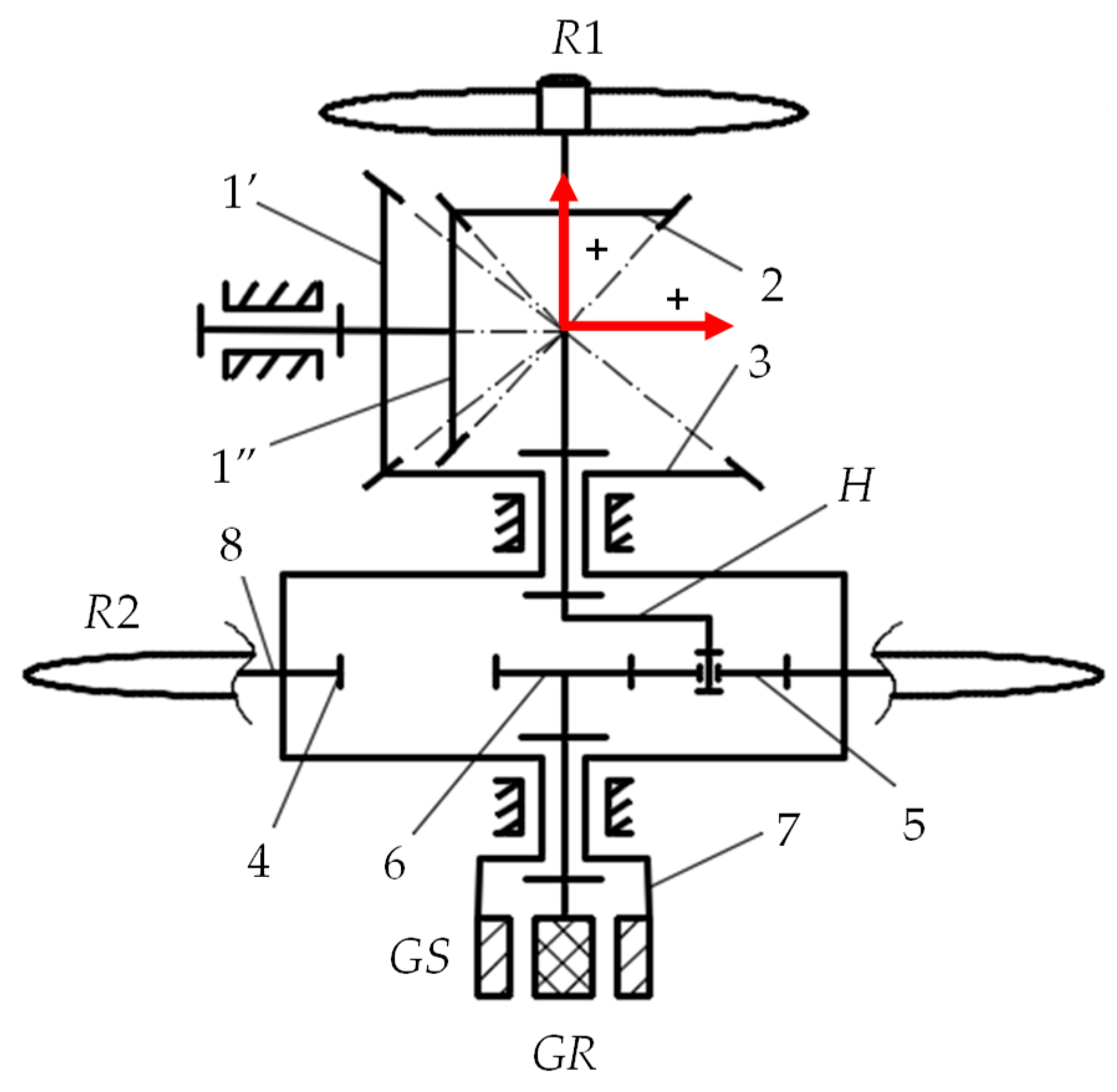
Considering the general case illustrated in Figure 1, the paper highlights the performance and features of this new type of WTs through an example that integrates a new planetary speed increaser (Figure 2), which is subject to patent application. This speed increaser is obtained by linking in parallel a bevel transmission with fixed axes 2–1”−1’−3 (denoted by I, Figure 3) and a 2 DOF planetary spur gear set with one satellite gear 4-5-6-H (denoted by II). The bevel gear 3 transmits the motion to the sun ring gear 4, which is connected to the generator stator GS, while the carrier H takes the motion from the main wind rotor R1. The secondary wind rotor R2 drives the ring gear 4 and, thus, the stator GS. The shaft of the rotor GR is connected to the shaft of the sun gear 6 in the planetary gear set II.
The component transmissions, the internal and external links of the planetary speed increaser and the torques on the WT shafts are presented in the block scheme depicted in Figure 3, which is associated with the conceptual scheme illustrated in Figure 2.
The kinematic and static transmission functions of the speed increaser can be determined on the basis of the kinematic and static equations (correlations), which characterize the isolated transmissions I and II, and the internal and external links according to the block scheme in Figure 3 [18,21,23]:
- The correlations for the input shafts:
- The correlations for the output shafts:
- The correlations for the bevel mechanism with fixed axes I:for , and , while is the interior efficiency of transmission I, and are the efficiencies of the two component bevel gear pairs, zi—the teeth number of the component gears, i = 1’, 1″, 2, 3.
- The correlations for the connections between the planetary gear set II and the bevel transmission I:
- The correlations for the external links:where represents the speed of the equivalent electric generator.
Based on the previous correlations, the kinematic and static modeling of the proposed planetary gearbox (Figure 2) is further presented, along with the power flow and efficiency analysis for four functioning cases of the speed increaser, defined according to the input torques ratio: (a) , (b) (c) , (d) . The torque generated by a wind rotor can be controlled by adjusting the pitch angle of the blades, which is considered in the paper through the adjustable parameter .
3. Kinematic Modeling
The aim of the kinematic modeling is to find out the kinematic transmitting functions of the speed increaser by considering the power flows from inputs to outputs and based on the equations that characterize both the isolated transmissions and the internal and external links, according to the block scheme in Figure 3.
The speed transmitting function from the main wind rotor R1 to the generator rotor GR can be expressed by:
where is the amplification kinematic ratio for the main power flow; wind rotor R1—generator rotor GR, based on the following speed relations:
The speed transmitting function and the amplification kinematic ratio on the power flow; main wind rotor R1—generator stator GS, can be obtained:
Similarly, the speed transmitting function from the secondary wind rotor R2 to the generator rotor GR can be derived as follows:
where is the amplification kinematic ratio for the secondary power flow; wind rotor R2—generator rotor GR. The angular speed of the generator stator GS in relation with the secondary wind rotor R2 speed can be also established:
Therefore, the kinematic parameters that characterize the two power flows from the wind rotors to the equivalent electric generator are expressed by:
for the main flow, and:
for the secondary flow.
4. Modeling of Torques and Efficiency
The efficiency of the speed increaser depends on the efficiency values of the two component transmissions, being influenced by the power flows and the torques on each branch, according to the kt ratio. By considering the block scheme in Figure 3, the speed increaser efficiency can be obtained on the basis of the following algorithm:
1. The torques transmitting function for the main power flow R1-eg is established by:
where the torques T3 and TH are given by:
Therefore, the torque TR1 can be expressed as follows:
2. The torques transmitting function for the secondary power flow R2-eg is established by the following relation:
3. The speed increaser efficiency is further determined:
5. Numerical Simulations and Interpretation
Based on the previous analytical relations, some relevant numerical results regarding the influence of the amplification kinematic ratio iaR1_eg and the kt ratio on the main kinematic and static parameters, on the transmission efficiency and output power, as well as on the power flow through the speed increaser are further presented.
The numerical simulations are focused on three main functional aspects:
- (a)
- The correlative influence of the amplification kinematic ratio iaR1_eg and the kt ratio on the speed increaser efficiency; in this regard, a unitary input power at the main wind rotor is used, e.g., PR1 = 1 kW ( ).
- (b)
- The power flow distinct cases depending on the kt ratio values, for a particular value of the kinematic ratio, i.e., iaR1_eg = 18: four functional cases are identified, and detailed in the subchapter 5.2 under the assumptions of considering and neglecting the friction in the gear pairs.
- (c)
- The operating point of the wind system for the previous four functional cases.
A numerical example of the planetary speed increaser characterized by , and are further considered as basic solution in all the performed simulations. The variation of the amplification kinematic ratio iaR1_eg, dependent on both the interior kinematic ratios of the transmissions I and II, is analyzed in this paper only by changing the kinematic ratio of the bevel transmission and by maintaining the kinematic ratio at a constant value (). Several scenarios of adjusting the torque generated by the secondary wind rotor (i.e., the ratio) are discussed, considering that the speed increaser has a closed loop power flow. The power flow and the operating point simulations are carried out for .
5.1. The Influence of the Amplification Kinematic Ratio and the Input Torques Ratio
The amplification kinematic ratio of the main power flow depends on the interior kinematic ratios and , according to rel. (27), and it can significantly influence the speed increaser efficiency for different values of the input toques ratio . Thus, starting from the basic speed increaser solution, a variation of the amplification kinematic ratio (Figure 4) is obtained by changing the value of the interior kinematic ratio in the range . These results highlight the following properties of the speed increaser:
- -
- the efficiency does not depend on the ratio in the case kt = 1, i.e., the input torques TR1 and TR2 are equal in absolute value, the efficiency being at its maximum value , Figure 4a,b;
- -
- for lower values of the kt parameter (kt < 0.1), the efficiency decreases continuously with the increase of the amplification kinematic ratio, Figure 4b; the efficiency has a growing trend for higher subunit values (0.1 < kt < 1) and in the range of high values of the amplification ratio, Figure 4b;
- -
- if the secondary wind rotor generates higher torques than the main rotor, |TR2| > TR1 (i.e., kt > 1), the efficiency increases continuously with the increase of the amplification kinematic ratio (Figure 4b, kt = 1.2).
The results of the numerical simulations for different values of the kt ratio in the case of the basic solution (, ) are presented in Figure 5; accordingly, the following conclusions can be drawn:
- -
- the transmission efficiency increases with the increase of the kt ratio until the secondary wind rotor torque becomes equal to that of the main rotor (kt = 1), after which it decreases continuously with the increase of kt ratio, regardless of the value of the amplification ratio (Figure 5a,b);
- -
- the useful mechanical power Peg at the equivalent generator input has a linear variation with respect to kt (Figure 5c,d), being directly dependent on the power introduced in the system by the secondary wind rotor R2.
Therefore, this type of wind turbine can be designed to function with high amplification kinematic ratios and efficiency, mainly when the input torques ratio kt is maintained around the unitary value.
5.2. Power Flow
Power transmitting from inputs to outputs can be done in an open or closed loop flow according to the kt values, the power flow configuration also influencing the speed increaser efficiency. For equal torques of the two wind rotors (kt = 1), the power transmitted by the bevel transmission I becomes null (i.e., ) and, therefore, it represents the limit value at which the change of the power flow direction through this transmission occurs.
Considering the basic solution of the planetary speed increaser ( , ), the power flows without friction (Figure 6) and with friction (Figure 7) are analyzed in four distinct functional cases depending on the value of the kt ratio:
- Case 1: the torque of the secondary wind rotor is null , i.e., , Figure 6a and Figure 7a. This situation occurs when the secondary wind turbine is set so as not to generate mechanical power, the gearbox thus running with one input and two outputs at the efficiency value , in case of considering friction (Figure 7a);
- Case 2: , Figure 6b and Figure 7b. In this situation, the bevel transmission I is no longer involved in the mechanical power transmitting and, thus, decoupling of the two power inputs occurs: the power generated by the main wind rotor R1 is entirely transmitted to the generator rotor GR, the secondary wind rotor R2 ensures the power requirements for the generator stator GS, and the power difference is transmitted to the GR rotor. In this case, the gearbox efficiency becomes , Figure 7b.
- Case 3: , Figure 6c and Figure 7c. The power of the main wind rotor R1 branches through the two transmissions I and II, the flow through the bevel mechanism I merges with the power flow of the wind rotor R2, which is then distributed to the generator stator GS and to the generator rotor GR. In this case, for a power of the R2 rotor equal to 0.5 of the R1 rotor power; according to Figure 7c, a gearbox efficiency of is obtained.
- Case 4: , Figure 6d and Figure 7d. In this case, the power generated by the secondary wind rotor R2 is transmitted in a branched way to the stator GS and to the rotor GR by both transmissions I and II. As a result, the power flow through the transmission I is reversed with respect to case 3, a part of the power generated by the secondary wind rotor R2 being summed up with that of the main rotor R1 and then transmitted to the generator rotor GR through the planetary gear set II. For the numerical example, the planetary transmission efficiency is , Figure 7d.
According to the numerical example, the planetary gearbox operates with higher efficiency for values of the secondary wind rotor torques around the limit value which corresponds to close values of the two input torques. In the particular case , the torque transmitted by the bevel transmission I becomes null and, therefore, it has the role of a kinematic mechanism.
5.3. Operating Point
The stationary operating point of a wind system of the type: two CRWR-1 DOF speed increaser-CREG, Figure 1 and Figure 2, can be determined if the transmitting functions of the speed increaser are known: three kinematic functions, relations (17), (20), and (24) and 1 function for torques, relation (33), the mechanical characteristics of the two wind rotors and the mechanical characteristic of the equivalent electric generator. The equality relation in absolute value between the torques of the rotor GR and the stator GS, according to Equation (16), is added to the previous seven independent equations. The values of the eight kinematic and static external parameters, associated to the four external links described in Figure 3, which present the operating point in the WT steady-state regime, can be obtained from these eight equations.
The hypothesis of linear mechanical characteristics for both wind rotors and the equivalent electric generator is considered in this paper—a situation encountered in practice at direct current (DC) electric generators.
Considering that the torque of the secondary wind rotor and, implicitly, its mechanical characteristics can be adjusted through the kt ratio, the calculation of the operating point will be further exemplified in four representative cases kt = [0; 0.5; 1; 1.4].
The mechanical characteristics of wind rotors can be expressed as follows:
and can be reduced to the equivalent output shaft (es) of the speed increaser (the shaft 6 ≡ GR having the torque unmodified, and the speed equal to the relative speed between the rotor and the stator of the electric generator), obtaining a linear equation of the type:
where , , , and are constant coefficients and . Note that the interior kinematic ratios of the speed increaser ( and ) are known, and the coefficients , , , and depend on the kt ratio.
Considering the relation of derived from rel. (1) and (26):
the expression is obtained:
where
The coefficients of the mechanical characteristics of the two wind rotors R1 and R2, reduced to the output equivalent shaft es of the speed increaser are obtained according to Equations (37) and (39):
Knowing the mechanical characteristic of the equivalent electric generator:
where aeg and beg are constant coefficients, the operating point of the wind turbine in steady-state regime can be obtained by solving the following system:
The coordinates of the operating point on the equivalent output shaft (, ) are thus obtained:
The values of all kinematic and static, external and internal parameters of the wind system can be further determined by means of the numerical values of the coordinates , calculated with the relations (44) and (45).
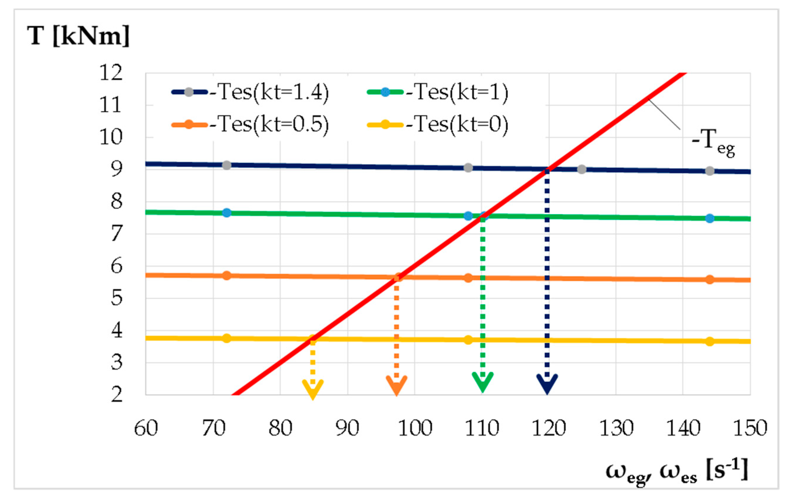
For a numerical case of the wind turbine type presented in Figure 2, the values of the constant parameters and of the operating point coordinates are tabulated (see Table 2 below) for four values of the kt ratio. The operation point parameters can be graphically obtained by reducing the mechanical characteristics of the two wind rotors to the equivalent output shaft es (Figure 8).
The results obtained by simulating the operating point also highlight the possibility of increasing the mechanical power at the generator input by increasing the kt ratio, Figure 8. The optimal wind turbine operation (i.e., with maximum efficiency) is achieved for torques of the secondary wind rotor R2 adjusted to quasi-equal values of the main wind rotor R1 torques (i.e., kt ≈ 1), Table 2.
6. Conclusions
The performance of a new, patent-pending solution of a 1 DOF planetary transmission is analyzed in this paper, meant to increase the speeds and torques in the counter-rotating wind turbines with counter-rotating electric generator. The speed increaser is obtained by parallel connection of a two-step bevel transmission with a 2 DOF planetary gear set. This example was used to explain the proposed kinematic and static modeling algorithm that allows identifying the speed increaser efficiency and performance of the wind turbine which integrates this type of gearbox, by solving the stationary operating point problem.
Using the properties of 1 DOF transmissions with two inputs and two outputs of summing up the torques/powers and distributing an external speed in a determined way, the proposed transmission allows both an increase in the relative speed between the electric generator rotor and stator, and additional power/torque input brought by the secondary wind turbine.
Beyond the advantage of increasing power, the use of these wind turbines with counter-rotating components allows a more efficient operation of the electric generator by providing increased speeds along with a compact design. The results presented in the form of kinematic and static computing methodology, analytical models, and diagrams developed for various case studies may prove useful for researchers and designers in the field to establish advantageous solutions of planetary speed increasers for counter-rotating wind turbines that integrate electric generators with mobile stators in which speed needs to be increased proportionally with the power increase.
Author Contributions
Conceptualization, M.N., R.S. and C.J.; methodology, M.N., R.S. and C.J.; software, M.N., R.S. and C.J.; validation, M.N., R.S. and C.J.; formal analysis, M.N. and R.S.; investigation, M.N., R.S. and C.J.; resources, M.N., R.S. and C.J.; data curation, M.N., R.S. and C.J.; writing-original draft preparation, M.N., R.S. and C.J.; writing—review and editing, M.N.; visualization, M.N., R.S. and C.J.; supervision, M.N.; project administration, M.N.
Funding
This research received no external funding.
Conflicts of Interest
The authors declare no conflict of interest.
Nomenclature
| WT | Wind turbine | DOF | Degree of freedom |
| CRWT | Counter-rotating wind turbine | M | Mechanism degree of freedom |
| CRWR | Counter-rotating wind rotors | GR | Electric generator rotor |
| CREG | Counter-rotating electric generator | GS | Electric generator stator |
| R1 | Main wind rotor | L | Number of mechanism inputs and outputs |
| R2 | Secondary wind rotor | eg | Equivalent electric generator |
| SI | Speed Increaser | ia | Amplification kinematic ratio |
| ω | Angular speed | η0 | Transmission interior efficiency |
| T | Torque | i0 | Transmission interior kinematic ratio |
| kt | Input torques ratio | ηtot | Efficiency of the speed increaser |
| z | Gear teeth number | es | Equivalent output shaft of the transmission |
| H | Planetary carrier | PR1,2 | Power of the wind rotor R1,2 |
References
- Booker, J.D.; Mellor, P.H.; Wrobel, R.; Drury, D. A compact, high efficiency contra-rotating generator suitable for wind turbines in the urban environment. Renew. Energy 2010, 35, 2027–2033. [Google Scholar] [CrossRef]
- Sapre, R.; Murkute, H.; Agrawal, R. Comparison between single axis wind turbine and counter wind turbine—A case study. Glob. J. Eng. Appl. Sci. 2012, 2, 144–146. [Google Scholar]
- Vișa, I.; Jaliu, C.; Duta, A.; Neagoe, M.; Comsit, M.; Moldovan, M.; Ciobanu, D.; Burduhos, B.; Saulescu, R. The Role of Mechanisms in Sustainable Energy Systems; Transilvania University of Brașov Publishing House: Brașov, Romania, 2015; pp. 281–316. ISBN 978-606-19-0571-3. [Google Scholar]
- Appa, K. Energy Innovations Small Grant (EISG) Program (Counter Rotating Wind Turbine System); EISG Final Report; EISG: Shores, CA, US, 2002; Available online: http://www.eai.in/ref/invent/upload/00-09%2520FAR%2520Appendix%2520A.pdf (accessed on 11 June 2017).
- Jung, S.; No, T.; Ryu, K. Aerodynamic performance prediction of a 30kW counter-rotating wind turbine system. Renew. Energy 2005, 30, 631–644. [Google Scholar] [CrossRef]
- McKenna, R.; Leye, P.O.; Fichtner, W. Key challenges and prospects for large wind turbines. Renew. Sustain. Energy Rev. 2016, 53, 1212–1221. [Google Scholar] [CrossRef]
- Lee, S.; Kim, H.; Lee, S. Analysis of aerodynamic characteristics on a counter-rotating wind turbine. Curr. Appl. Phys. 2010, 10, S339–S342. [Google Scholar] [CrossRef]
- Hwang, B.; Lee, S.; Lee, S. Optimization of a counter-rotating wind turbine using the blade element and momentum theory. J. Renew. Sustain. Energy 2013, 5, 052013. [Google Scholar] [CrossRef]
- Lee, S.; Kim, H.; Son, E.; Lee, S. Effects of design parameters on aerodynamic performance of a counter-rotating wind turbine. Renew. Energy 2012, 42, 140–144. [Google Scholar] [CrossRef]
- Didane, D.H.; Rosly, N.; Zulkafli, M.F.; Shamsudin, S.S. Performance evaluation of a novel vertical axis wind turbine with coaxial contra-rotating concept. Renew. Energy 2015, 115, 353–361. [Google Scholar] [CrossRef]
- Shin, C. Multi-Unit Rotor Blade System Integrated Wind Turbine. U.S. Patent No 5876181, 2 March 1999. [Google Scholar]
- Climescu, O.; Saulescu, R.; Jaliu, C. Specific features of a counter-rotating transmission for renewable energy systems. Environ. Eng. Manag. J. 2011, 10, 1105–1113. [Google Scholar] [CrossRef]
- Oprina, G.; Chihaia, R.A.; El-Leathey, L.A.; Nicolaie, S.; Băbuțanu, C.A.; Voina, A. A review on counter-rotating wind turbines development. J. Sustain. Energy 2016, 7, 91–98. [Google Scholar]
- Marjanovic, N.; Isailovic, B.; Marjanovic, V.; Milojevic, Z.; Blagojevic, M.; Bojic, M. A practical approach to the optimization of gear trains with spur gears. Mech. Mach. Theory 2012, 53, 1–16. [Google Scholar] [CrossRef]
- Bevington, C.M.; Bywaters, G.L.; Coleman, C.C.; Costin, D.P.; Danforth, W.L.; Lynch, J.A.; Rolland, R.H. Wind Turbine Having a Direct-Drive Drivetrain. U.S. Patent 7431567B1, 7 October 2008. [Google Scholar]
- Climescu, O.; Jaliu, C.; Saulescu, R. Comparative Analysis of Horizontal Small Scale Wind Turbines for a Specific Application. In Proceedings of the 14th IFToMM World Congress, Taipei, Taiwan, 25–30 October 2015. [Google Scholar] [CrossRef]
- Mesquita, A.L.A.; Palheta, F.C.; Pinheiro Vaz, J.R.; Girão de Morais, M.V.; Gonçalves, C. A methodology for the transient behavior of horizontal axis hydrokinetic turbines. Energy Convers. Manag. 2014, 87, 1261–1268. [Google Scholar] [CrossRef]
- Neagoe, M.; Saulescu, R.; Jaliu, C.; Cretescu, N. Novel Speed increaser used in counter-rotating wind turbines. In New Advances in Mechanisms, Mechanical Transmissions and Robotics, Mechanisms and Machine Science 46; Springer: Berlin, Germany, 2017; pp. 143–151. [Google Scholar]
- Saulescu, R.; Neagoe, M.; Jaliu, C. Improving the Energy Performance of Wind Turbines Implemented in the Built Environment Using Counter-Rotating Planetary Transmissions; Materials Science and Engineering—IOP Conference Series: Materials Science and Engineering; IOP Publishing Ltd.: Bristol, UK, 2016. [Google Scholar]
- Saulescu, R.; Neagoe, M.; Munteanu, O.; Cretescu, N. Performance Analysis of a Novel Planetary Speed Increaser Used in Single-Rotor Wind Turbines with Counter-Rotating Electric Generator; Materials Science and Engineering—IOP Conference Series: Materials Science and Engineering; IOP Publishing Ltd.: Bristol, UK, 2016. [Google Scholar]
- Saulescu, R.; Jaliu, C.; Neagoe, M. Structural and Kinematic Features of a 2 DOF Speed Increaser for Renewable Energy Systems. Appl. Mech. Mater. 2016, 823, 367–372. [Google Scholar] [CrossRef]
- Saulescu, R.; Neagoe, M.; Jaliu, C.; Munteanu, O. Comparative analysis of two wind turbines with planetary speed increaser in steady-state. Appl. Mech. Mater. 2016, 823, 355–360. [Google Scholar] [CrossRef]
- Saulescu, R.; Jaliu, C.; Munteanu, O.; Climescu, O. Planetary Gear for Counter-rotating Wind Turbines. Appl. Mech. Mater. 2014, 658, 135–140. [Google Scholar] [CrossRef]
- Saulescu, R.; Jaliu, C.; Climescu, O.; Diaconescu, D. On the use of 2 DOF planetary gears as “speed increaser” in small hydros and wind turbines. In Proceedings of the ASME 2011 International Design Engineering Technical Conferences & Computers and Information in Engineering Conference, Washington DC, USA, 25–31 August 2011. [Google Scholar]
- Wacinski, A.; Sàrl, E. Drive Device for a Windmill Provided with Two Counter–Rotative Propellers. U.S. Patent No. 7384239, 10 June 2008. [Google Scholar]
- Herzog, R.; Schaffarczyk, A.P.; Wacinski, A.; Zürcher, O. Performance and stability of a counter–rotating windmill using a planetary gearing: Measurements and Simulation. In Proceedings of the European Wind Energy Conference & Exhibition, Warsaw, Poland, 20–23 April 2010; Available online: https://www.researchgate.net/publication/236683548 (accessed on 15 June 2017).
- Brander, M. Bi-Directional Wind Turbine. U.S. Patent 2008/0197639 A1, 23 March 2008. [Google Scholar]
- Qiu, J.; Liu, B.; Dong, H.; Wang, D. Type Synthesis of Gear-box in Wind Turbine. Procedia Comput. Sci. C 2017, 109, 809–816. [Google Scholar] [CrossRef]
- Hall, J.F.; Mecklenborg, C.A.; Chen, D.; Pratap, S.B. Wind energy conversion with a variable-ratio gearbox: Design and analysis. Renew. Energy 2011, 36, 1075–1080. [Google Scholar] [CrossRef]
- Vidal, Y.; Acho, L.; Luo, N.; Zapateiro, M.; Pozo, F. Power Control Design for Variable-Speed Wind Turbines. Energies 2012, 5, 3033–3050. [Google Scholar] [CrossRef] [Green Version]
- Zhamalov, A.Z.; Obozov, A.D.; Kunelbaev, M.M.; Baikadamova, L.S. Capacity and Power Characteristics of Disk Generator with Counter-Rotation of Double-Rotor Wind Turbine. Middle-East J. Sci. Res. 2013, 15, 1655–1662. [Google Scholar] [CrossRef]
- Saulescu, R.; Neagoe, M.; Jaliu, C. Conceptual Synthesis of Speed Increasers for Wind Turbine Conversion Systems. Energies 2018, 11, 2257. [Google Scholar] [CrossRef]
- Newman, B.G. Actuator-disc theory for vertical-axis wind turbines. J. Wind Eng. Ind. Aerodyn. 1983, 15, 347–355. [Google Scholar] [CrossRef]
- Farahani, E.M.; Hosseinzadeh, N.; Ektesabi, M. Comparison of fault-ride-through capability of dual and single-rotor wind turbines. Renew. Energy 2012, 48, 473–481. [Google Scholar] [CrossRef]
- No, T.S.; Kim, J.E.; Moon, J.H.; Kim, S.J. Modelling, control, and simulation of dual rotor wind turbine generator system. Renew. Energy 2009, 34, 2124–2132. [Google Scholar] [CrossRef]
- Kubo, K.; Hano, Y.; Mitarai, H.; Hirano, K.; Kanemoto, T.; Galal, A.M. Intelligent wind turbine unit with tandem rotors (discussion of prototype performances in field tests). Curr. Appl. Phys. 2010, 10, S326–S331. [Google Scholar] [CrossRef]
- Chantharasenawong, C.; Suwantragul, B.; Ruangwiset, A. Axial Momentum Theory for Turbines with Co-axial Counter Rotating Rotors. In Proceedings of the Commemorative International Conference of the Occasion of the 4th Cycle Anniversary of KMUTT Sustainable Development to Save the Earth: Technologies and Strategies Vision 2050: (SDSE2008), Bangkok, Thailand, 11–13 December 2008. [Google Scholar]
- Kanemoto, T.; Galal, A.M. Development of intelligent wind turbine generator with tandem wind rotors and double rotational armatures. JSME Int. J. Ser. B 2006, 49, 450–457. [Google Scholar] [CrossRef]
- Caiozza, J. Wind Driven Electric Generator Apparatus. U.S. Patent 7227276 B2, 5 June 2007. [Google Scholar]
- Winderl, W. Wind Operated Generator. U.S. Patent 4039848, 2 August 1977. [Google Scholar]
- Duong, M.Q.; Leva, S.; Mussetta, M.; Le, K.H. A Comparative Study on Controllers for Improving Transient Stability of DFIG Wind Turbines During Large Disturbances. Energies 2018, 11, 480. [Google Scholar] [CrossRef]
- Duong, M.Q.; Grimaccia, F.; Leva, S.; Mussetta, M.; Le, K.H. Improving Transient Stability in a Grid-Connected Squirrel-Cage Induction Generator Wind Turbine System Using a Fuzzy Logic Controller. Energies 2015, 8, 6328–6349. [Google Scholar] [CrossRef] [Green Version]
- Barambones, O. Sliding Mode Control Strategy for Wind Turbine Power Maximization. Energies 2012, 5, 2310–2330. [Google Scholar] [CrossRef] [Green Version]
- Zhu, Y.; Cheng, M.; Hua, W.; Wang, W. A Novel Maximum Power Point Tracking Control for Permanent Magnet Direct Drive Wind Energy Conversion Systems. Energies 2012, 5, 1398–1412. [Google Scholar] [CrossRef] [Green Version]
- Hau, E. Wind Turbines: Fundamentals, Technologies, Application, Economics, 2nd ed.; Springer: Berlin/Heidelberg, Germany, 2006; pp. 253–3018. ISBN 978-3-540-24240-6. [Google Scholar]
- Jelaska, D.; Podrug, S.; Perkusic, M. A novel hybrid transmission for variable speed wind turbines. Renew. Energy 2015, 83, 78–84. [Google Scholar] [CrossRef]
- Zhao, M.; Ji, J. Dynamic analysis of wind turbine gearbox components. Energies 2016, 9, 110. [Google Scholar] [CrossRef]
- Moghadassian, B.; Rosenberg, A.; Sharma, A. Numerical Investigation of Aerodynamic Performance and Loads of a Novel Dual Rotor Wind Turbine. Energies 2016, 9, 571. [Google Scholar] [CrossRef]
- Sultan, T.; Gour, A.; Mukeshpandey. Differentiation analysis of single and dual rotor wind turbine torque transmission system. Int. J. Mech. Eng. Robot. Res. 2014, 3, 585–588. [Google Scholar]
- Marugán, A.P.; Márquez, F.P.G.; Perez, J.M.P.; Ruiz-Hernández, D. A survey of artificial neural network in wind energy systems. Appl. Energy 2018, 228, 1822. [Google Scholar] [CrossRef]
Figure 1.
Counter-rotating wind turbine with counter-rotating electric generator: (a) general conceptual scheme; (b) block scheme of the speed increaser (SI) with two inputs and two outputs (R1—main wind rotor, R2—secondary wind rotor, GR—electric generator rotor, GS—electric generator stator, L—number of mechanism inputs and outputs, M—mechanism degree of freedom).

Figure 2.
The conceptual scheme of a wind system containing: two counter-rotating wind rotors, a 1 degree of freedom (DOF) speed increaser and a counter-rotating electric generator.
Figure 2.
The conceptual scheme of a wind system containing: two counter-rotating wind rotors, a 1 degree of freedom (DOF) speed increaser and a counter-rotating electric generator.

Figure 3.
The block scheme of the 1 DOF planetary speed increaser.
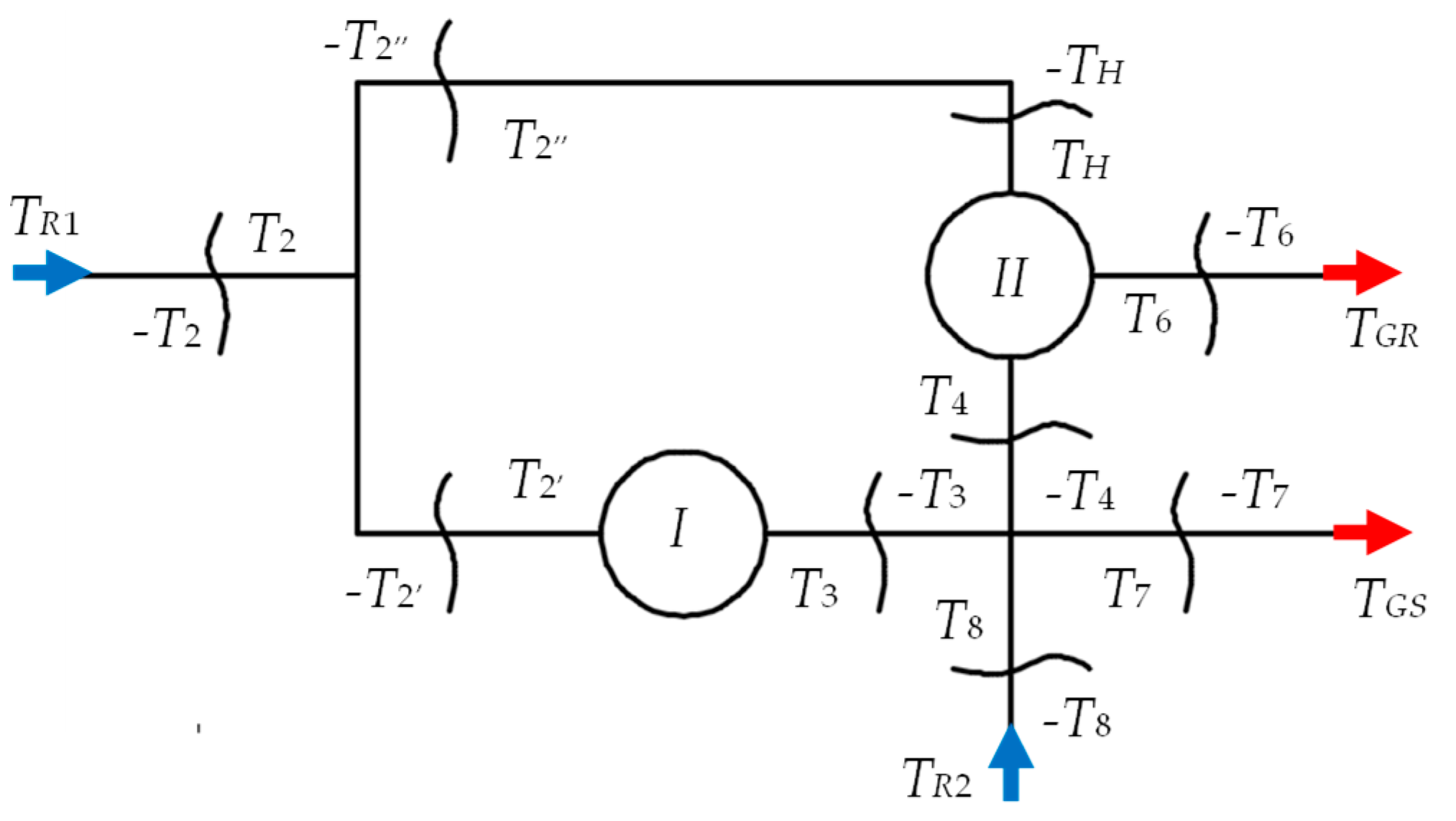
Figure 4.
The variation of the speed increaser efficiency as a function of the amplification kinematic ratio: (a) for three representative values of the kt ratio; (b) for kt ≤ 1.2.
Figure 4.
The variation of the speed increaser efficiency as a function of the amplification kinematic ratio: (a) for three representative values of the kt ratio; (b) for kt ≤ 1.2.

Figure 5.
The influence of the kt ratio on the speed increaser efficiency and on the output power Peg: (a) the TR2 torque and ηtot efficiency variations; (b) the ηtotefficiency variation around the maximum value for different values of the iaR1-eg ratio; (c) the power Peg variation; (d) the powers and efficiency variations for kt < 2.5.
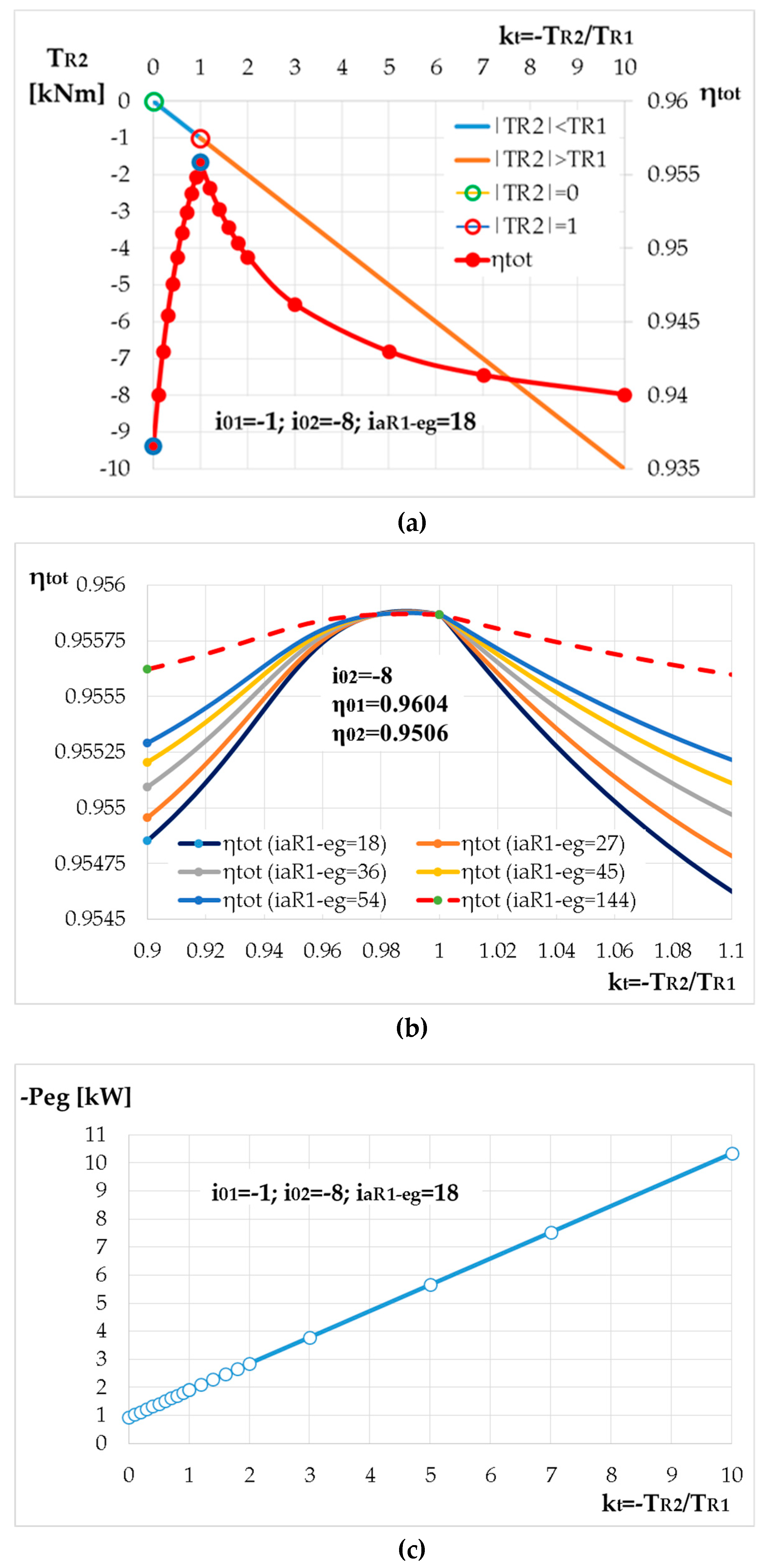
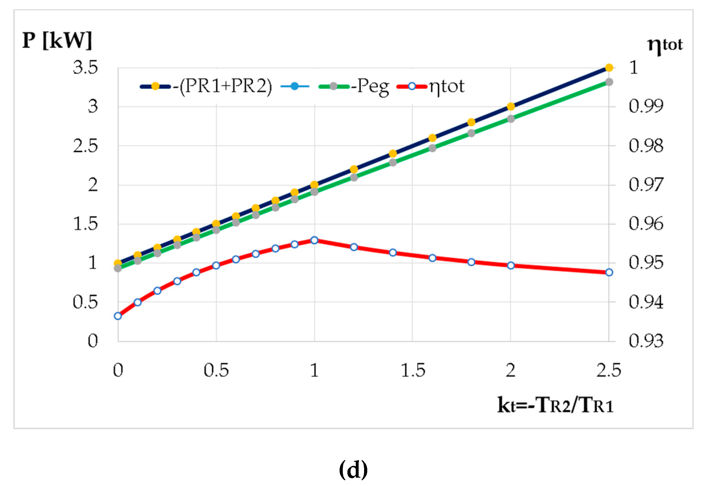
Figure 6.
Power flow in the premise of neglecting friction for the case: (a) kt = 0; (b) kt = 1, (c) 0 < kt < 1; (d) kt ≥ 1.
Figure 6.
Power flow in the premise of neglecting friction for the case: (a) kt = 0; (b) kt = 1, (c) 0 < kt < 1; (d) kt ≥ 1.

Figure 7.
Power flow in the premise of considering friction for the case: (a) kt = 0; (b) kt = 1; (c) kt = 0.5 (< 1); (d) kt = 1.4 (> 1).
Figure 7.
Power flow in the premise of considering friction for the case: (a) kt = 0; (b) kt = 1; (c) kt = 0.5 (< 1); (d) kt = 1.4 (> 1).
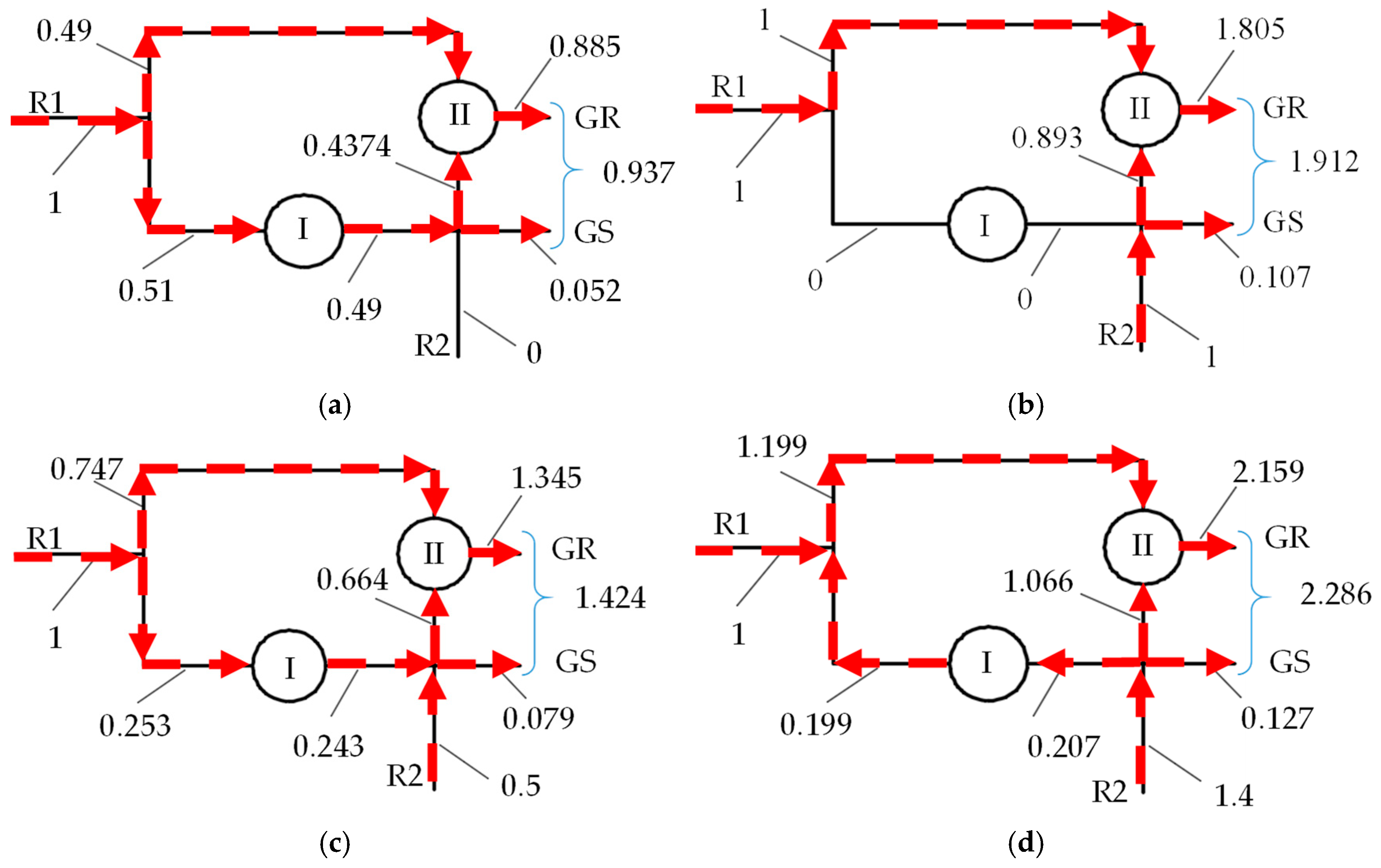
Figure 8.
Graphical determination of the running point parameters on the equivalent output shaft for the four analyzed cases (kt = 0; 0.5; 1; 1.4).
Figure 8.
Graphical determination of the running point parameters on the equivalent output shaft for the four analyzed cases (kt = 0; 0.5; 1; 1.4).

Table 1.
The relations for the kinematic and static parameters as functions of the input parameters (ωR1, TR1).
Table 1.
The relations for the kinematic and static parameters as functions of the input parameters (ωR1, TR1).
| Remark: the relations are valid for . For , has to be replaced by . | |||||
Table 2.
Functional parameters of the wind turbine in steady-state regime.
| WT Component | Constant Parameters | Variable Parameters | kt | |||
|---|---|---|---|---|---|---|
| 0 | 0.5 | 1 | 1.4 | |||
| Main wind rotor R1 | = 0.386 kNms = 73.5 kNm | [s−1] | 4.71 | 5.42 | 6.13 | 6.94 |
| [kNm] | 71.68 | 71.40 | 71.13 | 70.82 | ||
| [kW] | 337.61 | 386.99 | 436.03 | 491.49 | ||
| Secondary wind rotor R2 | [s−1] | 0 | −5.42 | −6.13 | −6.94 | |
| [kNm] | 0 | −35.70 | −71.13 | −99.15 | ||
| [kW] | 0 | 193.49 | 436.03 | 688.10 | ||
| Speed increaser | = 18 | 0.9366 | 0.9494 | 0.9559 | 0.9171 | |
| Equivalent output shaft | [kNms] | −0.0011 | −0.0017 | −0.0023 | −0.0027 | |
| [kNm] | −3.8243 | −5.8153 | −7.8063 | −9.3360 | ||
| Equivalent electric generator | aeg = 0.15 kNms beg = 9 kNm | eg [s−1] | 84.77 | 97.54 | 110.41 | 120.07 |
| Teg [kNm] | −3.73 | −5.65 | −7.55 | −9.01 | ||
| Peg [kW] | −316.21 | −551.11 | −833.60 | −1081.80 | ||
© 2019 by the authors. Licensee MDPI, Basel, Switzerland. This article is an open access article distributed under the terms and conditions of the Creative Commons Attribution (CC BY) license (http://creativecommons.org/licenses/by/4.0/).
Share and Cite
MDPI and ACS Style
Neagoe, M.; Saulescu, R.; Jaliu, C. Design and Simulation of a 1 DOF Planetary Speed Increaser for Counter-Rotating Wind Turbines with Counter-Rotating Electric Generators. Energies 2019, 12, 1754. https://doi.org/10.3390/en12091754
AMA Style
Neagoe M, Saulescu R, Jaliu C. Design and Simulation of a 1 DOF Planetary Speed Increaser for Counter-Rotating Wind Turbines with Counter-Rotating Electric Generators. Energies. 2019; 12(9):1754. https://doi.org/10.3390/en12091754
Chicago/Turabian StyleNeagoe, Mircea, Radu Saulescu, and Codruta Jaliu. 2019. "Design and Simulation of a 1 DOF Planetary Speed Increaser for Counter-Rotating Wind Turbines with Counter-Rotating Electric Generators" Energies 12, no. 9: 1754. https://doi.org/10.3390/en12091754
Note that from the first issue of 2016, this journal uses article numbers instead of page numbers. See further details here.