A Model-Based Design of Distributed Automation Systems for the Smart Grid: Implementation and Validation


1
Networks and Systems Operation Department, Unareti S.p.A, 25124 Brescia, Italy
2
Digital Energy Department, Schneider Electric, 41092 Seville, Spain
*
Author to whom correspondence should be addressed.
Energies 2020, 13(14), 3560; https://doi.org/10.3390/en13143560
Submission received: 22 May 2020
/
Revised: 18 June 2020
/
Accepted: 6 July 2020
/
Published: 10 July 2020
(This article belongs to the Special Issue Energy Management System for Smart Grids)
Abstract
:The paper aims at describing a model-based approach to design automation logics for fault location and supply restoration in medium voltage distribution networks. The application of automation functions along medium voltage feeders and, in particular, the installation of protection devices in secondary substations mandates the design and the implementation of complex logics to coordinate the operations of this hardware in case of fault occurrences. This synchronization is realized with the exchange of IEC 61850 GOOSE messages, but the correct usage of this information must be implemented in each protection device through dedicated logics, which are not in the common out-of-the-box system configurations. To support the introduction and the design of these logics, an automata-based approach has been proposed and successfully demonstrated in a real environment in the European research project IDE4L. This formal methodology has been introduced to simplify the design phase and to standardize the logics implemented in the protection prototypes realized in the project. The same models have also been used in the implementation phase with a semi-automatic code generation procedure, considering as a target system the software programmable logic controllers (soft-PLCs), available on the protection devices. Based on the test results and the short time to set up the test bench, this approach proved to be a reliable and effective way to implement complex medium voltage (MV) automation logics such those needed in modern smart grids.
1. Introduction
In the electricity supply chain, the distribution system operator (DSO) is the player in charge of operating the electricity grid and of ensuring that it operates within regulatory parameters. The distribution grid starts from the edge of the high voltage (HV) transmission network with HV/MV transformer substations, and it includes the medium voltage (MV) network, MV/LV substations and the low voltage (LV) grid up to the final customers. Among the most common tasks of a DSO, fault management is one of the most important. The distribution grid is a dependable infrastructure; therefore, many regulatory frameworks relate the quality of service to a premium/penalty mechanism directly influencing DSO incomes. The two common indicators used to measure the quality of service are the System Average Interruption Frequency Index (SAIFI) and the System Average Interruption Duration Index (SAIDI) [1].
To optimize these indicators, DSOs are enhancing their automation systems, which have been—so far—mainly confined to the HV/MV substations. Indeed, in the traditional configuration of the automation system, the only element able to determine the fault is the intelligent electronic device (IED), usually located at the beginning of the MV line. This device—containing the so-called protection functions (PFs)—determines the presence of a fault on the MV network and opens a breaker—which is the power equipment able to interrupt the current flow, even during the extreme conditions occurring during a fault—in order to avoid permanent damage to power assets. This could result in a very large de-energized area, with all customers belonging to the opened feeder affected by the voltage interruption and with a significant impact on the continuity of the service indicators.
Several approaches have been proposed in the past to improve this condition [2,3,4,5,6]. One of the most prominent solutions consists of limiting the de-energized area as close as possible to the source of the fault, i.e., to be “selective” with respect to its position. This can be obtained by placing a protection device and a breaker in a selected number of MV/LV substations. The actions of the IEDs placed in different locations must be coordinated in order to avoid multiple breaker openings, which may lead to an even worse scenario. This coordination approach between IEDs installed in different locations is called logic selectivity [7,8]. Logic selectivity sets severe constraints on the communication network, as analyzed in [9,10].
All these automatisms also have to take into consideration the fact that human operators in the control center of the distribution utility always have to be able to safely control the network and that —in certain conditions—they have to disable automation in order to perform manual operations or maintenance on the system.
As a whole, the automation system is a mix of (Figure 1):
- a1.
- local logics contained in each IED, e.g., to identify a fault and control its breaker;
- a2.
- distributed logics to oversee peer-to-peer interactions among IEDs;
- a3.
- a hierarchical control performed from the control center.
The complexity of the whole system mandates the use of formal methodologies to specify its behavior and to evaluate the interaction between all involved actors, and it requires a structural way for the prototyping and testing of the system. In detail, the event-driven behavior of these protection systems suggests the adoption of an automata approach to model their logics.
These discrete models have been developed and introduced in lots of research and industrial logic design activities, such as [11]. In particular, their usage has been investigated and applied in manufacturing plant control design and in other industrial fields where PLCs and other discrete controllers have a main role in the automation architectures, as described in [12] or [13]. Techniques to evaluate interactions between different automata have been defined, too. These could help researchers to investigate the synchronous behavior when the protection devices are installed and configured to interact with each other in the logic selectivity scheme [14].
This paper describes a formal specification based on the automata formalism. Where some authors refer to the Smart Grids Architecture Model (SGAM) model and the IEC 61499 [1], this specification refers to the IEC 61850—the standard for the distribution network automation–which, it has been proven, can be used to define and reconfigure the protection section of an IED [8]. Section 2 summarizes the basic concept of protection principles and of the IEC 61850 standard in order to give the reader a basic understanding of these concepts. Section 3 is the core of the paper and presents automata designed to accomplish the automation logics needed for the automation system. Section 4 and Section 5 report the configuration of the test bench and the validation of those automata performed in a laboratory environment before the deployment of the automation system in a real operation environment.
2. Background
This section provides the background for the rest of the paper. The first step is the definition of a standard set of protection functions that must be implemented in the protection devices. Each of these protection functions is able to detect a specific fault type. When a fault event occurs, it has to be properly handled by the protection logics, which is the second key point of the presented approach. To synchronize the trip actions along the feeder, all protection devices must exchange information. This data exchange is realized in the third block of the model-based approach presented here, the standard IEC 61850 and its protocols. The combination of these three blocks is depicted in Figure 2.
2.1. Protection Functions
Protection functions have been discussed in power system literature for a long time [15,16]. This paper is not aimed at describing the theory of protection functions, but it reports some basic notions and terminology (according to [17] code).
Among the many protection functions, some are often used for the protection against common faults occurring the in the MV distribution network.
In MV distribution grids (both with isolated and in compensated neutral treatments), phase-to-ground faults are commonly identified by the 67 N protection function. The capacitive component of the MV line causes an increase in the zero-sequence current/voltage and a phase delay among them, triggering the peak-up of the of the 67 N.
Phase-to-phase short circuits and overloads are commonly identified by the 50 P and 51 P protection functions, which are triggered by the increase in current magnitudes over a specific threshold.
To mitigate temporary faults which may occur when the fault is caused by an MV customer or in the presence of overhead lines, the automatic reclosing (79) is widely used to re-energize the affected feeder.
Modern protection relays log the detection of a fault with a logical signal. It represents the start of the protection function which detected the fault. In general, after a short time (some milliseconds or seconds, depending on the fault type), the same protection function generates another logical signal which represents the operate action, this signal corresponding to the request of tripping the breaker, in order to solve the fault. All these signals, together with others, can be used as the inputs or outputs of automatons which define the complete relay behavior. This approach is described in next sections.
2.2. The IEC 61850 Standard
The first release of the IEC 61850 [18] was focused on primary substation automation only. With edition 2, this standard was extended to target the interoperability among IEDs installed in the whole distribution grid domain [19], thanks to the following: a high-level description of the information exchange (abstract data model–ADM); a set of abstract actions (services) which can operate on this information; and some relevant communication protocols to concretely actuate data flows. The importance of getting some basic familiarity with this standard is related to the extensive use carried out in this paper.
As is more extensively described in [8], the ADM is built upon an entity called the logical node (LN), describing single logical items of an automation architecture. Logical nodes—in turn—are made up of other entities called data objects (DOs), e.g., the LN of the time overcurrent protection function is the PTOC. This LN is necessary to a described protection function like the 67 N. It contains DOs such as ‘Str’, representing the start of the protection function (i.e., the IED has detected a fault); ‘Op’, representing the IED operating the breaker; ‘OpDITmms’ is the time to wait before operating the breaker; etc. Again, these DOs are not basic entities, but they are composed of more fundamental items called data attributes (DA). For instance, the data object ‘Op’ includes the following pieces of information: ‘general’ is the BOOLEN data attribute, which contains the status of the signal; ‘t’ is the timestamp of the status change; and ‘q’ is the quality of the signal. The extension of this data model for the MV network automation has been proposed [20]. Where several LNs are present, they are grouped into logical devices. The abstract model of a physical device within a more complex automation architecture—or Intelligent Electronic Device (IED)—is therefore a set of logical devices.
Two protocols are used to implement the data exchange among IEDs and with the control center: the MMS and the GOOSE over Ethernet protocols. An accurate description of the features of these protocols is out of our scope. For the sake of understanding this paper, it is worth underlining that the GOOSE is used as distributed logic to oversee peer-to-peer interactions among IEDs (a2, e.g., [21]), while the MMS is applied to perform hierarchical actions, e.g., those executed by the control center (a3).
2.3. Coordination Logics
The formal description of coordination logics is one of the main goals of this paper. This section briefly recalls the most significant logics from an end-user perspective.
Selectivity of MV faults. As already described in the introduction, when multiple IEDs are installed in the same MV feeder, they have to be coordinated to avoid them all responding together (i.e., tripping their breaker) when a fault occurs. There are several ways to achieve this coordination. In the chronometric selectivity, upstream IEDs are set with a higher trip delay with respect to the ones set in downstream relays. This way, we give the protection system the chance to act as closely as possible to the fault. The drawback is that the response time gets higher the closer the fault is located to the supply source. Logic selectivity uses the same idea, but it implements the coordination among IEDs based on signal exchange, removing the previous drawback. The price, however, is that a proper communication network has to be put in place to enable such coordination. In practical implementations, these two mechanisms are often used in combination: the logic selectivity as the primary coordination logic and the chronometric selectivity as a backup logic, e.g., in case a fault in the communication network occurs [8].
Remote control actions from the control center. As recalled, an automation system should always be designed to properly take into account the manual operations performed by operators in the control room. Hereafter, we describe some examples of remote actions (i.e., actions not performed autonomously by the above-mentioned fault management logics). Control room operators may decide to change the status of a disconnector/breaker, not only because of a fault but also to reconfigure the network in order to improve the performance parameters (e.g., energy losses, voltage level, etc.) or to prepare the network for maintenance by isolating the area where the task will be performed, guaranteeing safety conditions for field crews. Where a remote terminal unit (RTU) is present, this action is directly done by a control room operator via a Supervisory Control And Data Acquisition (SCADA) system. For maintenance and safety purposes, the operator can decide to temporary disable remote control actions on a portion of the grid (meaning that only manual operations from the field can be performed)—this is the so-called local/remote behavior. The local/remote behavior is hierarchical. The same actions can also be performed by a field operator from the local SCADA installed in primary substations. This paper refers to the logics described in Table 1 and Table 2 for the change in local/remote behavior and the grant levels of performing control actions on a disconnector/breaker. A similar reasoning applies to the enable/disable of the reclosing protection function and to the enable/disable of selectivity logics of a specific substation/MV feeder.
2.4. Automata Formalism
The formalism used to design the protection logics is based on mealy finite state machines (FSMs), in which each transition can be executed when the input event that marks it occurs. If the same transition is marked also with output events, these are generated too. This model can be defined as a tuple:
A = (Q, q0, I, O, T, G), where:
- Q is the set of states which compose the automaton;
- q0 ⊆ Q is the automaton initial state;
- I is the set of input events which mark automaton transitions;
- O is the set of output events which mark automaton transitions;
- T: QxI → Q is the transfer function which defines the transition rules between automaton states based on the occurrences of the input events;
- G: QxI → O is the output function which defines the output generation rules between automaton states based on the occurrences of the input events.
3. Design of Coordination Logics
This section is the core part of the paper. It describes the formal design of some of the above-mentioned coordination logics via the automata formalisms. Inputs are marked by using the IEC 61850 naming convention. A summary of the most relevant signals is reported in Table 3.
3.1. Digital Interface of the Circuit Breaker and Its Remote Control
The automaton A1 in Figure 3 represents the digital interface of the physical circuit breaker (CB). In compliance with the IEC 61850,
- It exhibits the status of the CB—corresponding to the status of the open and the closed position sensors of the {OPN_DI, CLS_DI}—using the XCBR1.Pos.stVal data attribute;
- It translates a control action performed from the outside of the XCBR1.Pos data attribute into digital signals applied on the DOs {OPN_DO, CLS_DO}.
The status of the CB changes under two conditions:
- If one of the buttons in the front panel of the CB itself is pressed by an operator to either open or close it. In this case, the Digital Inputs (DIs) OPN_DI and CLS_DI change and the new status is determined and exposed via the XCBR LN.
- If a control action is sent to the CB interface through the XCBR1.Pos Digital Output (DO).Every time a status transaction is done, the operation counter XCBR1.OpCnt.stVal is updated.
The automaton A2 in Figure 4 is in charge of managing the remote control actions performed by an external device, e.g., the SCADA on the digital interface of the CB, i.e., the previous one. In compliance with the standard,
- It exhibits the status of the CB using the CSWI1.Pos.stVal data attribute;
- It translates a control action performed from the outside on the CSWI1.Pos DO into a control action for A1 on the XCBR1.Pos DO.
From a topological perspective, the two automata have a similar structure: they both determine the status of the CB and they both manage control actions on it. Nevertheless, A2 handles two further features, which are fundamental for a real implementation:
- A2 oversees the failure of the breaker after a command is received. It propagates the command to A1, waiting to see a change in the CB interface. If nothing happens, after the time RBRF1.FailTmms.setVal expires, it notifies a failure of the breaker operation changing the RBRF1.OpEx.general value. This alarm is maintained until the next control action. It is worth recalling that, in all the automata diagrams shown in the paper, the notation “#LN.DO.DA” is used to specify that the transition from a state S1 to a S2 occurs after a fixed number of milliseconds equal to the value of that specific Data Attribute
- A2 implements the local/remote behavior of the system, which—as explained in Section 2—is needed to guarantee the safety of the operators.
The status of the physical selector is mapped on XCBR1.Pos.locKey.stVal, while the control action on the logical selector is CSWI1.Pos.Loc.stVal. A2 discards the control operation, for instance, when
- The IED receives an open command while the system is in remote mode (XCBR1.Pos.ctval = 1 && XCBR1.Pos.locKey.stVal = 1), or
- The IED receives a close command from an external device, e.g., the SCADA, while the system is in remote mode (XCBR1.Pos.ctval = 0 && XCBR1.Pos.locKey.stVal = 1).
3.2. 67. N and 50P/51P: Logic Selectivity
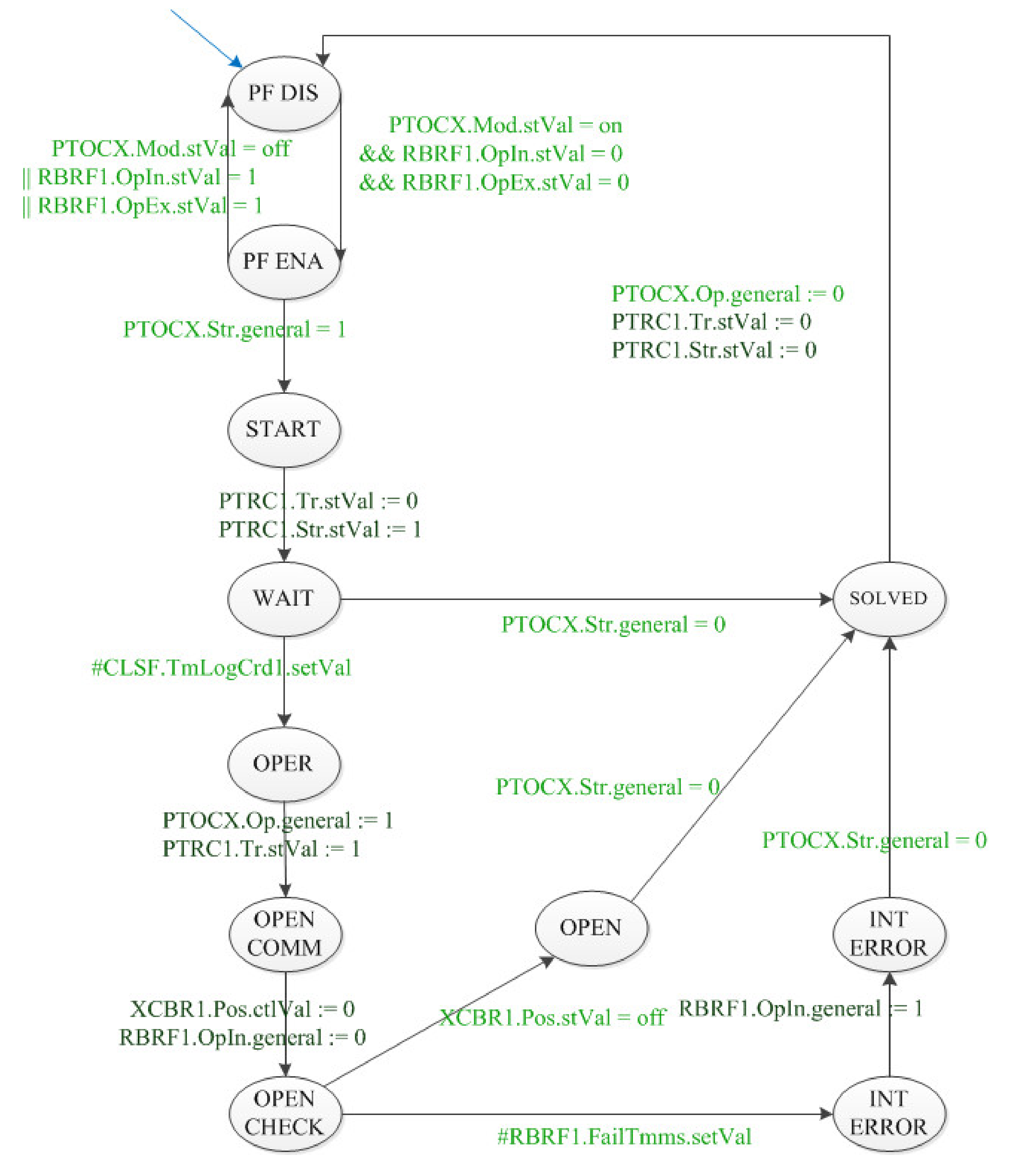
The automaton A3 in Figure 5 is the manager of the logic selectivity associated with a specific PF. This means that automata of type A3 can be instantiated as many times as the number of PFs activated in the IED. The following examples make reference to the PTOC protection functions corresponding to the ANSI PF, like the 67 N and 50/51 P:
- A3 remains in the “PF DIS” state—where the logic selectivity is disabled—until a remote enable is performed by changing the status of the PTOCX.Mod.stVal attribute.
- In the “PF ENA” state, the automaton is waiting for the pickup signal generated by the PF, indicating that a fault has been detected (PTOCX.Str.general = 1).
- Before sending the command to open the breaker, A3 moves to “WAIT0”, checking the following:
- ◦
- If the start signal of the PF went down in the meantime, A3 directly moves to the “SOLVED” state, meaning that the fault was a false-positive.
- ◦
- If the IED receives at least one GOOSE message, this means that another IED is solving the fault, and the automaton enters the “BLOCK”, waiting to move to “SOLVED” as soon as the other IED extinguishes the fault.
- ◦
- If the IED receives no GOOSE messages, A3 continues with the fault management process, moving to “WAIT1/2”, where it remains for a predefined time (PTOCX.OpDITmms.setVal) before starting the sequence to open the breaker. The need for two different waiting states, “WAIT1” and “WAIT2”, is due to the fact that the automaton A3 is valid for the logic selectivity applied both to the 67 and to the 50/51 protection functions.
- A3 raises the operate signal (“OPER” state), and it starts the opening of the breaker, sending to it the opening command (XCBR1.Pos.ctlVal:=1) (“OPEN COMM” state).
- ◦
- If the open command is successful (XCBR1.Pos.stVal = off) then A3 moves to the “OPEN” state and then clears the start signal of the PF, moving to “SOLVED“.
- ◦
- The open command could be not successful, in cases when the circuit breaker is physically stuck (this could happen, e.g., when circuit breakers are old or proper maintenance has not been carried out). This case is recognized because the confirmation of success (XCBR1.Pos.stVal = off) is not received within a fixed time (RBRF1.FailTmms.stVal). In this case, an exception handling state—called “INT ERROR”—is added. A3 remains in this state until another IED operates a breaker to extinguish the fault.
- In the “SOLVED” state, the fault has been solved with the opening of the breaker. The automaton checks that the operating signal is set to zero by the external function which has detected the fault (PTOCX.Op.general = 0). Then, the automaton restarts from the “PF DIS” state, checking if the protection function has been disabled during the execution of the logic.
3.3. 67. N and 50P/51P: Chronometric Selectivity
In the chronometric selectivity (Figure 6), the automata A4 operates in a very similar way as A3. For this reason, only the main branches of the diagram are explained in the following.
In the “WAIT” state, A4 waits for a fixed time (CLSF.TmLogCrd1.setVal).
- If the start signal of the protection function goes down, it means that the logic selectivity was successful, and no further actions are needed (move to “SOLVED”).
- If not, the back-up chronometric selectivity takes care of the fault opening the breaker.
4. Implementation
The present section discusses how the automation system design has been translated into an actual implementation based on a set of interacting IEDs, each of them programmed with local and coordination logics. Furthermore, some examples of a black-box analysis of the automation system report how the system behaves according to the design specification.
4.1. Test Bench
The system setup prepared for the validation phase is based on a real MV network configuration. A primary substation with three MV feeders connected together is depicted in Figure 7a. Each MV feeder, as well as three secondary substations, is fully equipped with circuit breakers with IEDs, being able to detect the fault current regardless of the specific network configuration [8]. For the sake of shortness, in the rest of the paper, it is assumed that the current always flows from the primary substation busbar, along with the three MV feeders. Therefore, light-blue squares indicate IEDs that are active in this specific configuration, where the power flows from the busbar of the primary substation downstream (grey ones are those which are not active). Dashed lines indicate that other secondary substations are present, but these are not shown. Red marks highlight the locations where a fault can occur. To mimic this network, the test bench reported in Figure 7b has been prepared.
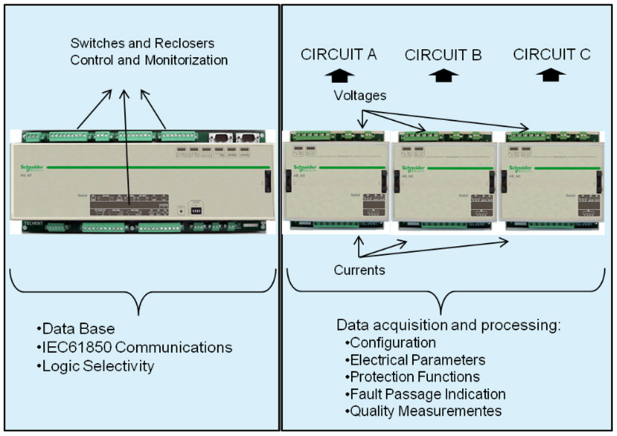
The selected IEDs are from Schneider Electric’s Saitel DR Platform (Figure 8), which provides the following functionalities:
- Configuration of the automata;
- Configurable IEC 61850 GOOSE communications;
- Configurable IEC 61850 MMS server;
- Acquisition and processing of voltage and current AC measurements;
- Fault detection functions.
- The following elements were used and integrated:
- HU_AF: CPU with digital inputs and outputs. The CPU was configured with the IEC 61850 server and GOOSE communications.
- ◦
- Automata were programmed using an IEC 61131-3 programming tool. The selected IEC 61131-3 language was Sequential Function Chart (SFC), which is the most adequate for sequential and parallel control processing.
- ◦
- Digital outputs and inputs were configured as substation circuit breakers, control commands and position status, respectively.
- AB_AC: direct input acquisition block dealing with voltage and current signal acquisition, protection functions and quality measurements in accordance with the configuration set through the IEC 61850 configured IED description (CID) file. One AB_AC module was used for each MV line to be monitored in the substation.
Taking advantage of the Saitel modularity, the test bench was therefore composed of four IEDs:
- IED0—HU_AF_3CB1, composed of three AB_AC acquisition blocks to monitor three MV feeders with three circuit breakers at the primary substation;
- IED1—HU_AF_2CB, composed of two AB_AC acquisition blocks to monitor two MV lines with two circuit breakers at a secondary substation;
- IED2—HU_AF_3CB2, composed of two AB_AC acquisition blocks to monitor three MV lines with three circuit breakers at a secondary substation;
- IED3—HU_AF_3CB3, composed of three AB_AC acquisition blocks to monitor three MV lines with three circuit breakers at a secondary substation.
Power grid behavior was simulated using an OMICROM CMC 353 generator. GOOSE publishing and subscription were set according to the position of the IED in the network and the current flow direction for each validation test. The CMC 535 binary inputs were connected to the RTU output, where operate signals are generated. This configuration is necessary in order to assess the time performance of the system to trip circuit breakers and switches.
4.2. IED Configuration
The automata described above were taken as the reference. The first step for the implementation through the SFC programming language was to identify the inputs and outputs, as well as to classify them by the type of signal. This information was used to create a real-time database embedded in the CPU, in accordance with the required exchange of data with the IEC 61131-3 programming tool.
Then, the SFC automata, linked with the real-time database, were programmed to be run in parallel in the CPU. The priority was assigned to the process dealing with the execution of the SFC routines in a way that it was run immediately after an update of the database. However, this process could be interrupted by a GOOSE message reception, so the blocking signals were processed with no delays upon reception.
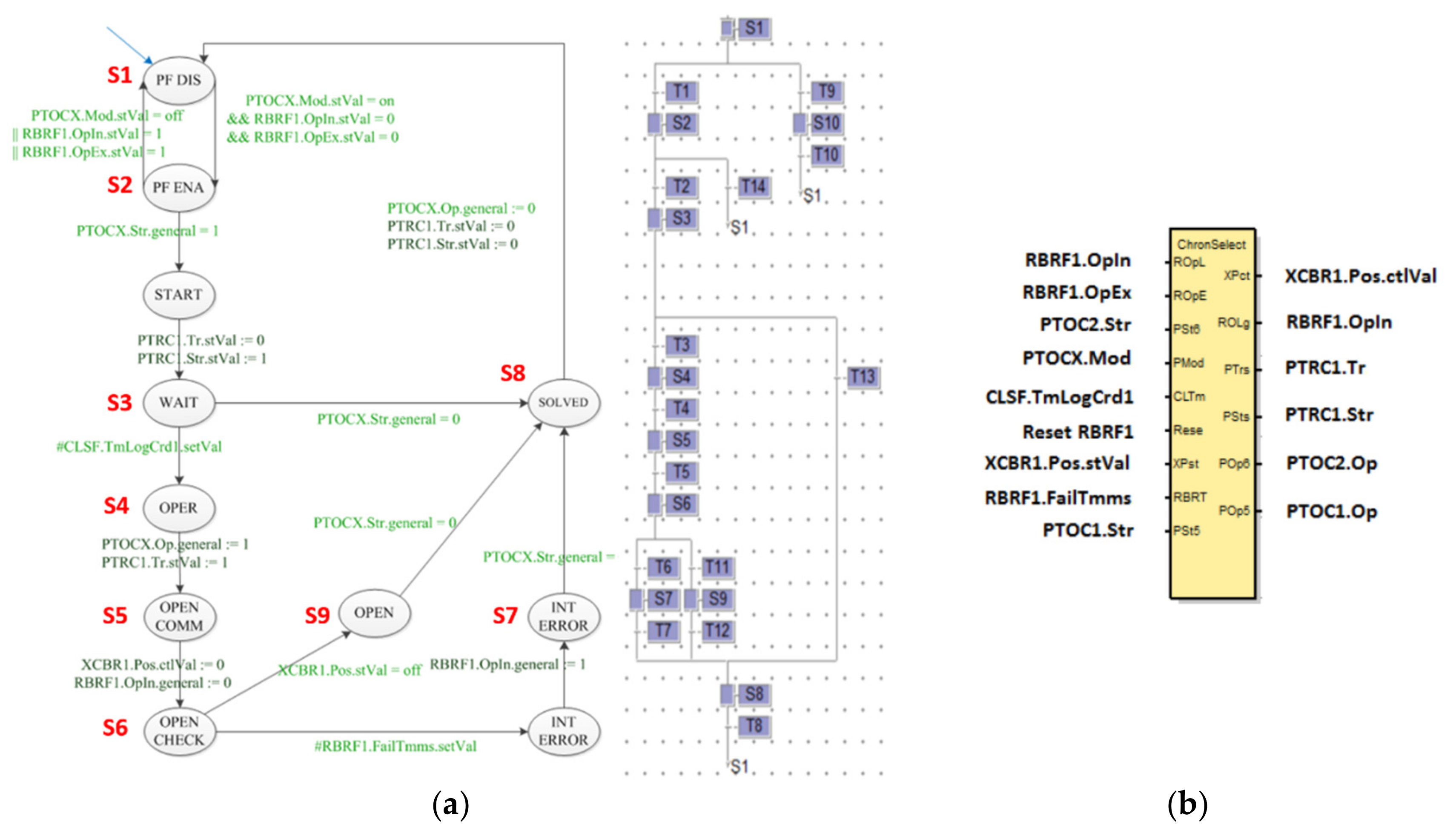
Figure 9a shows the correspondence between the chronometric selectivity automata and the SFC corresponding automata. A library block with input/output assignments has been created for each SFC diagram so that the user can easily create a program with several instances of the same automata, one for each line to be monitored in the substation (Figure 9b).
For each IED, the library blocks for each automata were duplicated for each circuit breaker to be controlled in each position and mapped to the corresponding IEC 61850 inputs and outputs of the real-time database.
5. Validation
A set of test procedures was defined in order to evaluate the functionality and the time performance of the system. In the present section, the paper reports a subset of these tests and comments on some of the most significant results. For example, for the sake of brevity, only results related to the 67 N protection function are included, despite tests on the 67 and the 50 P/51 P having been carried out as well.
The results of the tests were evaluated using the IED Scout tool and RTU console for supervision, a tool provided together with the Saitel Platform. For the suite of tests to be performed in this lab demo test report, the settings reported in Table 4 were selected for each IED.
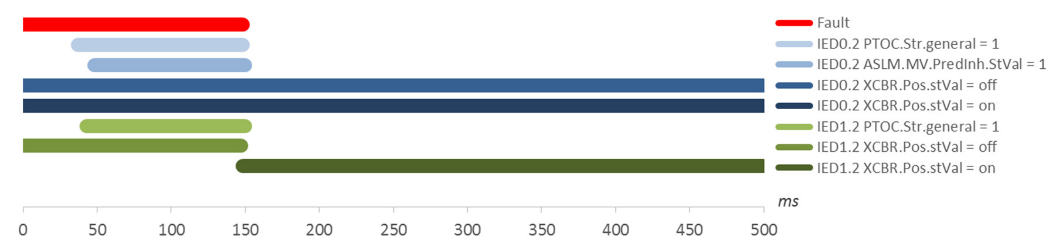
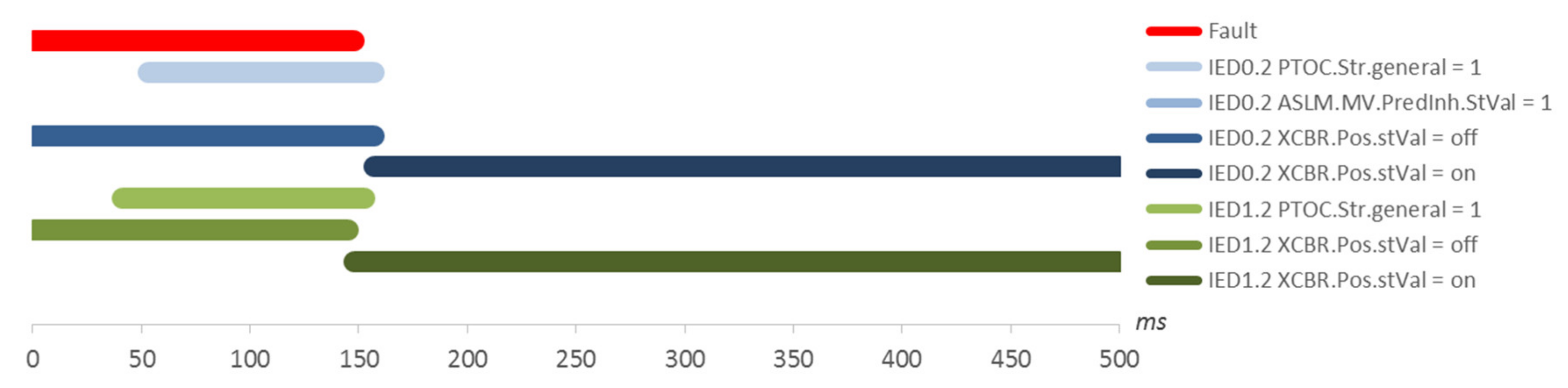
Normal Operation. The initial set of tests that were performed were aimed at evaluating the time performance of the automation system to open the circuit breakers closest to the faults and at the same time to check that no other circuit breakers are tripped in parallel because of failures in the chronometric selectivity. This “normal” operation condition does not consider either issues in the communication network used to drive coordination signals or irregular behaviors of the circuit breaker. These cases are discussed later in the paper. Figure 10 shows the behavior of the system when a fault is simulated on position 4 (see Figure 7a). Similar patterns could be obtained when the fault was injected into the other positions. Some significant signals are highlighted. The fault is detected by the two IEDs at a slightly different time, centered around 40 ms (two wave period). The difference in the detection of the fault is not related to the system configuration. It is rather related to the normal operation of each IED. The automation system is configured to be insensitive to this jitter. While the fault is detected, the two IEDs both raise the PTOC signal related to the 67 N protection function. IED1.2 sends the block signals to IED0.2, which goes to the “block” state. After a period equal to 100 ms (PTOCx.OpDiTmms), IED1.2 trips its breaker and interrupts the fault. IED0.2 sees the anomalous current and moves to the “PF Ena” state.
Figure 11 shows the time performance of the system to operate the circuit breakers in case the faults are in positions 1–4, respectively. Per each fault position, the test has been repeated 50 times. PTOCx.OpDiTmms has been selected as 100 ms and, since the time required by the IED module to determine the overcurrent direction is about 40 ms (two full wave cycles), the expected operation time is around 140 ms. The average value is the same since the operation setting for the logic selectivity is the same in all locations.
As can be noticed, the measures are scattered around this mean value and the range of measurements is not a negligible band. This range is not due to delays or a non-deterministic synchronization among IEDs; it is rather related to the following:
- The variable time to determine the fault. The average time is 40 ms (two periods), but the acquisition unit (AB_AC) of the IED could require a different time depending on the magnitude of the homopolar fault.
- The time to transfer the information from the acquisition module to the head unit of the IED (HU_AF) on the internal bus connecting the two modules and the processes running in parallel into the CPU.
Communication Problems. The following results (Figure 12) report the behavior of the system when coordination signals between IEDs (GOOSE messages) are lost because of a fault/error in the communication network. The starting steps performed by the system are the same as before. However, despite the fact that IED1.2 sends the block signal to IED0.2, this message is not received. As a consequence, both IEDs trip their breakers, opening the feeder in two points (The automation system–as described in this paper–ends his task leaving the MV network opened in two points and delegating to complete the service restoration process to control room operators. To mitigate this condition, another automaton should be added in the main SCADA system to detect this double opening due to communication issues and to automatically close the upstream breaker. However this case is not in scope of the present paper.). Again, we can appreciate from the graph a slight difference in the time of detecting the fault and in the tripping command to the breaker.
Circuit Breaker Operation Fails. The last set of tests is aimed at evaluating the behavior of the automation system when the logic selectivity fails due to a breaker operation failure, thus requiring the chronometric selectivity of the upstream IED to step in. Figure 13 shows the expected behavior in this scenario in accordance with the settings that have been configured. The basic steps of the two IEDs are the same as the previous cases. The block signal by IED1.2 to IED0.2 is sent and received, so IED0.2 goes to the “block” state of the automaton A3, waiting for the fault to be solved by the blocker IED. The chronometric selectivity automaton of IED0.2 (A4) is in the “wait” state. IED1.2 sends the trip to its breaker, but the breaker does not open, so the fault current is not interrupted. After the fixed time CLSF1.TmLogCrd1, IED0.2 determines that chronometric selectivity must solve the issue; therefore, it opens the breaker.
Figure 14 shows the time performance obtained when 50 faults are induced, and the logic selectivity does not operate successfully causing chronometric selectivity to intervene. CLSF1.TmLogCrd1 has been selected to be 190 ms. Adding the usual 40 ms needed by the IED to determine the overcurrent and its direction, the expected operation time of the IED is approximately 230 ms.
6. Discussion and Conclusions
This paper aims at describing a model-based approach to designing complex automation systems composed of the following:
- A local automation process to monitor and protect single nodes of the MV distribution network;
- Peer-to-peer coordination among the protection IEDs located in the primary substation and in secondary substations, designed to be selective with respect to MV faults;
- Hierarchical control to implement classical remote-control schemes from the control center SCADA of a DSO.
Due to the complexity of bringing together the three concepts and letting them coexist, a strong, formal design approach is needed. The result of this design stage is a set of automata describing without ambiguity the behavior of each part of the system, whose interactions are tagged with a set of common signals used for their synchronization.
Labelling those signals with the IEC 61850 naming convention, the design is ready to be implemented in physical devices (IED) to perform lab tests and—at a later stage—to be installed in the field for a real-life application. Taking advantage of modular devices, supporting the IEC 61131 PLC programming, automata can be easily deployed to build a test bench.
To prove this idea, this paper reports a detailed description of an automation system suitable to be used in a real MV network and implementing the following: remote control; management of local/remote behavior; and logic and chronometric selectivity for two protection functions commonly used in European distribution networks.
Within a lab facility, a test bench was implemented to simulate faults in several locations and the behavior of the automation system was assessed. Results related to fault selectivity in normal conditions and in the presence of other issues (namely problems in the communication network connecting the IEDs and the wrong behavior of a circuit breaker) were reported. Based on the data, it is possible to conclude that the overall behavior of the system is compliant with the design.
It is worth underlining that an automation system may include further logics not discussed in this paper. As an example:
- -
- Reclosing logics [7], extremely effective to deal with transitory faults (tree brunches on overhead lines in rural areas, faults caused by MV customers with a wrong setting of their protection interface);
- -
- Fault isolation and service restoration logics—taking advantage of more traditional remote terminal units—may be included as a further improvement to speed up the resupply process of the customers affected by the faults [2];
- -
- Logics to coordinate the DSO’s automation system with distributed generation (DG) in order to avoid the unwanted islanding operation of a part of the grid [22], causing potential safety issues to field crews;
- -
This growing complexity of the overall automation system (omitted in the discussion for the sake of brevity) has the benefit of a strong, formal design approach and of the possibility to easily deploy this design on IEC 61131 programmable IEDs in order to maximize the compliancy between the original specification and the final implementation.
The use of the IEC 61850 data model is another key enabler to provide the straightforward implementation of complex automation logics. In this respect, engineers can benefit from extensions of the data model such as those provided by the IEC 61850-90-6, “Use of IEC 61850 for Distribution Automation Systems”, and the IEC 61850-7-420, “Communications Systems for Distributed Energy Resources (DER)” [25].
Author Contributions
Conceptualization, D.D.G., A.A.d.S. and A.D.; Data curation, A.A.d.S.; Funding acquisition, F.R.; Investigation, A.A.d.S., A.D. and F.R.; Methodology, D.D.G., A.D. and F.R.; Project administration, D.D.G. and F.R.; Resources, A.A.d.S.; Writing—original draft, D.D.G. and A.A.S.; Writing—review & editing, A.D. and F.R. All authors have read and agreed to the published version of the manuscript.
Funding
This research was partially funded by the Seventh Framework Programme European Project IDE4L, under grant agreement no.608860.
Conflicts of Interest
The authors declare no conflict of interest.
References
- Council of European Energy Regulators. CEER Benchmarking Report 5.1 on the Continuity of Electricity Supply, version 11, asblRef: C13-EQS-57-03; Cours Saint-Michel: Brussels, Belgium, 2014. [Google Scholar]
- Chollot, Y.; Wild, J.; Berry, T.; Jourdan, A.; Houssin, J.; Joubert, R.; Raison, B.; Marguet, R. Decentralized self-healing solution tested in the framework of greenlys smart grid project. In Proceedings of the 2013 IEEE Grenoble Conference, Grenoble, France, 16–20 June 2013. [Google Scholar]
- Le, P.; Bui, D.M.; Ngo, C.C.; Le, A.M.T. FLISR Approach for Smart Distribution Networks Using E-Terra Software—A Case Study. Energies 2018, 11, 3333. [Google Scholar] [CrossRef] [Green Version]
- Peretto, L.; Sasdelli, R.; Scala, E.; Tinarelli, R. A distributed measurement system for locating transient-voltage sources. In Proceedings of the 23rd IEEE Instrumentation and Measurement Technology Conference (IMCT 2006), Sorrento, Italy, 24–27 April 2006. [Google Scholar]
- Shahsavari, A.; Fereidunian, A.; Ameli, A.; Mahdi, S.; Lesani, H. A healer reinforcement approach to smart grids by improving fault location function in FLISR. In Proceedings of the 2013 13th International Conference on Environment and Electrical Engineering (EEEIC), Wroclaw, Poland, 1–3 November 2013. [Google Scholar]
- Hadzi-Kostova, B.; Styczynski, Z. Network Protection in Distribution Systems with Dispersed Generation. In Proceedings of the 2005/2006 IEEE/PES Transmission and Distribution Conference and Exhibition, Dallas, TX, USA, 21–24 May 2006. [Google Scholar]
- Della, G.D.; Dedè, A.; Invernizzi, G.; Pozo, D.; Franzoni, F.; Pegoiani, A.; Cremaschini, L. Smart grid automation based on the IEC 61850: An experimental characterization. IEEE Trans. Instrum. Meas. 2015, 64, 2055–2063. [Google Scholar]
- De Sotomayor, A.A.; Della Giustina, D.; Massa, G.; Dedè, A.; Ramos, F.; Barbato, A. IEC 61850-based adaptive protection system for the MV distribution smart grid. Sustain. Energy Grids Netw. 2018, 15, 26–33. [Google Scholar] [CrossRef]
- Della Giustina, D.; Rinaldi, S. Hybrid Communication Network for the Smart Grid: Validation of a Field Test Experience. IEEE Trans. Power Deliv. 2015, 30, 2492–2500. [Google Scholar] [CrossRef]
- Li, W.; Ferdowsi, M.; Stevic, M.; Monti, A.; Ponci, F. Cosimulation for smart grid communications. IEEE Trans. Ind. Inform. 2014, 10, 2374–2384. [Google Scholar] [CrossRef]
- Shah, S.S.; Endsley, E.W.; Lucas, M.R.; Tilbury, D.M. Reconfigurable logic control using modular FSMs: Design, verification, implementation and integrated error handling. In Proceedings of the 2002 American Control Conference, Anchorage, AK, USA, 8–10 May 2002. [Google Scholar]
- Sampath, M.; Sengupta, R.; LaFortune, S.; Sinnamohideen, K.; Teneketzis, D. Diagnosability of discrete-event systems. IEEE Trans. Autom. Control. 1995, 40, 1555–1575. [Google Scholar] [CrossRef] [Green Version]
- Ferrarini, L.; Dedè, A.; Allevi, M. Implementation and testing of an online fault isolation methodology in a real industrial scenario. In Proceedings of the 3rd International Workshop on Dependable Control of Discrete Systems, DCDS 2011, Saarbrucken, Germany, 15–17 June 2011. [Google Scholar]
- Cassandras, C.G.; LaFortune, S. Introduction to Discrete Event Systems; Springer: Boston, MA, USA, 1999. [Google Scholar]
- Andrén, F.P.; Strasser, T.I.; Kastner, W. Engineering smart grids: Applying model-driven development from use case design to deployment. Energies 2017, 10, 374. [Google Scholar] [CrossRef] [Green Version]
- Lewis Blackburn, J. Protective Relaying: Principles and Applications (Electrical Engineering and Electronics); CRC Press: Boca Raton, FL, USA, 1987. [Google Scholar]
- Institute of Electrical and Electronics Engineers. C37.2-2008-IEEE Standard Electrical Power System Device Function Numbers, Acronyms, and Contact Designations; IEEE: Piscataway, NJ, USA, 2008. [Google Scholar]
- International Electrotechnical Commission. IEC Communication Networks and Systems for Power Utility Automation-Part 10: Conformance Testing; IEC 61850-10 ed.; IEC: Geneva, Switzerland, 2012. [Google Scholar]
- Manassero, G.; Pellini, E.L.; Senger, E.C.; Nakagomi, R.M.; Junior, G.M. IEC61850–Based Systems—Functional Testing and Interoperability Issues. IEEE Trans. Ind. Inform. 2013, 9, 1436–1444. [Google Scholar] [CrossRef]
- Wanshui, L.; Dong, L.; Yiming, L.; Pengwei, D.; Fei, P. IEC 61850 Model Expansion Toward Distributed Fault Localization, Isolation, and Supply Restoration. IEEE Trans. Power Deliv. 2014, 29, 977–984. [Google Scholar]
- Silos, Á.; Señís, A.; De Pozuelo, R.M.; Zaballos, A. Using IEC 61850 GOOSE Service for Adaptive ANSI 67/67N Protection in Ring Main Systems with Distributed Energy Resources. Energies 2017, 10, 1685. [Google Scholar] [CrossRef] [Green Version]
- Delfanti, M.; Merlo, M.; Monfredini, G.; Olivieri, V. Coordination of interface protection systems for DG applications in MV distribution networks. In Proceedings of the 22nd International Conference and Exhibition on Electricity Distribution (CIRED 2013), Stockholm, Sweden, 10–13 June 2013. [Google Scholar]
- Delfanti, M.; Komaie, R.; Merlo, M.; Blaco, A.; Bovera, F.; Pozzi, M.; Invernizzi, G.; Vielmini, G.; Moncecchi, M.; Rancilio, G.; et al. Grid-Tie and Off-Grid Operations for an Innovative Microgrid Realized in Leonardo Campus of Politecnico di Milano. In Proceedings of the 2019 IEEE 5th International forum on Research and Technology for Society and Industry (RTSI), Florence, Italy, 9–12 September 2019. [Google Scholar]
- Roman-Barri, M.; Cairo-Molins, I.; Sumper, A.; Sudrià-Andreu, A. Experience on the implementation of a microgrid project in Barcelona. In Proceedings of the 2010 IEEE PES Innovative Smart Grid Technologies Conference Europe (ISGT Europe), Gothenberg, Sweden, 11–13 October 2010. [Google Scholar]
- Ustun, T.S.; Ozansoy, C.; Zayegh, A. Distributed Energy Resources (DER) object modeling with IEC 61850–7–420. In Proceedings of the 2011 21st Australasian Universities Power Engineering Conference (AUPEC), Brisbane, QLD, Australia, 25–28 September 2011. [Google Scholar]
Figure 1.
Simplified scheme of an automation system.

Figure 2.
Relationship between protection functions, coordination logics and data exchange (based on the IEC 61850 standard).
Figure 2.
Relationship between protection functions, coordination logics and data exchange (based on the IEC 61850 standard).

Figure 3.
Automaton A1: digital interface of the circuit breaker—status and command.

Figure 4.
Automaton A2: remote control of the circuit breaker—status and command.

Figure 5.
Automaton A3: 67 N and 50P/51 P—logic selectivity.

Figure 6.
Automaton A4: 67N and 50P/51P—chronometric selectivity.

Figure 7.
Simplified scheme of the medium voltage (MV) network used as reference for the validation phase (a); test bench mimicking the sample MV network (b).
Figure 7.
Simplified scheme of the medium voltage (MV) network used as reference for the validation phase (a); test bench mimicking the sample MV network (b).

Figure 8.
Modular intelligent electronic device (IED) for three-circuit substation.

Figure 9.
SFC implementation for 67 N and 50P/51 P chronometric selectivity (a). IEC61131-3 sequential function chart (SFC) library block and output assignment (b).
Figure 9.
SFC implementation for 67 N and 50P/51 P chronometric selectivity (a). IEC61131-3 sequential function chart (SFC) library block and output assignment (b).

Figure 10.
Some relevant signals of the automation system, indicating its time response when a fault is induced in position 4. The x axis is the time in ms
Figure 10.
Some relevant signals of the automation system, indicating its time response when a fault is induced in position 4. The x axis is the time in ms

Figure 11.
Operation time for logic selectivity in positions 1–4. The y axis is the time in ms. The x axis is the number of repetitions.
Figure 11.
Operation time for logic selectivity in positions 1–4. The y axis is the time in ms. The x axis is the number of repetitions.

Figure 12.
Some relevant signals of the automation system indicating its time response when a fault is emulated in position 4 and with a lack of communication between IED0.2 and IED1.2. The x axis is the time in ms.
Figure 12.
Some relevant signals of the automation system indicating its time response when a fault is emulated in position 4 and with a lack of communication between IED0.2 and IED1.2. The x axis is the time in ms.

Figure 13.
Some relevant signals of the automation system, indicating its time response when a fault is emulated in position 4 and with a failure of circuit breaker operated by IED0.2. The x axis is the time in ms.
Figure 13.
Some relevant signals of the automation system, indicating its time response when a fault is emulated in position 4 and with a failure of circuit breaker operated by IED0.2. The x axis is the time in ms.

Figure 14.
Operation time for the chronometric selectivity in position 3. The y axis is the time in ms. The x axis is the number of repetitions.
Figure 14.
Operation time for the chronometric selectivity in position 3. The y axis is the time in ms. The x axis is the number of repetitions.


Table 1.
Local (L)/remote (R) behavior logic.
| Action On: | L/R Set at a Single IED Level | L/R Set for the Entire Substation |
|---|---|---|
| Physical selector on the IED front Panel | yes | |
| Virtual Selector on the Local SCADA | yes | |
| Virtual Selector on the SCADA |
Table 2.
Conditions to accept a command to change the status of a disconnector/breaker based on the local/remote behavior and who is trying to issue the status change.
Table 2.
Conditions to accept a command to change the status of a disconnector/breaker based on the local/remote behavior and who is trying to issue the status change.
| Command by: | IED Local Status | Substation Local Status | Remote Status |
|---|---|---|---|
| Button on the Breaker | yes | yes | yes |
| Automatic Action by the IED | yes | yes | yes |
| Control Action via the Local SCADA | yes | yes | |
| Control a = Action via the SCADA | yes |
Table 3.
Signals.
| Protection Function | Operation Parameters |
|---|---|
| OPN_DI | analog signal from the open position sensor of the breaker is 24/0 V, meaning the breaker is open/not open |
| CLS_DI | analog signal from the closed position sensor of the breaker is 24/0 V, meaning the breaker is closed/not closed |
| OPN_DO | 24/0 V analog signal sent to open/not open the breaker |
| CLS_DO | 24/0 V analog signal sent to close/not close the breaker |
| XCBR1.Pos.ctlVal | close/open command to the breaker |
| XCBR1.Pos.stlVal | close/open status from the breaker |
| XCBR1.OpCnt.stVal | number of operations of the circuit breaker (to be stored in a non-volatile memory) |
| RBRF1.OpEx.general | the operation of the circuit breaker failed/succeeded after a remote command |
| RBRF1.FailTmms.setVal | timeout to rise the breaking failure notification after a remote command |
| XCBR1.Pos.locKey.stVal | physical selector for local managed breaker status |
| CSWI1.Pos.Loc.stVal | logical selector for local managed breaker status |
| CSWI1.Pos.origin.orCat | station-control => remote command can be performed by the primary substation ONLY remote-control => remote command can be performed by the control center ONLY |
| PTOCX.Mod.stVal | on/off => enable/disable this protection function |
| PTOCX.Str.general | 1/0 => this protection function has detected/has not detected a fault |
| PTOCX.Op.general | 1/0 => this protection function is/is not operating (after a fault) |
| PTOCX.OpDITmms.setVal | trip delay in ms., time to wait before tripping the breaker when a fault is detected |
| CLSF.TmLogCrd1.setVal | chronometric selectivity time in ms |
| PTRC1.Str.stVal | 1/0 => used to synchronize with the reclosing automaton when a protection function peaks up |
| PTRC1.Tr.stVal | 1/0 => used to synchronize with the reclosing automaton when a protection function is ready to trip |
Table 4.
Time settings for validation framework.
| Setting Name | Description | Test Values |
|---|---|---|
| PTOC1.OpDITMMS | Circuit breaker operation 67N | 100 ms |
| CLSF1.TmLogCrd1 | Timer for the coordination of the IED within the chronometric selectivity | 190 ms |
| PTOV2.StrVal | Voltage presence threshold (% reference voltage) | 80 |
| PTUV1.StrVal | Voltage absence threshold (% reference voltage) | 40 |
| PTOV1.StrVal | Residual Voltage Threshold (% reference voltage) | 2 |
| PTOC1.StrVal | Neutral pickup current set stage (A) | 0.25 |
| RDIR1.ChrAng | Neutral maximum torque angle (degrees) | 180 |
| RDIR1.MaxFwdAng | Neutral operating zone (degrees) | 80 |
| PTUV1.OpDITmms | Permanent fault indication set time (ms) | 500 |
| PTOV2.OpDITmms | Voltage presence time for supply recovery (s) | 30 |
© 2020 by the authors. Licensee MDPI, Basel, Switzerland. This article is an open access article distributed under the terms and conditions of the Creative Commons Attribution (CC BY) license (http://creativecommons.org/licenses/by/4.0/).
Share and Cite
MDPI and ACS Style
Della Giustina, D.; Alvarez de Sotomayor, A.; Dedè, A.; Ramos, F. A Model-Based Design of Distributed Automation Systems for the Smart Grid: Implementation and Validation. Energies 2020, 13, 3560. https://doi.org/10.3390/en13143560
AMA Style
Della Giustina D, Alvarez de Sotomayor A, Dedè A, Ramos F. A Model-Based Design of Distributed Automation Systems for the Smart Grid: Implementation and Validation. Energies. 2020; 13(14):3560. https://doi.org/10.3390/en13143560
Chicago/Turabian StyleDella Giustina, Davide, Amelia Alvarez de Sotomayor, Alessio Dedè, and Francisco Ramos. 2020. "A Model-Based Design of Distributed Automation Systems for the Smart Grid: Implementation and Validation" Energies 13, no. 14: 3560. https://doi.org/10.3390/en13143560
Note that from the first issue of 2016, this journal uses article numbers instead of page numbers. See further details here.