Article

Design and Implementation of a Wireless Charging-Based Cardiac Monitoring System Focused on Temperature Reduction and Robust Power Transfer Efficiency

1
The Cho Chun Shik Graduate School for Green Transportation, Korea Advanced Institute of Science and Technology (KAIST), Daejeon 34141, Korea
2
School of Interdisciplinary Bioscience and Bioengineering, Pohang University of Science and Technology (POSTECH), Pohang 37673, Korea
3
Department of Creative IT Engineering, Pohang University of Science and Technology (POSTECH), Pohang 37673, Korea
*
Author to whom correspondence should be addressed.
Energies 2020, 13(4), 1008; https://doi.org/10.3390/en13041008
Submission received: 29 January 2020 / Revised: 18 February 2020 / Accepted: 20 February 2020 / Published: 24 February 2020
(This article belongs to the Special Issue Intelligent Wireless Power Transfer System and Its Application)

Abstract

:
Wireless power transfer systems are increasingly used as a means of charging implantable medical devices. However, the heat or thermal radiation from the wireless power transfer system can be harmful to biological tissue. In this research, we designed and implemented a wireless power transfer system-based implantable medical device with low thermal radiation, achieving 44.5% coil-to-coil efficiency. To suppress thermal radiation from the transmitting coil during charging, we minimized the ESR value of the transmitting coil. To increase power transfer efficiency, a ferrite film was applied on the receiving part. Based on analyses, we fabricated a cardiac monitoring system with dimensions of 17 × 24 × 8 mm3 and implanted it in a rat. We confirmed that the temperature of the wireless charging device increased by only 2 °C during the 70 min charging, which makes it safe enough to use as an implantable medical device charging system.

1. Introduction

Various types of implantable medical devices (IMDs) have recently been developed, including artificial pacemakers, implantable cardiac defibrillators, neuro-stimulators and implantable drug delivery systems [1,2,3,4,5]. These devices use embedded microprocessors to automatically perform health monitoring and therapeutic functions [6,7,8].
The most common method of providing power to operate these IMDs is an internal power source such as an embedded battery. However, batteries must be replaced when they run out, unless they can be recharged. Some IMDs allow the user to replace their IMDs battery by themselves. However, with fully-implanted devices, such as gastric stimulators, pacemakers, and cardiac monitoring systems, the battery requires minor surgery to be replaced. Even though the battery lifetime is roughly 7–15 years, their replacement increases the burden of expense as well as chances of side effects. Moreover, replacing a battery-based IMD via operation introduces the potential for infection as well as creating patient anxiety. IMDs also need to be turned off during the battery replacement, and this can be dangerous.
To eliminate these kinds of problems, wireless power transfer (WPT) systems have been developed for IMDs [9,10,11,12,13]. WPT technology utilizes a magnetic coupling method to transfer power wirelessly and recharge the IMDs. The WPT-based charging system does not require surgery, and the IMDs can continue operating while recharging.
Accordingly, WPT-based IMDs are more convenient and safer, avoiding the potential for infection that comes from minor surgery or exposed electro nodes. With this WPT technology, patients no longer need to worry about their battery running time, since they can charge their implanted device without difficulty.
To employ the WPT system in IMDs, there are two practical issues to consider: miniaturization of the system and thermal radiation. Miniaturization of the IMD is significant in terms of foreign body reaction [14]. Even though a-mm2 sized micro-processor is sufficient for performing health monitoring and analysis, the embedded battery needs to have a specific volume to guarantee the operating time of the implantable devices. Therefore, it is no exaggeration to say that the size of the IMD totally depends on the size of the embedded battery, which is very challenging to miniaturize. To accommodate WPT charging, the IMD must contain a power receiving component, including a power receiving coil, and additional room is therefore necessary. As a result, the receiving coil needs to be designed as small as possible to maximize its usefulness.
Thermal radiation is another parameter to consider. The heat produced by the IMDs’ operation can affect the human body. To guarantee the safety of the WPT IMDs, such thermal radiation should be taken into consideration, especially when power is being transferred [15]. Since a temperature rise of more than 2 °C is not recommended for implanted components, the temperature of the system, especially the components that will be attached on the surface of skin, should be guaranteed to have less than a 2 °C increase [16].
In this study, we designed and implemented a WPT IMD for cardiac monitoring. The dimensions of the fabricated IMD cardiac device including its package are 17 × 24 × 8 mm3, which is comparable to previously studied IMDs [17,18,19,20,21,22,23,24]. In [20,23] the authors fabricated a 10 mm-sized receiving coil, and a 30 mm transmitting coil, achieving power transfer efficiencies of 30% and 7.3%, respectively. Although they reported the system’s power transfer efficiency, thermal radiation, which is significant to the safety of biological tissue, was not discussed. The primary source of thermal radiation comes from joule-loss in the transmitting coil; thus the transmitting coil needs to be designed to have minimum resistance. We also analyzed the topology to achieve robust power transfer efficiency under variable load conditions. Magnetic guidance was employed to maximize power transfer efficiency. As a result, we fabricated a robust, safe, and high-efficiency WPT-based cardiac monitoring module, and demonstrated it in an animal, achieving 44.5% coil-to-coil power transfer efficiency, and obtaining successful electrocardiogram signals.

2. Analysis of Wireless Power Transfer System for the IMDs

A wireless power transfer system is conceptually based on Faraday’s law. When a time-varying magnetic field generated by AC current flows in the transmitting coil, an induced voltage is generated between the ports of the receiving coil. This can be done by magnetic coupling, or mutual inductance between transmitting coil and receiving coil as illustrated in Figure 1. Compensation capacitors are added to achieve maximized power transfer efficiency.

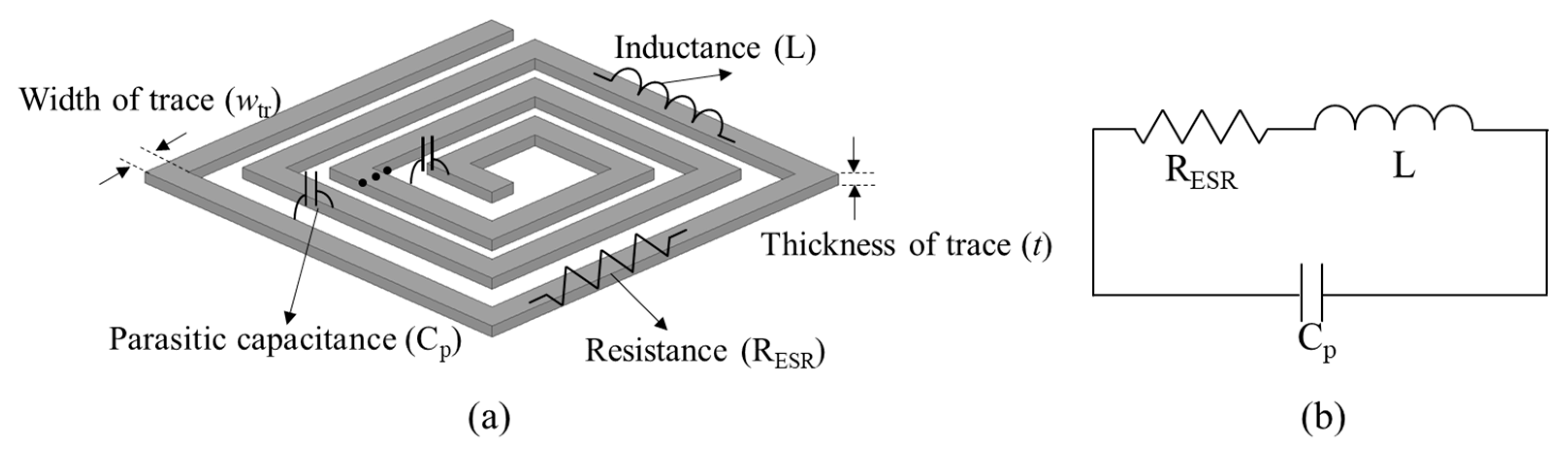
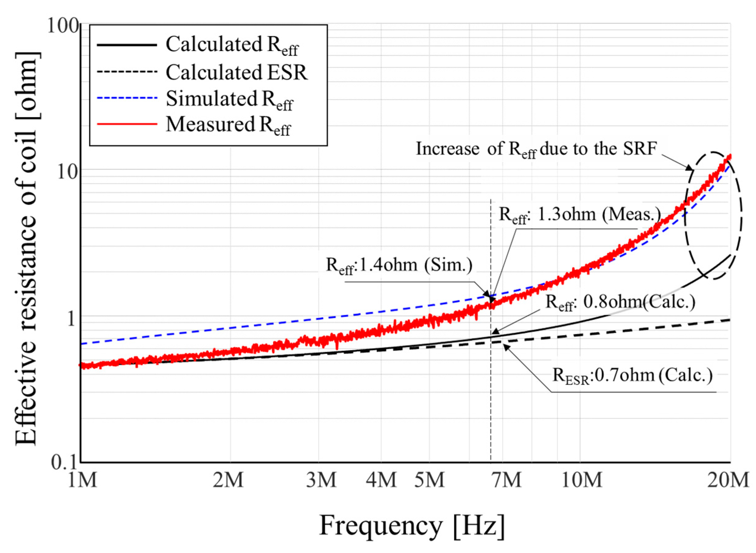
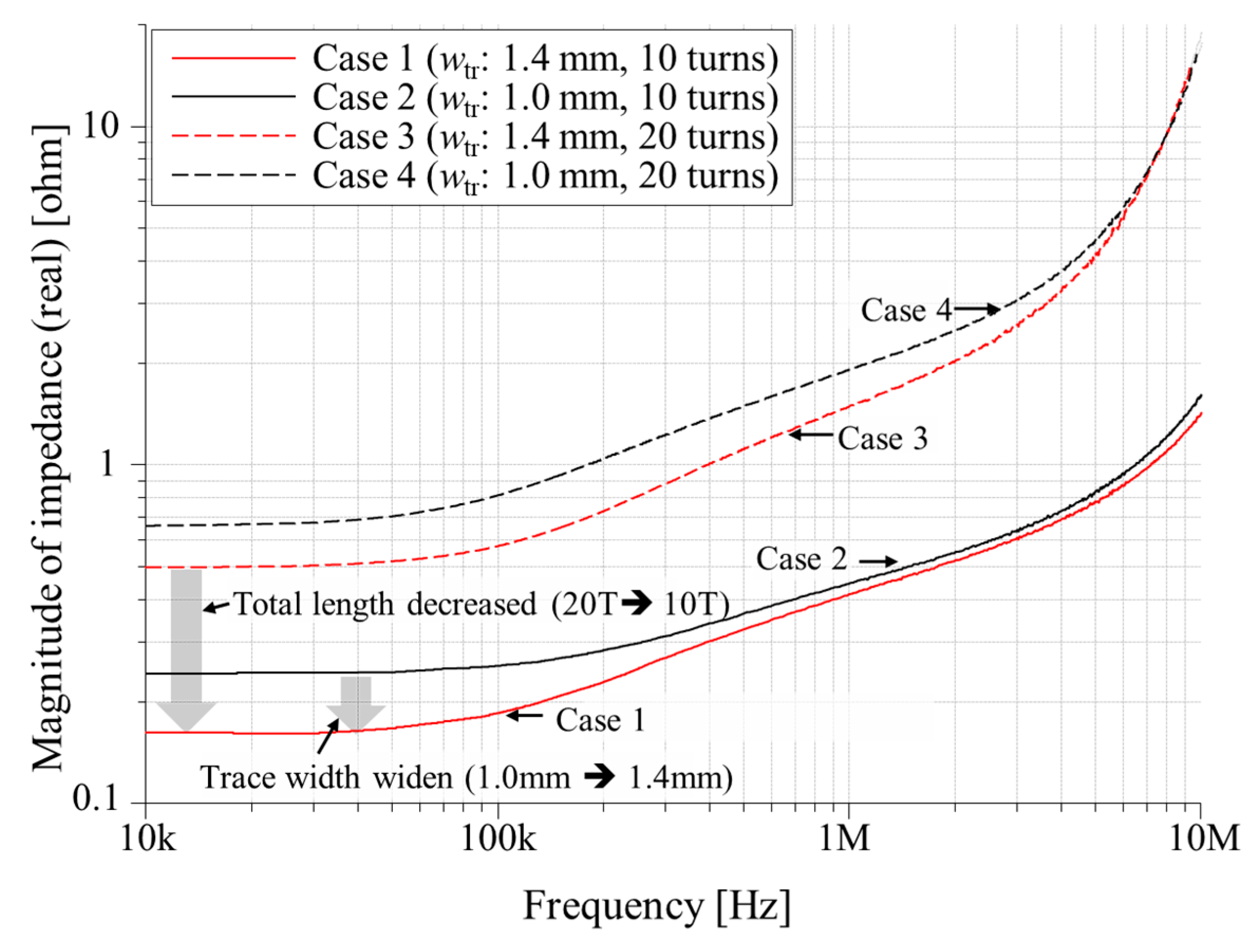
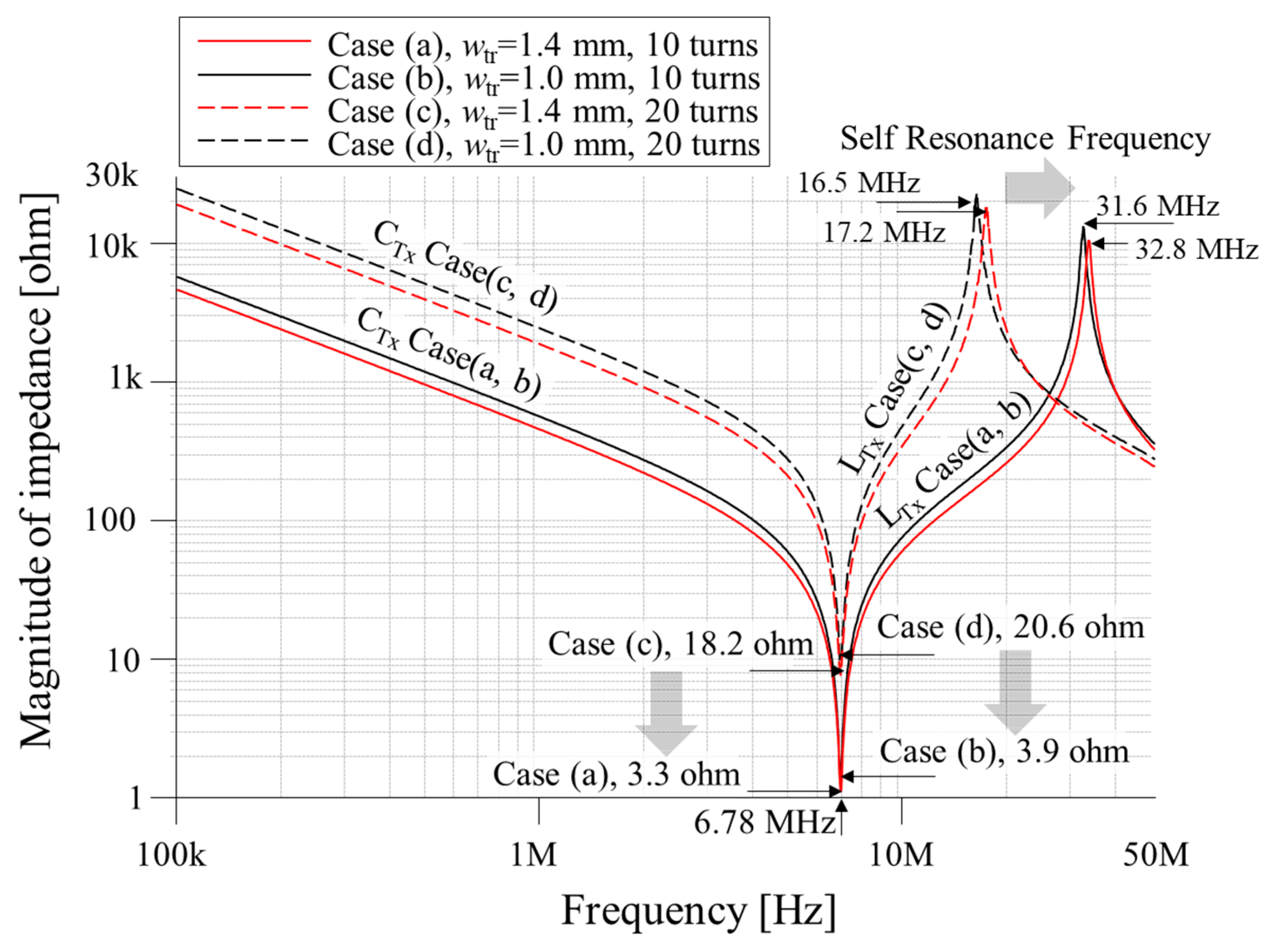
2.1. Design of the Transmitting Coil to Minimize Ohmic Loss

A high frequency coil was designed using a combination of equivalent series resistance (ESR), self-inductance, and the parasitic capacitance of the coil, as depicted in Figure 2a. The ESR is inevitable because the coil is composed of copper, whose conductivity is 5.96 × 10⁷ S/m. The ESR introduces ohmic loss, which is the main source of thermal radiation. For this reason, the WPT system exposes the wearer to thermal energy when power is being transferred. Consequently, the ESR needs to be taken into account when designing WPT coils.
For IMD WPT coils, a printed circuit board (PCB) type coil is most appropriate, considering they can be mass-produced and are robust and consistent. Using the definition of resistance, the ESR of a high-frequency PCB coil can be represented by Equation (1).
R ESR = l t o t a l σ × w t r × t e f f ,
where, RESR, ltotal, σ, wtr, and teff represent the equivalent series resistance, total length of coil trace, the conductivity of copper, effective width of coil trace, and effective thickness of coil trace, respectively. Considering that the effective thickness is related with skin-depth, the effective trace can be described as the following equation.
t e f f = σ s k ( 1 e t σ s k ) ,   where ,   σ s k = 1 σ π μ 0 μ r f ,
where, t and μ 0 , μ r , represent the thickness of the trace, the permeability constant and relative permeability.
For the equivalent circuit of the coil illustrated in Figure 2b, the impedance of the coil can be described with Equation (3). However, the joule-loss or thermal radiation is from the real part of impedance only. Therefore, in this research, we focused on the real part of impedance, the effective resistance (Reff), of the coil. Accordingly, from the parasitic capacitance (Cp) and self-inductance of the coil, we can derive effective resistance at a specific angular frequency ( ω ) using Equation (4). As illustrated in Figure 3, the RESR is the dominant factor when determining the Reff value until the frequency comes close to the self-resonance frequency (SRF). Here, the SRF of coil can be obtained as 1/ 2 π L C p .
Z coil = R ESR + j ( ω L ) ( 1 ω 2 L C p ) + j ( ω R ESR C p )
R eff = R ESR ( 1 ω 2 L C p ) 2 + ( ω R ESR C p ) 2 .
Once the dimension of module is determined, the number of turns and the parasitic capacitance of coil are dimensionally determined and not easy to control. On the other hand, the RESR can be controlled by few parameters as shown in Equation (1). Therefore, minimizing RESR is more reasonable to reduce Reff. Though the multiple number of turns and larger transmitting coil has advantages in that they achieve higher mutual inductance and self-inductance, it also results in greater resistance.
As a result, in this study, we restricted the size of the transmitting coil to be only four-times larger than the receiving coil, and with as many turns as possible. According to Equations (1) and (4), it is obvious that increasing the depth of the trace reduces the effective resistance of the coil. However, considering the effective thickness of the trace, which is introduced by the skin effect, the contribution of depth is minor compared to the trace width. For this reason, we designed the two types of coil whose trace width is 1.4 mm and 1.0 mm. Moreover, to verify the total length of traces 10 turns and 20 turns coils are investigated.
Figure 4 presents the simulated resistances of various transmitting coil designs. Comparing pairs 1, 2 and 3, 4, the effect of trace width can be observed. Cases 2 and 4 have narrower trace widths, and these coils have larger resistance compared to cases 1 and 3. By comparing the pairs, the contribution of total length to impedance can be observed. Because cases 3 and 4 have two-times higher number of turns than cases 1 and 2, they have almost twice the total length. Therefore, they have twice the resistance.

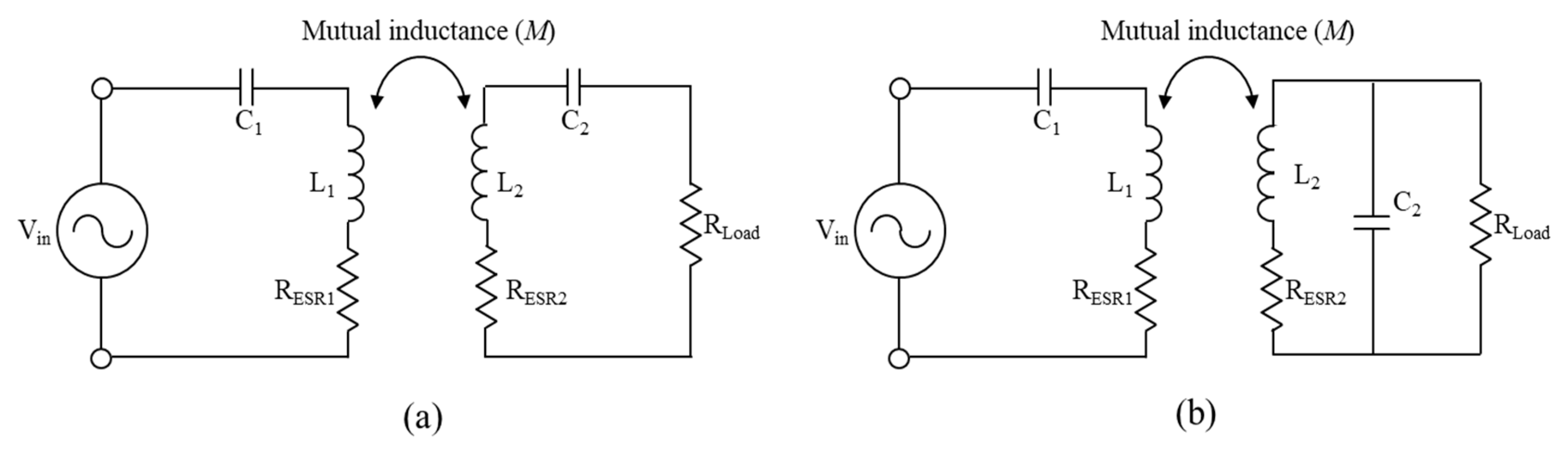
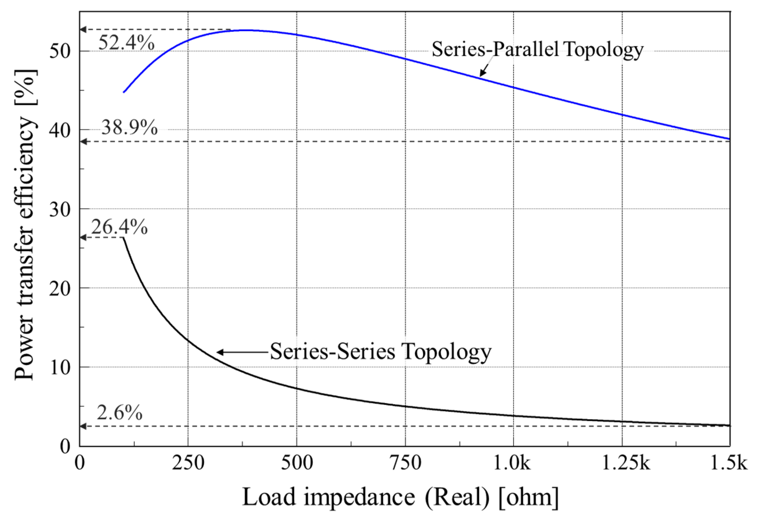
2.2. Topology Analysis for Robust Powering

The WPT system has four main compensating topologies, which are distinguished by their inductance and capacitance connection type; series–series, series–parallel, parallel–series and parallel–parallel [25,26,27,28]. These topologies can be modified or selected depending on their application’s characteristics. In this research, our goal is to induce enough voltage on the receiving module to charge the implanted battery. The induced voltage is proportional to the magnitude of currents and frequency flows in the transmitting coil. For this reason, the LC series connection introduces the maximum current in the transmitting coil since it achieves low impedance at the resonance frequency. Therefore, in this research, we adopted the LC series connection for the transmitting component as illustrated in Figure 5.
For IMDs with an embedded battery, the load impedance condition can change depending on the status of charge (SoC) of the battery. For this reason, the load can vary from ohm to k-ohm. The power transfer efficiency of the series–series topology and series–parallel topology can be derived as shown in Table 1. In addition, based on the parameters listed in Table 1, the power transfer efficiency can be changed as illustrated in Figure 6. While the series–series topology has higher power transfer efficiency in the low load impedance, the series–parallel topology has the advantage in the high load impedance condition. This suggests that the series–parallel topology will be more robust compared to the series–series topology in terms of the battery charging system. For this reason, in this research we used the series–parallel topology to achieve the most robust power transfer efficiency despite the battery SoC.

3. Analysis of Wireless Power Transfer System for the IMDs

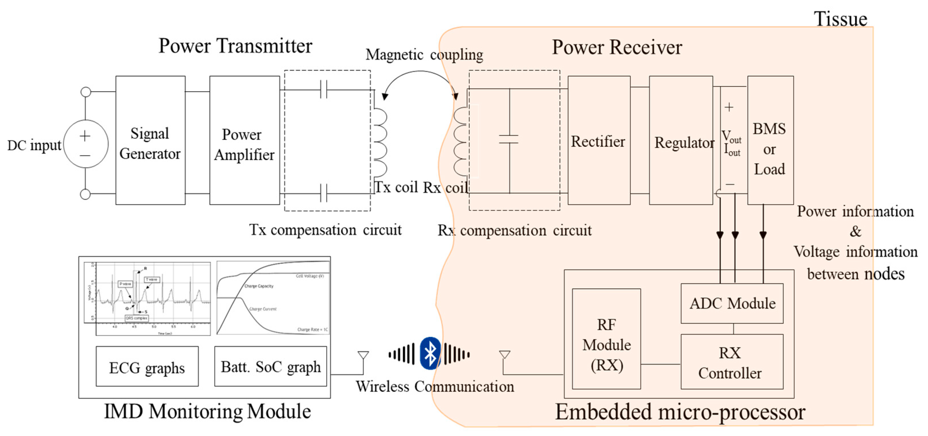
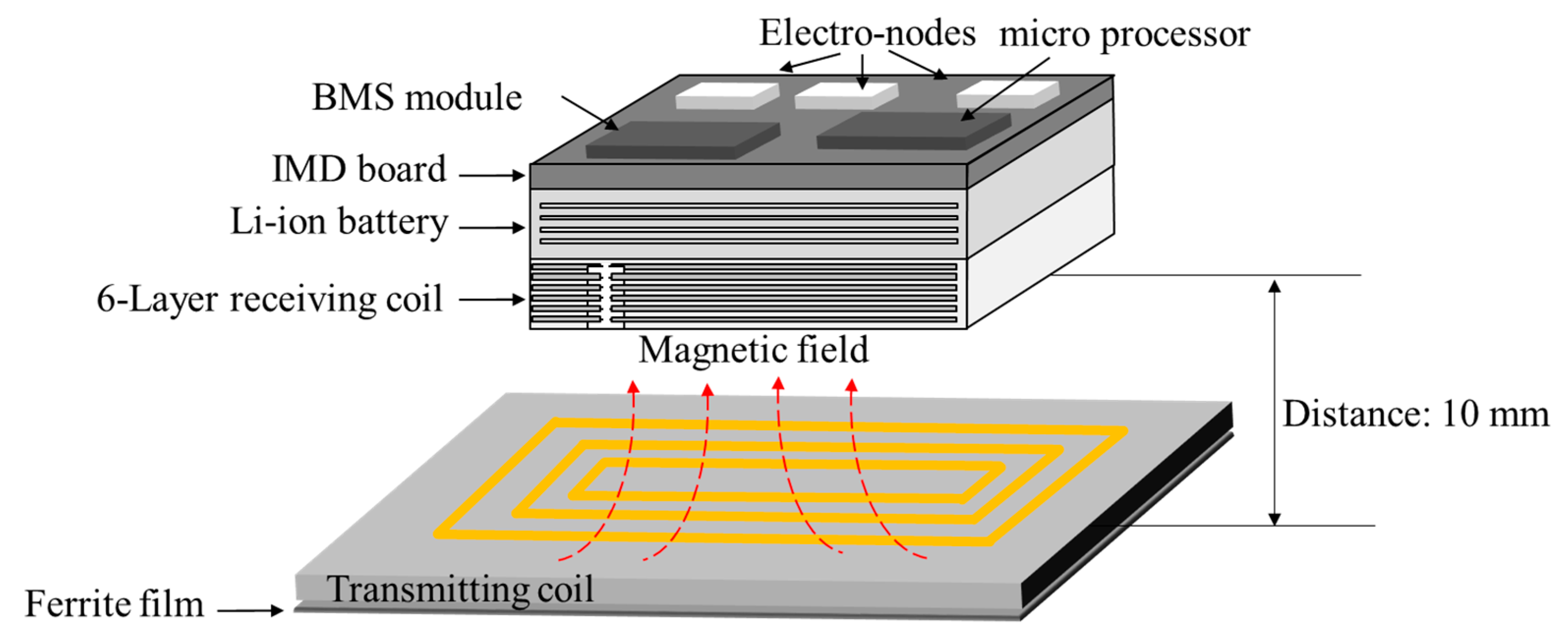
3.1. System Architecture of Cardiac Monitoring System

Figure 7 illustrates a block diagram of the proposed WPT-based IMD module, which is composed of a power transmitter, a power receiver, an embedded micro-processor, a battery management system (BMS), and the external IMD data monitoring component. The embedded micro-processor is continuously powered by the battery, which is charged by the WPT system. The embedded micro-processor collects various information from the IMD module, such as voltage, current level, the SoC of the battery, and captured electrocardiogram (ECG) data. The collected data is continuously sent to the IMD monitoring module, which is transmitted outside biological tissue by wireless communication.
As discussed, the volume of the battery determines the device’s power capacity, and therefore its operating time. In this research, a Lithium-ion battery, FLPB301220, was chosen because its capacity was sufficient to operate the IMD for one day. Because the battery dimension was 15 × 20 × 2 mm3, the receiving coil was smaller than the battery area. To achieve a higher coupling coefficient between the transmitting coil and receiving coil, receiving coil was designed with as many turns as possible, with a 0.5 mm trace width and 0.07 mm thickness. Under the given dimensions, a receiving coil with 6 layers with 6 turns per layer was selected. The battery, and then the IMD board, were located on top of that as illustrated in Figure 8.

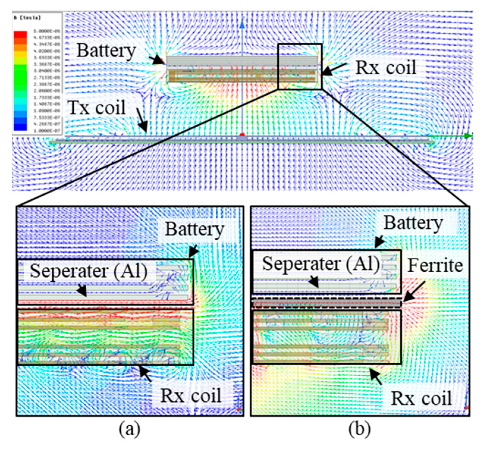
3.2. Magnetic Guidance and Determination of Thickness for Strong Magnetic Coupling

Because the WPT system transfers power through magnetic coupling, a stronger higher mutual inductance allows high power transfer efficiency on both the series–series topology and the series–parallel topology. Even though the magnetic coupling is determined by the size of the coil area, the number of turns of the coil and the distance between the transmitting and the receiving coil, the dimensions were already restricted due to the size limitation. For this reason, it was difficult to increase the magnetic coupling. Moreover, the magnetic flux is disturbed by the battery, because it is composed of multiple metallic separators, as illustrated in Figure 9a. Therefore, in this research, a ferrite sheet was inserted between the receiving coil and battery to guide the magnetic flux, as shown in Figure 9b.
The inserted magnetic material at the bottom of the transmitting coil induces a higher mutual inductance compared to a non-magnetic material. It is obvious that as the volume of the magnetic material becomes larger, the mutual inductance between transmitting coil and receiving coil becomes higher. Nevertheless, in an implantable device it is impractical to increase the volume of the magnetic material indefinitely. Therefore, to find a reasonable volume or depth for the magnetic material, several simulations were conducted. The existence of the magnetic material dramatically influences the mutual inductance. However, the increasing rate of thickness is almost saturated when the thickness of the magnetic material reaches 2 mm. Therefore, considering the relationship between increasing the rate of volume verses the effectiveness of increasing mutual inductances, we concluded that the optimal depth of the transmitting coil was 2 mm.

4. Experimental Verification of Proposed Design

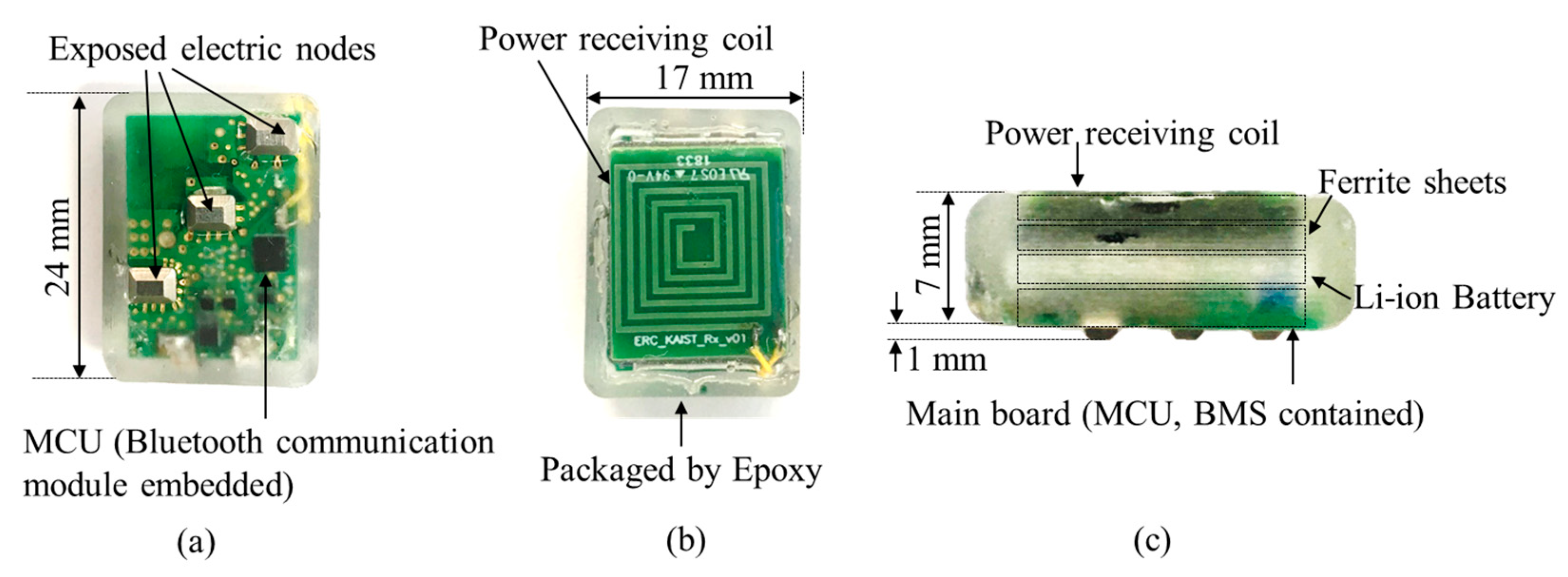
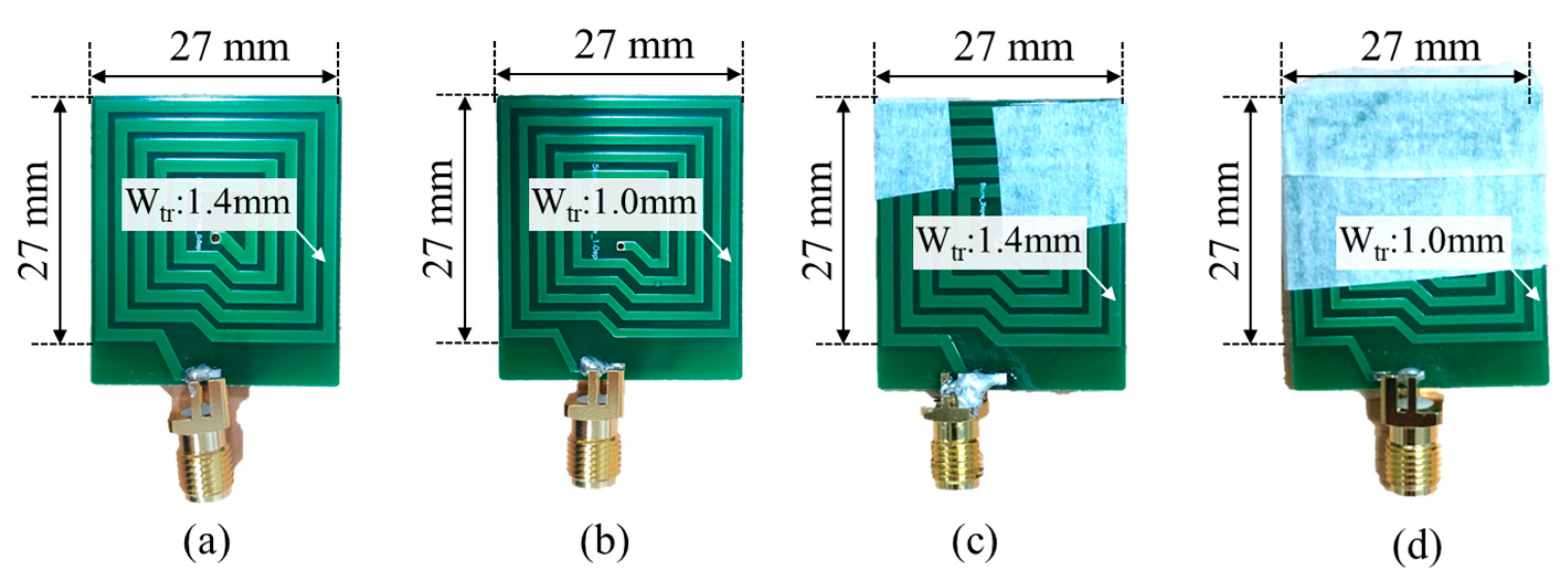
4.1. Fabricated Transmitting Coil and Receiving Coil

To observe the effect of trace width, we designed several transmitting coils with different trace widths. To verify the effect of trace width, we designed the trace width with values of 1.0 mm and 1.4 mm. Then, to observe the effect of total coil length, we designed 5-turn 2-layer coils, and 5-turn 4-layer coils, as illustrated in Figure 10a–d, respectively. The transmitting coils were connected to their own matching capacitors, to make LC series resonance at 6.78 MHz.
We fabricated a 13 mm × 13 mm-sized receiving coil with 6 layers and 6 turns per layer, as described in Figure 11a. The measurement conditions are described in Figure 11b. To reflect the dimensions of the implantable medical device, the Li-ion battery was placed on the receiving coil. A small gap was also introduced between the receiving coil and battery to reduce the magnetic flux disturbance.

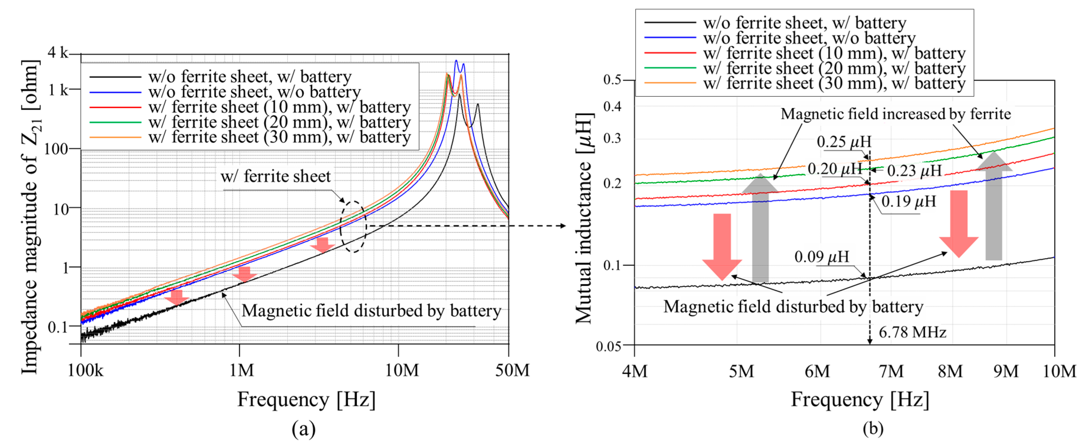
4.2. Measurement Results

The magnitude of impedance of all the coils were measured using a vector network analyzer, an Agilent E5071C. As illustrated in Figure 12, the magnitude of impedance in all cases had a minimum value near 6.78 MHz. The transmitting part was composed of a series matching capacitance, whose value was determined by the operating frequency, 6.78 MHz. By comparing case (a), case (b), case (c) and case (d), it was determined that having wider trace path coils reduced the ohmic loss by around 15%. The lower number of turns achieved around 6 times lower magnitude of impedance in the resonance frequency point. Moreover, the 10 turn coils had a higher SRF, compared to the 20 turn coils, because they had smaller self-inductance.
In order to observe the effect of the magnetic material between the receiving coil and battery, Z21 was measured, as illustrated in Figure 13. Z21 represents the voltage on port 2 (port of receiving coil) over the current in port 1 (port of transmitting coil), so the mutual inductance can be obtained by the imaginary part of Z21 over angular frequency (ω). The black line in Figure 13a represents the Z21 with the battery inserted.
Compared to the blue line, the Z21 and mutual inductances were dramatically decreased when the metallic plate in the battery disturbed the magnetic field. To compensate this phenomenon, the magnetic material was inserted in the vacant area between the receiving coil and battery, as illustrated in Figure 13b. Considering that the relationship between mutual inductance and the thickness of the ferrite sheet on the receiving coil, the thickness of the ferrite sheet was selected to be 2 mm.

5. Animal Experiment

As an application of the WPT IMD, a cardiac monitoring device was fabricated and implanted in a rat, to evaluate the performance of the wireless powered IMD module.

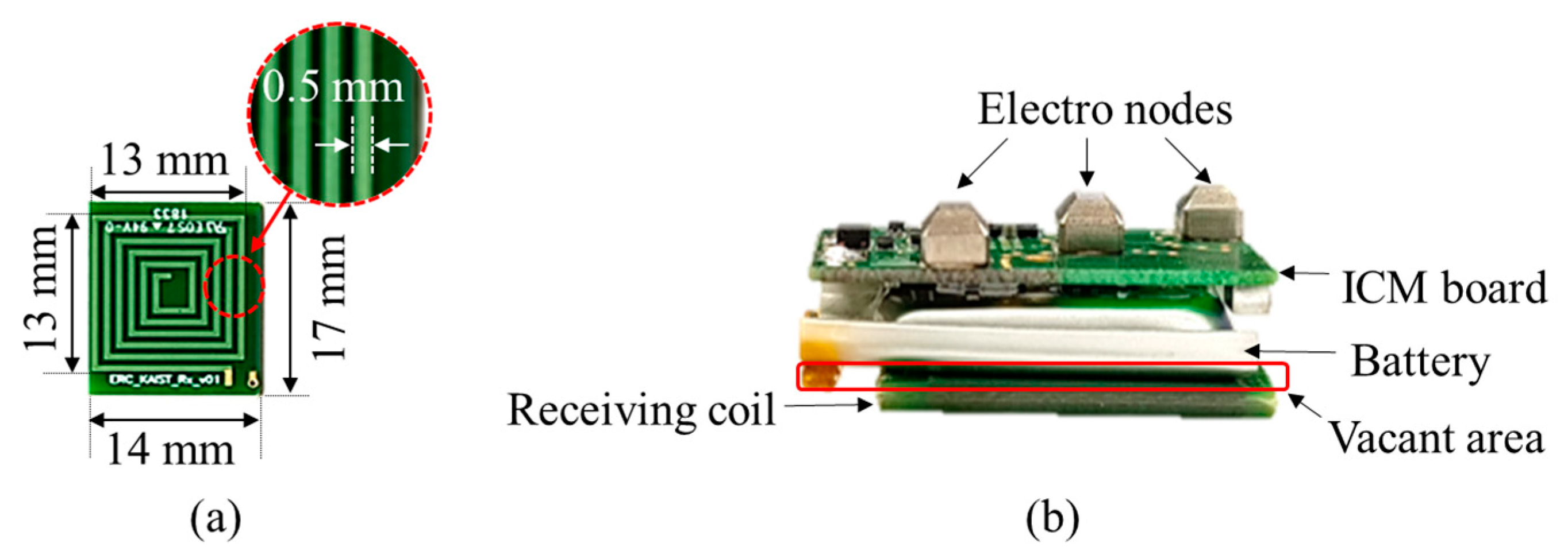
5.1. Fabricated Cardiac Monitoring System Module

The dimensions of the fabricated cardiac monitoring module were 17 × 24 × 8 mm3. As described in Figure 14, the main board contains an MCU (Texas Instruments-CC2640R2F, Dallas, TX, USA) and BMS (Texas Instruments-PQ25100) module. Exposed electric nodes 1 mm in height were attached to the mainboard directly, and connected to the analog digital converter (ADC) channels on the MCU. To monitor the status of the battery, voltage and current sensors were applied and connected to the analog to digital converter (ADC) channel on the MCU. Using a Bluetooth communication module imbedded in the MCU, the collected voltage data from the electric nodes as well as voltage and current level of the battery were continuously transmitted to whoever had Bluetooth communication in the available range.

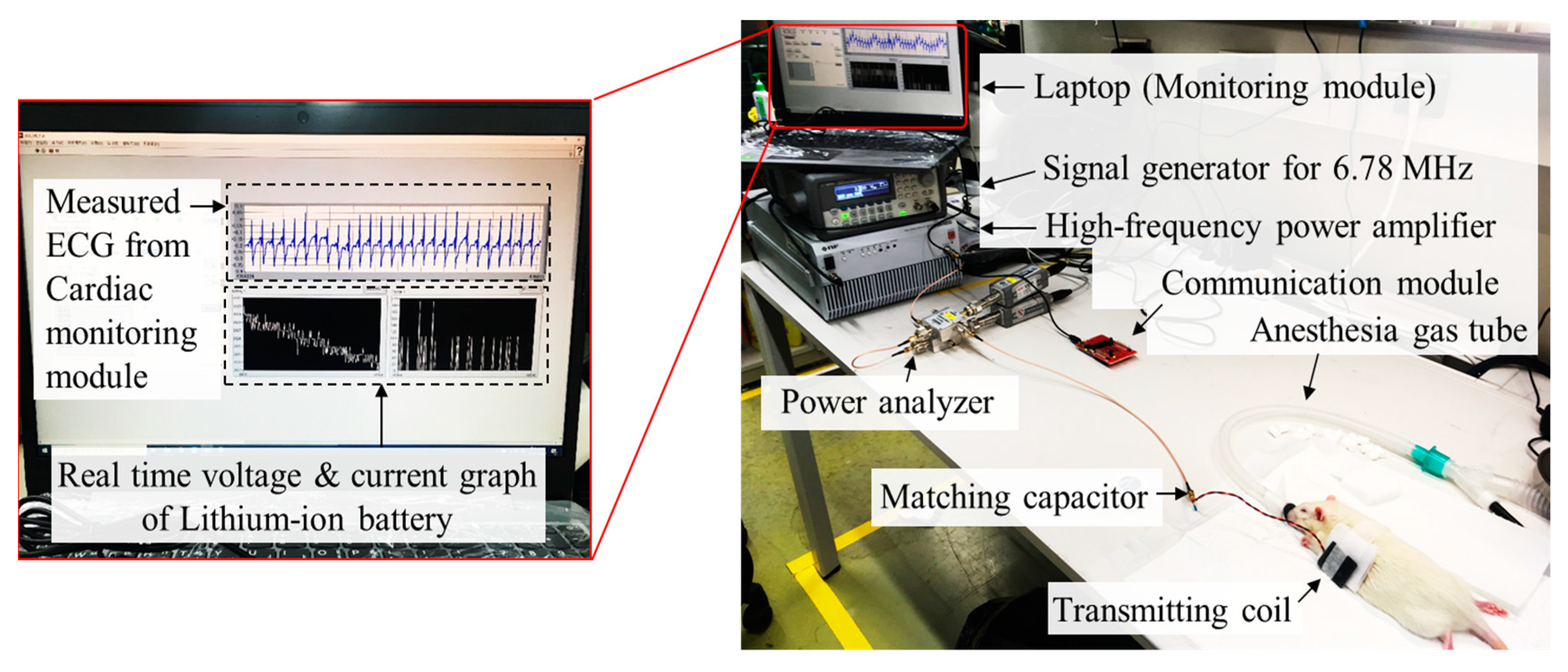
5.2. Animal Experiment Setup

The animal experiment was approved by the Institutional Animal Care and Use Committee (IACUC) at Pohang University of Science and Technology (POSTECH) (approval number: POSTECH-2019-0086). A Sprague Dawley rat (180 g, an 8-weeks old male, ORIENT, Korea) was anesthetized with 2% inhaled isoflurane using gas tube. The cardiac monitoring module was inserted in the dorsolateral site as described in Figure 15.
The experimental setup is described in Figure 16. The anesthesia gas and oxygen were continuously provided through a tube during the experiment, for 100 min, which is enough for experimentation. To guarantee complete wireless charging within 70 min, we checked the current level on the input battery, which was 20 mA at least. A transmitting coil with a 2 mm ferrite sheet on the backside of the coil was attached near the implanted area. The design selected for the transmitting coil was case (a) in Figure 10, which had advantages in terms of resistance at the resonance frequency, and was expected to introduce low thermal radiation.
To reduce the chance of contaminating the surgery area, around 5 mm thick gauze was stacked between the transmitting coil and the rat. For this reason, the distance between the transmitting coil and receiving coil was maintained at 10 mm. Table 2 and Table 3 present the electrical characteristic of fabricated transmitting coils and geometrical characteristics of the power transfer coils used for the experiment. Note that the self-inductance and resistance of the transmitting coil listed in Table 4 is slightly increased, due to the high magnetic permeability of the magnetic material and eddy current loss, compared to case (a) in Table 2.
During the experiment, to minimize the possibility of thermal interference from other electronic devices, the transmitting coil was connected to a 1.0 m SMA cable to guarantee a certain distance. In addition, a matching capacitor, to achieve LC series resonance with the transmitting coil at 6.78 MHz, was attached 10 cm away from the transmitting coil, to prevent heat transfer to the coil from the capacitor.
The power was supplied by a signal generator (Agilent 33220A) connected to a high-frequency power amp (BA4850) to amplify the power level. The output port of the power amplifier was connected in series to a power analyzer to measure the power provided at the transmitting coil. In order to capture the data from the cardiac monitoring module, an evaluation board (Texas Instrument LAUNCHXL-CC2640R2, Dallas, TX, USA) was connected to the laptop. In this way, the data from the cardiac monitoring module could be collected and transferred to a laptop. The captured data was displayed as a voltage, current graph as well as an ECG graph, simultaneously in real time.

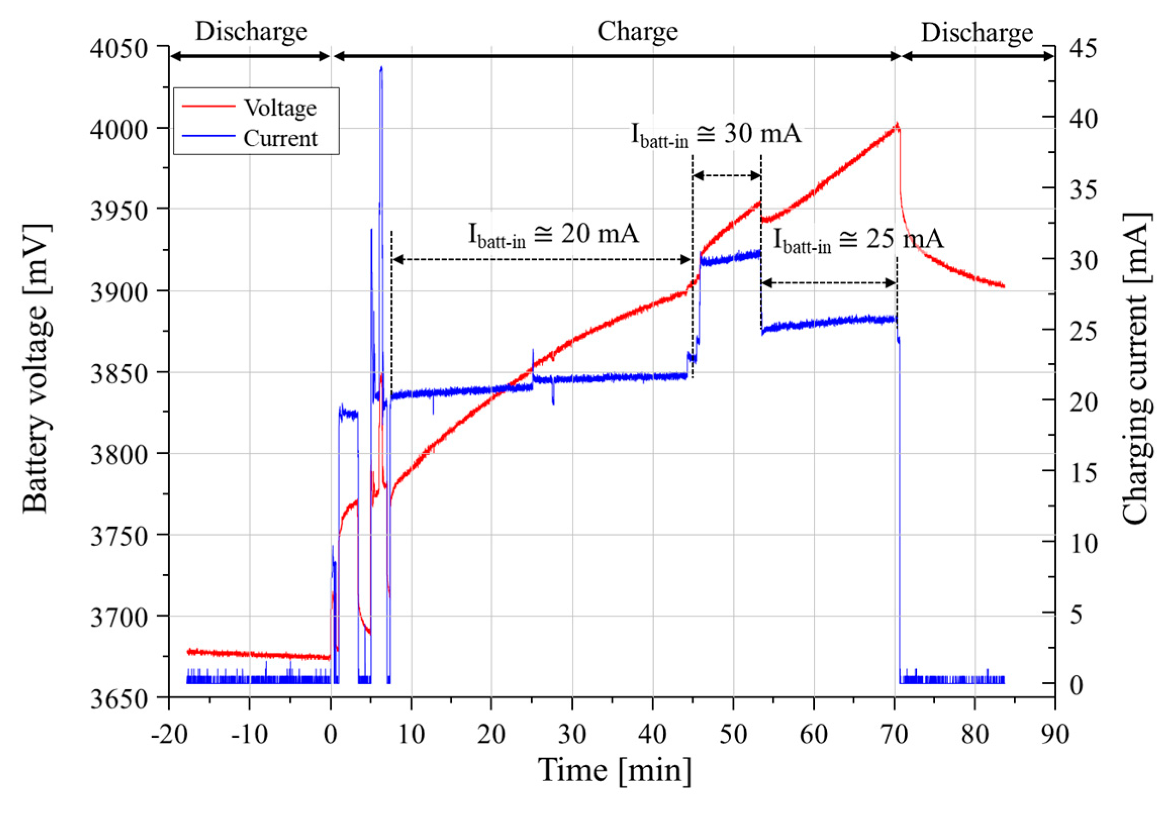
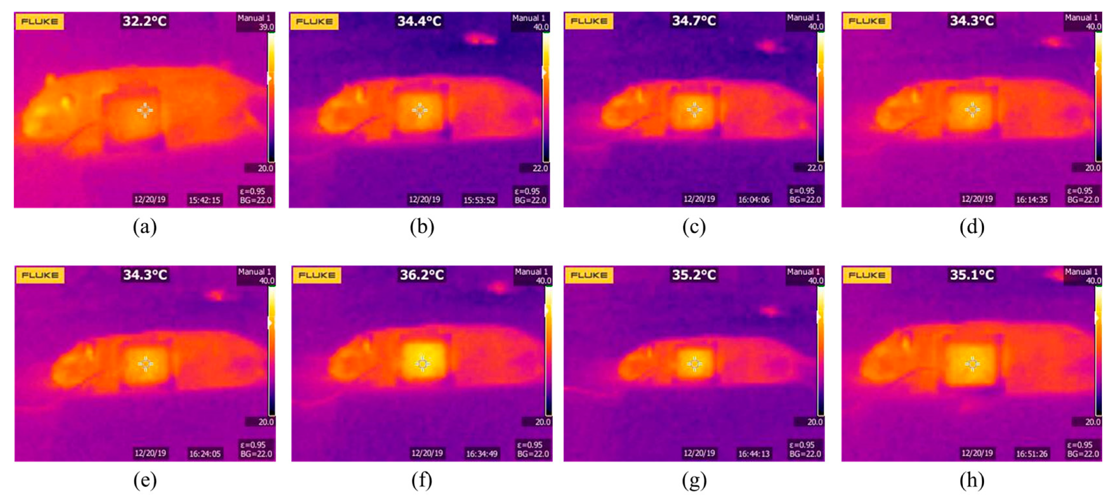
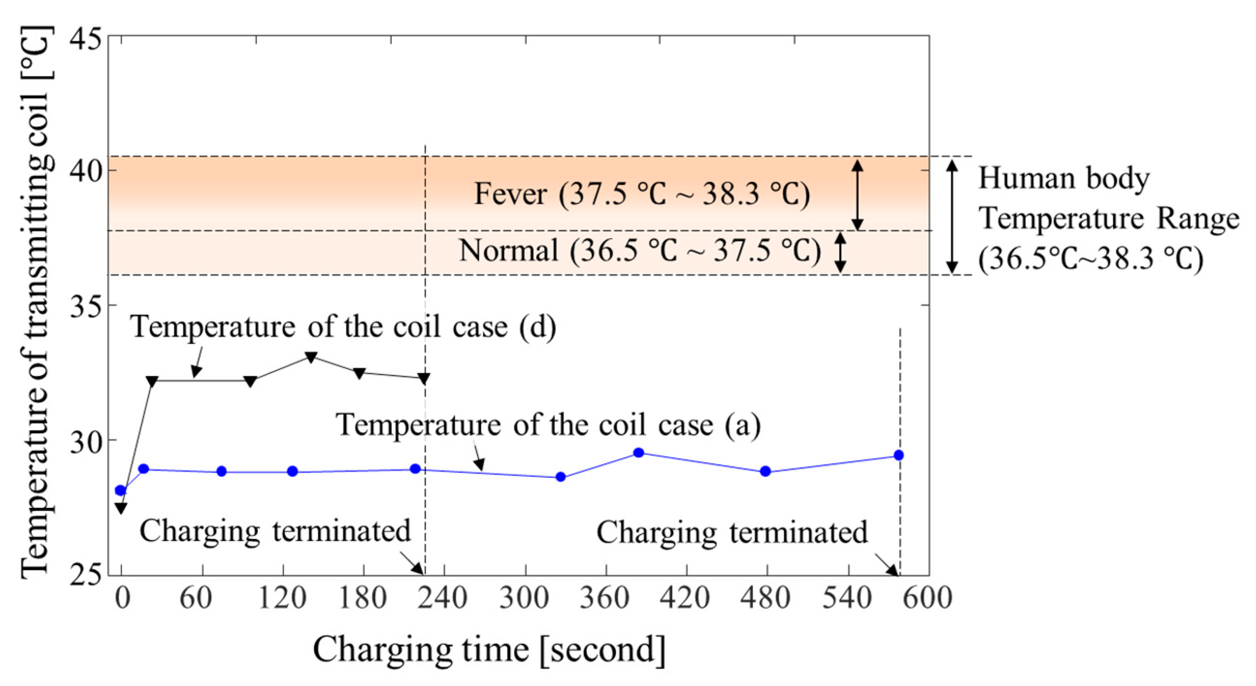
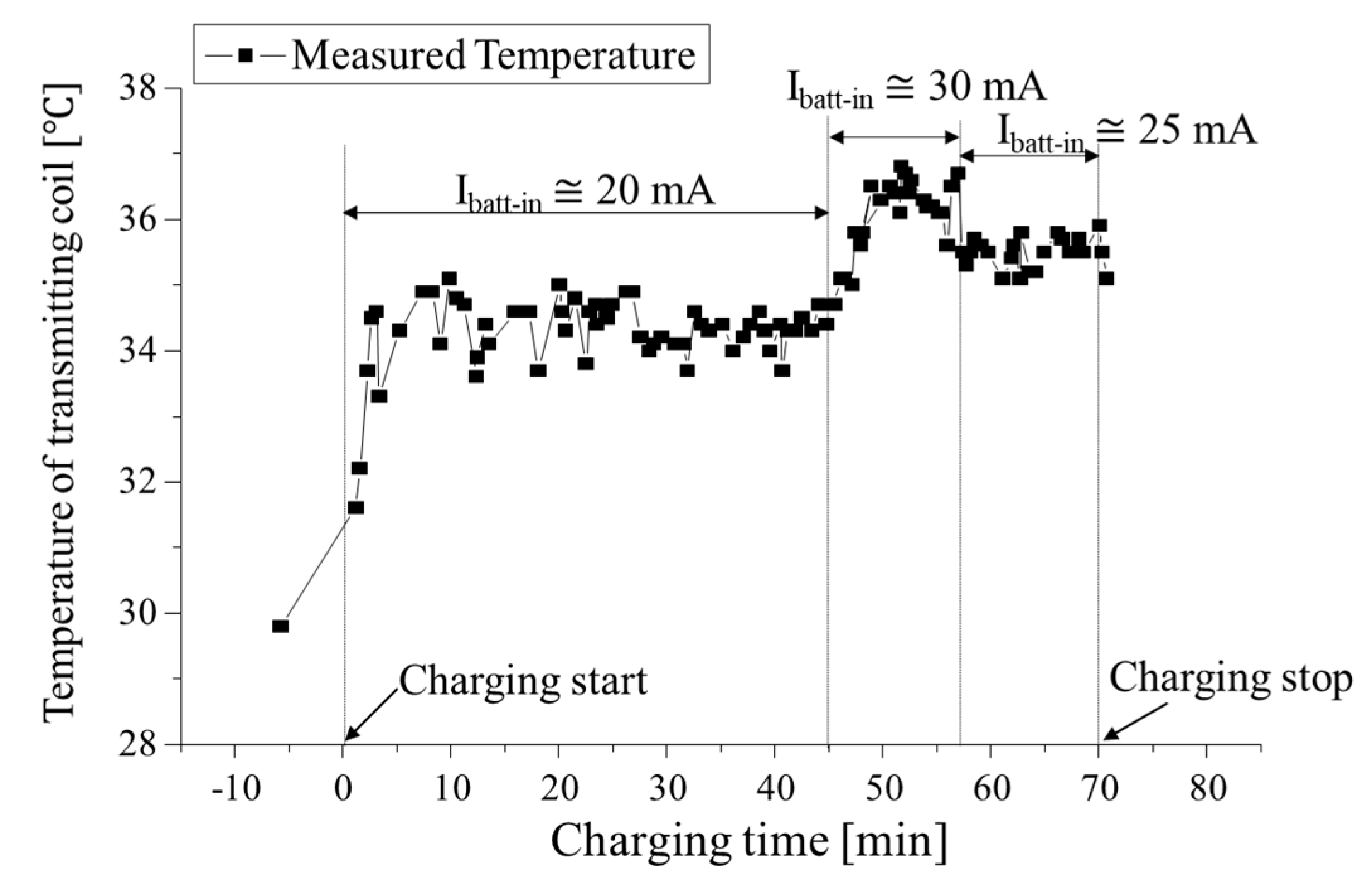
5.3. Experiment Results

Figure 17 illustrates the voltage and current profile of the battery of the cardiac monitoring system. Before the battery was recharged, the battery voltage level continuously decreased. The charging current was set to 20 mA, and when it starts, the current level starts near 20 mA. The battery voltage continuously increased during the charging process as described in Figure 17, shown by the red line. About 45 min after charging began, we set the charging current to 30 mA for about 10 min. During this period, the slope of the voltage profile slightly increased compared with the charging current at 20 mA. After that, we decreased the charging current down to 25 mA for 15 min. Since the impedance of the battery changes depending on its SoC, the input current on the battery slightly changed, while the transmitting power remained constant. Finally, charging stopped when the voltage level of the battery reached 4000 mV, which was 95% SoC of the battery capacity.
In order to measure the temperature of the transmitting coil, a thermal image sensor—FLUKE—S210 was used in this experiment. Figure 18 illustrates the thermal images, which were captured every 10 min. As described in Figure 18f, the transmitting coil temperature increased around 2 °C when the charging current was raised to 20 mA from 30 mA. 10 min later, when the charging current decreased to 25 mA, the measured temperature fell around 1 compared to the 30 mA charging condition.
A temperature graph in Figure 19 presents the measured temperature during battery charging. As can be expected, the temperature of the transmitting coil is highly linked to the battery current profile, since ohmic loss is proportional to the magnitude of current. During charging, the power supplied to the transmitting coil was measured by the power analyzer to be 0.9 W, 1.3 W, and 1.1 W when the charging currents were 20 mA, 30 mA, 25 mA, respectively.
Figure 20 presents the comparison of thermal radiation the transmitting coil case (a) and case (d). This measurement was conducted in the air, and the initial coil temperature was lower than the animal experiment. Nevertheless, the thermal radiation was remarkably decreased case (a) compared to the case (d).
In terms of power transfer efficiency, we recorded the maximum power transfer efficiency as 24% at the battery level is 3.7 V, and the average system efficiency during the full charging was observed as 12.3%, while the coil-to-coil efficiency was measured at 44.5% under a 1333 ohm load resistance. This value is reasonable compare to the previously introduced work in [19,20,21,22,23,24] as listed in Table 5.

6. Discussion

While we successfully powered the cardiac monitoring module 10 mm away from the transmitting coil, there are a few further factors that need to be considered. In this research, we restricted the movement of the animal while the power was being transferred. However, with a more dynamic situation, the effect on heat localization may be more than a 2 °C static measurement. In the experiment in this research, we measured the temperature of the transmitting coil to determine the thermal radiation, since we confirmed that the measured temperature of the transmitting coil surface and the back side (attached region) of the transmitting coil had only 0.1–0.2 °C differences.
Nevertheless, possible temperature issues, including the heat dissipation efficiency of the body and charging under dynamic conditions, could be potential challenges.

7. Conclusions

In this research, we suppressed the thermal radiation of the transmitting coil of the wireless power transfer system. To minimize ohmic losses of the transmitting coil, we widened the trace width, because this is the most effective parameter for reducing the resistance of the coil. In addition, to compensate the reduction in mutual inductance between the transmitting coil and the receiving coil due to the metallic separator inside the battery, a magnetic material was introduced to steer the magnetic path.
To verify the design analysis, various kinds of transmitting coils were fabricated, and their resistance values measured. We also fabricated a cardiac monitoring system as a typical application of an implantable medical device, and successfully recharged it using the wireless power transfer technology. The selected coil model based on our analysis is qualified as a wireless charging module, since it increased in temperature only 2 °C during the 70 min of wireless charging.

Author Contributions

D.K. performed the analysis, experiment, and prepared the manuscript; D.J., J.K. (Jongwook Kim), H.K. and J.K. (Junho Kim) conducted the experiment and analyzed the data; S.-M.P. and S.A. reviewed the paper and contributed the supervision. All authors have read and agreed to the published version of the manuscript.

Funding

This work was supported by the National Research Foundation of Korea (NRF) grant funded by the Korea Government (MSIT) (Grant number: 2017R1A1A1A05001350) and National Research Foundation of Korea (NRF) grant funded by the Korean Government (MSIP) (Grant number: 2017R1A5A1015596).

Acknowledgments

We would like to acknowledge the technical support from ANSYS Korea.

Conflicts of Interest

The authors declare no conflict of interest.

References

  1. Shiba, K.; Morimasa, A.; Hirano, H. Design and development of low-loss transformer for powering small implantable medical devices. IEEE Trans. Biomed. Circuits Syst. 2010, 4, 77–85. [Google Scholar] [CrossRef] [PubMed]
  2. Seo, W.; Kim, N.; Kim, S.; Lee, C.; Park, S.M. Deep ECG-respiration network (DeepER net) for recognizing mental stress. Sensors (Switzerland) 2019, 19, 1–16. [Google Scholar] [CrossRef] [PubMed] [Green Version]
  3. Kim, D.; Kim, M.; Yoo, J.; Park, H.H.; Ahn, S. Magnetic resonant wireless power transfer for propulsion of implantable micro-robot. J. Appl. Phys. 2015, 117, 17E712. [Google Scholar] [CrossRef]
  4. Li, J.; De Ávila, B.E.; Gao, W.; Zhang, L.; Wang, J. Micro/nanorobots for biomedicine: Delivery, surgery, sensing, and detoxification. Science Robotics 2017, 1–10. [Google Scholar] [CrossRef] [PubMed]
  5. Kim, D.; Park, J.; Park, H.H.; Ahn, S. Generation of Magnetic Propulsion Force and Torque for Microrobot Using Wireless Power Transfer Coil. IEEE Trans. Magn. 2015, 51, 2–5. [Google Scholar] [CrossRef]
  6. Xu, S.; Zhang, Y.; Jia, L.; Mathewson, K.E.; Jang, K.I.; Kim, J.; Fu, H.; Huang, X.; Chava, P.; Wang, R.; et al. Soft microfluidic assemblies of sensors, circuits, and radios for the skin. Science 2014, 344, 70–74. [Google Scholar] [CrossRef]
  7. Zheng, G.; Shankaran, R.; Orgun, M.A.; Qiao, L.; Saleem, K. Ideas and Challenges for Securing Wireless Implantable Medical Devices: A Review. IEEE Sens. J. 2017, 17, 562–576. [Google Scholar] [CrossRef]
  8. Bazaka, K.; Jacob, M.V. Implantable devices: Issues and challenges. Electronics 2013, 2, 1–34. [Google Scholar] [CrossRef] [Green Version]
  9. Wu, C.Y.; Qian, X.H.; Cheng, M.S.; Liang, Y.A.; Chen, W.M. A 13.56 MHz 40 mW CMOS high-efficiency inductive link power supply utilizing on-chip delay-compensated voltage doubler rectifier and multiple ldos for implantable medical devices. IEEE J. Solid-State Circuits 2014, 49, 2397–2407. [Google Scholar] [CrossRef]
  10. Hwang, H.; Jo, B.; Kim, S.W.; Moon, J.; Kwon, C. 6.78 MHz resonance coupling for implantable medical devices. BMEiCON 2015-8th Biomed. Eng. Int. Conf. 2016, 2, 1–3. [Google Scholar]
  11. Campi, T.; Cruciani, S.; De Santis, V.; Maradei, F.; Feliziani, M. Near field wireless powering of deep medical implants. Energies 2019, 12, 2720. [Google Scholar] [CrossRef] [Green Version]
  12. Kim, D.; Park, B.; Shin, Y.; Park, H.H.; Ahn, S. Propulsion and Rotation of Microrobot Based on a Force on a Magnetic Material in a Time-Varying Magnetic Field Using a Wireless Power Transfer System. IEEE Trans. Magn. 2020, 56, 1–5. [Google Scholar] [CrossRef]
  13. Campi, T.; Cruciani, S.; Palandrani, F.; De Santis, V.; Hirata, A.; Feliziani, M. Wireless power transfer charging system for AIMDs and pacemakers. IEEE Trans. Microw. Theory Tech. 2016, 64, 633–642. [Google Scholar] [CrossRef]
  14. Pavelec, V.; Rotenberg, B.W.; Maurer, J.T.; Gillis, E.; Verse, T. A novel implantable device for the treatment of obstructive sleep apnea: Clinical safety and feasibility. Nat. Sci. Sleep 2016, 8, 137–144. [Google Scholar] [PubMed] [Green Version]
  15. Tokudaiji, Y.; Miura, D.; Hattori, Y.; Murasato, K.; Bu, Y.; Mizuno, T. AC Resistance Reduction of a Flexible Wireless Power Transmission Coil Using Magnetic Path Control Technology at 13.56 MHz. IEEE Trans. Magn. 2019, 55, 1–7. [Google Scholar] [CrossRef]
  16. Implants for Surgery–Active Implantable Medical Devices–Part 3: Implantable Neurostimulators, 2nd ed.; International Standard, rev.: Geneva, Switzerland, 2017.
  17. Lee, J.H. Human Implantable Arrhythmia Monitoring Sensor with Wireless Power and Data Transmission Technique. Austin J. Biosens. Bioelectron. 2015. [Google Scholar]
  18. Heo, J.C.; Kim, B.; Kim, Y.N.; Kim, D.K.; Lee, J.H. Induction of inflammation in vivo by electrocardiogram sensor operation using wireless power transmission. Sensors 2017, 17, 2905. [Google Scholar] [CrossRef] [Green Version]
  19. Wu, R.; Li, W.; Luo, H.; Sin, J.K.O.; Yue, C.P. Design and characterization of wireless power links for brain-machine interface applications. IEEE Trans. Power Electron. 2014, 29, 5462–5471. [Google Scholar] [CrossRef]
  20. Jow, U.M.; Ghovanloo, M. Modeling and optimization of printed spiral coils in Air, Saline, and Muscle tissue environments. IEEE Trans. Biomed. Circuits Syst. 2009, 3, 339–347. [Google Scholar]
  21. Khripkov, A.; Hong, W.; Pavlov, K. Integrated resonant structure for simultaneous wireless power transfer and data telemetry. IEEE Antennas Wireless Propag. Lett. 2012, 11, 1659–1662. [Google Scholar] [CrossRef]
  22. Xue, R.F.; Cheng, K.W.; Je, M. High-efficiency wireless power transfer for biomedical implants by optimal resonant load transformation. IEEE Trans. Circuits Syst. I Reg. Papers 2013, 60, 867–874. [Google Scholar] [CrossRef]
  23. Monti, G.; Arcuti, P.; Tarricone, L. Resonant inductive link for remote power of pacemakers, IEEE Trans. Microw. Theory Techn. 2015, 63, 3814–3822. [Google Scholar] [CrossRef]
  24. Sun, G.; Muneer, B.; Li, Y.; Zhu, Q. Ultracompact implantable design with integrated wireless power transfer and RF transmission capabilities, IEEE Trans. Biomed. Circuits Syst. 2018, 12, 281–291. [Google Scholar] [CrossRef] [PubMed]
  25. Chopra, S.; Bauer, P. Analysis and design considerations for a contactless power transfer system. INTELEC Int. Telecommun. Energy Conf. 2011, 1–6. [Google Scholar] [CrossRef]
  26. Lu, Y.; Qiu, D.; Meng, X.; Zhang, B.; Tang, S.C. S-PS resonant topology of WPT system for implantable spinal cord stimulator. IET Power Electron. 2018, 11, 2499–2506. [Google Scholar] [CrossRef]
  27. Aditya, K.; Williamson, S.S. Comparative study of series-series and series-parallel topology for long track EV charging application. IEEE Transp. Electrif. Conf. Expo Components, Syst. Power Electron. - From Technol. to Bus. Public Policy ITEC 2014, 2014, 1–5. [Google Scholar]
  28. Gati, E.; Kokosis, S.; Patsourakis, N.; Manias, S. Comparison of series compensation topologies for inductive chargers of biomedical implantable devices. Electronics 2019, 9, 1–21. [Google Scholar] [CrossRef] [Green Version]
Figure 1. Conceptual diagram of the wireless power transfer system. Magnetic coupling enables electrical energy to be transferred wirelessly.
Energies 13 01008 g001
Figure 2. Simplified coil model. (a) The coil is composed of conductive trace which accompanies the resistance and inductance. The parasitic capacitance can be developed between the traces. (b) Equivalent circuit of coil.
Energies 13 01008 g002
Figure 3. Effective resistance of coil. The RESR of coil is determines the effective resistance of coil below the self-resonance frequency.
Energies 13 01008 g003
Figure 4. Simulated results of various coil trace designs. The outermost size of the designed coil was fixed at 27 mm × 27 mm.
Energies 13 01008 g004
Figure 5. Equivalent circuit of the WPT topology showing the series connection on the transmitting part. (a) Series–series topology; (b) series–parallel topology.
Energies 13 01008 g005
Figure 6. Variation in power transfer efficiency depending on changes in load impedance.
Energies 13 01008 g006
Figure 7. Block diagram of the proposed WPT-based IMD cardiac monitoring system.
Energies 13 01008 g007
Figure 8. Assembly of the wireless power transfer-based cardiac monitoring module.
Energies 13 01008 g008
Figure 9. Distribution of magnetic field vectors. The inserted magnetic material detours the incident magnetic flux. (a) Model without magnetic material; (b) model with magnetic material (ferrite).
Energies 13 01008 g009
Figure 10. Transmitting coil fabricated to validate the proposed approach. (a) Fabricated coil with 1.4 mm trace width and 5 turns, 2 layers, (b) fabricated coil with 1.0 mm trace width and 5 turns, 2 layers, (c) fabricated coil with 1.4 mm and 5 turns, 4 layers. (d) Fabricated coil with 1.0 mm and 5 turns, 4 layers.
Energies 13 01008 g010
Figure 11. Fabricated receiving coil and measurement setup. (a) Photograph of fabricated receiving coil. (b) Stacked view to mimic the battery effect.
Energies 13 01008 g011
Figure 12. Measured magnitude of impedance for various coils. The ESR and effective resistance of coils are varied by the trace width and number of turns of coil.
Energies 13 01008 g012
Figure 13. Measured Z21 of the transmitting coil and receiving coil, with various thicknesses of ferrite under the receiving coil. (a) Impedance magnitudes between transmitting coil and receiving coil (Z21) under the various ferrite sheet condition. (b) Calculated mutual inductances @6.78MHz by using Z21 parameters.
Energies 13 01008 g013
Figure 14. Photographs of the fabricated cardiac monitoring system. The outermost size was 17 mm × 24 mm × 8 mm. (a) Bottom view of fabricated ICM module. (b) Top view of ICM module. The ICM module is covered by Epoxy. (c) Side view of ICM module. Ferrite sheets added to enhance the magnetic coupling.
Energies 13 01008 g014
Figure 15. Photographs of the animal experiment. The rat was kept under anesthesia during the experiment. (a) Captured image of the cardiac monitoring system implant surgery. (b) Image of the area of the cardiac monitoring system.
Energies 13 01008 g015
Figure 16. Photographs of animal experiment and ECG, voltage, current of battery graph displayed on monitoring module (laptop).
Energies 13 01008 g016
Figure 17. Measured voltage and current profile of the battery. The charging was conducted at 20 mA for 45 min, 30 mA for another 10 min, and then maintained at 25 mA for the last 15 min.
Energies 13 01008 g017
Figure 18. Temperature measured by thermal image sensor (a) Before charging, and (b)~(h) images captured every 10 min during charging.
Energies 13 01008 g018
Figure 19. Temperature captured by image sensor for 70 min.
Energies 13 01008 g019
Figure 20. Measured temperature of the case (a) transmitting coil and case (d) transmitting coil under air media.
Energies 13 01008 g020
Table 1. Power transfer efficiency of series–series topology and series–parallel topology.
Series–Series (SS)Series–Parallel (SP)
Tx Inductance (L1) 2.68 μ H
Rx Inductance (L2) 1.79 μ H
Mutual inductance 0.21 μ H
Tx matching cap. (C1)
@6.78 MHz
204.9 nF206.8 nF
Rx matching cap. (C2)
@6.78 MHz
307.9 nF307.8 nF
Tx resistance (RESR1)
@6.78 MHz
3.5 ohm4.4 ohm
Tx resistance (RESR2)
@6.78 MHz
3.5 ohm4.4 ohm
Power transfer efficiency 1 1 + R E S R 2 R L + R E S R 1 R L ( R E S R 2 + R L ω 0 M ) 2 1 1 + R E S R 2 R L + R L Q 2 2 R E S R 2 + ( R L Q 2 2 R E S R 2 + 1 ) 2 R E S R 1 L L 2 M 2 R L , where Q 2 = ω L 2 R E S R 2
Table 2. Measured electric characteristic of fabricated transmitting coil.
ParameterCase (a)Case (b)Case (c)Case (d)
Number of turns10102020
Resistance [ohm] (@ 6.78 MHz)3.33.918.220.6
Self-inductance [ μ H] @ 6.78 MHz1.62.06.68.6
Matching capacitance [pF] @ 6.78 MHz344276 8364
Self-resonance frequency (SRF) [MHz]32.831.616.517.2
Table 3. Geometrical characteristic of wireless power transfer system coils for experiment.
ParameterTransmitting CoilReceiving Coil
Number of turns1036
Coil size27 × 27 × 0.5 mm317 × 19 × 1 mm3
(coil area: 13 × 13 mm2)
Thickness of coil trace0.035 mm (1 oz)0.07 mm (2 oz)
Width of coil1.4 mm0.5 mm
Air gap10 mm
Table 4. Electrical characteristic of wireless power transfer system coils for experiment.
ParameterTransmitting CoilReceiving Coil
Coil resistance (ReffTx, ReffRx)3.52 ohm4.37 ohm
Self-inductance (L1, L2) 2.68 μ H 1.78 μ H
Mutual inductance (M)234.19 nH
Resonance matching capacitor (C1, C2) @ 6.78 MHz205 pF310 pF
Table 5. Comparison of the proposed design with related works.
Ref.[19][20][21][22][23][24]This Work
Operating frequency [MHz]7.413.566.7813.5640339.866.78
Dimensions of the receiver [mm2]4.5 × 4.5 10   × 10 12   × 12 25   × 10 9.5   × 9.5 10.9   × 10.5 13   × 13
Coil to coil distances [mm]51020 (air)10101010
Power transfer efficiency33.1%30%38%* 58.2%7.3%47.224% (* 44.5%)
* Coil to coil efficiency.

