
Various Trade-Off Scenarios in Thermo-Hydrodynamic Performance of Metal Foams Due to Variations in Their Thickness and Structural Conditions


1
Department of Mechanical Engineering, National Institute of Technology Karnataka, Surathkal, Mangalore 575025, India
2
Mechanical Engineering Department, Faculty of Engineering, Shizuoka University, 3-5-1 Johoku, Naka-ku, Hamamatsu-shi 432-8561, Japan
*
Authors to whom correspondence should be addressed.
Energies 2021, 14(24), 8343; https://doi.org/10.3390/en14248343
Submission received: 26 October 2021
/
Revised: 1 December 2021
/
Accepted: 6 December 2021
/
Published: 10 December 2021
(This article belongs to the Special Issue Advances of Heat Transfer in Porous Media)
Abstract
:The long standing issue of increased heat transfer, always accompanied by increased pressure drop using metal foams, is addressed in the present work. Heat transfer and pressure drop, both of various magnitudes, can be observed in respect to various flow and heat transfer influencing aspects of considered metal foams. In this regard, for the first time, orderly varying pore density (characterized by visible pores per inch, i.e., PPI) and porosity (characterized by ratio of void volume to total volume) along with varied thickness are considered to comprehensively analyze variation in the trade-off scenario between flow resistance minimization and heat transfer augmentation behavior of metal foams with the help of numerical simulations and TOPSIS (Technique for Order of Preference by Similarity to Ideal Solution) which is a multi-criteria decision-making tool to address the considered multi-objective problem. A numerical domain of vertical channel is modelled with zone of metal foam porous media at the channel center by invoking LTNE and Darcy–Forchheimer models. Metal foams of four thickness ratios are considered (1, 0.75, 0.5 and 0.25), along with varied pore density (5, 10, 15, 20 and 25 PPI), each at various porosity conditions of 0.8, 0.85, 0.9 and 0.95 porosity. Numerically obtained pressure and temperature field data are critically analyzed for various trade-off scenarios exhibited under the abovementioned variable conditions. A type of metal foam based on its morphological (pore density and porosity) and configurational (thickness) aspects, which can participate in a desired trade-off scenario between flow resistance and heat transfer, is illustrated.
Keywords:
metal foams; thickness ratio; pore density; porosity; heat transfer; pressure drop; trade-off; TOPSIS1. Introduction
Metal foams have been widely researched for their excellent thermal transfer augmenting potential due to their extraordinary heat conducting properties, high surface area density and other desired properties such as high strength and low density. Applications where metal foams have been found to be advantageous include hotspot removal in electronic equipment [1,2] thermal energy storage [3,4], photo voltaic panel [5], thermal management in batteries [6,7], boiling heat transfer [8], solar collectors [9,10], etc. However, the benefit of augmented heat transfer with the use of metal foams in heat exchanging applications is always compromised by increased pressure drop due to high flow obstruction offered by such materials. Hence, it is crucial to analyze the thermo-hydraulic behavior of metal foams with both flow resistance and heat transfer enhancement. Several factors that influence flow and heat transfer through metal foam include material aspects (thermal conductivity [11]), structural aspects (porosity and pore density [12]), configurational aspects (thickness [11,13] and partial filling [14,15]), the foam geometrical aspect (shape [16]), and the arrangement aspect (foam multi-layer [17]), etc. It is interesting to note that different combinations of these aspects result in varied pressure drop and heat transfer, thus allowing a better trade-off between enhanced heat transfer with the accompanied increased pressure drop. In this regard, heat transfer and flow influencing, structural (pore density and porosity) and configurational (thickness) aspects that can be altered resulting in varied magnitudes of both heat transfer as well as flow characteristics of a thermal system involving metal foam are analyzed in this study.
In the previous studies [12,18], the influence of structural aspects (PPI and porosity) on varied flow resistance and thermal transmission behaviors was illustrated, highlighting the optimum selection of foam samples based on their structural aspects for a desired thermo-hydraulic performance. However, it is interesting to analyze the thermo-hydraulic performance of metal foams subjected to further accompanied variable conditions such as varied thickness scenarios. Many works involving investigation of optimum performance of high flow resistance inducing metal foams include either partial filling scenarios (varying thickness) or varying structural aspects (pore density and porosity). As per our best knowledge, there is no work in the literature that reflects the combined effect of varying thickness along with variations in structural aspects to describe varied magnitudes of flow resistance and thermal transmission in a system with metal foams.
Zuo et al. [19] numerically investigated optimal design of partially filled metal foams on the improved performance of a latent thermal storage component. Various filling thicknesses and filling angles were considered. Sardari et al. [20] performed a numerical study to investigate the behavior of a heat storage system with copper foam and phase change material. They considered foam structural variables such as porosity and pore density with different heater locations. Higher rates of heat transfer were observed with the addition of metal foam. The effect of porosity and PPI on temperature and liquid fraction in the porous-PCM heat storage unit was illustrated in this study. The significance of metal foams in enhancing heat transfer in heat storage units can also be seen in a study by Mohammed et al. [21]. The authors took the effect of pore density into consideration and observed that using metal foams of higher PPI, the circulation of generated heat in the domain gets more uniform, aiding the melting process. Recent studies also focused on numerical modeling of porous media with high Prandtl number fluids to analyze various naturally occurring phenomena [22]. Li et al. [23] experimentally investigated the enhancement of heat transfer using a partially filled gas tube with metal foams. The study revealed that for a considered thickness and porosity condition, an increase in PPI increased the heat transfer. Bianco et al. [24] made an attempt to understand the trade-off between pressure drop and heat transfer in a heat sink with metal foam and metal foam fins. They provided optimization procedures to enhance heat transfer at a given pumping power with the help of Pareto plots. Siavashi et al. [25] considered gradient and multilayered metal foams to understand flow and heat transfer behavior with nanofluid as the working fluid. Optimized properties of metal foams and various types of arrangements to enhance heat transfer with reduced pumping power were analyzed. Anuar et al. [26] investigated the effects of pore density and height of metal foam on pressure drop characteristics. The study reported an enhancement of pressure drop with an increase in blockage ratio and pore density. Lai et al. [27] studied the effect of pore density of coated hydrophilic foams on heat transfer and pressure drop when subjected to wet air flow. Variation of pore density was considered for the single porosity condition in this study, limiting the study to a single structural variable and coating type (hydrophobic or hydrophilic). A pore scale simulation by Sun et al. [28] also focuses on the augmentation of thermal transmission with an upsurge in porosity as well as with an increase in pore-density conditions. The study considered 0.9, 0.87 and 0.82 porosity foam samples of 40, 20 and 10 pores per inch, respectively. The comprehensive heat removal enhancement index was evaluated in the study and found that it was better exhibited by a foam sample of 0.87 porosity with 40 PPI pore density condition. Mancin et al. [29] investigated pressure drop and heat transfer through metal foams of 20 PPI with various heights. The study revealed that although the pressure drop was the same for both height conditions (20 and 40 mm), a significant change could be observed in heat transfer.
Jadhav et al. [15] investigated the performance of metal foams under the partially filled scenario of various configurations. Metal foams of altered combinations of PPI and porosity were included in the analysis. The study reported the variation in heat transfer corresponding to the metal foam sample and type of partial filling configuration. Singh et al. [13] investigated the influence of thickness on heat transfer through jet array impingement in foams to arrive at a scenario with high heat transfer and reduced pressure drop conditions. For this, 5, 10 and 20 PPI pore density foam samples of 19, 12.7 and 6.35 mm thicknesses were considered for the analysis. Optimum thermo-hydraulic performance for a considered pore density foam sample was reported to have been observed at the intermediate foam thickness.
Our literature survey showed that metal foam works in literature mostly consider the effect of individual variable conditions or set of constant variable conditions to assess flow resistance and heat transfer in a thermal system with metal foams. However, when both pressure drop and heat transfer vary individually as well as with combined effects of the given variable conditions, it becomes crucial to understand the flow and heat transfer behavior through metal foams corresponding to their orderly varied structural aspects (pore density and porosity) along with simultaneously varying thickness condition. Pressure drop (representing flow resistance), wall heat transfer co-efficient and wall Nusselt number (both representing heat transfer enhancement) are comprehensively analyzed using TOPSIS a multi-objective multi-criteria decision-making tool to understand the trade-off scenario between enhanced heat transfer and increased pressure drop for all the considered scenarios. This makes possible to understand various trade-off scenarios between pressure drop minimization and heat transfer enhancement associated with metal foams subjected to combined variable conditions, which is the goal of the current investigation.
2. Problem Statement
Kamath et al.’s [30] effort to experimentally analyze the thermo-hydraulic performances of metal foams in a flow channel (vertical) is numerically modelled in the present study. Figure 1 depicts the sketch of the experimental set up.
It is constituted by a 27 × 250 × 390 (mm) rectangular channel vertically placed, having a heater providing heat flux (constant) of 266.67 W/m2 in the middle of the channel passage adjacent to two aluminum plates of 3 mm thickness. Metal foams are accommodated within the channel. LTNE and Darcy–Forchheimer models are implemented to model the thermo-hydrodynamic phenomenon through the metal foam. Aluminum metal foams of 0.95, 0.9, 0.85 and 0.8 porosity, each with a pore density of 25, 20, 15, 10 and 5 PPI are analyzed by housing in the mid-way of the channel adjacent to a thin aluminum plate subjected to constant heat flux condition. An air flow of 0.4 m/s is allowed into the channel consisting of heater-plate (Al)-porous assembly. Under a steady-state condition, the temperature field across the aluminum plate is obtained in terms of average wall temperature, in every case considering 20 various types of metal foams (of various structural aspects, i.e., pore density and porosity) each at 4 different thicknesses scenarios, totaling 80 different cases for simulations.
Using each structural (pore density and porosity combination) and configurational (various thickness) information, the average wall temperature of the aluminum plate is computed along with pressure drop incurred through the foam filled domain. Further, pressure drop (representing flow resistance), wall heat transfer co-efficient and wall Nusselt number (both representing heat transfer enhancement) are comprehensively analyzed using TOPSIS, a multi-objective multi-criteria decision-making tool to comprehend the trade-off scenario between enhanced heat transfer and increased pressure drop for all the considered scenarios.
3. Governing Equations
The conservative equations considered by the solver to exhibit flow and temperature fields in the non-foam region are provided in Equations (1)–(3).
Continuity equation:
Momentum equation:
Energy equation (for fluid):
Governing equations corresponding to regions with foam are given in Equations (4)–(8). Heat transfer and flow influencing parameters such as thermal conductivity, pore density (pores per inch), porosity (ratio of void volume comprising fluid to total volume in a fluid saturated porous medium), surface area density (surface area to volume ratio of inter structures of the porous medium), interfacial heat transfer coefficient (corresponding to heat transmission across the structures of the porous medium), etc., are incorporated in the conservative equations. The source term appearing in the momentum equation given in Equation (9) rightly considers both viscous (as a result of interaction within the fluid) as well as inertial effects (as a result of interaction of fluid with solid structures) occurring in cases of flow through metal foam similar porous media.
Continuity equation:
Momentum equation:
where, K is permeability, and C is the inertia coefficient.
The energy equation for solid and fluid phases for a LTNE condition is for fluid,
and for solid,
where
Boundary conditions for the considered problem are clearly shown in Figure 2. The uniform velocity boundary condition is given at the inlet of the flow passage, and the pressure outlet boundary condition is assigned at the outlet of the channel passage. The heater plate is given with constant heat flux boundary. The walls of the channel passage are assigned with the insulated boundary condition. The working fluid considered is air with 0.4 m/s velocity. It can be noted that the Reynolds number based on hydraulic diameter is found to be 1226, signifying a forced convection dominant regime.
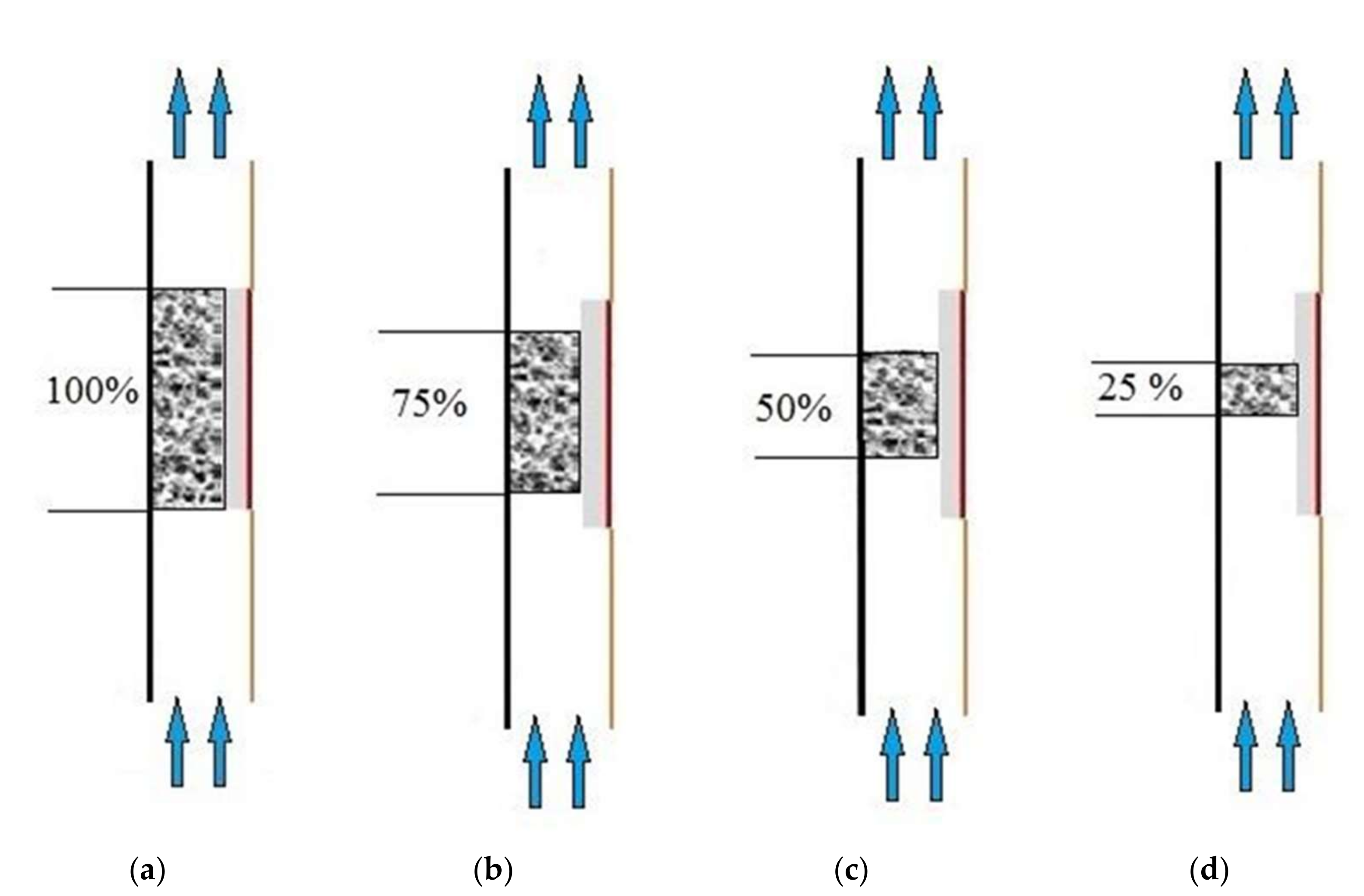
The studied 4 length of the metal foam is also shown in Figure 3. The problem is solved for four cases, 100%, 75%, 50% and 25% length of the metal foam.
The definitions of heat transfer coefficient and Nusselt number in this study are given below.
Heat transfer coefficient:
where
Nusselt number:
where
4. Numerical Details and Grid Independent Study
Sketch of two-dimensional numerical domains for computation is depicted in Figure 2 with described boundary conditions required for numerical modeling of the domain using commercially available ANSYS FLUENT software (Ansys, India). Contact regions of porous, solid and fluid regions are associated with the corresponding interfaces. The experimental domain is symmetric in nature about its axis along the flow direction as can be seen in Figure 1, and therefore, just one part of the symmetrical domain is considered for the numerical modeling that results in decreased computational effort by appropriately incorporating a symmetry boundary condition at the center line axis separating two symmetrical portions. The obtained numerical domain mainly constitutes a heater close to a solid plate of aluminum that faces inward into the channel passage accommodating the foam sample. Evaluation of the required flow and heat transfer influencing properties appearing in the governing equations are estimated as provided in [12,18].
The pressure-based coupled algorithm is used to solve continuity and momentum equations in order to achieve numerically modeled flow domain. The convergence determined by residuals of the solutions in the iterative steps is set as 10−5 for momentum and continuity and 10−10 for energy. A grid independence study was carried out for the numerical domain in the present study comparing the domain with 26,130; 56,700 and 88,400 cells as shown in Table 1. Having the highest cell domain as the base line, it was observed that the percentage deviation of pressure drop and wall temperature are found to be at least 0.07% and 0.42%, respectively, for the meshed domain of 56,700 cells. However, with a lower mesh size of 26,130 cells, the respective percentage deviations of pressure drop and wall temperature were found to be 0.22% and 0.94%, and any further decrease in the number of cells in the meshed domain would increase the deviation of the mentioned heat transfer and flow parameters. Therefore, in the current study for optimum computational effort, a mesh domain with 56,700 elements is chosen, and subsequent simulations were carried out in the same meshed domain throughout the present work.
5. Validation of the Numerical Solution
The numerical procedure involved in the present study is validated against the experimental work of [30]. Variations of numerically predicted thermal parameters, such as wall temperature and wall heat transfer coefficient, with those of Kamath et al.’s [30] experimental data are shown in Figure 4a for 20 PPI and 0.9 porosity porous foam. Similarly, the variation of the numerically simulated and experimentally obtained flow parameter is shown in Figure 4b in terms of variation in pressure drop for a foam sample of 0.9 porosity and 20 PPI. Numerically predicted data of thermal and flow parameters are observed to be in good agreement with that of the experimental work. Maximum percentage deviation of numerically predicted temperature data was found to be only 2.75% from that of experimental value and a 0.048% of minimum deviation was observed between the numerically predicted and experimentally obtained data. Similarly, with good agreement in trend of pressure drop variation, numerically predicted data showed an average percentage deviation of 12%. This confirms the aptness of the current numerical procedure and adopted models to predict flow and temperature field in a domain consisting of metal based porous media.
6. TOPSIS Technique and Various Trade-off Scenarios between Pressure Drop Minimization and Heat Transfer Augmentation Behavior
The TOPSIS technique allows multi-objective optimization to be employed where one objective is to minimize a parameter and, contrarily, another is to maximize the other parameter (in this study, flow resistance and heat transfer are the parameters to be minimized and maximized, respectively) to understand and distinguish the given variable conditions (under various pore density, porosity and thickness conditions) based on various trade-offs between pressure drop and heat transfer. It also makes it possible to know in what trade-off scenario a given variable condition is participating. The knowledge of the trade-off in which a given variable condition would result becomes crucial for designing a heat transfer device where maximization of heat transfer and minimization of pressure drop are of major interest. In that direction, the present work demonstrates various trade-offs (in terms of Criteria I to V) involving variable conditions such as pore density, porosity and thickness of the metal foam that can alter the trade-off between heat transfer and pressure drop.
- Step 1: Obtain matrix of normalized columns.
Produce a matrix of two columns each comprising values of wall heat transfer coefficient (hi1) and values of pressure drop (pi2), respectively. Produce another set of two columns each comprising normalized magnitudes of heat transfer coefficient and pressure drop (h_i3) and (p_i4), respectively, using Equations (17) and (18).
where ‘i’ indices (i = 1, 2, …, m) indicate the rows of the matrix, and ‘m’ represents the total number of metal foam models (pertaining to all variable conditions).
- Step 2: Obtain matrix of weight assigned normalized columns.
Additionally, the matrix is extended with weighted normalized columns, using Equations (19) and (20); the weight of unity is distributed (that varies from 0 to 1) to the formerly computed values of normalized magnitudes of heat transfer coefficient and pressure drop. The allotted weight entirely depends on the particular interest of the design.
where Wh and WP are 0 and 1, respectively, for criteria I, whereas it is 0.25 and 0.75, 0.5 and 0.5, 0.75 and 0.25 and 1 and 0 for criteria II, III, IV and V, respectively. Various criteria and their significance are elaborated in the later discussion.
- Step 3: Obtain the ideal best V+ and ideal worst V− values.
The ideal worst and best values are achieved from the formerly computed weighted normalized columns of pressure drop and the heat transfer coefficient values. Ideal best value (V+) is the highest value in the set of beneficial parameters and the lowest value in the set of unfavorable parameters. Similarly, ideal worst value (V−) is the lowest value in the set of favorable parameters and the highest value in the set of unfavorable parameters. In the present study, since pressure drop is considered as the unfavorable parameter while average heat transfer coefficient is considered as the favorable parameter, the highest value among the weighted normalized columns of pressure drop is regarded as the ideal worst, and the lowest value amongst the weighted normalized column of pressure drop is chosen as the ideal best value. On the other hand, the maximum value among the weighted normalized column of heat transfer coefficient is chosen as the ideal best value, and the lowest value among the weighted normalized column of heat transfer coefficient is considered as the ideal worst value. Identification of the ideal best value V+ and the ideal worst value V− is expressed using the Equations (21)–(24).
- Step 4: Obtain the Euclidean distance.
Euclidean distance refers to the relative distance of each weighted normalized value from the obtained (best or worst) ideal values. Positive Euclidean distance is the measure of distance of each value in the weighted normalized column from the ideal best value and is evaluated as given in Equation (25). Similarly, negative Euclidean distance is the measure of distance of each value in the weighted normalized column from the ideal worst value and is evaluated as given in Equation (26).
- Step 5: Evaluate the performance score.
Performance scores of metal foams of all considered variable conditions are evaluated using Equation (27). It ranks the metal foams subjected to variable conditions (pore density, porosity and thickness) based on the values of the heat transfer coefficient and pressure drop exhibited, under the restriction of how close is its performance in meeting the given weighted criteria.
7. Results and Discussion
7.1. Pressure Drop and Heat Transfer Characteristics
Pressure drop variation is shown in Figure 5 for varying thickness scenarios, each for foam materials of various PPI and porosity blends. It can be observed that for any given thickness of the foam sample considered, pressure drop increases with an increase in pore density for any given porosity condition due to the increased resistance to flow. This is primarily due to the increase in number of metal fibers with the increase in pore density condition, which results in increased flow obstruction leading to an increased pressure drop. Contrarily, the pressure drop intensifies with a decrease in porosity for any given pore density condition. It has to be noted that varied porosity for a given pore density condition is achieved as a result of a compromise in the fiber diameter of the foam samples. In this regard, for a given pore density situation, the porosity of a foam sample is increased as a result of a decrease in the fiber diameter allowing lesser flow obstruction to the flow and, consequently, a lowered pressure drop. For a given pore density condition, porosity decreases with an increase in fiber diameter, resulting in an increased flow resistance and, consequently, increasing the pressure drop. When the thickness of the metal foams is reduced, as an obvious behavior the pressure drop is observed to decrease. The interesting observation can be made from Figure 5 that, although the pressure drop continuously decreases or increases for a given PPI and porosity combination with variation in thickness, a certain pressure drop values can be observed to be close for foam samples of different foam structural properties (pore density and porosity) under varied thickness scenario. Since heat transfer characteristics also vary with the mentioned variables, it would be interesting to analyze what combinations of PPI and porosity of a foam material, under which thickness scenario, are participating in a desired trade-off scenario between curtailing pressure drop and enhancing heat transfer.
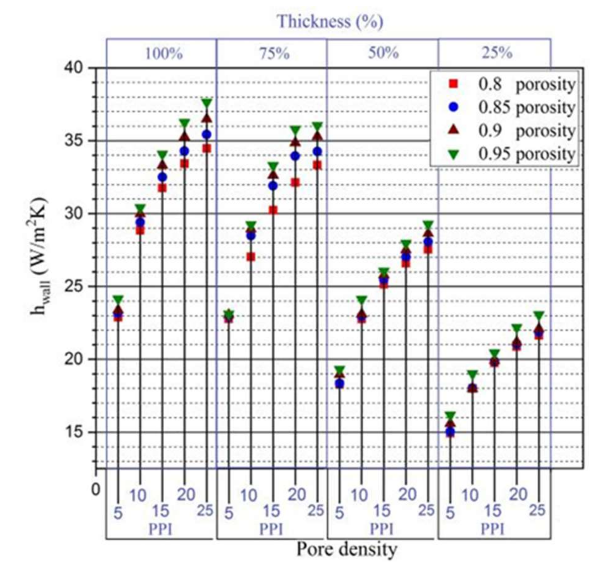
Heat transfer features of the metal foams of considered pore density and porosity combinations with varying thickness condition are shown in Figure 6, in terms of average wall heat transfer coefficient, and in Figure 7, in terms of wall average wall Nusselt number. It can be observed that for any given thickness scenario, the average wall heat transfer coefficient increases with upsurge in pore density for a considered porosity condition as a result of augmented interfacial area density participating in improved heat transfer [12]. Similarly, for a given pore density condition in any thickness scenario considered, the wall heat transfer coefficient is observed to increase with an increase in porosity due to enhanced interfacial heat transfer coefficient as a result of increased fluid volume . This is primarily due to the increased fluid to solid ratio with the increase in porosity enabling more fluid to participate in the heat transfer [12]. It can be seen that the wall heat transfer coefficient increases greatly with an increase in pore density for a given porosity condition compared to the increase in the same coefficient with an upsurge in porosity for a given PPI condition. Interfacial heat transfer is a key feature of heat transfer through a porous medium that contributes to the overall heat transfer in a medium filled with metal foam as porous medium. It is characterized by an interfacial specific surface area (asf) and interfacial heat transfer co-efficient (hsf). The product of these parameters asf × hsf can be seen appearing in the energy equation (Equations (6) and (7)). An increase in pore density with constant porosity increases both asf and hsf, whereas an increase in porosity at constant pore density decreases the interfacial specific surface area and slightly increases interfacial heat transfer coefficient as a result of increased fluid volume in the domain. Owing to these effects, heat transfer characterized by a wall heat transfer co-efficient can be observed to greatly increase with pore density for a given porosity condition compared to its increase with an increase in porosity for a given pore density condition. Considering the variation of wall Nusselt number under the considered variable conditions, a similar trend in relative deviation of wall Nusselt number similar to that of wall heat transfer coefficient is observed. However, Nusselt number is observed to greatly increase with porosity rather than with changes in pore density. Unlike wall heat transfer coefficient behavior, Nusselt number accounts the heat transfer through convection compared to heat transfer that would have resulted through conduction. In this regard, an increase in porosity resulted in a higher Nusselt number with greater magnitude than it would be with an increase in pore density, corresponding to effective thermal conductivity value as described in Equation (12). From the variation of both average wall heat transfer coefficient and average wall Nusselt number, the heat transfer can be perceived to increase with an increase in pore density and as well as with porosity. In addition to this, an increase in heat transfer can be seen with an increase in thickness as an obvious result.
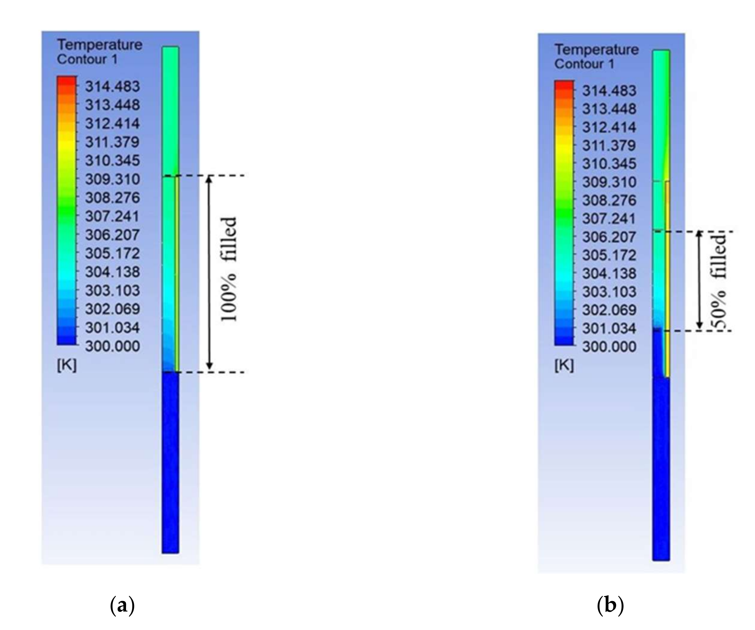
It can be observed that the pressure drop and heat transfer characteristics of metal foams are similar to those of other metal foams subjected to variation in pore density, porosity as well as thickness. For comparison, the pressure contours of 100% thickness and 50% thickness of 0.95 porosity 10 PPI foam are shown in Figure 8a,b. Similarly, temperature contours of 100% thickness and 50% thickness of 0.95 porosity 10 PPI foam are also shown in Figure 9a,b.
Each metal foam of a given pore density and porosity combination under the considered thickness exhibits unique heat transfer and pressure drop characteristics. This raises the interesting question of by what magnitude the pressure drop is compensated to exhibit the corresponding heat transfer behavior. Noting that this trade-off scenario varies with the structural (pore density and porosity) and as well as with configurational (thickness) aspects, a comprehensive analysis attempting to understand the tradeoff mechanism between minimizing pressure drop abilities and maximizing heat transfer characteristics of a metal foam under a given variable condition would be very beneficial in the field of heat transfer involving metal foams.
7.2. TOPSIS Analysis
As a well-known fact, the benefit of an increase in heat transfer is always supplemented by an undesired increased pressure drop with the use of metal foams in heat exchanging applications. It is a long-standing issue which requires attention to arrive at an optimum performance. There are several aspects that determine the exhibited trade-off process in the heat transfer enhancement and pressure drop minimization phenomenon; among them, varying thickness scenario and varying PPI and porosity of foams are the best choice of parameters to include in analyzing the tradeoff process as they can be easily varied. In the present study, varying thickness scenarios of four kinds are considered simultaneously with altering pore densities of five kinds (5, 10, 15, 20 and 25 PPI), each with a combination of various porosities such as 0.8, 0.85, 0.9 and 0.95 porosity. The flow resistance, characterized by pressure drop, and the heat transfer, characterized by average wall heat transfer coefficient and Nusselt number exhibited by the metal foams of the above-mentioned variable conditions, are shown in Figure 5, Figure 6 and Figure 7, respectively. However, none of the mentioned graphs gives information on what is the trade-off in the flow resistance minimization behavior of metal foams in order to exhibit a given heat transfer characteristic. It is here that TOPSIS (technique for order of preference by similarity to ideal solution), a multi-objective, multi-criteria decision-making tool, plays a key role in analyzing which metal foams of given variable condition perform best in meeting a desired trade-off scenario. In other words, the TOPSIS methodology makes it possible to understand how the flow resistance minimization behavior of metal foams is compromised in order to exhibit a given heat transfer behavior subjected to variable conditions such as pore density and porosity of the metal foam and the thickness considered. In this section, the results of TOPSIS analysis on the present problem are presented for various trade-off scenarios (in terms of Criteria I to V) involving variable conditions such as pore density, porosity and thickness of the metal foam that can alter the trade-off between pressure drop and heat transfer.
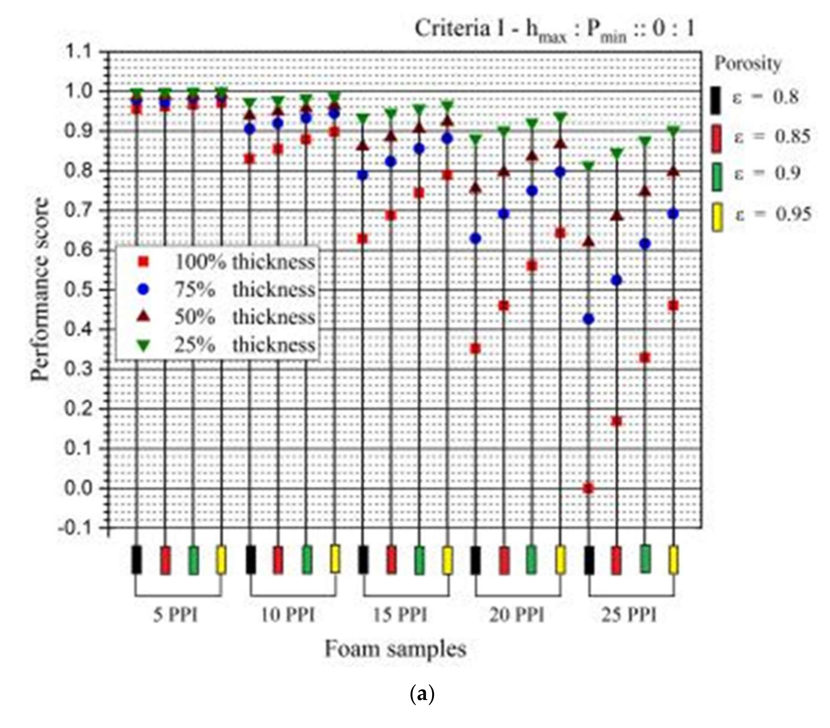
Criteria 1 (hmax:Pmin::0:1 and Numax:Pmin::0:1) represents the trade-off scenario between pressure drop and heat transfer where complete emphasis is given to minimization of pressure drop with no attention given to enhancement of heat transfer. Various performances of metal foams under the considered variable conditions in order to meet the specific weighted objective pertaining to criteria 1 are shown in Figure 10a,b, considering trade-off between pressure drop with wall heat transfer coefficient and Nusselt number, respectively. Under the circumstances of criteria 1, where all the emphasis is focused on minimization of pressure drop (by placing complete weight of ‘1’ on minimizing pressure drop objective) and zero emphasis is given on maximizing heat transfer (by placing weight of ‘0’ on maximizing heat transfer objective), as an obvious interpretation, it can be noted that for a given thickness scenario, metal foams of lower PPI that offer less obstruction to flow are scored best for a given porosity condition. Similarly, for a given thickness scenario, it can be witnessed that for a foam material of a considered pore density, the performance of higher porosity foams is better in relative to lesser porosity foams that offer higher flow resistance. Comparing this performance with varying thickness condition, it can be noted that for any foam material of a given PPI and porosity condition, a better performance is achieved with decrease in thickness as an obvious result of reduced flow resistance accompanying reduced thickness scenario of the metal foams. It is interesting to note that the performance of metal foam of particular pore density and porosity conditions in a given thickness scenario can be closer to the performance of metal foam of a different pore density and porosity combination under a different thickness scenario. This kind of performance charts help choose the desired variable conditions, for instance, thickness of metal foams, where there is restricted variations in pore density and porosity combinations of the metal foams.
Criteria 2 (hmax:Pmin::0.25:0.75 and Numax:Pmin::0.25:0.75) representing the case where slight emphasis is given to heat transfer maximization capabilities of foams (with 25% distributed weight on maximizing heat transfer objective) and still a larger emphasis given to minimizing the pressure drop objective (with 75% distributed weight on this objective) are shown in Figure 11a,b. It can be observed that a 5 PPI foam sample of 25% thickness that performed best in meeting the objectives of criteria 1, performs the worst while subjected to the objectives of criteria 2. However, for other pore density scenarios apart from 5 PPI, the relative deviation of performance scores of foam materials is observed to get closer to that of criteria 1 particularly with an upsurge in the pore density (PPI) condition.
Criteria 3 (hmax:Pmin::0.5:0.5 and Numax:Pmin::0.5:0.5) represents the case where equal emphasis is given to the heat transfer maximization capabilities of foams (with 50% distributed weight on maximizing heat transfer objective) and to minimizing the pressure drop objective (with 50% distributed weight on this objective); the results are shown in Figure 12a,b. It can be perceived that foam samples of 10 PPI pore density with a 75% thickness condition perform the finest in meeting the criteria with an increase in porosity; 50% thickness foam samples of 15 PPI pore density can be observed to outperform 25% thickness foam samples of 15 PPI with a higher porosity condition, unlike the situation in criteria 1 and 2 where 25% thickness foam samples still performed better than foam samples of 50% thickness. The tendency of 50% thickness foam samples of 20 PPI pore density to outperform the 25% thickness scenario can also be observed with a higher porosity condition. With a 5 PPI pore density condition, the 75% and 100% thickness conditions are observed to perform very close to each other. However, in scenarios of higher pore density, such as 25 PPI, the relative deviation of the performance scores of foam samples of considered variable conditions is similar to that of criteria 1 and 2 where a foam material of a given pore density and porosity condition performed best with a 25% thickness condition followed by 50, 75 and 100 percent thickness conditions.
Criteria 4 (hmax:Pmin::0.75:0.25 and Numax:Pmin::0.75:0.25), representing the case where more emphasis is given to the heat transfer maximization capabilities of foams (with 75% distributed weight on maximizing heat transfer objective) and comparatively lesser importance given to minimizing the pressure drop objective (with 25% distributed weight on this objective), are shown in Figure 13a,b. Foam samples of 75% and 100% thickness are observed to closely perform (subject to the objectives of these criteria) under all porosity conditions under 5 PPI and 10 PPI conditions, with the 100% thickness condition showing inclination to perform better than the 75% thickness condition in the highest porosity case. However, this behavior is clearly exhibited under higher pore density conditions such as 15, 20 and 25 PPI where foam samples of 75% thickness can be seen dominating all other thickness scenarios under the highest porosity condition. Variation performance inclinations (either increasing or decreasing behavior) can be seen under varying porosity conditions due to changes in the trade-off scenarios between pressure drop and heat transfer. Moreover, a slight inconsistency in the relative deviation of the performance scores can be observed when analyzing the heat transfer coefficient and Nusselt number as heat transfer parameters. This is because of dissimilar variations in magnitude of the heat transfer coefficient and Nusselt number as shown in Figure 6 and Figure 7, which results in slight variations in the trade-off scenarios with pressure drop (pressure drop being an unaltered parameter both in the comparison with heat transfer coefficient as well as with the Nusselt number).
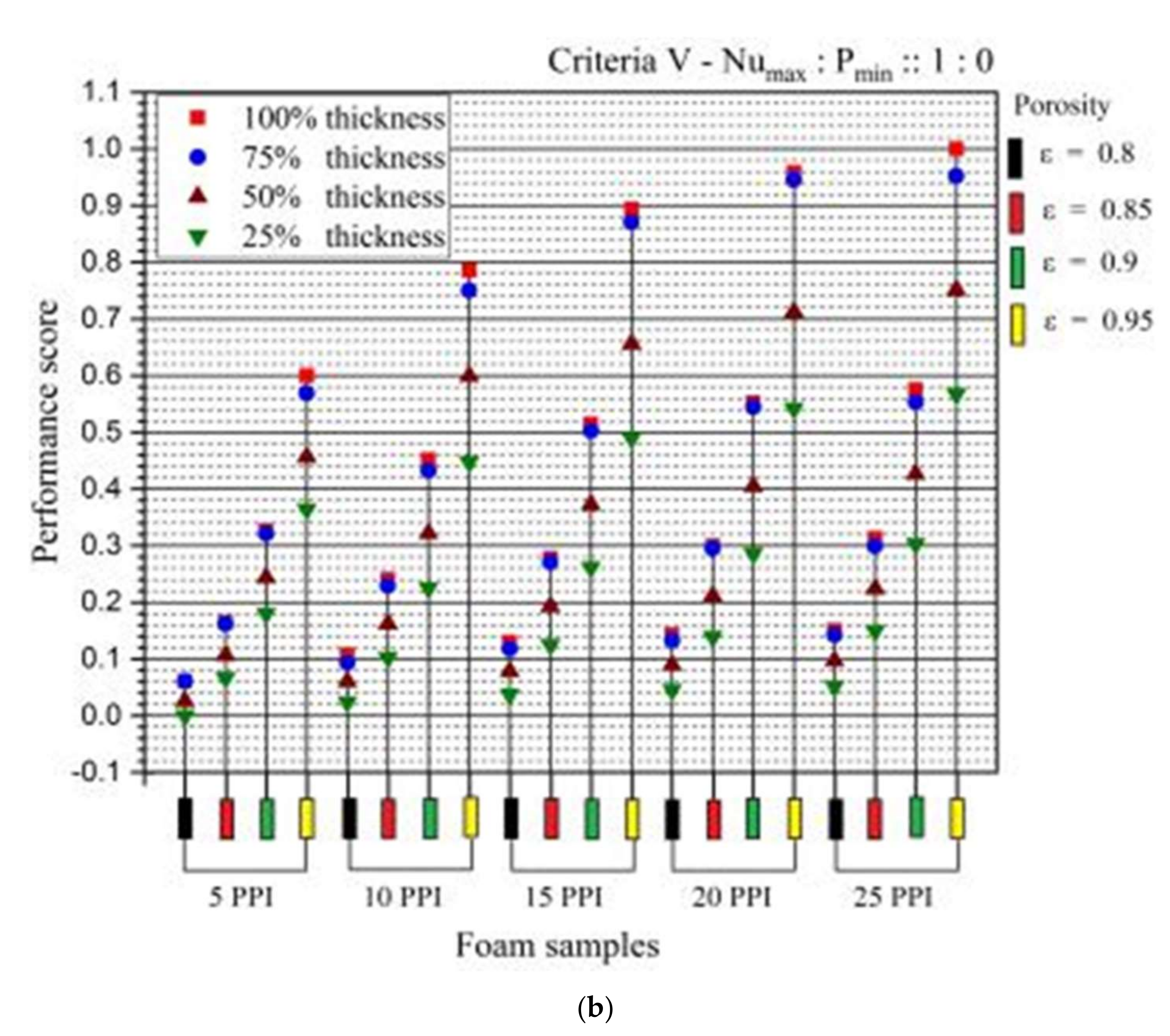
Criteria 5 (hmax:Pmin:: 1:0 and Numax:Pmin:: 1:0), representing the case where the highest emphasis is given to the heat transfer maximization capabilities of foams (with 100% distributed weight on maximizing heat transfer objective) and the least emphasis is given to the objective of minimizing pressure drop (with 25% distributed weight on this objective), are shown in Figure 14a,b. In other words, criteria 5 rank the foam samples subjected to different variable conditions such as variable pore density, porosity and thickness based on complete attention given to maximizing the heat transfer abilities of the foam samples with no attention given to minimization of the pressure drop. Hence, subjected to these criteria, those foams samples of given variable conditions are scored best that exhibit the highest heat transfer irrespective of pressure drop. As it can be observed from Figure 14a,b, for any foam material of a given PPI and porosity, 100% thickness foams perform best in meeting this criterion, followed by 75, 50 and 25% thickness foams. For a given thickness and pore density condition, the performance scores (subjected to the objectives of criteria 5) of foam samples are observed to increase with porosity. In each pore density condition, 100% filled cases with the highest porosity can be seen performing best in meeting these criteria. The highest pore density case with the highest porosity and 100% thickness exhibits the highest heat transfer which can be seen ranked as the best in Figure 14a,b. It can be noted that although the pressure drop is relatively larger in a higher pore density case and a complete thickness case, the case of a completely filled 25 PPI foam is ranked best, considering its highest heat transfer enhancement behavior irrespective of its flow resistance behavior as decided by criteria 5.
From Figure 10a to Figure 14b, it can be noted that every foam sample of given variable conditions (pore density, porosity and thickness) shows a different tendency towards meeting the various criteria (subjected to different objectives of various magnitudes of importance). The variation in relative performance of foams of particular variable condition with changes in criteria shows how differently does a foam sample of particular variable conditions participates in the trade-off between heat transfer and flow resistance. Such analysis not only helps decide which variable conditions to consider for given or desired heat transfer and pressure drop characteristics but also helps judge how well a given condition is participating in the trade-off between heat transfer and pressure drop, which is a crucial point in designing a heat exchanging device especially dealing with metal foam-like materials to enhance heat transfer that always comes with a penalty of increased pressure drop in a thermal system.
8. Conclusions
A critical analysis of various trade-off scenarios between heat transfer and pressure drop involving metal foams has been accomplished in the present study. For this purpose, metal foams of three prime variable conditions including pore density (5, 10, 15, 20 and 25 PPI), porosity (0.8, 0.85, 0.9 and 0.95 porosity) and thickness (100, 75, 50 and 25 percent) were considered in a vertical channel subjected to a constant heat flux condition. Individually analysis showed that heat transfer characteristics increased with pore density, porosity and thickness of the foam sample as expected. Moreover, the pressure drop was observed to decrease with a decrease in the pore density and thickness conditions and with an increase in porosity. As per the authors’ best knowledge, this is the first time that both flow resistance and heat transfer characteristics are simultaneously analyzed for foam samples of three orderly varying variable conditions, namely, pore density, porosity and thickness, under different objectives (one is to maximize heat transfer and another to minimize pressure drop) subjected to various magnitudes of importance, to understand various trade-off scenarios in which a foam sample of given variable conditions would participate. Interesting trade-off scenarios between the enhancement of heat transfer and the reduction of flow resistance behavior were demonstrated using TOPSIS, a multi-objective multi-criteria decision-making tool that comprehensively illustrates various potentials of every foam sample of considered variable conditions in meeting desired trade-off conditions.
The criteria of hmax:Pmin and Numax:Pmin is used to represent the trade-off scenario between pressure drop and heat transfer. For the criteria of hmax:Pmin::0:1 and Numax:Pmin::0:1, metal foam with 5 PPI, 25% thickness yields the best score. For the criteria of hmax:Pmin::0.5:0.5 and Numax:Pmin::0.5:0.5, the best score belongs to the metal foam with 10 PPI, 75% thickness with porosity of 0.95. The metal foam with 25 PPI, 100% thickness with porosity of 0.95 received the best score for the criteria of hmax:Pmin::1.0:0.0 and Numax:Pmin::1.0:0.0.
The selection of the best pore density, thickness and porosity depends on the criteria representing the trade-off between the pressure drop and heat transfer. A score given by the TOPSIS method can deduce the best configurational and structural parameters for a specified application.
Author Contributions
Conceptualization, T.G. and N.G.; methodology, T.G., N.G. and M.M.; software, T.G. and N.G.; validation, T.G. and N.G.; formal analysis, T.G. and N.G.; investigation, T.G., N.G. and M.M.; resources, T.G. and N.G.; data curation, T.G.; writing—original draft preparation, T.G.; writing—review and editing, T.G., N.G. and M.M.; visualization, T.G.; supervision, N.G. and M.M.; project administration, T.G. and N.G.; funding acquisition, N.G. All authors have read and agreed to the published version of the manuscript.
Funding
This research was funded by Science and Engineering Research Board (SERB), Department of Science and Technology, India. Grant number EEQ/2018/000322.
Institutional Review Board Statement
Not applicable.
Informed Consent Statement
Not applicable.
Data Availability Statement
Not applicable.
Acknowledgments
Science and Engineering Research Board (SERB), DST No: EEQ/2018/000322, India, supported and funded this work.
Conflicts of Interest
The authors declare no conflict of interest. The funders had no role in the design of the study; in the collection, analyses or interpretation of data; in the writing of the manuscript or in the decision to publish the results.
Nomenclature
| asf | Area density (m−1) |
| C | Inertial resistance coefficient (m−1) |
| Cp | Specific heat (J/kgK) |
| dp | Pore diameter (m) |
| df | Fiber diameter (m) |
| h | Heat transfer coefficient (W/m2K) |
| hsf | Interstitial heat transfer coefficient (W/m2K) |
| K | Permeability (m2) |
| Nu | Nusselt number |
| P | Pressure (N/m2) |
| Pi | Performance index |
| Pr | Prandtl number of fluid |
| Re | Reynolds number |
| S | Euclidean distance |
| T | Temperature (K) |
| u | Velocity vector (m/s) |
| v | Velocity at inlet (m/s) |
| Greek symbols | |
| ε | Porosity |
| ω | pore density |
| λ | Thermal conductivity (W/mK) |
| μ | Dynamic viscosity (N-s/m2) |
| v | Kinematic viscosity (m2/s) |
| ρ | Density (kg/m3) |
| Subscript | |
| f | Fluid |
| fe | Fluid effective |
| s | Solid |
| se | Solid effective |
References
- Brahim, T.; Jemni, A. CFD analysis of hotspots copper metal foam flat heat pipe for electronic cooling applications. Int. J. Therm. Sci. 2021, 159, 106583. [Google Scholar] [CrossRef]
- Mahjoob, S.; Kashkuli, S. Thermal Transport Analysis of Injected Flow through Combined Rib and Metal Foam in Converging Channels with Application in Electronics Hotspot Removal. Int. J. Heat Mass Transf. 2021, 177, 121223. [Google Scholar] [CrossRef]
- Qureshi, Z.A.; Al-Omari, S.A.B.; Elnajjar, E.; Al-Ketan, O.; Al-Rub, R.A. Using triply periodic minimal surfaces (TPMS)-based metal foams structures as skeleton for metal-foam-PCM composites for thermal energy storage and energy management applications. Int. Commun. Heat Mass Transf. 2021, 124, 105265. [Google Scholar] [CrossRef]
- Talebizadehsardari, P.; Mohammed, H.I.; Mahdi, J.M.; Gillott, M.; Walker, G.S.; Grant, D.; Giddings, D. Effect of airflow channel arrangement on the discharge of a composite metal foam-phase change material heat exchanger. Int. J. Energy Res. 2021, 45, 2593–2609. [Google Scholar] [CrossRef]
- Mahdi, J.M.; Pal Singh, R.; Taqi Al-Najjar, H.M.; Singh, S.; Nsofor, E.C. Efficient thermal management of the photovoltaic/phase change material system with innovative exterior metal-foam layer. Sol. Energy 2021, 216, 411–427. [Google Scholar] [CrossRef]
- Heyhat, M.M.; Mousavi, S.; Siavashi, M. Battery thermal management with thermal energy storage composites of PCM, metal foam, fin and nanoparticle. J. Energy Storage 2020, 28, 101235. [Google Scholar] [CrossRef]
- Liu, H.; Ahmad, S.; Shi, Y.; Zhao, J. A parametric study of a hybrid battery thermal management system that couples PCM/copper foam composite with helical liquid channel cooling. Energy 2021, 231, 120869. [Google Scholar] [CrossRef]
- Mohammed, H.I.; Sardari, P.T.; Giddings, D. Multiphase flow and boiling heat transfer modelling of nanofluids in horizontal tubes embedded in a metal foam. Int. J. Therm. Sci. 2019, 146, 106099. [Google Scholar] [CrossRef]
- Heyhat, M.M.; Valizade, M.; Abdolahzade, S.; Maerefat, M. Thermal efficiency enhancement of direct absorption parabolic trough solar collector (DAPTSC) by using nanofluid and metal foam. Energy 2020, 192, 116662. [Google Scholar] [CrossRef]
- Saedodin, S.; Zamzamian, S.A.H.; Nimvari, M.E.; Wongwises, S.; Jouybari, H.J. Performance evaluation of a flat-plate solar collector filled with porous metal foam: Experimental and numerical analysis. Energy Convers. Manag. 2017, 153, 278–287. [Google Scholar] [CrossRef]
- Kotresha, B.; Gnanasekaran, N. Effect of thickness and thermal conductivity of metal foams filled in a vertical channel—A numerical study. Int. J. Numer. Methods Heat Fluid Flow 2019, 29, 184–203. [Google Scholar] [CrossRef]
- Trilok, G.; Gnanasekaran, N. Numerical study on maximizing heat transfer and minimizing flow resistance behavior of metal foams owing to their structural properties. Int. J. Therm. Sci. 2021, 159, 106617. [Google Scholar] [CrossRef]
- Singh, P.; Nithyanandam, K.; Zhang, M.; Mahajan, R.L. The effect of metal foam thickness on jet array impingement heat transfer in high-porosity aluminum foams. J. Heat Transf. 2020, 142, 052301. [Google Scholar] [CrossRef]
- Kotresha, B.; Gnanasekaran, N. Investigation of Mixed Convection Heat Transfer Through Metal Foams Partially Filled in a Vertical Channel by Using Computational Fluid Dynamics. J. Heat Transfer 2018, 140, 112501. [Google Scholar] [CrossRef]
- Jadhav, P.H.; Gnanasekaran, N.; Perumal, D.A.; Mobedi, M. Performance evaluation of partially filled high porosity metal foam configurations in a pipe. Appl. Therm. Eng. 2021, 194, 117081. [Google Scholar] [CrossRef]
- Ambrosio, G.; Bianco, N.; Chiu, W.K.S.; Iasiello, M.; Naso, V.; Oliviero, M. The effect of open-cell metal foams strut shape on convection heat transfer and pressure drop. Appl. Therm. Eng. 2016, 103, 333–343. [Google Scholar] [CrossRef] [Green Version]
- Donmus, S.; Mobedi, M.; Kuwahara, F. Double-layer metal foams for further heat transfer enhancement in a channel: An analytical study. Energies 2021, 14, 672. [Google Scholar] [CrossRef]
- Trilok, G.; Kumar, K.K.; Gnanasekaran, N.; Mobedi, M. Numerical assessment of thermal characteristics of metal foams of orderly varied pore density and porosity under different convection regimes. Int. J. Therm. Sci. 2022, 172, 107288. [Google Scholar] [CrossRef]
- Zuo, H.; Wu, M.; Zeng, K.; Zhou, Y.; Kong, J.; Qiu, Y.; Lin, M.; Flamant, G. Numerical investigation and optimal design of partially filled sectorial metal foam configuration in horizontal latent heat storage unit. Energy 2021, 237, 121640. [Google Scholar] [CrossRef]
- Sardari, P.T.; Mohammed, H.I.; Giddings, D.; Walker, G.S.; Gillott, M.; Grant, D. Numerical study of a multiple-segment metal foam-PCM latent heat storage unit: Effect of porosity, pore density and location of heat source. Energy 2019, 189, 116108. [Google Scholar] [CrossRef]
- Mohammed, H.I.; Talebizadehsardari, P.; Mahdi, J.M.; Arshad, A.; Sciacovelli, A.; Giddings, D. Improved melting of latent heat storage via porous medium and uniform Joule heat generation. J. Energy Storage 2020, 31, 101747. [Google Scholar] [CrossRef]
- Chen, S.; Li, W.; Mohammed, H.I. Heat transfer of large Prandtl number fluids in porous media by a new lattice Boltzmann model. Int. Commun. Heat Mass Transf. 2021, 122, 105129. [Google Scholar] [CrossRef]
- Li, Y.; Wang, S.; Zhao, Y. Experimental study on heat transfer enhancement of gas tube partially filled with metal foam. Exp. Therm. Fluid Sci. 2018, 97, 408–416. [Google Scholar] [CrossRef]
- Bianco, N.; Iasiello, M.; Mauro, G.M.; Pagano, L. Multi-objective optimization of finned metal foam heat sinks: Tradeoff between heat transfer and pressure drop. Appl. Therm. Eng. 2021, 182, 116058. [Google Scholar] [CrossRef]
- Siavashi, M.; Talesh Bahrami, H.R.; Aminian, E. Optimization of heat transfer enhancement and pumping power of a heat exchanger tube using nanofluid with gradient and multi-layered porous foams. Appl. Therm. Eng. 2018, 138, 465–474. [Google Scholar] [CrossRef]
- Shikh Anuar, F.; Ashtiani Abdi, I.; Odabaee, M.; Hooman, K. Experimental study of fluid flow behaviour and pressure drop in channels partially filled with metal foams. Exp. Therm. Fluid Sci. 2018, 99, 117–128. [Google Scholar] [CrossRef]
- Lai, Z.; Hu, H.; Ding, G. Influence of pore density on heat transfer and pressure drop characteristics of wet air in hydrophilic metal foams. Appl. Therm. Eng. 2019, 159, 113897. [Google Scholar] [CrossRef]
- Sun, M.; Hu, C.; Zha, L.; Xie, Z.; Yang, L.; Tang, D.; Song, Y.; Zhao, J. Pore-scale simulation of forced convection heat transfer under turbulent conditions in open-cell metal foam. Chem. Eng. J. 2020, 389, 124427. [Google Scholar] [CrossRef]
- Mancin, S.; Zilio, C.; Rossetto, L.; Cavallini, A. Foam height effects on heat transfer performance of 20 ppi aluminum foams. Appl. Therm. Eng. 2012, 49, 55–60. [Google Scholar] [CrossRef]
- Kamath, P.M.; Balaji, C.; Venkateshan, S.P. Experimental investigation of flow assisted mixed convection in high porosity foams in vertical channels. Int. J. Heat Mass Transf. 2011, 54, 5231–5241. [Google Scholar] [CrossRef]
- Calmidi, V.V.; Mahajan, R.L. Forced convection in high porosity metal foams. J. Heat Transfer 2000, 122, 557–565. [Google Scholar] [CrossRef]
- Zukauskas, A. Convective heat transfer in cross flow. In Handbook of Single-Phase Convective Heat Transfer; John Wiley & Sons: Hoboken, NJ, USA, 1987. [Google Scholar]
- Jadhav, P.H.; Trilok, G.; Gnanasekaran, N.; Mobedi, M. Performance score based multi-objective optimization for thermal design of partially filled high porosity metal foam pipes under forced convection. Int. J. Heat Mass Transf. 2022, 182, 121911. [Google Scholar] [CrossRef]
Figure 1.
Sketch depicting the front view of the experimental set up used in [9] which has a depth of 250 mm. It is mainly constituted by the following: (1) vertical channel, (2) metal foam, (3) aluminum plate and (4) heater.
Figure 1.
Sketch depicting the front view of the experimental set up used in [9] which has a depth of 250 mm. It is mainly constituted by the following: (1) vertical channel, (2) metal foam, (3) aluminum plate and (4) heater.

Figure 2.
Sketch of complete thickness (100% foam filled) numerical domain with assigned boundary conditions.
Figure 2.
Sketch of complete thickness (100% foam filled) numerical domain with assigned boundary conditions.

Figure 3.
Sketch depicting the various thickness configurations considered in the present study: (a) 100% thickness, (b) 75% thickness, (c) 50% thickness and (d) 25% thickness.
Figure 3.
Sketch depicting the various thickness configurations considered in the present study: (a) 100% thickness, (b) 75% thickness, (c) 50% thickness and (d) 25% thickness.

Figure 4.
(a) Assessment of closeness of numerically predicted thermal parameters (wall heat transfer coefficient and wall temperature) for metal foam of 0.9 porosity and 20 PPI with that of experimental data. (b) Assessment of closeness of numerically predicted flow parameters (pressure drop) for metal foam of 0.9 porosity and 20 PPI with that of experimental data.

Figure 5.
Variation of pressure drop for varying thickness scenario at various pore density and porosity conditions.
Figure 5.
Variation of pressure drop for varying thickness scenario at various pore density and porosity conditions.

Figure 6.
Variation of wall heat transfer coefficient for varying thickness scenarios at various pore density and porosity conditions.
Figure 6.
Variation of wall heat transfer coefficient for varying thickness scenarios at various pore density and porosity conditions.

Figure 7.
Variation of wall Nusselt number for varying thickness scenarios at various pore density and porosity conditions.
Figure 7.
Variation of wall Nusselt number for varying thickness scenarios at various pore density and porosity conditions.

Figure 8.
(a) Pressure contours of 100% thickness of 0.95 porosity 10 PPI foam. (b) Pressure contours of 50% thickness of 0.95 porosity 10 PPI foam.
Figure 8.
(a) Pressure contours of 100% thickness of 0.95 porosity 10 PPI foam. (b) Pressure contours of 50% thickness of 0.95 porosity 10 PPI foam.

Figure 9.
(a) Temperature contours of 100% thickness of 0.95 porosity 10 PPI foam. (b) Temperature contours of 50% thickness of 0.95 porosity 10 PPI foam.
Figure 9.
(a) Temperature contours of 100% thickness of 0.95 porosity 10 PPI foam. (b) Temperature contours of 50% thickness of 0.95 porosity 10 PPI foam.

Figure 10.
(a) Criteria I (hmax:Pmin). (b) Criteria I (Numax:Pmin).


Figure 11.
(a) Criteria II (hmax:Pmin). (b) Criteria II (Numax:Pmin).


Figure 12.
(a) Criteria III (hmax:Pmin). (b) Criteria III (Numax:Pmin).

Figure 13.
(a) Criteria IV (hmax:Pmin). (b) Criteria IV (Numax:Pmin).

Figure 14.
(a) Criteria V (hmax:Pmin). (b) Criteria V (Numax:Pmin).


Table 1.
Grid independence study.
| Mesh Type | No. of Elements | Pressure Drop ∆P, N/m2 | Temperature Difference ∆T °C | Deviations ∆P, % | Deviations ∆T, % |
|---|---|---|---|---|---|
| 1 | 26,130 | 27.60 | 7.74 | 0.22 | 0.94 |
| 2 | 56,700 | 27.56 | 7.70 | 0.07 | 0.42 |
| 3 | 88,400 | 27.54 | 7.66 | Base line | |
Publisher’s Note: MDPI stays neutral with regard to jurisdictional claims in published maps and institutional affiliations. |
© 2021 by the authors. Licensee MDPI, Basel, Switzerland. This article is an open access article distributed under the terms and conditions of the Creative Commons Attribution (CC BY) license (https://creativecommons.org/licenses/by/4.0/).
Share and Cite
MDPI and ACS Style
G, T.; Gnanasekaran, N.; Mobedi, M. Various Trade-Off Scenarios in Thermo-Hydrodynamic Performance of Metal Foams Due to Variations in Their Thickness and Structural Conditions. Energies 2021, 14, 8343. https://doi.org/10.3390/en14248343
AMA Style
G T, Gnanasekaran N, Mobedi M. Various Trade-Off Scenarios in Thermo-Hydrodynamic Performance of Metal Foams Due to Variations in Their Thickness and Structural Conditions. Energies. 2021; 14(24):8343. https://doi.org/10.3390/en14248343
Chicago/Turabian StyleG, Trilok, N Gnanasekaran, and Moghtada Mobedi. 2021. "Various Trade-Off Scenarios in Thermo-Hydrodynamic Performance of Metal Foams Due to Variations in Their Thickness and Structural Conditions" Energies 14, no. 24: 8343. https://doi.org/10.3390/en14248343
Note that from the first issue of 2016, this journal uses article numbers instead of page numbers. See further details here.