
Performance and Emission Optimisation of an Ammonia/Hydrogen Fuelled Linear Joule Engine Generator

1
Department of Mechanical Engineering, School of Engineering, University of Birmingham, Birmingham B15 2TT, UK
2
Department of Engineering, Durham University, Durham DH1 3LE, UK
*
Author to whom correspondence should be addressed.
Energies 2024, 17(6), 1490; https://doi.org/10.3390/en17061490
Submission received: 22 January 2024
/
Revised: 3 March 2024
/
Accepted: 18 March 2024
/
Published: 21 March 2024
(This article belongs to the Section A5: Hydrogen Energy)
Abstract
:This paper presents a Linear Joule Engine Generator (LJEG) powered by ammonia and hydrogen co-combustion to tackle decarbonisation in the electrification of transport propulsion systems. A dynamic model of the LJEG, which integrates mechanics, thermodynamics, and electromagnetics sub-models, as well as detailed combustion chemistry analysis for emissions, is presented. The dynamic model is integrated and validated, and the LJEG performance is optimised for improved performance and reduced emissions. At optimal conditions, the engine could generate 1.96 kWe at a thermal efficiency of 34.3% and an electrical efficiency of 91%. It is found that the electromagnetic force of the linear alternator and heat addition from the external combustor and engine valve timing have the most significant influences on performance, whereas the piston stroke has a lesser impact. The impacts of hydrogen ratio, oxygen concentration, inlet pressure, and equivalence ratio of ammonia-air on nitric oxide (NO) formation and reduction are revealed using a detailed chemical kinetic analysis. Results indicated that rich combustion and elevated pressure are beneficial for NO reduction. The rate of production analysis indicates that the equivalence ratio significantly changes the relative contribution among the critical NO formation and reduction reaction pathways.
1. Introduction
Many efforts have been made to improve combustion-based powertrain technology’s efficiency and explore direct applications of zero-carbon alternative fuels to reduce Greenhouse Gas (GHG) emissions. The powertrain’s electrification, which enables optimal use of thermal engines and electric motors, is considered the key pathway to higher energy efficiency [1]. While improvements on conventional crankshaft internal combustion engines are widely investigated to address decarbonisation and electrification in transport propulsion systems, an innovative Linear Joule Engine Generator (LJEG), which couples a linear engine and a linear generator, has recently received attention due to its flexibility on alternative fuels. In contrast to conventional Internal Combustion Engines, linear engines without crankshafts exhibit simpler and more compact structures, reduced friction losses, increased control flexibility, and broader fuel adaptability [2]. The integration with a linear alternator effectively controls the linear engine to run in its optimal working condition [2]. Most research on the LJEG has focused on optimal designs, including dynamics and engine−generator integration, while comprehensive studies on LJEGs fuelled by ammonia or a blend of ammonia and hydrogen are limited. This study presents and validates a comprehensive LJEG dynamic model with the first-generation LJEG lab-scale prototype to investigate the complex interactions between different sub-systems governed by dynamics, thermodynamics, electromagnetics, and combustion chemistry. This study focuses on performance enhancement and the identification of critical associating parameters. As ammonia combustion has received criticism for its flammability and emissions, ammonia combustion robustness is carefully scrutinised and improved by blending hydrogen into fuel and increasing the oxidiser’s oxygen content. Particular attention is paid to NO emissions from the ammonia/hydrogen co-combustion to reveal the impacts of various input parameters using chemical kinetic analysis. Detailed performance enhancement and emission mitigation guidance will be summarised for further prototype development.
1.1. Linear Engine Generators
The linear engine−generator concept has attracted significant attention lately, as different research teams worldwide have developed the idea into various prototypes in recent years [3,4]. A research group at Toyota [5] introduced a single-piston free-piston engine generator. Through one-dimensional cycle simulation, they demonstrated the capability to achieve an electric power output of 10 kW using either premixed charge compression ignition or spark ignition (SI) combustion modes. A prototype was created and demonstrated stable operation, with cycle variations indicating an effective pressure that fell consistently below 3%. Researchers from Tongji University [6] conducted a simulation study on a single-piston spark ignition linear engine. The study results indicated that 7.42 kW electric power output and a system efficiency of 26.1% could be achieved at a brake-specific gasoline fuel consumption of 313.4 g/kWh. Huang [7] presented a dynamic and thermodynamic model of an opposed-piston free-piston generator. The simulation results revealed an average electric power output of 15 kW, with an impressive overall efficiency of 42.5%. Zhang et al. [8] examined the impact of varying compression ratios (CR) and stroke-to-bore (S/B) ratios on the operational performance of a dual-piston free-piston engine generator in their investigation. The results indicated that the optimal power of 4.1 kW was achieved when the S/B ratio was 0.84 at a CR of 10. The findings indicate that an increased S/B ratio and CR contribute to enhanced fuel economy and thermal efficiency in the design. Notably, these improvements persist even when the periodic energy input remains constant. An examination of the engine’s optimal working conditions during cold starts, as reported in a previous study [9], revealed that the targeted CR holds paramount importance during this phase, with frequency exerting a comparatively negligible impact. The Sandia National Laboratory [10] designed a single-cylinder, opposed-piston, free-piston linear generator with potential applications in hybrid electric vehicle systems. The prototype employed hydrogen in homogeneous charge compression ignition combustion, with a CR spanning from 20:1 to 70:1. The indicated efficiency varied between 50% and 55%, encountering challenges in the precise control of certain engine parameters.
The above-mentioned linear engine generators are based on internal combustion engine technologies, focusing on linear engine feasibility and thermal/indicated efficiency improvement. Some designs of the externally powered free-piston engine have been proposed in recent years. Mikalsen and Roskilly proposed one of the first designs of the externally powered free-piston engine for small-scale combined heat-and-power applications [11]. The engine operated on a recuperated Joule Cycle, which employed external steady flow combustion, thus having multi-fuel capability over its counterparts. A team from Jilin University proposed a superheated vapour-powered free-piston compressor [12,13]. The engine focused on harnessing waste heat from the exhaust gas that a stationary compressed natural gas-powered compressor produces, with its primary function being to compress natural gas. The free-piston expander propelled the free-piston compressors, fuelled by superheated vapour injected into both sides. Results from parametric sweeps indicated optimal performance when the expander area ratio to the compressor area was set at 2.5 and the compressor output pressure was maintained at 11 bar. Ndame and Stouffs introduced an open-cycle air-standard liquid piston engine designed for solar energy conversion and waste heat recovery [14]. The system consists of two reciprocating Joule Cycle engines operating in phase opposition. Simulation results revealed that an expander inlet temperature of 633 K, a pressure ratio of 3, and an engine speed of 37.8 rpm led to an efficiency exceeding 35%. Researchers from Newcastle University developed a prototype of the air-standard open cycle LJEG [2], with the simulation results indicating a power output of 4.4 kWe and thermal efficiency of 34%. Investigation under various working conditions identified the electric load, valve timing and pressure ratio as the vital adjustable parameters [2]. Results identified the pressure ratio as the most influential parameter that affected the power output, and the electric load was identified as the main parameter in maximising the electricity generation efficiency. A semi-closed-loop version of the LJEG was proposed in [15], with the design incorporating noble gas as the working fluid and utilising hydrogen for heat input. Examination of various parameters indicated that extending the intake duration increased power output, albeit at decreased efficiency. Efficiency increased with a compressor/expander diameter ratio (CEDR), and the power output relationship with CEDR depended on the exhaust duration. Operating temperature sensitivity for optimal performance depended on valve timings [16].
Much of published research on externally powered free-piston technology is centred on engine development and performance prediction, with little detailed analysis of the fuel type for heat addition. The utilisation of zero-carbon fuels (hydrogen) in the works discussed in references [15,16] differs from the approach presented in this paper. The referenced works operated in semi-closed loops [15], closed loops [16], or utilised noble gases as the working fluids, whereas the proposed work operates on an open loop, using air as the working fluid, and employs ammonia/hydrogen as the power source. Limited research efforts are made using ammonia fuel and scrutinising the relationship between the generator and engine. This research seeks to address this gap by proposing a blend of ammonia and hydrogen fuels for heat addition to eliminate carbon emissions and investigate the linear generator’s interaction with the linear engine.
1.2. Ammonia as a Fuel
Hydrogen fuel is widely accepted as one of the zero-carbon alternative fuels. However, major challenges in the economic viability of its production, storage and transportation must be tackled before its extensive commercial uptake can be achieved [17]. In the meantime, ammonia has received favourable consideration and has been considered a promising hydrogen carrier and a zero-carbon fuel itself [18]. It has a higher gravimetric and volumetric hydrogen density than other hydrogen carriers [19]. Additionally, industrial ammonia production, storage, transportation, and utilisation are well established [18]. The major obstacles to ammonia being widely applied in combustion technologies are its combustion instability and NOx emissions [18]; however, efforts have been made to understand ammonia’s combustion characteristics to offer valuable guidance for its practical application. Experimental and simulation studies have been conducted to investigate ammonia’s ignition [20], flame stability [21], and flame velocity and emissions [22]. Enhancing robustness in zero-carbon ammonia combustion was best achieved by introducing hydrogen and augmenting oxygen content within the oxidiser, as outlined in [23]. It has also been found that the production and consumption of NOx in ammonia combustion are influenced by several factors, such as equivalence ratio, intake fuel/oxidiser temperature, pressure, and fuel additives [18]. Research has been conducted on using ammonia directly on conventional internal combustion engines. Frigo et al. [24] experimented on SI engines fuelled by ammonia and hydrogen. While NOx emissions were not listed as a problem, some degradation of engine power was observed. The examination of an ammonia/dimethyl ether-fuelled engine employing a modified injection strategy [25] revealed that elevated ammonia ratios in the fuel led to a decline in engine power and stability, as well as an increase in NOx emissions. The combustion conditions in an LJEG are different than those in the internal combustion engine; as stated, the innovative LJEG external combustion technology has some measures to deal with ammonia combustion instability and NOx emissions due to steady external heat addition.
2. Configuration of an Ammonia/Hydrogen Fuelled LJEG
Figure 1 illustrates the schematic of the LJEG. The double-acting pistons are utilised to achieve enhanced and smooth power output in both the expander and compressor assemblies. A customised moving magnet tubular linear alternator is positioned between the expander and compressor. The expander’s intake and exhaust flow are regulated by two sets of in-house designed electromagnetic valve trains to guarantee fast and precise management of the gas exchange process. Considering the slow combustion of ammonia, external combustion is applied to avoid intermittent combustion, which is beneficial for robust ammonia combustion. The fuel composition and mass flow rate are regulated based on the required heat input. The dimensions of the LJEG rig are listed in Table 1. The working fluid (air in the current study) from the combustor enters through the left expander inlet valve and pushes the piston to drive the alternator and compressor. The opening distance of the intake valve is feedback-controlled, with the operating stroke length being the target. An optical linear encoder, the primary control input, provides accurate real-time displacement. The Joule Cycle engine’s inherent characteristics require heat transfer from the combustor to the working fluid under a quasi-steady pressure.
After closing the intake valve, the cylinder’s air will further expand to complete the expansion process. Meanwhile, the air compresses within the right-hand side compressor until the pressure difference across the exhaust reed valve exceeds its cracking pressure. Then, the compressed air will be expelled into the combustor unit through the exhaust valve under quasi-steady pressure, where the energy content is increased to drive the expander in the next stroke. Simultaneously, the expander and compressor on the opposite side undergo an exhaust and intake process. As the exhaust valve is closed, an air spring is formed within the cylinder, contributing to the piston’s deceleration. Because double-acting pistons are used, the expansion and compression process occurs within every stroke, as does the generator’s electricity. The motion of the LJEG is governed by the interplay of gas, electromagnetic, and friction forces in the absence of a rigid crankshaft. Any factors that influence gas forces, such as the gas exchange process and combustion, will lead to variation in system dynamics, which in turn cause a change in electromagnetic force and friction force. Therefore, robust control of electromagnetic valves and combustor units is essential to ensure stable and efficient operation.
3. Methods
A LJEG model is coupled to aid LJEG system investigation, integrating multiple simulation sub-models. While each sub-model focuses on examining specific aspects, the intricate interplay among various factors and their impact on the LJEG system is captured by coupling these sub-models. The structural configuration of the coupled LJEG model is illustrated in Figure 2.
The LJEG dynamic model, which couples the linear engine and alternator, is integrated using Simcenter Amesim v2304, a one-dimensional multi-domain modelling and simulation package that serves as the base modelling platform. It considers all the forces influencing the moving mass and computes the kinetic parameters. The piston motion of an LJEG is determined by the interaction among gas forces within the expander and compressor (Fg), alternator electromagnetic force (Fa), and friction force (Ff), as represented in Equation (1). The gas forces originate from the pressure of the gas within the cylinder, following the principles of the first law of thermodynamics, as outlined in Equation (2). Where p denotes in-cylinder pressure, Q represents heat flow across the cylinder wall, refers to the working fluid specific heat ratio, V represents the volume of the in-cylinder, denotes mass flow rate, and is the enthalpy of the inlet or outlet flow, respectively.
Since external combustion is applied, the heat flow across the cylinder wall in Equation (2) is the heat loss from in-cylinder working fluid to the ambient environment. The overall heat transfer coefficient is derived considering the whole pathway, i.e., convection between working fluid and cylinder/pipe inner wall, thermal conduction within the cylinder wall, and natural convection between the cylinder/pipe outer wall and ambient air. Woschni’s correlation is applied for an in-cylinder convective heat transfer coefficient calculation. The heat exchange that occurs within the pipe between the working fluid and the ambient is also considered by referring to an empirical correlation based on exhaust-pipe-heat transfer [26], as indicated in Equations (3)–(6).
where h represents the convective heat transfer coefficient (subscripts i, o, cyl and pipe denote inside, outside, cylinder, and pipe, respectively). Notably, indicates the overall heat transfer coefficient, Aht denotes the heat transfer area, T denotes temperature (subscripts g, w and 0 represent gas, wall and environment, respectively), d is wall thickness, k denotes wall thermal conductivity, D represents the cylinder bore diameter, Re is the Reynolds number, and Nu represents the Nusselt number, respectively.
Heat input to the linear engine is generated from ammonia combustion, which is regulated by adjusting the fuel/air composition. The mass flow rates under specific inlet temperature and pressure conditions are regulated according to the required heat input. The Perfectly Stirred Reactor module in the Ansys Chemkin 2023 R1 software simulates the ammonia combustor using a comprehensive ammonia combustion mechanism. This simulation offers valuable insights into the combustion characteristics of ammonia under LJEG working conditions, with the investigation focusing on the effects of key parameters on NOx formation and reduction within the combustor, ensuring compliance with the required heat release rate to achieve low NOx emissions from the LJEG. Various ammonia combustion and emission mechanisms have been developed [27,28]. Notably, the detailed mechanism proposed by Nakamura et al. [27] has demonstrated satisfactory predictions of combustion characteristics; hence, it is adopted for this study.
The alternator’s electromagnetic force is critical in engine dynamics and power output. Most previous studies on LJEG simplified the alternator as an ideal damper, with the approach that the alternator force’s amplitude is assumed to vary linearly with piston velocity. In this approach, the inductance of the alternator is disregarded. The electrical load is treated as purely resistive, free from force ripple, making it better suited to a constant velocity generator than the alternator in LJEG with varying velocity. Furthermore, the ideal damper assumption does not consider the effects of variable electromagnetic forces and machine losses, which would compromise the accuracy of the alternator force and, therefore, the LJEG system dynamic model. To improve the modelling of a tubular linear generator, the authors’ team [29] proposed a lumped model approach, which combines the merits of accuracy from finite element analysis (FEA) and computational efficiency from the analytical model. The piston−cylinder assembly generates the force, serving as the primary driver for the generator. Equation (7) represents the forces acting on linear generator forces, derived by considering all electrical machine performance parameters and forces determined by electrical machine geometry and slot/pole combination.
where ; linear generator responding force, ; electrical force,; cogging force, ; eddy current force, ; core loss force,; copper loss force, ; armature reaction force. The alternator’s voltage, current, and electromagnetic force is obtained as a velocity and displacement function.
The primary sources of friction forces in free-piston engines originate from the interactions between the piston ring, cylinder liner, and the couplings between the bearing and shaft, with the former exerting a more dominant influence. Non-lubricated graphite piston rings with canted springs are employed. The friction in this context is primarily composed of two components: dry friction resulting from the tension force of the piston ring (Ffd) and the friction arising from in-cylinder pressure loading (Ffp), as described in Equation (8) [30]. The Stribeck model [31] is employed to compute Ffd in Equation (9). Ffc, Equation (10) and Ffs, Equation (11) represent Coulomb and maximum static friction, respectively, while Cs denotes the Stribeck constant. Ffp is obtained from Equation (12) [32], incorporating as the pressure friction coefficient, p as the pressure difference between the cylinder chambers, D as the cylinder bore diameter, and W as the piston ring width. The parameter values for the friction model can be found in Table 2.
where is the static friction coefficient, is the dynamic friction coefficient, and is the normal force on the piston ring.
In addition to the sub-models for various forces above, model control was established through the implementation of boundary conditions. The design parameters of the simulation, including the piston stroke, moving mass, diameters, translator and stator dimensions, as well as initial boundary values, were preconfigured. Key outputs were selected as target parameters, including piston displacement, piston velocity, and the pressure and temperature at the combustor fluid outlet to help ascertain the optimal valve timings. The LJEG valve operations were achieved through a control module with the model by prompting the expander intake valve to open when the piston reached its set top dead centre while the expander exhaust valve opened at the set bottom dead centre. The expansion process of the expander commenced following the triggering of the expander exhaust-valve-opening event. Expansion exhaust valve timing adjustments were implemented during the closing phase to improve the efficiency of the scavenging process.
4. Model Validation
The test prototype was described in reference [30], and the test and simulation results of piston velocity, acceleration, and displacement within one cycle are illustrated in Figure 3. For comparison of experimental and simulation results, the piston velocity, displacement, and acceleration within a single cycle are examined. The maximum deviations from the test and simulation results for these three parameters were 7.28%, 1.52%, and 4.73%, respectively. These low error rates indicate that the integrated model achieves high precision, even when various practical losses are accounted for. The mean absolute errors (MAE) for the three dynamic parameters are as follows: 0.48 mm/s for displacement, 0.06 m/s for velocity, and 2.21 m/s2 for acceleration. This demonstrates a high level of agreement between the experimental and simulation results, confirming the reliability of the integrated model. The differences observed in the piston behaviour near peak values are attributed to the working fluids entering the cylinder chamber upon valve opening and closing, which is a period of transient unsteady flow.
The linear alternator model is independently validated against test data to ensure the coupled LJEG model’s accuracy. During the experiment, the induced electromotive force (EMF) was recorded while a ball screw (actuator) propels the linear alternator test prototype at a maximum velocity of 5.7 mm/s. A comparison between simulated and measured results of the induced no-load back EMF is illustrated in Figure 4a. Satisfactory agreement is observed as the simulation data aligns with the trend and attains a comparable amplitude to the test data, with the peak amplitude deviations being in the range of 3.31–8.07%. Maintaining the correct peak value of the EMF ensures minimal deviation of the model from reality. The difference between the simulation and test results is attributed to the air gaps between the permanent magnet components, leading to spikes in the EMF signal. Cogging force is generated from the interaction between the stator and translator through magnetic excitation and is measured as the translator moves forward or backwards. This force will cause a ripple in the electromagnetic thrust force produced by the machine. Figure 4b compares the test and simulation results, Figure 4b compares the test and simulation results, predicting the transient nature of the cogging force and accounting for the disparities between actual and modelled materials, which pose challenges compounded by potential errors introduced during test measurement. Nonetheless, the observed trend and shape of the cogging force align with the measured test data, indicating that the model can reasonably predict the cogging force. To evaluate the performance of the linear alternator prototype, a 24-ampere direct current is applied, and the static force is measured under various displacements. Figure 4c shows that the simulated static force aligns with the observed trend of the test static force data and attains a comparable amplitude (the deviations up to 3.99%). Ensuring similar amplitude representation for both test and simulated data is imperative in order to minimise deviations from the model results.
5. Results and Discussion
This section presents the outcomes of optimising LJEG performance. The optimisation process focuses on matching the alternator electromagnetic force with the engine and the parameters to be controlled during LJEG operation. The controlled parameters investigated include the stroke, exhaust valve close position, and heat input.
5.1. Electromagnetic Force
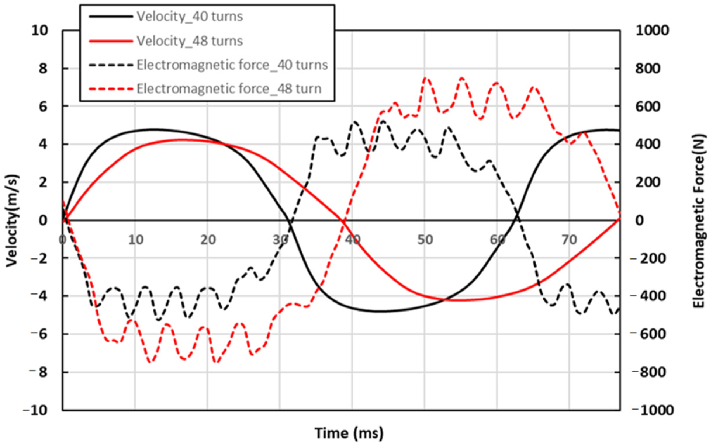
As a crucial force influencing LJEG dynamics, the alternator’s electromagnetic force is vital in ensuring LJEG stability and optimal performance. Figure 5 presents the FEA simulation results of electromagnetic force versus the translator velocity. Two moving magnet tubular alternators with 40 and 48 coil turns are employed. The alternator, with 48 turns, delivers a larger electromagnetic force at the same translator velocity. The non-linear relationship between electromagnetic force and translator velocity is observed, which will not reflect in a simplified ideal damper model. The comparison of transient profiles of electromagnetic force and translator velocity during LJEG operation is demonstrated in Figure 6. As observed, the electromagnetic force has a fluctuating and flatter shape with a change in velocity. The fluctuation arises from the combined influence of cogging and armature reaction forces. The flattened profile at the peak results from the inductance effect [29]. When the 48-turn alternator is simulated, electromagnetic force increases and peak velocity is reduced. Moreover, as shown in Figure 7, engine power output and thermal efficiency increased. The alternator with 48-turn is adopted for subsequent investigation, as a further increase in electromagnetic force will lead to a drop in piston velocity and unstable engine running.
5.2. Target Stroke
The operating parameters of the LJEG with various target strokes are presented in Figure 8. The heat input is maintained at 5.5 kW, and the expander exhaust valve is closed at 11 mm. The peak velocity increased with piston strokes, as shown in Figure 8a, while the frequency is nearly constant, around 13 Hz for the investigated cases. Figure 8b presents the in-cylinder pressure profiles of the left-hand-side expander and right-hand-side compressor. The relatively flat stage in the early phase of the expansion process corresponds to the expander intake valve’s opening window. During this phase, the high-energy working fluid flows into the expander to drive the piston with a moderate decrease in pressure. A greater quantity of working fluid is allowed into the cylinder at a longer intake duration, which results in extended piston strokes. Moreover, as the piston strokes increase, higher pressure levels and sufficient expansion processes are found after the intake valve is closed, which helps convert more energy of working fluid into mechanical power. On the compressor side, the in-cylinder pressure and the position where the exhaust valve opens (indicated by the first turning point from left to right of Figure 8b) are almost unchanged despite the increase in compression strokes with extended strokes.
With a longer stroke, more power is extracted from the working fluid in the expander. It can be observed that pressure drops more rapidly at the beginning of the compressor intake process as a stroke increases. The compressor intake valve opens when in-cylinder pressure drops below ambient pressure; however, a more rapid drop of in-cylinder pressure leads to an earlier start of the intake process and a greater amount of working fluid introduced. As a result, around a 2% increase in engine thermal efficiency (ηt) and the thermal to electric energy conversion efficiency (ηte) is achieved as strokes increase from 108 mm to 116 mm. The same heat input enhances mechanical (Pm) and electric (Pe) power output. Although the simulation results suggest further performance improvement is possible by achieving longer strokes, accurate control of piston motion around the dead centre is more challenging. Therefore, the target-operating stroke is set at 116 mm for subsequent investigations.
5.3. Exhaust Valve Closing Timing
The expander exhaust valve close position (EVC) is another parameter that controls the LJEG. Operating parameters of the LJEG with various EVC positions are evaluated, while the stroke and heat input are kept at 116 mm and 5.5 kW, respectively. As indicated in Figure 9a, the change in EVC positions shows a minor influence on piston motion. However, in Figure 9b, an apparent drop in peak pressure of both the expander and compressor is observed, as EVC is advanced despite increased pressure within the expander at the conclusion of the exhaust phase. The influence of EVC on efficiency and power output is less straightforward in Figure 9c,d. With advanced EVC, efficiency and power firstly increased and then dropped. The close coupling between the expander and compressor of the LJEG system can explain this. Earlier EVC will cause less energy to be delivered to the compressor, as indicated by the reduced pressure observed at the conclusion of the compression process, as illustrated in Figure 9b. This trend will influence engine efficiency in two opposite directions: the compressor consumes less energy, while more power output is expected; however, the decrease in the pressure of the working fluid that drives the expander also reduces the mechanical power delivered. The trade-off between these two aspects leads to the trend observed in efficiency and power output. After reaching the peak efficiency and power output at an EVC of 14 mm, further investigation is conducted using this adopted EVC.
5.4. Heat Addition
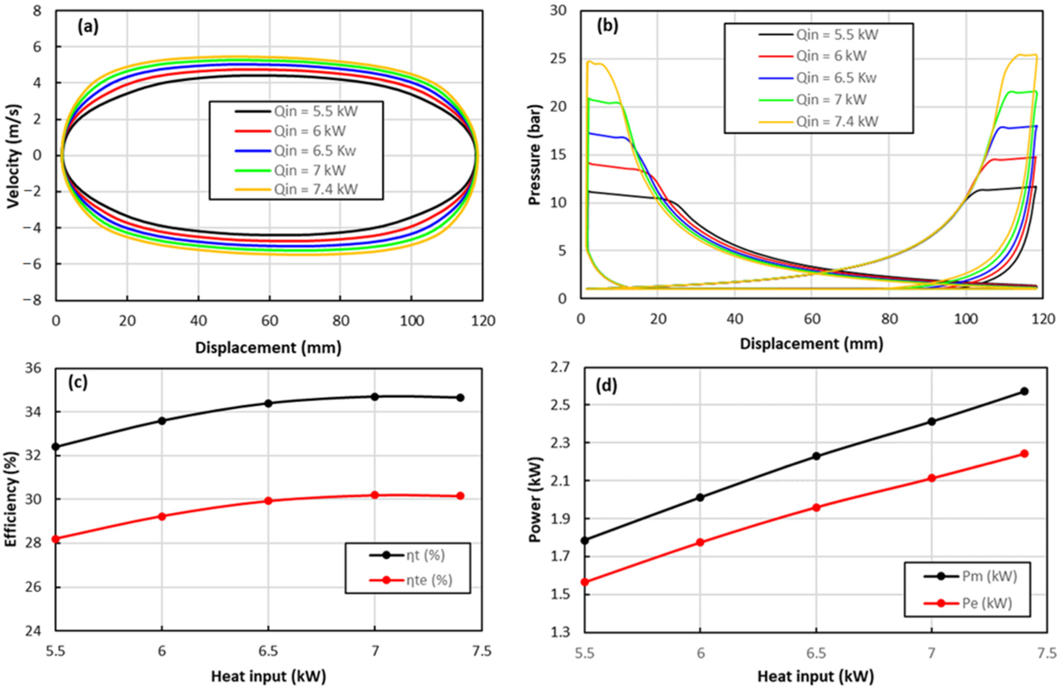
The influence of heat input (Qin) on the LJEG operating parameters is demonstrated in Figure 10. With more heat input, the piston peak velocity increased. Moreover, the velocity profile flattens in the middle of the stroke (Figure 10a). The in-cylinder pressure profiles presented in Figure 10b indicate the reason behind this trend in velocity. As heat input increases, the expander and compressor’s peak pressure rises. As the stroke is unchanged, the expander intake valve’s opening window must be narrowed to restrict the working fluid from entering the expander to drive the piston forward. As a result, the driving gas force at the beginning of the expansion stroke has a larger amplitude but shorter duration, which leads to a more significant acceleration within this brief period. As the pressure between the expander and compressor increases, the compressor’s intake valve opens later, as the compressor’s air needs to be further compressed to overcome the valve’s cracking pressure. As shown in Figure 10c,d, efficiency and power output increase steadily with a higher heat input. However, the efficiency increase gradually becomes smaller, implying that a limitation exists for heat input addition. Figure 10b highlights that the opening window of the expander intake valve should be shortened to regulate piston motion effectively. Nevertheless, if the heat input exceeds a specific threshold (7.4 kW, as indicated in Figure 10), the simulation suggests that the piston might collide with the cylinder head. However, practical application poses challenges in actuating the valve beyond 6.5 kW heat input due to constraints such as limited valve opening and closing time and the force required for valve system actuation. Furthermore, the metallurgical limitations of engine components would restrict increased heat input.
Consequently, a heat input of 6.5 kW is chosen as the optimised value, resulting in mechanical and electric power outputs of 2.23 kW and 1.96 kW, respectively. The thermal efficiency of this configuration is 34.3%, accompanied by an electric energy efficiency of 30%.
5.5. Summary
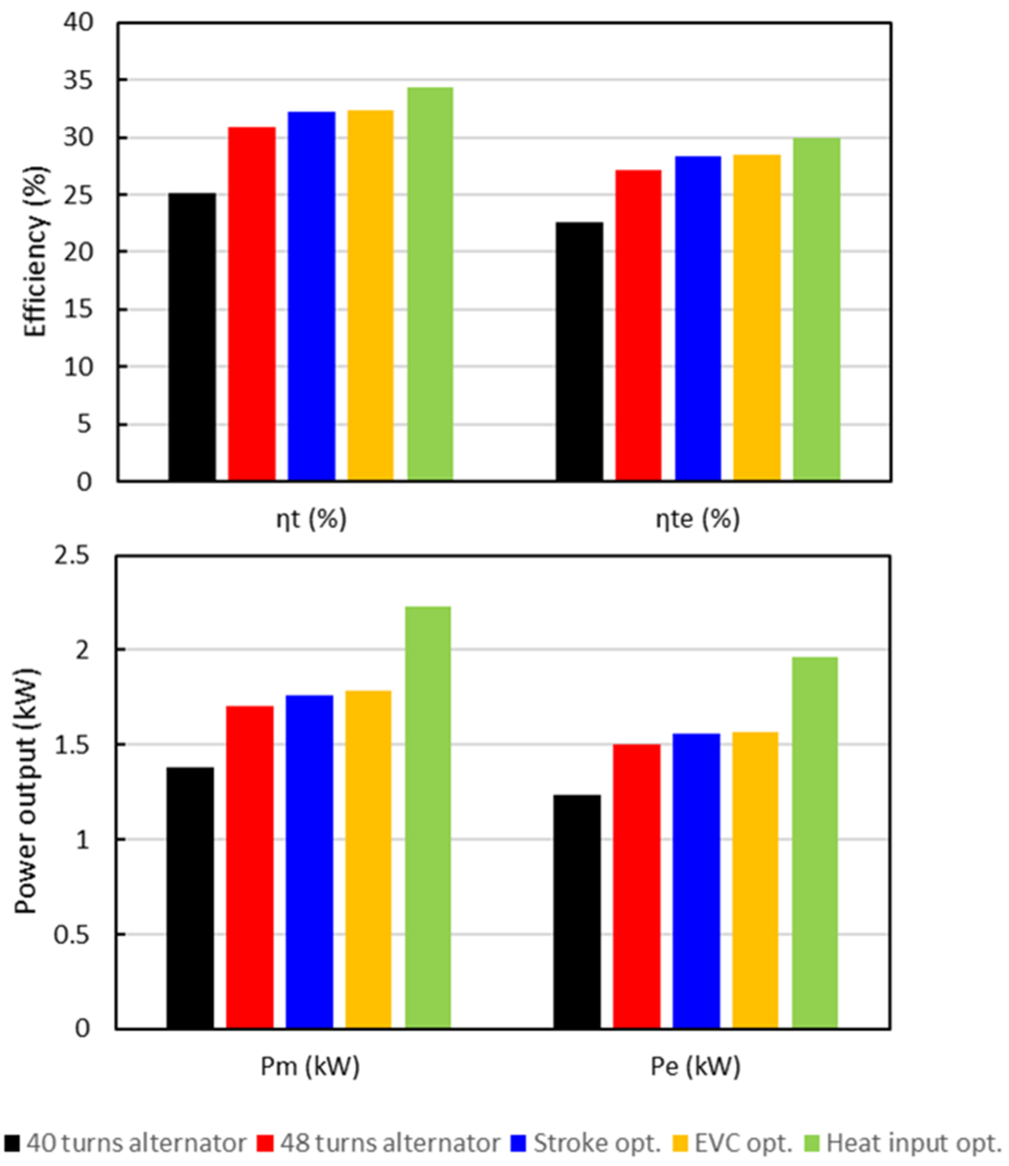
The performance optimisation process conducted above is summarised in Figure 11, demonstrating each parameter’s contribution. The critical importance of matching the engine and alternator is obvious and deserves further investigation. Regarding the control parameters, heat input directly influences efficiency and power output, followed by operating stroke, while minor effects are found in regard to the exhaust valve’s closed position. Therefore, the control of the combustor unit and expander intake valve are identified as the critical control parameters for achieving high efficiency and power output from the LJEG system.
5.6. Further Discussions on Ammonia Combustion and Emissions
Because of the external combustion characteristics of the LJEG, it is possible to optimise ammonia combustion independently to reduce NOx emission while delivering the required heat, which is the critical concern in using ammonia as fuel. This section investigates the effects of equivalence ratio, hydrogen addition, oxygen enrichment and pressure on NO formation, as well as reduction during the ammonia combustion process.
It has been identified that the LJEG requires 6.5 kW of heat input to achieve optimum performance. The combustion analysis is carried out on a constant heat release rate basis. The heat release rate with different reactant compositions and pressures is calculated at various reactant mass flow rates. As shown in Figure 12, the heat release rate increases linearly with the mass flow rate for various fuel/air mixtures. The influence of reactant composition on combustion kinetics can be observed at various mass flow rates. As the reactant changes from lean to rich fuel, the heat release rate rises, peaks at an equivalence ratio between 1.0 and 1.1, and then falls slightly as the fuel/air mixture becomes rich. This trend is consistent with the findings in ammonia/air premixed flame speed [33]. While adding hydrogen or oxygen leads to an apparent enhancement of heat release rate, negligible influence is found from pressure. Based on those findings, the mass flow rates of reactants with various compositions and pressure are adjusted to maintain the heat release rate from combustion at 6.5 kW, used as the input in the following parametric analysis.
Since nitric oxide (NO) is the predominant NOx species in ammonia combustion, as opposed to NO2 and N2O [18], only the results related to NO are presented. The results of the NO mole fraction in the combustion product are summarised in Figure 13. Considering the variation in initial ammonia (NH3) mole fraction in reactants with different compositions, which is expected to affect nitrogen-related species concentration, the NO mole fraction normalised against the initial NH3 mole fraction is presented, while the influence of the equivalence ratio is illustrated in Figure 13a. It is found that the NO mole fraction peaks at the equivalence ratio of 0.9 and decreases dramatically as the ratio further increases. A similar trend was also observed in ammonia/methane/air-premixed flame [34]. Considering that ammonia’s maximum burning velocity is achieved with an equivalence ratio of 1.0~1.1, maintaining an equivalence ratio of 1.1 in ammonia/air premixed combustion proves advantageous for ensuring combustion stability and minimising NO emissions. The normalised NO mole fraction trend is similar, although the peak at an equivalence ratio of 0.9 diminishes. The equivalence ratio is set as 1.1 in further investigation of hydrogen/oxygen addition and pressure variation. While adding hydrogen or oxygen is an effective method to enhance ammonia combustion, they cause an apparent increase in NO emission, as shown in Figure 13b,c. At 30% volume hydrogen blend, NO mole fraction in combustion product is more than doubled compared with pure ammonia combustion. The influence of oxygen enrichment is more intense, as the NO mole fraction is more than ten times higher when the air’s volumetric fraction increases from 21% to 30%. Interesting characteristics are observed in the effects of pressure on NO emission. As pressure is elevated, a significant reduction in the NO mole fraction is found, although the effects become weaker as pressure increases. Therefore, it is possible to simultaneously achieve combustion and low NO emission with the appropriate selection of reactant composition and pressure. To scrutinise the mechanisms underlying pressure and NO formation, the impacts of reactant composition and pressure on NO’s formation and reduction pathways are further examined, aided by the analysis of the Rate of Production (ROP).
For a fuel without nitrogen, the dominant route of NO production during its combustion in air is the extended Zeldovich mechanism, also referred to as the thermal-NO mechanism [35]. Three significant reactions are involved in this mechanism: N2 + O = NO + N, N + O2 = NO + O and N + OH = NO + H. However, in ammonia combustion, the fuel-bond-NO mechanism plays a vital role in NO production and reduction [18]. The reaction pathway proposed by Miller et al. [36] is widely accepted. Ammonia combustion starts with H-abstraction by OH/H/O radicals, forming the NH2 radical. Subsequently, the NH2 radical can proceed through three channels: reacting with O radicals to yield HNO, engaging with primary intermediates leading to NO formation, and undergoing further H-abstraction by H/OH radicals to form the NH radical, which subsequently reacts with NO, and contributing to NO reduction.
Similar pathways apply to the NH radical: converted into NO directly or via HNO, or further H-abstraction to produce the N atom, which, in turn, is oxidised into NO or reacts with NO to produce N2. Several reaction channels exist for each step, and the contribution from each channel is closely relevant to the abundance of certain radicals, which is influenced by the composition of the reactant in terms of equivalence ratio and additive blending ratio. Pressure can also exert its influence either directly through pressure-dependence reactions or by affecting the radical pools.
Figure 14 presents the ROP analysis results, focusing on monotonic trends from Figure 13. For conciseness, only two result sets per case are discussed. Examining various parameters highlights the equivalence ratio’s pivotal role in altering the relative contribution of critical reactions for NO formation and reduction. In lean combustion, the primary NO production pathway involves the HNO intermediate. Conversely, rich combustion exhibits nitrogen atom oxidation as the predominant ROP reaction (Figure 14a). This difference in radical pools between lean and rich combustion explains the observed variations in NO-related processes. In lean combustion, abundant O/H radicals facilitate the conversion of NH2/NH radicals to NO primarily via HNO. As the equivalence ratio increases, O/H radical concentration decreases, but in richer combustion, the proportion of H radicals in O/H radical pools rises. This favours the H-abstraction of NH2/NH radicals over their conversion to NO. Consequently, NO formation primarily occurs through nitrogen atom oxidation, the ultimate H-abstraction product of NH2/NH radicals.
Furthermore, due to the absence of O radicals, NH2/NH radicals are prone to react with NO, affecting the apparent lower NO mole fraction in rich combustion products. Despite maintaining the equivalence ratio at 1.2 in the parametric analysis of other factors, the relative importance of each reaction for NO production and reduction remains unchanged. Nonetheless, the absolute ROP of the dominant reaction governing NO formation and reduction is influenced, thereby contributing to the observed trends in the NO mole fraction, as depicted in Figure 13.
Introducing hydrogen to ammonia enhances N-atom-related reactions, resulting in an about 45% increase in NO production with a 30% hydrogen addition, as illustrated in Figure 14b. This is attributed to the augmented H atom in the radical pool favouring H-abstraction from NHi species and suppressing their reaction with NO. Oxygen enrichment of 40% further amplifies NO production through the N-atom by 139% and HNO intermediate pathways by over 10%, as shown in Figure 14c. This phenomenon, observed by Li et al. [37], in oxygen-enriched ammonia/air-premixed flames is characterised by a steady rise in O, OH, and N radical concentrations, with increasing oxygen promoting N-related and HNO-related reactions. The reduction in NO emission at elevated pressure is attributed to the depletion of the O/H radical pool, resulting from pressure-sensitive three-body reactions (H + OH + M = H2O + M and H + O2 + M = HO2 + M) [18].
6. Conclusions
The concept of a Linear Joule Cycle Engine Generator (LJEG) featuring external ammonia combustion for power generation is presented in this study. A comprehensive dynamic model for the LJEG is coupled that integrates thermodynamics, electromagnetics, mechanics, and combustion chemistry. Validation against test data from a linear engine prototype ensures the model’s accuracy. Subsequently, the model is employed to optimise the LJEG system’s performance.
In addressing the issue of NO emissions from ammonia combustion, a chemical kinetic analysis is conducted to investigate various parameters influencing NO formation and reduction during LJEG working conditions. The key findings are summarised as follows:
- A significant influence on the power output and efficiency of the LJEG system is found in the electromagnetic force characteristics of the alternator, which highlights the importance of an appropriate matching between the alternator and engine unit. A more comprehensive alternator model, surpassing the simplified ideal damper assumption, is recommended for a more accurate prediction of LJEG behaviour.
- Investigation of the primary control parameters on LJEG performance indicated that efficiency and power output are improved by increasing heat input or extending the operating stroke. Simultaneously, a minor improvement can also be accomplished by optimising the expander exhaust valve close position. Because of the optimisation, a 6.5 kW of heat input resulted in 2.23 kW and 1.96 kW of mechanical and electric power output, respectively, with a thermal efficiency of 34.3% and electric energy conversion efficiency of 30%.
- The effects of equivalence ratio, hydrogen addition, oxygen enrichment and pressure on NO formation and reduction in ammonia combustion are investigated, with the heat release rate kept constant at the amount required by the LJEG. Rich combustion and elevated pressure are found to be beneficial for NO reduction. The findings indicate that maintaining an equivalence ratio of 1.2 yields emissions lower than 0.8. Additionally, conducting combustion at an elevated pressure of five bar is favourable for reducing emissions compared to operating at one bar. Although blending hydrogen with ammonia contributes to stable combustion, it can increase emissions. Appropriate reactant composition and pressure selection are essential to achieving robust combustion and low NO emission simultaneously.
- The results of the rate of NO production analysis conducted indicated that only the equivalence ratio could significantly change the relative contribution among the critical reactions for NO formation and reduction. NO is primarily produced via the HNO intermediate in lean combustion, while the pathway through N atom oxidation dominates in rich combustion. With minor influence on the reaction pathway, hydrogen/oxygen addition and pressure elevation lead to a change in O/H radical pools and alter NO emission in turn.
Author Contributions
Conceptualization, G.C. and D.W.; methodology, U.N. and G.C.; software, G.C.; validation, G.C. and U.N.; formal analysis, D.W. and M.L.; investigation, G.C. and U.N.; resources, D.W.; data curation, M.L. and G.C.; writing—original draft preparation, G.C. and U.N.; writing—review and editing, U.N. and D.W.; supervision, D.W.; funding acquisition, D.W. All authors have read and agreed to the published version of the manuscript.
Funding
This research was support from EPSRC (Engineering and Physical Sciences Research Council, United Kingdom) on the project—Powering Carbon-free Autonomous Shipping: Ammonia/Hydrogen dual-fuelled Linear Engine-Generator (EP/S00193X/2) and the UK National Clean Maritime Research Hub (EP/Y024605/1).
Data Availability Statement
The data presented in this study are available on request from the corresponding author.
Conflicts of Interest
The authors declare no conflicts of interest.
Nomenclature
| a (m/s2) | acceleration |
| Aht (mm2) | characteristic heat transfer area |
| Cs (-) | Stribeck constant |
| d (mm) | wall thickness |
| D (mm) | cylinder bore diameter |
| hi (J/kg) | specific enthalpy |
| h (W/m2∙K) | convective heat transfer coefficient |
| k (W/m∙K) | thermal conductivity |
| Fg (N) | gas force |
| Fa (N) | alternator electromagnetic force |
| Ff (N) | friction force |
| Ffd (N) | dry friction force |
| Ffp (N) | pressure friction force |
| Ffc (N) | Coulomb friction force |
| Ffs (N) | static friction force |
| Fla (N) | linear generator responding force |
| Fele (N) | electrical force |
| Fcog (N) | cogging force |
| Fco (N) | core loss force |
| Fed (N) | eddy current force |
| Fcp (N) | copper loss force |
| Far (N) | armature reaction force |
| m (kg) | moving mass |
| Q (J) | heat transfer |
| Qin (J) | heat input |
| (kg/s) | mass flow rate |
| Nu (-) | Nusselt number |
| Re (-) | Reynolds number |
| V (mm3) | in-cylinder volume |
| W (mm) | piston ring width |
| (-) | specific heat ratio |
| (W/m2∙K) | overall heat transfer coefficient |
| ηt (%) | engine thermal efficiency |
| ηte (%) | thermal to electric energy conversion efficiency |
| (-) | pressure friction coefficient |
| φ (-) | fuel-air equivalence ratio |
References
- Solouk, A.; Shakiba-Herfeh, M.; Arora, J.; Shahbakhti, M. Fuel consumption assessment of an electrified powertrain with a multi-mode high-efficiency engine in various levels of hybridization. Energy Convers. Manag. 2018, 155, 100–115. [Google Scholar] [CrossRef]
- Jia, B.; Wu, D.; Smallbone, A.; Ngwaka, U.C.; Roskilly, A.P. Dynamic and thermodynamic characteristics of a linear Joule engine generator with different operating conditions. Energy Convers. Manag. 2018, 173, 375–382. [Google Scholar] [CrossRef]
- Hung, N.B.; Lim, O. A review of free-piston linear engines. Appl. Energy 2016, 178, 78–97. [Google Scholar] [CrossRef]
- Guo, C.; Zuo, Z.; Feng, H.; Jia, B.; Roskilly, T. Review of recent advances of free-piston internal combustion engine linear generator. Appl. Energy 2020, 269, 115084. [Google Scholar] [CrossRef]
- Kosaka, H.; Akita, T.; Moriya, K.; Goto, S.; Hotta, Y.; Umeno, T.; Nakakita, K. Development of Free Piston Engine Linear Generator System Part 1—Investigation of Fundamental Characteristics; SAE Technical Paper Series; SAE International400 Commonwealth Drive: Warrendale, PA, USA, 2014. [Google Scholar] [CrossRef]
- Li, L.; Luan, Y.; Wang, Z.; Deng, J.; Wu, Z. Simulations of Key Design Parameters and Performance Optimization for a Free-Piston Engine; SAE Technical Paper Series; SAE International400 Commonwealth Drive: Warrendale, PA, USA, 2010. [Google Scholar] [CrossRef]
- Huang, L. An Opposed-Piston Free-Piston Linear Generator Development for HEV; SAE Technical Paper Series; SAE International400 Commonwealth Drive: Warrendale, PA, USA, 2012. [Google Scholar] [CrossRef]
- Zhang, Z.; Feng, H.; Jia, B.; Zuo, Z.; Smallbone, A.; Roskilly, A.P. Effect of the stroke-to-bore ratio on the performance of a dual-piston free piston engine generator. Appl. Therm. Eng. 2021, 185, 116456. [Google Scholar] [CrossRef]
- Feng, H.; Zhang, Z.; Jia, B.; Zuo, Z.; Smallbone, A.; Roskilly, A.P. Investigation of the optimum operating condition of a dual piston type free piston engine generator during engine cold start-up process. Appl. Therm. Eng. 2020, 182, 116124. [Google Scholar] [CrossRef]
- Johnson, T.A.; Leick, M.T.; Moses, R.W. Experimental Evaluation of a Prototype Free Piston Engine—Linear Alternator (FPLA) System; SAE Technical Paper Series; SAE International400 Commonwealth Drive: Warrendale, PA, USA, 2016. [Google Scholar] [CrossRef]
- Mikalsen, R.; Roskilly, A.P. The Free-Piston Reciprocating Joule Cycle Engine: A New Approach To Efficient Domestic CHP Generation. In Proceedings of the International Conference on Applied Energy 2012 Conference, Suzhou, China, 5–8 July 2012. [Google Scholar]
- Han, Y.; Kang, J.; Zhang, G.; Liu, Z.; Tian, J.; Chai, J. Performance evaluation of free piston compressor coupling organic Rankine cycle under different operating conditions. Energy Convers. Manag. 2014, 86, 340–348. [Google Scholar] [CrossRef]
- Han, Y.; Kang, J.; Wang, X.; Liu, Z.; Tian, J.; Wang, Y. Modelling and simulation analysis of an ORC-FPC waste heat recovery system for the stationary CNG-fuelled compressor. Appl. Therm. Eng. 2015, 87, 481–490. [Google Scholar] [CrossRef]
- Ngangué, M.N.; Stouffs, P. Dynamic simulation of an original Joule cycle liquid pistons hot air Ericsson engine. Energy 2019, 190, 116293. [Google Scholar] [CrossRef]
- Ngwaka, U.; Wu, D.; Happian-Smith, J.; Jia, B.; Smallbone, A.; Diyoke, C.; Roskilly, A.P. Parametric Analysis of a Semi-Closed-Loop Linear Joule Engine Generator using Argon and Oxy-Hydrogen Combustion. Energy 2021, 217, 119357. [Google Scholar] [CrossRef]
- Li, M.; Ngwaka, U.; Korbekandi, R.M.; Baker, N.; Wu, D.; Tsolakis, A. A closed-loop linear engine generator using inert gases: A performance and exergy study. Energy 2023, 281, 128278. [Google Scholar] [CrossRef]
- Verhelst, S.; Wallner, T. Hydrogen-fueled internal combustion engines. Prog. Energy Combust. Sci. 2009, 35, 490–527. [Google Scholar] [CrossRef]
- Kobayashi, H.; Hayakawa, A.; Somarathne, K.K.A.; Okafor, E.C. Science and technology of ammonia combustion. Proc. Combust. Inst. 2019, 37, 109–133. [Google Scholar] [CrossRef]
- Kojima, Y.; Miyaoka, H.; Ichikawa, T. Ammonia-Based Hydrogen Storage Materials. In Advanced Materials for Clean Energy; CRC Press: Boca Raton, FL, USA, 2015; pp. 512–541. [Google Scholar]
- Mathieu, O.; Petersen, E.L. Experimental and modeling study on the high-temperature oxidation of Ammonia and related NOx chemistry. Combust. Flame 2015, 162, 554–570. [Google Scholar] [CrossRef]
- Hayakawa, A.; Arakawa, Y.; Mimoto, R.; Somarathne, K.K.A.; Kudo, T.; Kobayashi, H. Experimental investigation of stabilization and emission characteristics of ammonia/air premixed flames in a swirl combustor. Int. J. Hydrogen Energy 2017, 42, 14010–14018. [Google Scholar] [CrossRef]
- Okafor, E.C.; Naito, Y.; Colson, S.; Ichikawa, A.; Kudo, T.; Hayakawa, A.; Kobayashi, H. Measurement and modelling of the laminar burning velocity of methane-ammonia-air flames at high pressures using a reduced reaction mechanism. Combust. Flame 2019, 204, 162–175. [Google Scholar] [CrossRef]
- Takeishi, H.; Hayashi, J.; Kono, S.; Arita, W.; Iino, K.; Akamatsu, F. Characteristics of ammonia/N2/O2 laminar flame in oxygen-enriched air condition. Trans. JSME 2015, 81, 14–00423. [Google Scholar] [CrossRef]
- Frigo, S.; Gentili, R. Analysis of the behaviour of a 4-stroke Si engine fuelled with ammonia and hydrogen. Int. J. Hydrogen Energy 2013, 38, 1607–1615. [Google Scholar] [CrossRef]
- Ryu, K.; Zacharakis-Jutz, G.E.; Kong, S.-C. Performance characteristics of compression-ignition engine using high concentration of ammonia mixed with dimethyl ether. Appl. Energy 2014, 113, 488–499. [Google Scholar] [CrossRef]
- Heywood, J.B. Internal Combustion Engine Fundamentals; McGraw-Hill: New York, NY, USA, 1988. [Google Scholar]
- Nakamura, H.; Hasegawa, S.; Tezuka, T. Kinetic modeling of ammonia/air weak flames in a micro flow reactor with a controlled temperature profile. Combust. Flame 2017, 185, 16–27. [Google Scholar] [CrossRef]
- Otomo, J.; Koshi, M.; Mitsumori, T.; Iwasaki, H.; Yamada, K. Chemical kinetic modeling of ammonia oxidation with improved reaction mechanism for ammonia/air and ammonia/hydrogen/air combustion. Int. J. Hydrogen Energy 2018, 43, 3004–3014. [Google Scholar] [CrossRef]
- Jalal, A.S.; Baker, N.J.; Wu, D. Electrical Machine Design for use in an External Combustion Free Piston Engine. In Proceedings of the 5th IET International Conference on Renewable Power Generation (RPG) 2016, London, UK, 22 September 2016. [Google Scholar] [CrossRef]
- Ngwaka, U.; Jia, B.; Lawrence, C.; Wu, D.; Smallbone, A.; Roskilly, A.P. The characteristics of a Linear Joule Engine Generator operating on a dry friction principle. Appl. Energy 2019, 237, 49–59. [Google Scholar] [CrossRef]
- Pennestrì, E.; Rossi, V.; Salvini, P.; Valentini, P.P. Review and comparison of dry friction force models. Nonlinear Dyn. 2015, 83, 1785–1801. [Google Scholar] [CrossRef]
- Yuan, C.; Xu, J.; He, Y. Parametric study on the starting of a free-piston engine alternator. Int. J. Engine Res. 2017, 19, 411–422. [Google Scholar] [CrossRef]
- Mei, B.; Zhang, X.; Ma, S.; Cui, M.; Guo, H.; Cao, Z.; Li, Y. Experimental and kinetic modeling investigation on the laminar flame propagation of ammonia under oxygen enrichment and elevated pressure conditions. Combust. Flame 2019, 210, 236–246. [Google Scholar] [CrossRef]
- Xiao, H.; Valera-Medina, A.; Bowen, P.J. Study on premixed combustion characteristics of co-firing ammonia/methane fuels. Energy 2017, 140, 125–135. [Google Scholar] [CrossRef]
- Khalil, A.T.; Manias, D.M.; Kyritsis, D.C.; Goussis, D.A. NO formation and autoignition dynamics during combustion of H2O-diluted NH3/H2O2 mixtures with air. Energies 2020, 14, 84. [Google Scholar] [CrossRef]
- Miller, J.A.; Smooke, M.D.; Green, R.M.; Kee, R.J. Kinetic Modeling of the Oxidation of Ammonia in Flames. Combust. Sci. Technol. 1983, 34, 149–176. [Google Scholar] [CrossRef]
- Li, J.; Huang, H.; Kobayashi, N.; He, Z.; Osaka, Y.; Zeng, T. Numerical study on effect of oxygen content in combustion air on ammonia combustion. Energy 2015, 93, 2053–2068. [Google Scholar] [CrossRef]
Figure 1.
Schematic diagram of the LJEG.

Figure 2.
Configuration of the coupled LJEG model.

Figure 3.
Experimental and simulation results of linear engine prototype: (a) displacement; (b) velocity; (c) acceleration [30].
Figure 3.
Experimental and simulation results of linear engine prototype: (a) displacement; (b) velocity; (c) acceleration [30].

Figure 4.
Comparison of test data and simulation results of: (a) no-load back EMF; (b) cogging force; (c) static force.
Figure 4.
Comparison of test data and simulation results of: (a) no-load back EMF; (b) cogging force; (c) static force.

Figure 5.
Electromagnetic force versus the translator velocity of two linear alternators with different turns of coil.
Figure 5.
Electromagnetic force versus the translator velocity of two linear alternators with different turns of coil.

Figure 6.
Electromagnetic force and velocity of LJEG with two linear alternators.

Figure 7.
Engine mechanical power output and thermal efficiency with two linear alternators.

Figure 8.
Parameters of LJEG with various operating stroke: (a) velocity; (b) in-cylinder pressure; (c) efficiency; (d) power output.
Figure 8.
Parameters of LJEG with various operating stroke: (a) velocity; (b) in-cylinder pressure; (c) efficiency; (d) power output.

Figure 9.
Parameters of LJEG with various expander exhaust valve close position (EVC): (a) velocity; (b) in-cylinder pressure; (c) efficiency; (d) power output.
Figure 9.
Parameters of LJEG with various expander exhaust valve close position (EVC): (a) velocity; (b) in-cylinder pressure; (c) efficiency; (d) power output.

Figure 10.
Parameters of LJEG with various heat input: (a) velocity; (b) in-cylinder pressure; (c) efficiency; (d) power output.
Figure 10.
Parameters of LJEG with various heat input: (a) velocity; (b) in-cylinder pressure; (c) efficiency; (d) power output.

Figure 11.
Summary of LJEG performance optimisation process.

Figure 12.
Heat release rates with various reactant composition and pressure: (a) with fuel/air equivalence ratio from 0.8 to 1.2 (ammonia/air, 1 bar); (b) with hydrogen volumetric ratio in fuel from 0 to 30% (ammonia/hydrogen/air, 1 bar); (c) with oxygen volumetric ratio in air from 21 to 40% (ammonia/oxygen enriched air, 1 bar); (d) with pressure from 1 bar to 5 bar (ammonia/air, equivalence ratio = 1).

Figure 13.
Summary of NO mole fraction in combustion products, both before and after normalisation against the initial NH3 mole fraction, with consideration of various parameters, including (a) equivalence ratio, (b) hydrogen volumetric ratio in the fuel, (c) oxygen volumetric ratio in the air; and (d) pressure.

Figure 14.
Rate of production for NO with various (a) equivalence ratio; (b) hydrogen volumetric ratio in fuel; (c) oxygen volumetric ratio in air; (d) pressure.
Figure 14.
Rate of production for NO with various (a) equivalence ratio; (b) hydrogen volumetric ratio in fuel; (c) oxygen volumetric ratio in air; (d) pressure.


Table 1.
Dimensions of the LJEG prototype.
| Components | Parameter [Unit] | Value |
|---|---|---|
| Engine | Expander bore [mm] | 80 |
| Compressor bore [mm] | 70 | |
| Stroke [mm] | 120 | |
| Linear alternator | Outer diameter of the strator [mm] | 180 |
| Outer diameter of the translator [mm] | 103 | |
| Active electromagnetic length [mm] | 120 | |
| Air gap [mm] | 1.5 |
Table 2.
Friction model parameters.
| Parameters [Unit] | Values |
|---|---|
| Normal force (Fn) [N] | 89.1 |
| Static friction coefficient | 0.107 |
| Dynamic friction coefficient | 0.102 |
| Stribeck constant (Cs) [m/s] | 0.001 |
| Pressure friction coefficient | 0.3 |
Disclaimer/Publisher’s Note: The statements, opinions and data contained in all publications are solely those of the individual author(s) and contributor(s) and not of MDPI and/or the editor(s). MDPI and/or the editor(s) disclaim responsibility for any injury to people or property resulting from any ideas, methods, instructions or products referred to in the content. |
© 2024 by the authors. Licensee MDPI, Basel, Switzerland. This article is an open access article distributed under the terms and conditions of the Creative Commons Attribution (CC BY) license (https://creativecommons.org/licenses/by/4.0/).
Share and Cite
MDPI and ACS Style
Chen, G.; Ngwaka, U.; Wu, D.; Li, M. Performance and Emission Optimisation of an Ammonia/Hydrogen Fuelled Linear Joule Engine Generator. Energies 2024, 17, 1490. https://doi.org/10.3390/en17061490
AMA Style
Chen G, Ngwaka U, Wu D, Li M. Performance and Emission Optimisation of an Ammonia/Hydrogen Fuelled Linear Joule Engine Generator. Energies. 2024; 17(6):1490. https://doi.org/10.3390/en17061490
Chicago/Turabian StyleChen, Gen, Ugochukwu Ngwaka, Dawei Wu, and Mingqiang Li. 2024. "Performance and Emission Optimisation of an Ammonia/Hydrogen Fuelled Linear Joule Engine Generator" Energies 17, no. 6: 1490. https://doi.org/10.3390/en17061490
Note that from the first issue of 2016, this journal uses article numbers instead of page numbers. See further details here.