


A New Study on the Effect of the Partial Wake Generated in a Wind Farm
Mechanical Engineering Department, University of M’sila, M’sila 28000, Algeria
*
Author to whom correspondence should be addressed.
Energies 2024, 17(6), 1498; https://doi.org/10.3390/en17061498
Submission received: 11 January 2024
/
Revised: 15 March 2024
/
Accepted: 19 March 2024
/
Published: 21 March 2024
Abstract
:In this article, we present an investigative study on the often-overlooked partial wake phenomenon in previous studies concerning wind farm configurations. A partial wake occurs when a portion of the actuator disk of a downstream wind turbine is affected by the wake of another upstream turbine. This phenomenon occurs in addition to the full wake, where the entire upstream turbine is affected by the wake of the frontal turbine, also leading to a decrease in wind speed and consequently a reduction in power production. The proposed study is based on measuring the power generated by the area swept by the wake of an array of turbines in a wind farm. To accomplish this, we integrate the linear wake model of Jensen, the specifications of the ENERCON E2 wind turbine, and the wind farm data into Matlab-developed software (version 18) to perform the calculations. In a concrete application, this proposed method is validated by reproducing the previous works that neglected the partial wake in wind farm configurations. The simulation results obtained are analyzed, compared, and discussed under similar operational conditions.
1. Introduction
Wind energy is a renewable and sustainable energy source that relies on the inexhaustible power of the wind. As wind forces act on the blades, they induce rotor rotation, which turns the generator, converting the wind’s energy into electricity. This generated electric current can be either integrated into existing electrical grids or used directly in isolated places. Due to these advantages, the portion of wind energy to global electricity production continues to increase, facilitating the installation of large-scale wind turbines in both offshore and onshore wind farms across the world [1]. However, the efficiency of wind farms heavily relies on how the wind turbines are arranged, particularly in downstream positions, where they are affected by the wake of the frontal wind turbines. The wake phenomenon, associated with dense groupings of wind turbines in wind farms, leads to a speed deficit, affecting the performance of the turbines and reducing energy production [2].
As a wind turbine can only transform a portion of the available wind energy from wind into clean electricity, another wind turbine totally or partially immersed in the wake receives less energy. This phenomenon is called the wake effect [3,4]. In wind farm configurations, the wake effect has been the subject of several studies carried out by researchers employing different models and analytical methods to describe the evolution of wind speed and model the wakes generated within wind farms. The first works in this field were presented by Betz [5,6] and Lanchester [7] in the early 1920s. Their work aimed at optimizing wind turbine performance and understanding downstream wind speed, forming the basis for future research on the characteristics of the wake zone. With advancements in computer technology, it has been observed that a number of wake models have been developed, including empirical-analytical models and computational fluid dynamics (CFD) models [8,9]. Empirical-analytical models, notable for their simplicity and computational speed, are often referred to as explicit models [10,11,12,13], as highlighted by Barthelmie [14] and Ishihara [15]. Other CFD models classified as implicit models [16,17], such as those presented by Crasto et al. [18] and Crespo [19], generally involve more complex mathematical tools and consume significant computational resources due to the lack of flexibility in application to different problems [20]. Consequently, the majority of commercial software for optimizing the positions of wind turbines in wind farms uses simpler empirical-analytical models.
Although other analytical models exist that take into account three-dimensional wakes and vertical wind shear, such as the one presented by Zhao [21], the linear model by Jensen [22], which focuses on two-dimensional wakes, is widely adopted in optimization methods. This empirical-analytical model is also widely used to estimate the wind speed within the wake [23]. Due to its speed and ease of programming, it is particularly suitable for wind farm layout systems, both onshore and offshore, predicting a linear expansion of the wake [24,25]. Furthermore, it can be used to assess axial velocity profiles within the wakes of underwater turbines.
In studies focusing on methods for optimizing the placement of wind turbines in a wind farm, it is important to note that satisfactory agreement has been reported in the results obtained from various methodologies employing the concept of a full wake based on the Jensen model [22]. These methods encompass genetic algorithms [26,27], the viral bases method [28], Monte Carlo simulation [29], and pseudo-random number generation [30]. Throughout these previous studies, the phenomenon of partial wakes has not been particularly pronounced. However, in other studies, this phenomenon has been treated differently. Lio et al. [31] conducted a study aimed at estimating the lateral and vertical position of the wake’s center using fixed four-beam LiDAR, considering that a partial wake results from the interaction between wakes. Their conclusion indicates that, in this context, the recovery of the wake center of upstream turbines is faster than that of downstream turbines. By integrating both full and partial wakes, He et al. [32] presented an analysis of the fatigue of wind turbines under shear flow. In various environmental conditions, they indicated that yaw effects can induce significant load variation, which is detrimental to structural stability. In another aspect of the research, Vad et al. [33] proposed a new model of a non-symmetric Gaussian wake, where the wake affecting the actuator disk of a leading turbine does not exhibit uniformity, thus leading to partial wake overlap. This model uses a non-symmetric Gaussian function to represent the velocity deficit in the wake, resulting in different forms of wake expansion and, consequently, the formation of a partial wake. In another separate publication which focused on quantifying the wake dynamics resulting from the turbine positioning, Scott et al. [34] conducted wind tunnel experiments using reduced turbine models placed in both symmetric and asymmetric configurations. Their results indicated that wake interactions are characterized by the mean velocity over time and the turbulence intensity. The latter contributes to the full wake by merging, thereby influencing wind turbine power production.
In conclusion, there is still no clear consensus on how to model partial wakes. To address this gap, this article delves into the study and clarification of wakes and their effects on energy production at a wind farm.
In this article, we present a new study that explores an additional phenomenon of the full wake—the partial wake—as well as its influence on the power output of wind turbines within a wind farm. This study is based on the use of the linear wake model of Jensen [22], incorporating the characteristics of the ENERCON E2 wind turbine and the dimensions of a typical wind park into a calculation program developed using Matlab while considering a uniform and unidirectional wind speed on the actuator disk. The proposed methodology is applied to a wind farm consisting of 45 turbines. The simulation results obtained are discussed and compared to those from previous works that neglected the partial wake effect. The rest of the article is structured as follows. In Section 2, we present the modeling of the partial wake according to the analytical model of Jensen. Section 3 details the method for calculating the power generated when the wake is partial. Section 4 delves into the analysis and discussion of the results, including a comparison with previous works. In conclusion, we summarize the impact of the present study.
2. Jensen Wake Model
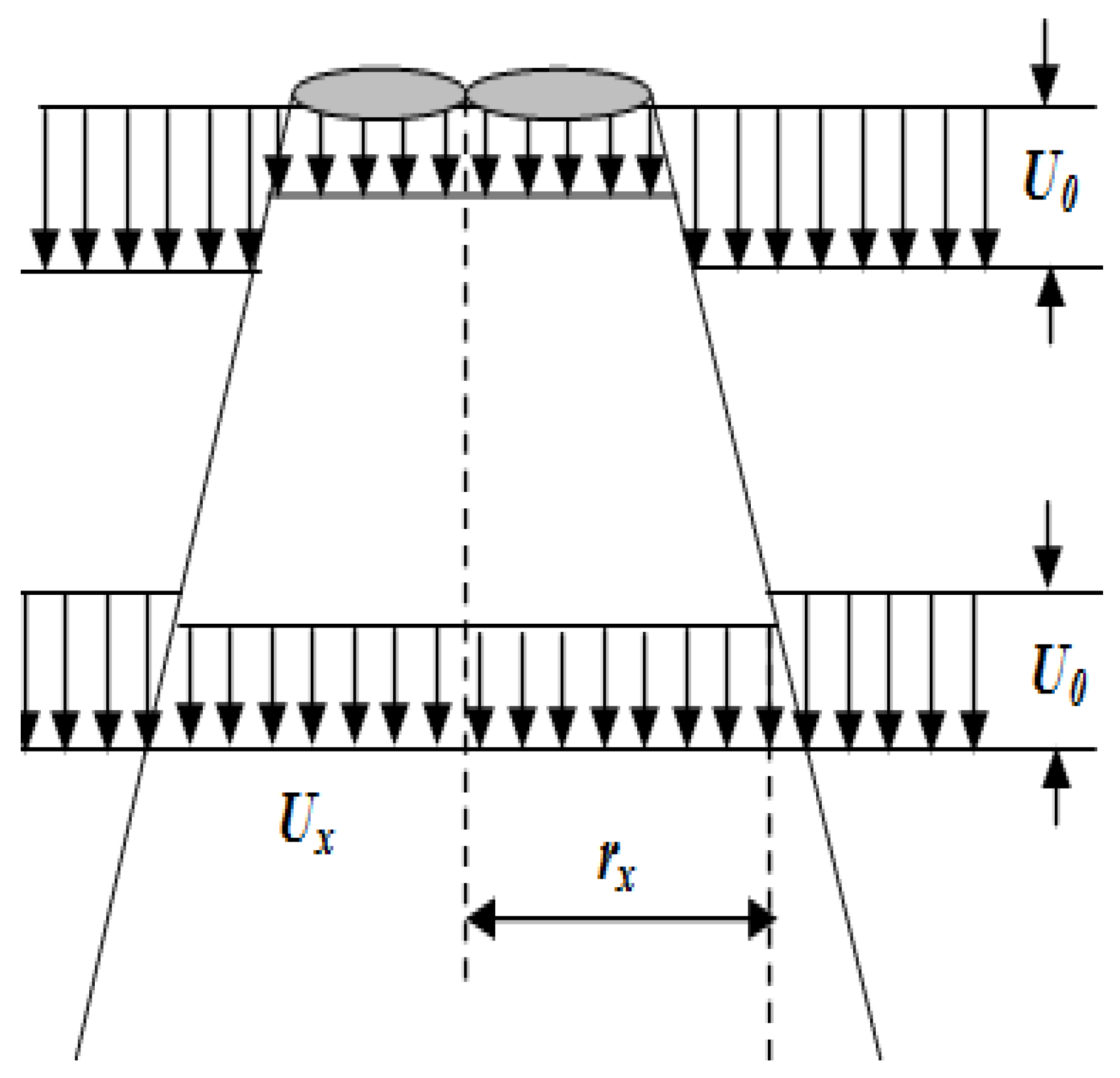
Jensen [22] developed a simple model to describe the variation in wind speed in the wake of a front turbine. Due to the simplicity of programming and ease of implementation offered by the Jensen model, many methods incorporate it to achieve optimal micro-location of wind turbines in a wind farm. As shown in Figure 1, in this model, the wind speed presented a “hat” profile in the wake [35].
The wind speed in the wake Uw is described as follows [36,37]:
where CT is the thrust coefficient, R is the blade radius of the wind turbine and rx is the radius of the wake at a distance x from the wind turbine that generated the wake.
Jensen [22] assumed that the increase in the wake radius rx was proportional to the position x, and it depends on the coefficient of wake expansion α in the following relation [38,39]:
Also, the entrainment coefficient α depends on the roughness of the ground Z0 and the height of the turbine Z:
2.1. Partial Wake Modeling within the Jansen Model
In a wind farm, we refer to the partial wake and its associated effects, where a portion of the actuator disk of a downstream wind turbine is influenced by the wake of another wind turbine in the Δrx zone, as illustrated in Figure 2.
In this figure, it is evident that the actuator disk of the downstream wind turbine is scanned at two different speeds: one without the wake effect, denoted as U0, and another with the wake effect, denoted as Ux. From this, we can deduce the relationship of the partial wake zone as follows:
2.2. Method for Determining the Region Impacted by a Partial Wake in the Jansen Model
In the partial wake, it is distinguished that the actuator disk of the downstream wind turbine operates in two different regions: one characterized by a wind speed deficit resulting in a partial reduction in developed power and another where the wind speed remains constant (Figure 3).
At a distance x, the wake surface Aw is
In addition, the surface AR of the actuator disc of the wind turbine is
3. Power Generated in the Case of a Partial Wake
The total power Ptot in the case of the partial wake can be calculated as the sum of the products of the partial powers and the ratios of the corresponding regions, which are as follows:
where , , , and represent the power without the wake effect, the power with the wake effect, the area ratio affected by the wake, and the area ratio not affected by the wake, respectively.
Approach to Estimating the Power Produced by a Wind Farm
In Figure 4, we present the proposed flowchart for determining the power developed when the wake affects a portion of the actuator disc of a downstream turbine. The program begins by identifying the zone where the partial wake operates and introducing the required parameters, such as the turbine’s thrust coefficient CT, the ground roughness Z0, and the upstream wind speed U0. If the condition of existence of the partial wake is confirmed, then the wind speed at each zone of the actuator disc, whether affected by the wake or not, is determined according to Equation (1). Otherwise, the wind speed remains constant. Subsequently, the developed power for each zone can be calculated using the power curve of the ENERCON E2 turbine.
Thus, the total power Ptot of a single turbine can be computed by summing the partial powers.
4. Results and Discussion
To perform the numerical simulations, it was important to represent the corresponding power curve of the ENERCON E2 wind turbine (see Figure 5) [40] with a polynomial equation as follows:
Equation (10) and the turbine data, with a diameter D = 82 m and a hub height Z = 85 m, were introduced in the program as indicated in the flowchart (Figure 4).
4.1. Interval of the Partial Wake at a Wind Farm
In a given wind farm, we considered that the typical longitudinal and transverse distances between the rows of turbines were to the order of 5 D (where D is the diameter of the turbine) (Figure 6). According to Jensen’s model [22], we could estimate the extent of the partial wake’s influence on neighboring rows of wind turbines using Equation (2), regardless of the wind speed. The calculated results indicate that the partial wake must verify the following criteria:
The investigation into the partial wake’s impact on the developed power was conducted for the ENERCON E2 wind turbine operating at a wind speed U = 6 m/s and ground roughness Z0 = 0.3 m. Calculations were carried out by varying only the region affected by the partial wake with the variation of the downstream distance x, ranging from 45 D to 60 D. The results obtained are presented in Table 1.
For different values of the position x, the wind speed in the wake gradually returned to 6 m/s far downstream. Furthermore, the radius of the wake expanded, gradually reaching the downstream wind turbines when starting from x = 50 D. As a result, the power output of a single wind turbine initially decreased, eventually stabilizing at a nearly constant value. This phenomenon can be attributed to the wind stabilizing at a specific level.
4.2. The Power Generated by the Wind Farm
As an application of this method, we propose a wind farm in given dimensions (60 D × 60 D), comprising 45 ENERCON E2 turbines distributed across 144 identical cells aligned with a predominant wind direction as shown in Figure 7. The symbol X denotes the position of each turbine in the wind farm.
With a uniform wind speed U = 6 m/s and a ground roughness Z0 = 0.3 m, the simulation results obtained, accounting for the partial wake effect, indicate that the calculated power output of the wind farm was 13,137 MW.
4.3. Validity Study
In order to study the validity of the proposed method, we replicated and integrated the previous works by Mosetti et al. [27], Zergane et al. [38], and Ituarte-Villarreal et al. [28], illustrated in Figure 8a–c, respectively, into our MATLAB program along with their operating conditions.
The results obtained from reproducing the previous works using the developed program are presented in Table 2.
As indicated in Table 2, the greatest percentage of power difference was recorded in the study by Zergane et al. [38] (4.03%), while the lowest was that of Mosetti [27] (1.98%). This can be explained as follows:
- −
- In Mosetti’s study [27], the 26 wind turbines arranged in the optimal configuration were more widely spaced in a park of 100 cells, resulting in less partial wake interference.
- −
- Conversely, in the study by Zergane et al. [38], the 55 wind turbines in the park were distributed across a dense arrangement of 144 cells, leading to increased interference among the wind turbines and consequently a significant partial wake effect.
It is important to note that in the study by Zergane et al. [38], the total power of the 45 wind turbines was lower than those calculated by Ituarté et al. [28] and Mosetti [27], who used 30 and 26 turbines, respectively. This difference can be attributed to the varying types of turbines used in each wind farm, as well as consideration of different wind speeds during the calculations.
5. Conclusions
In this study, we investigated the impact of a partial wake on the power generated by a wind farm. Previous studies have often neglected the partial wake, concentrating solely on the total wake when its expanding radius intersects the center of the downstream wind turbine’s rotor. However, in reality, both the total wake and partial wake consistently contribute to wind turbine interference. Using Jensen’s wake model, along with the characteristics of the ENERCON E2 wind turbine and wind farm data, we developed a Matlab program to calculate the total power. The results obtained revealed the following:
- −
- This method enables the determination of the range within which the partial wake operates. This range extended between 45.16 D and 56.49 D, thereby facilitating a more precise determination of the power developed by a wind farm at a given speed.
- −
- By comparing the results obtained in this study with those of previous works, it becomes apparent that the application of this method is more decisive in denser parks, where encounters with partial wakes are more frequent.
- −
- In a broader context, this method could be used as a reference tool for accurately evaluating the power produced by a wind farm.
Finally, as a perspective and continuation to this work, a more detailed study that considers the influence of wind turbine components, specifically the nacelle and the tower, could be conducted in the future. This would enable more precise prediction of the wind turbine power within a partial wake zone.
Author Contributions
Conceptualization, S.Z.; Software, N.M.; Validation, C.F.; Formal analysis, S.Z. and S.B.; Writing—original draft, S.Z.; Writing—review & editing, S.A. All authors have read and agreed to the published version of the manuscript.
Funding
This research received no external funding.
Data Availability Statement
The data presented in this study are available on request from the corresponding author.
Conflicts of Interest
The authors declare no conflict of interest.
List of Symbols
| AR | Actuator disk area (m2) |
| Aw | Wake area (m2) |
| CT | Thrust coefficient |
| D | Rotor diameter (m) |
| R | Rotor radius (m) |
| Power with wake effect (W) | |
| Power without wake effect (W) | |
| Ptot | Total power (W) |
| rx | Wake radius at x position (m) |
| Δrx | Area affected by the partial wake |
| x | Wake downstream position (m) |
| U | Wind speed (m/s) |
| Ux | Wind speed at x wake downstream position (m/s) |
| U0 | Wind speed without wake effect (3/s) |
| Wind speed in the wake (m/s) | |
| y | Distance between the centers of two neighboring wind turbines (m) |
| Z | Hub height (m) |
| Z0 | Ground roughness (m) |
| α | Entrainment coefficient |
| Surface swept by the partial wake (m2) |
References
- Korolev, V.G. Development prospects of wind energy in the Russian energy complex. Electr. J. 2022, 35, 107094. [Google Scholar] [CrossRef]
- Veena, R.; Manuel, S.M.; Mathew, S.; Petra, M.I. Wake induced Power Losses in Wind Farms. Int. J. Eng. Adv. Technol. 2020, 9, 2175–2180. [Google Scholar]
- Lin, J.; Wei, Z.; Wei, J.; Shen, W.Z. New engineering wake model for wind farm applications. Renew. Energy 2022, 198, 1354–1363. [Google Scholar] [CrossRef]
- Hu, W.; Huang, Q.; Wu, X.; Li, J.; Zhang, Z. Wind farm control and optimization. In Control of Power Electronic Converters and Systems; Academic Press: Cambridge, MA, USA, 2021; pp. 609–644. [Google Scholar]
- Coelho, P. The Betz limit and the corresponding thermodynamic limit. Wind Eng. 2023, 47, 491–496. [Google Scholar] [CrossRef]
- Gumilar, L.; Sholeh, M.; Triharto, R.; Rumokoy, S.N.; Monika, D.; Aji, A.F. Influence of Wind Turbine Pitch Angle on DFIG Output Stability under Load Changes. In Proceedings of the 2021 4th International Seminar on Research of Information Technology and Intelligent Systems (ISRITI), Yogyakarta, Indonisia, 16 December 2021; IEEE: Piscataway, NJ, USA, 2021; pp. 435–439. [Google Scholar]
- Lanchester, F.W. A contribution to the theory of propulsion and the screw propeller. J. Am. Soc. Nav. Eng. 1915, 27, 509–510. [Google Scholar] [CrossRef]
- Uchida, T. Effects of inflow shear on wake characteristics of wind-turbines over flat terrain. Energies 2020, 13, 3745. [Google Scholar] [CrossRef]
- Hertwig, D.; Gough, H.L.; Grimmond, S.; Barlow, J.F.; Kent, C.W.; Lin, W.E.; Robins, A.G.; Hayden, P. Wake characteristics of tall buildings in a realistic urban canopy. Bound. Layer Meteorol. 2019, 172, 239–270. [Google Scholar] [CrossRef]
- Peña, A.; Réthoré, P.E.; Van Der Laan, M.P. On the application of the Jensen wake model using a turbulence-dependent wake decay coefficient: The Sexbierum case. Wind Energy 2016, 19, 763–776. [Google Scholar] [CrossRef]
- Duc, T.; Coupiac, O.; Girard, N.; Giebel, G.; Göçmen, T. Local turbulence parameterization improves the Jensen wake model and its implementation for power optimization of an operating wind farm. Wind Energy Sci. 2019, 4, 287–302. [Google Scholar] [CrossRef]
- Thøgersen, E.; Tranberg, B.; Herp, J.; Greiner, M. Statistical meandering wake model and its application to yaw-angle optimisation of wind farms. J. Phys. Conf. Ser. 2017, 854, 012017. [Google Scholar] [CrossRef]
- Lopes, A.M.; Vicente, A.H.; Sanchez, O.H. Operation assessment of analytical wind turbine wake models. J. Wind Eng. Ind. Aerodyn. 2022, 220, 104840. [Google Scholar] [CrossRef]
- Barthelmie, R.; Larsen, G.; Frandsen, S.; Folkerts, L.; Rados, K.; Pryor, S.; Lange, B.; Schepers, G. Comparison of wake model simulations with offshore wind turbine wake profiles measured by sodar. J. Atmos. Ocean. Technol. 2006, 23, 888–901. [Google Scholar] [CrossRef]
- Ishihara, T.; Yamaguchi, A.; Fujino, Y. Development of a new wake model based on a wind tunnel experiment. Glob. Wind Power 2004, 105, 33–45. [Google Scholar]
- Yang, J.; Fang, L.; Song, D.; Su, M.; Yang, X.; Huang, L.; Joo, Y.H. Review of control strategy of large horizontal axis wind turbines yaw system. Wind Energy 2021, 24, 97–115. [Google Scholar] [CrossRef]
- Hansen, M.H. Using an Unsteady Panel Method with Fluid-Structure Interaction Problems. In IUTAM/IFToMM Symposium on Synthesis of Nonlinear Dynamical Systems: Proceedings of the IUTAM/IFToMM Symposium, Riga, Latvia, 24–28 August 1998; Springer: Dordrecht, The Netherlands, 2000; pp. 139–148. [Google Scholar]
- Crasto, G.; Gravdahl, A.R. CFD wake modeling using a porous disc. In Proceedings of the European Wind Energy Conference & Exhibition 2008, Brussels, Belgium, 31 March–3 April 2008; Volume 15. [Google Scholar]
- Crespo, A.; Hernandez, J.; Frandsen, S. Survey of modelling methods for wind turbine wakes and wind farms. Int. J. Prog. Appl. Wind Power Convers. Technol. 1999, 2, 1–24. [Google Scholar] [CrossRef]
- Ti, Z.; Deng, X.W.; Yang, H. Wake modeling of wind turbines using machine learning. Appl. Energy 2020, 257, 114025. [Google Scholar] [CrossRef]
- Huang, H.S. Distributed genetic algorithm for optimization of wind farm annual profits. In Proceedings of the 2007 International Conference on Intelligent Systems Applications to Power Systems, Kaohsiung, Taiwan, 5–8 November 2007; IEEE: Piscataway, NJ, USA, 2007; pp. 1–6. [Google Scholar]
- Jensen, N.O. A Note on Wind Generator Interaction; Technical Report; Riso-M-2411; Riso National Laboratory: Roskilde, Denmark, 1983. [Google Scholar]
- Zhang, S.; Gao, X.; Ma, W.; Lu, H.; Lv, T.; Xu, S.; Wang, Y. Derivation and verification of three-dimensional wake model of multiple wind turbines based on super-Gaussian function. Renew. Energy 2023, 215, 118968. [Google Scholar] [CrossRef]
- Feng, D.; Li, L.K.; Gupta, V.; Wan, M. Component wise influence of upstream turbulence on the far-wake dynamics of wind turbines. Renew. Energy 2022, 200, 1081–1091. [Google Scholar] [CrossRef]
- Hewitt, S.; Margetts, L.; Revell, A. Building a digital wind farm. Arch. Comput. Methods Eng. 2018, 25, 879–899. [Google Scholar] [CrossRef]
- Grady, S.A.; Hussaini, M.Y.; Abdullah, M.M. Placement of wind turbines using genetic algorithms. Renew. Energy 2005, 30, 259–270. [Google Scholar] [CrossRef]
- Mosetti, G.; Poloni, C.; Diviacco, B. Optimization of wind turbine positioning in large windfarms by means of a genetic algorithm. J. Wind Eng. Ind. Aerodyn. 1994, 51, 105–116. [Google Scholar] [CrossRef]
- Ituarte-Villarreal, C.M.; Espiritu, J.F. Optimization of wind turbine placement using a viral based optimization algorithm. Procedia Comput. Sci. 2011, 6, 469–474. [Google Scholar] [CrossRef]
- Marmidis, G.; Lazarou, S.; Pyrgioti, E. Optimal placement of wind turbines in a wind park using Monte Carlo simulation. Renew. Energy 2008, 33, 1455–1460. [Google Scholar] [CrossRef]
- Zergane, S.; Smaili, A.; Masson, C. Optimization of wind turbine placement in a wind farm using a new pseudo-random number generation method. Renew. Energy 2018, 125, 166–171. [Google Scholar] [CrossRef]
- Lio, W.H.; Larsen, G.C.; Thorsen, G.R. Dynamic wake tracking using a cost-effective LiDAR and Kalman filtering: Design, simulation and full-scale validation. Renew. Energy 2021, 172, 1073–1086. [Google Scholar] [CrossRef]
- He, R.; Yang, H.; Lu, L. Optimal yaw strategy and fatigue analysis of wind turbines under the combined effects of wake and yaw control. Appl. Energy 2023, 337, 120878. [Google Scholar] [CrossRef]
- Vad, A.; Tamaro, S.; Bottasso, C.L. A non-symmetric Gaussian wake model for lateral wake-to-wake interactions. J. Phys. Conf. Ser. 2023, 2505, 012046. [Google Scholar] [CrossRef]
- Scott, R.; Viggiano, B.; Dib, T.; Ali, N.; Hölling, M.; Peinke, J.; Cal, R.B. Wind turbine partial wake merging description and quantification. Wind Energy 2020, 23, 1610–1618. [Google Scholar] [CrossRef]
- Katic, I.; Hojstrup, J.; Jensen, N.O. A Simple Model for Cluster Efficiency. In Proceedings of the European Wind Energy Association Conference and Exhibition, Rome, Italy, 7–9 October 1986; Volume 1, pp. 407–410. [Google Scholar]
- Seim, F.; GravdahL, A.R.; Adaramola, M.S. Validating of kinematic wind turbine wake models in complex terrain using actual wind farm production data. Energy 2017, 123, 742–753. [Google Scholar] [CrossRef]
- Sun, H.; Gao, X.; Yang, H. Validations of three-dimensional wake models with the wind field measurements in complex terrain. Energy 2019, 189, 116213. [Google Scholar] [CrossRef]
- Zergane, S.; Amroune, S.; Rokbi, M.; Guesmia, S. New study on the extension of a current wind farm, case of Kaberten park in Algeria. Turk. J. Computer Math. Educ. 2022, 13, 428–434. [Google Scholar]
- Tong, W.; Chowdhury, S.; Zhang, J.; Messac, A. Impact of different wake models on the estimation of wind farm power generation. In Proceedings of the 12th AIAA Aviation Technology, Integration, and Operations (ATIO) Conference and 14th AIAA/ISSMO, Multidisciplinary Analysis and Optimization Conference, Indianapolis, IN, USA, 17–19 September 2012; p. 5430. [Google Scholar]
- Available online: https://fr.wind-turbine-models.com/turbines/550-enercon-e-82-e2-2.300/ (accessed on 1 January 2023).
Figure 1.
Jensen wake model.

Figure 2.
Wind turbine downstream affected by the partial wake in the Δrx zone.

Figure 3.
(a) The upstream wind turbine (right) generates a wake that partially influences the downstream wind turbine (left). (b) Detailed partial wake area.
Figure 3.
(a) The upstream wind turbine (right) generates a wake that partially influences the downstream wind turbine (left). (b) Detailed partial wake area.


Figure 4.
Proposed flowchart for the numerical simulation.

Figure 5.
Power characteristic curve of the E2 ENERCON turbine.

Figure 6.
Wake expansion.

Figure 7.
Distribution of wind turbines in the proposed wind park according to the predominant wind direction, indicated by the arrows.
Figure 7.
Distribution of wind turbines in the proposed wind park according to the predominant wind direction, indicated by the arrows.

Figure 8.
Optimal arrangement: (a) Moseti et al. [27], (b) Zergane et al. [38], and (c)—Ituarte-Villarreal et al. [28].


Table 1.
Characteristics and data of the ENERCON E2 turbine.
| x (m) | U (m/s) | rx (m) | P (kW) |
|---|---|---|---|
| 45 D | 6 | 367.743 | 316.027 |
| 50 D | 5.98 | 367.74 | 314.715 |
| 55 D | 5.99 | 440.35 | 314.217 |
Disclaimer/Publisher’s Note: The statements, opinions and data contained in all publications are solely those of the individual author(s) and contributor(s) and not of MDPI and/or the editor(s). MDPI and/or the editor(s) disclaim responsibility for any injury to people or property resulting from any ideas, methods, instructions or products referred to in the content. |
© 2024 by the authors. Licensee MDPI, Basel, Switzerland. This article is an open access article distributed under the terms and conditions of the Creative Commons Attribution (CC BY) license (https://creativecommons.org/licenses/by/4.0/).
Share and Cite
MDPI and ACS Style
Zergane, S.; Farsi, C.; Amroune, S.; Benkherbache, S.; Menasri, N. A New Study on the Effect of the Partial Wake Generated in a Wind Farm. Energies 2024, 17, 1498. https://doi.org/10.3390/en17061498
AMA Style
Zergane S, Farsi C, Amroune S, Benkherbache S, Menasri N. A New Study on the Effect of the Partial Wake Generated in a Wind Farm. Energies. 2024; 17(6):1498. https://doi.org/10.3390/en17061498
Chicago/Turabian StyleZergane, Said, Chouki Farsi, Salah Amroune, Souad Benkherbache, and Noureddine Menasri. 2024. "A New Study on the Effect of the Partial Wake Generated in a Wind Farm" Energies 17, no. 6: 1498. https://doi.org/10.3390/en17061498
Note that from the first issue of 2016, this journal uses article numbers instead of page numbers. See further details here.