Article

Research on the Law of Layered Fracturing in the Composite Roof Strata of Coal Seams via Hydraulic Fracturing

1
School of Geology and Environment, Xi’an University of Science and Technology, Xi’an 710054, China
2
CCTEG Xi’an Research Institute (Group) Co., Ltd., Xi’an 710077, China
*
Author to whom correspondence should be addressed.
Energies 2024, 17(8), 1941; https://doi.org/10.3390/en17081941
Submission received: 6 March 2024 / Revised: 8 April 2024 / Accepted: 11 April 2024 / Published: 19 April 2024

Abstract

:
Horizontal wells within the roof are an effective method to develop gas in broken and soft coal seams, and layer-penetrating fracturing is a key engineering method for the stimulating of horizontal wells within the roof of a coal seam. To understand the propagation law of fracture in the composite roof of coal seams, this study conducted research using numerical simulation and physical similarity simulation methods. Furthermore, engineering experiments were carried out at the Panxie coal mine in the Huainan Mining Area and the Luling coal mine in Huaibei Mining Area, to further validate this technology. The numerical simulation results indicated that fracture within the coal seam roof can propagate from the roof to the target coal seam, effectively fracturing the coal seam. Due to the coal seam’s plasticity being greater than that of the roof mudstone, the coal seam forms a broader fracture than the roof. With the increase in pseudo roof mudstone thickness and being under constant fracturing displacement, the energy consumed by the pseudo roof mudstone during fracturing causes a decrease in pore pressure when fracture extends to the coal seam, resulting in a reduction in fracture width. Therefore, the pseudo roof mudstone is an adverse factor for the expansion of hydraulic fracturing. Physical similarity simulation results demonstrated that when horizontal boreholes were arranged within the siltstone of the coal seam roof, were under reasonable vertical distance and high flow rate fracturing via fluid injection conditions, and if the coal seam had a thin pseudo roof mudstone, the fracture could propagate through the direct roof-pseudo roof interface and the pseudo roof-coal seam interface, extending to the lower coal seam. The fracture form was curved and had irregular vertical fractures, indicating that hydraulic fracturing can achieve production enhancement and the transformation of soft and hard coal seams. However, when the coal seam had a thick pseudo roof mudstone, the mudstone posed strong resistance to hydraulic fracturing, making it difficult for the fracture to propagate to the lower coal seam. Therefore, the pseudo roof mudstone plays a detrimental role in hydraulic fracturing and the production enhancement of coal seams. The engineering verification conducted at Panxie coal mine and Luling coal mine showed that by utilizing a construction drainage rate of 7.5 cubic meters per minute at Panxie coal mine, the maximum fracture length reached 218.3 m, with a maximum fracture height of 36.8 m. The maximum daily gas production of a single well reached 1450 cubic meters per day, with a total gas extraction volume of 43.62 × 10⁴ cubic meters across 671 days. At Luling coal mine, utilizing a construction drainage rate of 10 cubic meters per minute, the maximum fracture length reached 169.1 m, with a maximum fracture height of 20.5 m. The maximum daily gas production of a single well reached 10,775 cubic meters per day, with a total gas extraction volume of 590 × 104 cubic meters for 1090 days. This indicated that the fracture within the roof of coal seams can penetrate the composite roof of coal seams and extend to the interior of the coal seams, achieving the purpose of transforming fractured and low-permeability coal seams and providing an effective mode of gas extraction.

1. Introduction

Gas extraction is an essential technical approach for ensuring coal mine safety [1,2]. Conventional gas extraction drilling in broken and soft coal seam faces challenges [3,4,5,6,7,8,9]. Moreover, due to the low gas concentration, the extracted gas does not meet industrial standards for development and utilization, resulting in direct atmospheric emissions and environmental pollution. The gas extraction volume in Chinese coal mines in 2020 reached 12.8 billion cubic meters, with a utilization rate of only 44.8% [10,11]. The average gas extraction concentration value in Panxie coal mine was 25.73%, which did not meet the lower limit of 30% for gas utilization concentration. The horizontal wells within the roof are an effective method to develop gas in broken and soft coal seams, and layer-penetrating fracturing is a key engineering method in the stimulating of horizontal wells within the roof of a coal seam [12,13,14,15]. For broken and soft coal seams, both domestic and international studies have been conducted on the theory of layer fracturing in horizontal wells within the roof using methods such as physical simulation or numerical simulation. Jiang Zaibing [16,17,18] and others utilized theoretical analysis and numerical simulation methods to study fragmented and low-permeability coal seams in the Huainan region of China. They compared the propagation characteristics of fractures under different stress states and concluded that the in situ stress is a key controlling factor for fracture propagation across layers. Hu Xinting [19,20,21,22,23] and others found that under conditions of reasonable construction displacement and horizontal well spacing, fractures can extend from the high-stress roof into the low-stress coal seam. The effectively supported fractures formed in the roof can provide pathways for coalbed gas to enter the wellbore. Additionally, they observed that larger injection volumes of fracturing fluid led to greater depths of fracture propagation across interfaces, and during fracture propagation across layers, the height and length of fractures within the roof were greater than those within the coal seam. They conducted physical simulation experiments on layer fracturing in horizontal wells and studied the expansion laws of fractures and the sensitivity factors of layer fracturing effects. The results indicated that the horizontal well position, injection volume, perforation method, and vertical-horizontal stress differential are four important factors influencing the morphology of fractures during layer fracturing in horizontal wells. Previous studies often assumed that the roof of the coal seam is a single rock layer, and models were constructed in the form of “roof-coal seam”. However, based on underground exposure and analysis of surface drilling cores, it is commonly observed that coal seams are not directly in contact with the immediate roof; instead, there is typically a layer of carbonaceous mudstone pseudo roof, forming a composite roof of the coal seam. Therefore, hydraulic fracturing must consider the influence of the mudstone pseudo roof on fracture propagation. The article was based on the combined rock mechanics characteristics of actual fractured and soft coal seams and overlying strata. It employed numerical simulation and physical similarity modeling methods to study the interlayer characteristics of hydraulic fracturing fractures in composite roof strata. The research was validated by using Panxie coal mine in Huainan Mining Area and Luling coal mine in Huaibei Mining Area as examples, providing a basis for the construction of horizontal well hydraulic fracturing in fractured and soft coal seam roofs.

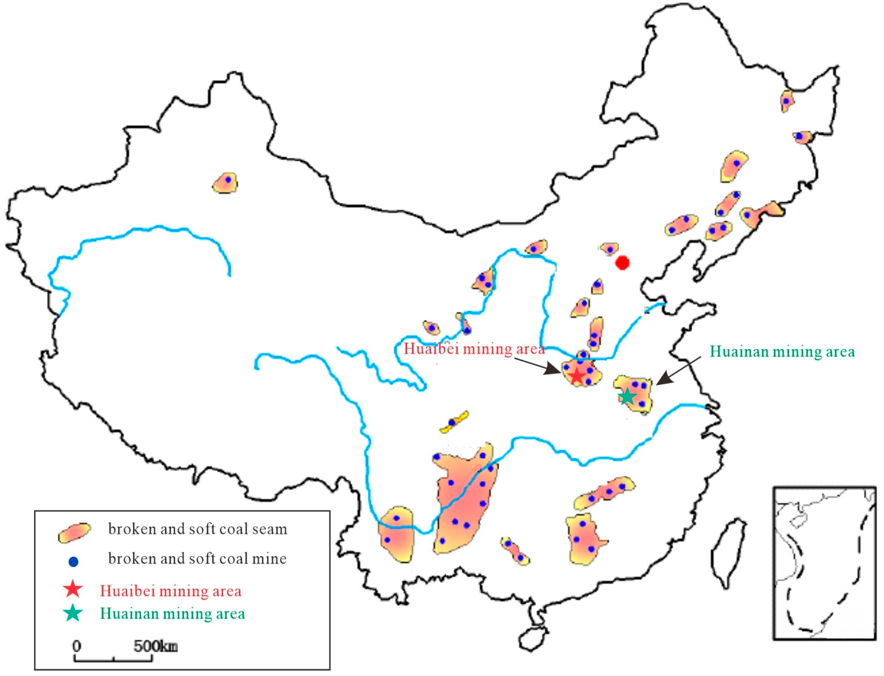
2. Engineering Background

The main coal-bearing basins in China have undergone multiple episodes of tectonic activity in geological history, leading to the destruction of the original structure of coal seams and the widespread development of fragmented, poorly permeable coal seams [24] (Figure 1). This is illustrated by the broken and soft coal seams using typical examples from the mining areas of Huainan and Huaibei in Anhui Province.

2.1. Geological Background

The Huainan mining area is classified into the Huaihe River Formation Subzone of the North China Stratigraphic Zone, and the Huainan Stratigraphic Subzone. The main coal seams are primarily distributed in the Shanxi, Lower Shihezi, and Upper Shihezi formations of the Permian system. The main 13-1 coal seam is located in the middle part of the Lower Shihezi Formation, with an average thickness of 6.70 m and is mineable throughout the entire area. It contains multiple layers of gangue and has a complex coal seam structure. The pseudo roof consists of black carbonaceous mudstone, while the immediate roof is composed of deep gray siltstone; the overlying roof is made up of light gray fine-grained sandstone. The floor is composed of deep gray mudstone or sandy mudstone, with visible plant fossils. The parameters of the coal seam and surrounding rocks are listed in Table 1.
The 13-1 coal seam has undergone intense ductile deformation and transformation, predominantly consisting of coking coal and splint coal, with only occasional instances of granular coal in the upper and lower parts of the seam. The coking coal and splint coal have a coal body strength coefficient of 0.32–0.50, resulting in coal fragmentation. The gas content ranges from 10.78 to 17.22 cubic meters per ton, with an average of 15.28 cubic meters per ton.

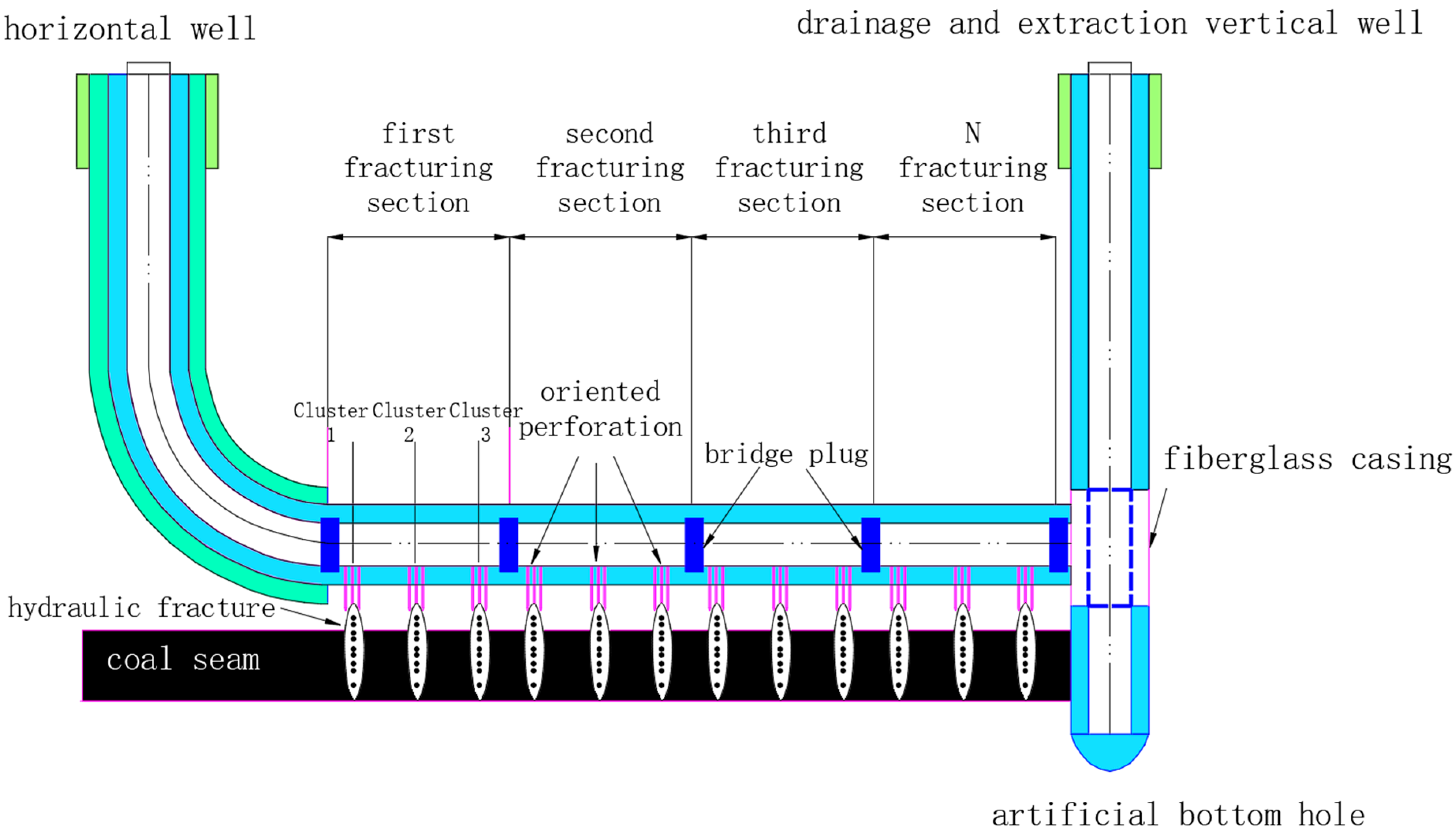
2.2. The Gas Extraction Model of Sectional Hydraulic Fracturing in the Rock of the Coal Seam Roof

Sectional hydraulic fracturing is a technique employed to efficiently extract coalbed methane from coal seams, particularly in areas characterized by broken, soft, and low-permeability coal mine zones. This technique involves implementing a horizontal well in the roof rock layer adjacent to the coal seam. Directional perforation is performed downwards, followed by sectional fracturing to establish connectivity between the coal seam and its roof rock. The resulting fracture extends across the coal-rock boundary and connects with the shaft via the lower coal seam. The relatively high brittleness of the roof rock facilitates the formation of lengthy fractures, enhancing the effectiveness of the fracturing process and enabling efficient extraction of coalbed methane. Figure 2 depicts the roof rock-in sectional hydraulic and horizontal well fracturing mode. This technique has been successfully employed in the Panxie mine for coalbed methane extraction from the No. 13-1 coal seam, which is soft, broken, and has low permeability. The application of sectional hydraulic fracturing in the rock of the coal seam roof has significantly increased methane concentration during extraction, mitigated methane emissions, and provided a reliable source of clean energy.
The in situ stress testing was conducted strictly following the “Specification of hydraulic fracturing and overcoring method for in-situ stress measurement” (DB/T 14-2018) [25]. After the observation of static water level, the underground fracturing equipment was installed, and the following steps were sequentially carried out: packer pressurization and sealing, hydraulic fracturing, fracture reopening, water pressure-induced fracture imaging, determination of fracturing parameters, and determination of the magnitude and direction of in situ stress. The maximum horizontal principal stress of the Panxie mine was measured to be 16.30 MPa, the minimum horizontal principal stress was 14.00 MPa, and the vertical stress was 17.74 MPa. The vertical stress was greater than the horizontal stresses. Therefore, hydraulic fracturing of the segmented and clustered sections of the roof coal seam resulted in the formation of a vertical fracture network. Due to the higher elastic modulus of the roof strata, the horizontal stress experienced by the roof was generally greater than that of the coal seam, which allowed the fractures formed in the roof to extend into the coal seam, thereby improving the permeability enhancement effect of the coal seam [26].

3. Numerical Model

To investigate the propagation behavior of fractures at the rock-coal boundary and achieve optimal construction results, a numerical model was developed using XFEM software 2020. This model focused on a horizontal well situated in the rock above a coal seam roof. The utilization of XFEM software offers several advantages, such as accurate calculation results and low computational requirements. This software enables simulation and analysis of various physical parameters related to reservoirs and hydraulic fracturing construction. Consequently, it serves as an effective tool for studying fracture behavior at the rock-coal boundary and optimizing the hydraulic fracturing process while minimizing redundancy.

3.1. Model Parameter Settings

Based on the ABAQUS 2020 finite element numerical simulation software, the method of extended finite element method (XFEM) was applied to simulate the cross-layer propagation law of fracture. The established two-dimensional numerical simulation model is shown in Figure 3, with a width and height of 40 m × 40 m. Quadrilateral elements were used with each element having a width and height of 0.5 m, resulting in a total of 6400 elements in the model. The model was divided from top to bottom into 5 layers, namely: upper old fine-grained sandstone 15 m, direct upper siltstone 4 m, pseudo upper mudstone 1 m, coal seam 6 m, and lower mudstone 14 m. The horizontal well was positioned within the fine sandstone roof 1 m above the coal seam. The diameter of the borehole was 0.20 m. XFEM elements were inserted as initiation points for fracturing, simulating a downward perforation depth of 0.5 m. Water was chosen as the fracturing fluid with a pumping rate of 0.5 m3/min, fluid viscosity of 1.0 Pa·s, and a fracturing time of 100 s. The selection of parameters was based on the measured rock mechanics parameters, permeability, and in situ stress data from the Panxie mine in the Huainan Mining Area.
To accurately represent the cohesive characteristics of the interface, zero-thickness cohesive element layers were used in the numerical simulation model to characterize its properties. A total of four zero-thickness cohesive element layers were inserted into the model to represent the coal-rock interface. Due to the development of coal cleats and the smooth surface treatment, the bonding strength on the coal side was significantly lower than that on the mudstone and sandstone side. Obtaining rock samples containing the coal-roof interface is challenging in actual ground drilling processes, especially for coal seams with fragmented and soft structures. Based on previous research by scholars [27,28,29], the following interface strengths were set from top to bottom: a tensile strength of 4 MPa and shear strength of 9 MPa for the fine-grained sandstone to siltstone interface; a tensile strength of 3 MPa and shear strength of 7 MPa for the siltstone to mudstone interface; and a tensile strength of 1 MPa and shear strength of 2 MPa for the coal to mudstone interface. Observation points A and B were respectively located at the injection point of the sandstone roof and the middle of the coal seam to track the variation in rock fracture width during the hydraulic fracturing process. Fracturing patterns formed by the model at different time steps were extracted to analyze the propagation laws of cross-layer fractures. These parameters are listed in Table 2.

3.2. Numerical Simulation Results

Figure 4 illustrates the progressive nature of fracture expansion. During the initial stage, fractures predominantly propagated within the sandy mudstone layer of the coal seam’s roof strata. At this point, the fracture extended upwards along the vertical height to cover the roof sandstone and the underlying coal seam simultaneously, with a relatively fast expansion rate. When the fracture height extended to the upper interface, the pressure inside the fracture made it difficult to open the roof of fine sandstone. Under the induction effect of directional perforation, the fracture propagated downwards, encountering significant resistance at the direct roof-pseudo roof interface (sandstone-mudstone interface). When the stress reached a certain level, the fracture penetrated through the direct roof-pseudo roof interface (sandstone-mudstone interface); when the fracture reached the pseudo roof-coal seam interface, the resistance generated was smaller, ultimately penetrating the coal seam interface to fully open up the coal seam.
Through the analysis of statistical data from monitoring the width of points of fracture, as shown in Figure 5, it can be observed that due to the higher plasticity of the coal seam compared to the overlying mudstone, wider fractures can be formed than those in the overlying strata.
The influence of different mudstone thicknesses on the penetration of fractures was analyzed, with mudstone pseudo roof thicknesses set at 1 m, 2 m, 3 m, and 4 m. By applying numerical simulation methods, the development rules of the width of immediate coal seam roof fractures were compared under different conditions of the pseudo roof thickness in mudstone. It can be seen that as the thickness of the mudstone pseudo roof increased, the width of fractures in the overlying strata and within the coal seam gradually decreased. Specifically, the width of fractures in the coal seam roof initially grew rapidly, but slowed down in the later stage; the final fracture width was negatively correlated with the thickness of the mudstone pseudo roof, as shown in Figure 6.
From Figure 7, it can be seen that with the increase in mudstone pseudo roof thickness, the width of fractures within the coal seam gradually decreased, and the time taken for fractures to develop to the center of the coal seam (point B) increased.
From Figure 8, it can be seen that with the increase in mudstone pseudo roof thickness, the width of fractures within the coal seam gradually decreased.
From Figure 9, it can be observed that with the increase in mudstone pseudo roof thickness, under constant fracturing displacement, the pore pressure in the formation gradually decreased.
The numerical simulation method simulated the penetration and extension law of fracture at the boundary of coal-rock after fracturing in the roof stratum. It was proven that the fracture in the roof stratum could extend to the coal seam. The fracture within the coal could spread rapidly, although due to the higher plasticity of the coal seam compared to the overlying mudstone, the fracture width of the coal seam was wider than that of the roof stratum.
With the increase in the false mudstone roof thickness, under the condition of constant fracturing volume, the width of fractures in the coal seam decreased. The reason for this analysis was that the initiation time of the fracture at the interface between the immediate roof and the pseudo roof (sandstone-mudstone interface) increased during the fracturing process, resulting in initially larger widths of roof fractures. After the fracture of the mudstone pseudo roof, the energy loss caused a rapid decrease in the growth rate of the fracture width in the later stage.
The width of fractures in the coal seam roof initially increased rapidly and then slowed down, with the final fracturing width showing a negative correlation with the thickness of the false mudstone roof. The reason for this analysis was that the fracturing process consumed certain kinetic energy in the fracture of the mudstone pseudo roof, leading to a reduction in pore pressure when the fractures extended into the coal seam, and consequently, a decrease in fracture width. Therefore, the mudstone pseudo roof was an unfavorable factor for the expansion of hydraulic fracturing fractures.

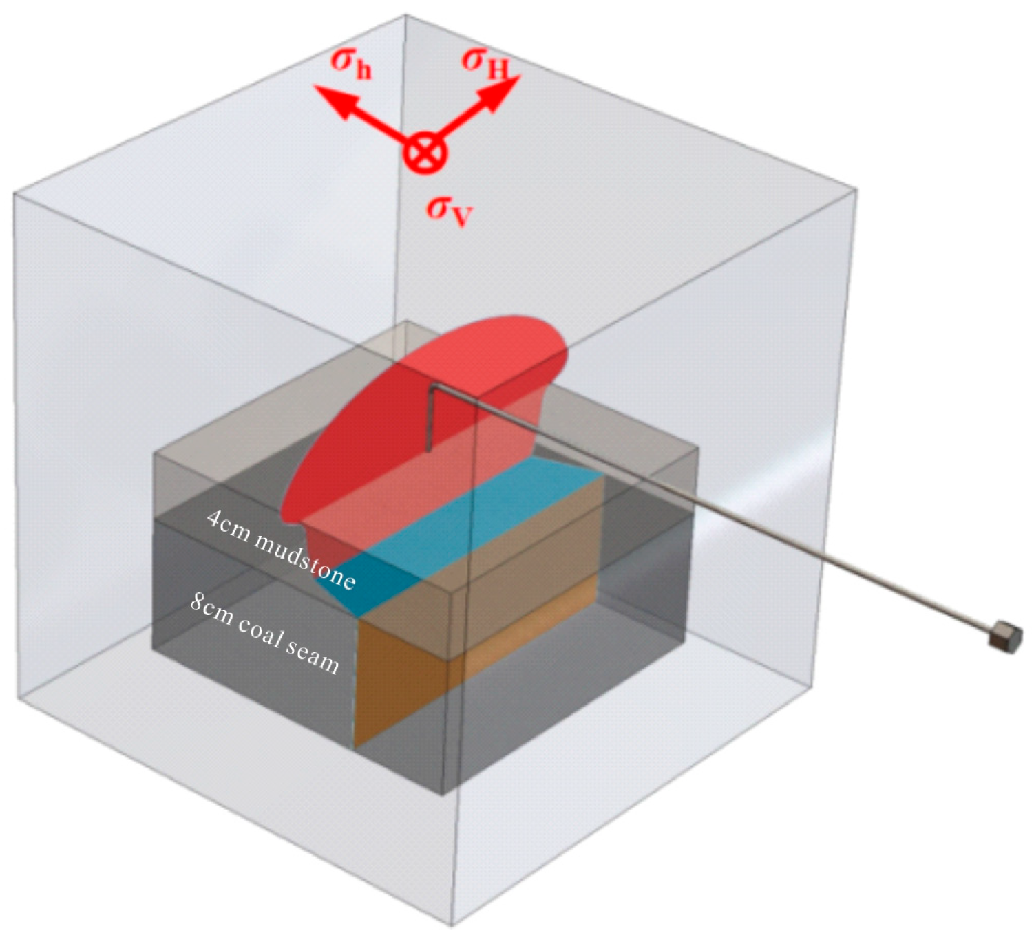
4. Physical Similarity Models

To verify the accuracy of the numerical simulation of fracture propagation in horizontal wells, two sets of indoor physical similarity simulation studies were conducted to demonstrate the characteristics of fracture propagation. The experiments were carried out in the Rock Mechanics Laboratory at the China University of Petroleum (Beijing, China).

4.1. The Fabrication of Physical Similarity Models

By conducting indoor physical simulation experiments on the hydraulic fracturing of horizontal coal seam roof boreholes, the study investigated the propagation laws and layer-penetrating mechanisms of hydraulic fracturing in coal rock layers. The No. 13-1 coal seam in the Huainan Mining Area is often accompanied by a layer of mudstone or sandy mudstone pseudo roof, with a thickness generally ranging from 0.5 to 2.0 m. Therefore, the physical similarity simulation experiments in this study considered the influence of mudstone interlayers on fracture propagation and conducted two sets of triaxial confinement physical simulation experiments with different thicknesses of mudstone pseudo roof. The schematic diagram of the physical simulation experiment plan is shown in Figure 10a, where the horizontal wellbore was set inside the model roof, 40 mm vertically above the coal seam, parallel to the coal rock interface and the direction of minimum horizontal principal stress, with a vertical downward perforation of 1 cm at the front end of the wellbore. To simulate the real effect of strata fracturing, a physical model based on the “roof-mudstone pseudo roof-coal seam” bonding with rock mechanics strength was established, with the dimensions of 300 mm × 300 mm × 300 mm. The coal seam thickness in the physical model was kept constant at 8 cm, while the thicknesses of the mudstone pseudo roof in the two groups of experiments were 4 cm and 6 cm, respectively, corresponding to the roof thicknesses of 18 cm and 16 cm. Acoustic emission monitoring devices were embedded in the roof as shown in Figure 10b. Coal seam and roof rock samples from the Huainan Mining Area were collected, and the mechanical properties of the rocks under true triaxial conditions were tested. Based on the mechanical parameters of the coal and rock samples, and following the principle of similarity, the reasonable proportions of similar materials were determined to prepare the coal-rock composite fracturing specimens. The optimal formulation for the roof rock layer was determined based on the following mechanical parameters of the coal seam and roof: the coal sample was selected to be consistent with the parameters of the target coal seam; mudstone pseudo roof material was prepared by mixing cement and quartz sand in a 1:1 ratio with water (using sand with a grain size of 70 to 100 mesh); and the roof material was prepared by mixing cement and quartz sand in a 1:1.5 ratio with water (using sand with a grain size of 40 to 70 mesh). The measured values of the rock parameters are shown in Table 3.

4.2. Quality Control and Uncertainty Discussion

Between the sandstone and mudstone pseudo roof and between the mudstone pseudo roof and the coal seam, there exists a distinct lithological interface, which acts as a weak plane and often affects the expansion of hydraulic fractures. In this experiment, the lithological interfaces were bonded using Yunshi adhesive. The shear strength of the sandstone-mudstone pseudo roof interface was 3 MPa, with a tensile strength of 1.5 MPa, while the mudstone pseudo roof-coal seam interface had a shear strength of 2 MPa and a tensile strength of 1.0 MPa. Although the bonding strength of the interfaces did not perfectly match the strength of actual rocks, it effectively reflected the influence of lithological interfaces on the expansion of hydraulic fractures. Under true indoor triaxial hydraulic fracturing simulation conditions, the effect of weak lithological planes on hydraulic fracture propagation can be fully demonstrated, leading to systematic understanding [30,31].
To eliminate uncertainties, two specimens were processed in the same batch, including material ratio, curing temperature, humidity, and other factors, to eliminate the influence on the mechanical properties of the specimen material. Additionally, to improve the accuracy of the experimental results, several measures were taken to strengthen specimen processing, minimizing potential interference factors and experimental errors:
(1)
Different bonding strengths between the rock layers’ interfaces may have subtle effects on the expansion of fractures crossing the interface. Therefore, during model preparation, the pouring procedure and method were ensured to be identical, and the coal and sandstone original rock samples were taken from the same location. The bonding materials used were strictly uniform, and the thickness of the Baiyun adhesive was kept consistent to eliminate differences in interface bonding strength.
(2)
The nonverticality of the horizontal wellbore with respect to the specimen boundary may affect the distance between the horizontal well fracture point and the coal seam, thereby affecting the test results. Thus, during wellbore processing, efforts were made to ensure that the wellbore was completely vertical with respect to the specimen boundary, reducing the influence of wellbore inclination. Variations in the length of the cut when precutting the fractures for inducing hydraulic fracturing may also affect the test results. Therefore, the same cutting method and procedure were employed for manually precutting the fractures to ensure that the precut length of the specimens was consistent.
(3)
The application of confining pressure was achieved through triaxial loading plates. Due to the uneven surface treatment of the specimens, the force actually applied to the specimen surface may be unevenly distributed, leading to stress concentration and affecting the test results. Hence, after the completion of horizontal wellbore processing, each face of the specimen was polished to smoothness to eliminate the influence of local stress.

4.3. Physical Simulation Experimental Conditions and Parameters

The fracturing fluid used was red clear water fracturing fluid. The fracturing fluid displacement was set at 20 mL/min. Three-way confining pressure was applied based on the actual geological conditions in the Huainan area, with a vertical stress of 17 MPa, a maximum horizontal principal stress of 15 MPa, and a minimum horizontal principal stress of 13 MPa. The pressure was increased gradually from high to low at regular intervals, and to better simulate the in situ stress environment, the pressure was stabilized for approximately 20 min after reaching the set value before the fracturing simulation began.

4.4. Physical Similarity Simulation Experiment Procedure

(1)
1# piece
The experiment was conducted with a displacement rate of 20 mL/min. At 200 s, hydraulic fractures occurred inside the top plate of the specimen, with a fracture pressure of 12 MPa. Subsequently, there was a certain degree of pressure fluctuation during the injection. At 360 s, shale started to fracture with a fracture pressure of 11.5 MPa. At 935 s, cleavage in coal rocks occurred with a fracture pressure of 9.3 MPa. The pressure then remained around 9.3 MPa until the end of the experiment.
(2)
2# piece
The experiment was conducted with a displacement rate of 20 mL/min. At 150 s, hydraulic fractures occurred inside the top plate of the specimen, with a fracture pressure of 14.3 MPa. Subsequently, the injection pressure decreased. At 189 s, shale started to fracture with a fracture pressure of 9.2 MPa. The pressure gradually increased thereafter. At 650 s, the interface between sand and mudstone fractured, and the pressure fluctuated around 12 MPa until the end of the experiment.

4.5. The Results of the Physical Similarity Model

The results of the physical similarity simulation experiment for 1# piece are shown in Figure 11. The fracture formed by hydraulic fracturing is delineated by the yellow dashed lines in the figure. It can be observed that the fracture initiated from the bare-eye section within the borehole and extended downwards, successfully crossing the immediate roof-pseudo roof interface (sandy mudstone-mudstone). The hydraulic fractures changed direction at the cementation interface between the mudstone and coal rock, continuing to penetrate into the coal seam. Eventually, the fractures penetrated through the coal rock, resulting in an overall staircase-like pattern. The interpretation of acoustic emission monitoring is presented in Figure 12, showing the formation of smaller elliptical fracture within the roof and a clear separation of the coal seam directly below the borehole, indicating significant interlayer fracturing.
The results of the physical similarity simulation experiment for 2# piece are shown in Figure 13, and the interpretation of the acoustic emission monitoring is presented in Figure 14. The fracture in Test Specimen 2 initiated from the bare-eye section within the borehole and formed a larger elliptical fracture within the roof. The downward extension of the fracture did not penetrate the interbedded mudstone layer. The hydraulic fractures propagated along the interface between the mudstone layer and the sandstone layer of the roof, eventually penetrating through the specimen. As a result, the hydraulic fractures did not affect the coal seam, and the overall fracture pattern appeared as a T-shaped fracture.
From the experimental process, it can be concluded that when horizontal boreholes were arranged within the sandy mudstone of the fractured coal seam roof, were under conditions of reasonable vertical distance and high-volume fracturing fluid injection, and if the coal seam had a thin pseudo roof of mudstone (pseudo roof thickness not exceeding 4 cm), the fracture can propagate through the immediate roof-pseudo roof interface (sandy mudstone-mudstone interface) and the pseudo roof-coal seam interface (mudstone-coal seam interface), extending into the underlying coal seam. The fracture formed a curved and irregular vertical fracture, indicating that hydraulic fracturing can achieve the goal of enhancing production and transforming soft and hard coal seams. However, when the coal seam had a thick mudstone pseudo roof (mudstone pseudo roof thickness of 6 cm or more), the mudstone presented strong resistance to hydraulic fracturing, making it difficult for the fracture to propagate into the underlying coal seam. Thus, the mudstone pseudo roof acted as a disadvantageous factor for hydraulic fracturing and production enhancement in the coal seam.

5. Engineering Application

The horizontal well gas control technology for coal seam roofs has been successfully applied in several soft- and low-permeability coal mining areas in China, such as the Huainan and Huaibei mining areas in Anhui Province, and the Baode mining area in Shanxi Province. This technology provides strong technical support for achieving large-scale gas extraction and utilization of fragmented and low-permeability coal seams, as well as the goal of comprehensive gas extraction coverage in coal mines. The following is an explanation using the typical examples of the Huainan and Huaibei mining areas in Anhui Province.

5.1. Panxie Coal Mine of Huainan Mine Area

In order to address the low efficiency of gas drainage and the tight mining schedule in the Panxie coal mine, a set of U-shaped wells was constructed above the 13,015 working face at a distance of 80 m from the return airway. The horizontal section of well XX-1L had a length of 1066 m, which was divided into 12 segments for hydraulic fracturing. The spacing between each segment ranged from 62 to 150 m. Each segment was perforated once, and the average injection rate for hydraulic fracturing was approximately 7.5 m3/min. The average proppant volume per segment was 45 m3, and the average fracturing fluid injection volume per segment was 916 m3. The total proppant volume was 534 m3, and the total fracturing fluid volume was 10,996 m3. The average proppant concentration for each segment ranged from 6.7% to 11.6%, with average injection rates between 5.7 and 8.2 m3/min. The maximum construction fracturing pressure was 63.9 MPa, the minimum was 40.1 MPa, and the construction pressure generally ranged from 22.4 to 47.6 MPa. The fracturing construction parameters are shown in Table 4.
During the hydraulic fracturing construction process, the morphology of the fractures in the horizontal wells was monitored using microseismic fracture monitoring technology. The monitoring results of the microseismic fracture length are shown in Table 5. The total length of the main fractures ranged from approximately 191.5 to 218.3 m, with a general orientation towards the northeast. These fractures were able to propagate into the coal seam, as demonstrated in Figure 15. The height of the fractures ranged from approximately 30.0 to 36.8 m, completely covering the thickness range of the coal seam, as shown in Figure 16. This confirmed that the fractures in the roof strata can penetrate into the coal seam and propagate over a considerable distance within the coal seam and the roof strata, achieving the goal of enhancing the coal seam.
XX-1L well group was in operation for a total of 671 days. During this period, gas production was suspended for 11 days from 8 May 2020, to 18 May 2020, due to excessive coal powder deposition, which required coal powder treatment. Currently, the XX-1L well produces 493 cubic meters of gas and 7.9 cubic meters of water daily. The maximum daily natural gas production from the XX-1L horizontal well reached 1450 cubic meters. Cumulative gas production amounted to 43.62 × 10⁴ cubic meters, while cumulative water production stood at 1.19 × 10⁴ cubic meters, as shown in Figure 17.

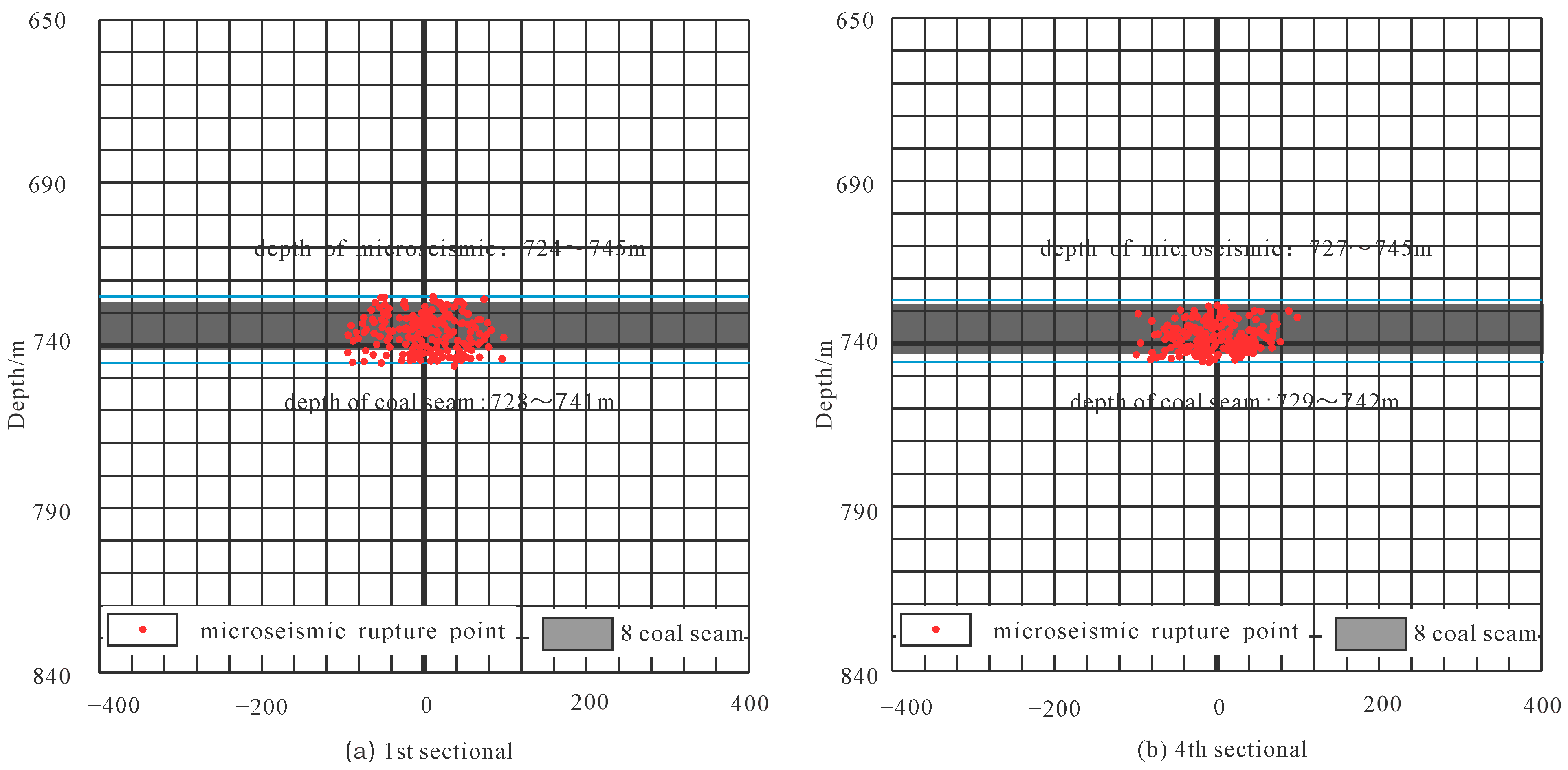
5.2. Luling Coal Mine of Huanbei Mine Area

LG01 well cluster was constructed in Luling coal mine, Anhui Province, China [32]. The horizontal well was adjacent to the No. 8 coal seam, which was beneficial for creating transverse fractures during fracturing. The horizontal section length of the LG01-H well was 582 m. Hydraulic fracturing was conducted in seven stages while considering the distribution characteristics of the flat well section, the cementing quality. Perforation and isolation were efficiently implemented using the combined perforation and bridge plug technology, and a total of 6627 m3 of fracturing fluid and 542 m3 of quartz sand were injected in seven stages. The spacing between each stage was between 70 m and 90 m. The maximum injection displacement was 10 m3/min. The maximum construction pump pressure was 27 MPa. The average sand volume was 77 m3 per stage, and the average fracturing fluid injection was 947 m3 per stage. The fracturing construction parameters are shown in Table 6. The microseismic monitoring technology was used during the fracturing construction to monitor the fracture shape.
The total length of central fractures in the first stage was 169.1 m, averaging 84.6 m per wing. The total fracture length in the fourth stage was 163.2 m, averaging 81.6 m per wing, as shown in Figure 18. Both fractures extended slightly more towards the east flank. The height of the primary fractures in the first stage was 20.5 m. The height of the main fractures in the second stage was 17.6 m, and the shape of the prominent fractures in both stages was vertical, as shown in Figure 19. The monitoring results of the microseismic fracture length are shown in Table 7. The roof fractures can cross over into the coal and extend for a long distance. The fracturing with specific conductivity communicates the coal seam with the horizontal wellbore and transforms the reservoir.
The LG01 horizontal well group started to discharge and produce on 19 January 2015. The daily coalbed methane production was stable at more than 10,000 m3 for 92 consecutive days, and the average daily coalbed methane production was 7075 m3 for 512 straight days. The cumulative coalbed methane production of the single well was 590 × 104 m3, with considerable safety and economic benefits (Figure 20). It also created the record for the highest daily coalbed methane production in China’s broken and soft coal seam with weak permeability.
Fang Liangcai predicted the effect of the LG01 horizontal well extraction over a period of five years. The average gas content within the control range of the horizontal well can be reduced to 4.2 cubic meters per ton, which was a decrease of 4.3 cubic meters per ton, 50.6% compared to the initial value of 8.5 cubic meters per ton. This meets the safety requirement of gas content in the Huabei mining roadway being less than 6 cubic meters per ton. Additionally, the average reservoir pressure can be reduced to 2.30 MPa, which represents a decrease of 66.2%. Therefore, it can be concluded that the horizontal well extraction of coal seam gas can significantly reduce gas content and reservoir pressure [33].

5.3. Comparative Analysis

The geological coal conditions in the Huainan and Huaibei coal mines are basically the same, both belonging to the traditionally defined fractured, soft, low-permeability, and gas-prone coal seams. Due to the difficulty of drilling holes in coal seams, both mines have adopted the development method of horizontal well segmentation fracturing. In direct tests, the gas production effect in the Huaibei coalfield was significantly better than that in the Huainan coalfield.
(1)
The main reasons for this difference lie in the geological conditions. The coal seam thickness in the Luling parameter well of Huaibei coalfield was 13.50 m, belonging to the stable ultra-thick coal seam in the entire region. In contrast, the coal seam thickness in Huainan coal mine was only 6.70 m, with significant variations in coal thickness.
(2)
Furthermore, based on the statistical data of the gas storage ratio from the parameter wells, the average gas storage ratio in the Panxie coal mine of Huainan was only around 0.55, while the average gas storage ratio in the Luling coal mine of Huaibei was around 0.64, reflecting the relatively low gas saturation of coal seams in the Huainan coalfield. From the permeability data of coal seams in the Huainan coalfield, it can be observed that the permeability of coal seams was low, with a maximum measured permeability of only 0.011 md, indicating extremely poor permeability of coal seams. Although the permeability of the No. 8 coal seam in Luling coal mine was also low, ranging from 0.18 to 0.99 md, it was much higher than that of the Panxie coal mine in Huainan.
(3)
Finally, due to the shallower burial depth, the bottom depth of Luling coal mine in Huaibei was approximately 742 m, while the burial depth of Panxie coal mine in Huainan was deeper, averaging around 1100 m. This resulted in increased pumping pressure for fracturing operations in Huainan, making it difficult to increase the displacement. The displacement in Luling coal mine in Huaibei generally exceed 10 m3/min, while the average displacement in Panxie coal mine in Huainan was around 8.2 m3/min.

6. Conclusions

The study’s findings are listed below:
(1)
The numerical simulation method simulated the penetration and extension law of fracture at the boundary of coal-rock after fracturing in the roof stratum. It was proven that the fracture in the roof stratum can extend to the coal seam. The fracture within the coal can spread rapidly and the fracture width of the coal seam was wider than that of the roof stratum.
(2)
With the increase in the false mudstone roof thickness and under the condition of constant fracturing volume, the width of fractures in the coal seam decreased. The reason was that the fracturing process consumed certain kinetic energy in the fracture of the mudstone pseudo roof, leading to a reduction in pore pressure when the fractures extended into the coal seam, and consequently, a decrease in fracture width. The width of fractures in the coal seam roof initially increased rapidly and then slowed down, with the final fracturing width showing a negative correlation with the thickness of the false mudstone roof. The reason was that the initiation time of the fracture at the interface between the immediate roof and the pseudo roof (sandstone-mudstone interface) increased during the fracturing process, resulting in initially larger widths of roof fractures. After the fracture of the mudstone pseudo roof, the energy loss caused a rapid decrease in the growth rate of fracture width in the later stage.
(3)
Considering the development of the false roof in the mudstone, physical similarity simulation was employed to simulate the expansion fracture. The results indicated that with horizontal boreholes placed within the sandy mudstone of the fractured soft coal seam roof, under reasonable vertical distance and high-volume fracturing fluid construction, and if the coal seam had a relatively thin false roof of mudstone, the fracture can penetrate through the direct roof-false roof interface (sandy mudstone-mudstone interface) and the false roof-coal seam interface (mudstone-coal seam interface), extending into the underlying coal seam. The fracture then extended to form a curved and irregular stepped pattern, demonstrating that hydraulic fracturing can achieve the goal of fracturing and increasing production in both soft and hard coal seams. However, when the coal seam developed a thicker false roof of mudstone, the mudstone created a blocking effect on hydraulic fracturing, making it difficult for the fracture to open the underlying coal seam. It was evident that the thick false mudstone roof was a detrimental factor for hydraulic fracturing and production enhancement of the coal seam roof. Therefore, it is recommended to increase the construction volume in areas where the false mudstone roof is well developed.
(4)
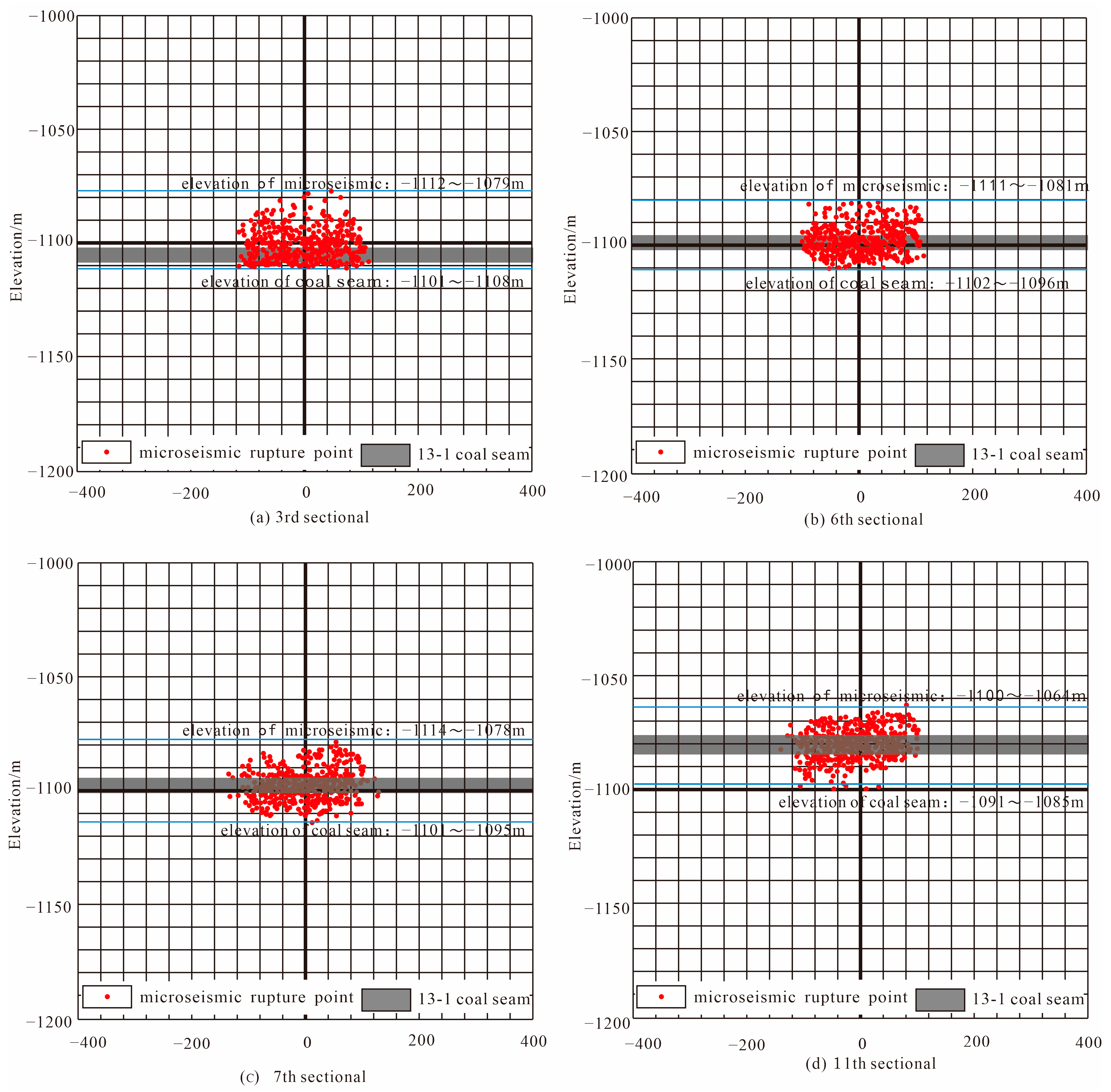
The engineering verification conducted at the Panxie coal mine and the Luling coal mine showed that by utilizing a construction drainage rate of 7.5 cubic meters per minute at Panxie coal mine, the maximum fracture length reached 218.3 m, with a maximum fracture height of 36.8 m. The maximum daily gas production of a single well reached 1450 cubic meters per day, with a total gas extraction volume of 43.62 × 10⁴ cubic meters over two years. At Luling coal mine, utilizing a construction drainage rate of 10 cubic meters per minute, the maximum fracture length reached 169.1 m, with a maximum fracture height of 20.5 m. The maximum daily gas production of a single well reached 10,775 cubic meters per day, with a total gas extraction volume of 590 × 104 cubic meters for 1090 days. This indicated that the fracture within the roof can penetrate the composite roof of coal seams and extended to the interior of the coal seams, achieving the purpose of transforming fractured and low-permeability coal seams and providing an effective mode of gas extraction.

Author Contributions

Methodology, B.W. and Q.L.; Software, B.W., Z.L., T.F. and Y.G.; Validation, B.W. and Z.L.; Formal analysis, E.H. and W.D.; Investigation, T.F. and B.M.; Data curation, B.W., L.M. and Z.G.; Writing—original draft, B.W.; Writing—review & editing, B.W.; Visualization, L.M.; Supervision, E.H.; Project administration, B.W. and L.M.; Funding acquisition, E.H. All authors have read and agreed to the published version of the manuscript.

Funding

This work was supported by National Natural Science Foundation of China (Program No: 42374176). Natural Science Basic Research Program of Shaanxi(Program No: 2024JC-YBQN-0272). Natural Science Basic Research Program of Shaanxi (Program No: 2022JM-159).

Data Availability Statement

All data generated or analyzed during this study are included in this published article.

Acknowledgments

The authors acknowledge the support provided by Xi’an University of Science and Technology for providing basic facilities to compile this work.

Conflicts of Interest

Authors Bo Wang, Liang Ma, Zaibin Liu, Tao Fan, Zewen Gong, Yaoquan Gao, Wengang Du, Qiang Liu and Bingzhen Ma were employed by the company CCTEG Xi’an Research Institute (Group) Co., Ltd. The remaining authors declare that the research was conducted in the absence of any commercial or financial relationships that could be construed as a potential conflict of interest.

References

  1. Zhang, W.; Cui, C.; Zhang, Z.; Wei, M.; Ma, X. Optimization of Gas Drainage Parameters for Large-Diameter Drilling in Low-Permeability Coal Seam. Coal Technol. 2024, 43, 195–199. [Google Scholar] [CrossRef]
  2. Chen, B.; Yuan, L.; Xue, S.; Jiang, W.; Yang, K.; Zhou, T.; Li, D.; Wu, J. Study on segmented fracturing and horizontal well drainage technology for coal seam roof in Huainan mining area. Coal Sci. Technol. 2024, 1–11. Available online: http://kns.cnki.net/kcms/detail/11.2402.td.20240327.1504.003.html (accessed on 18 April 2024).
  3. Wang, E.; Zhang, G.; Zhang, C.; Li, Z. Preventionand control of coal and gas outburst in China Progress and prospect of theoretical and technical research. J. Coal 2022, 47, 297–322. [Google Scholar]
  4. Ding, Y.; Zhu, B.; Li, S.; Lin, H.; Wei, Z.; Li, L.; Long, H.; Yi, Y. Accurate identification and efficient extraction of pressure relief gas in goaf of high outburst mines. J. Coal Ind. 2021, 46, 3565–3577. [Google Scholar]
  5. Chai, J.; Liu, Y.; Wang, Z.; Lei, W.; Zhang, D.; Ouyang, Y.; Sun, K.; Weng, M.; Zhang, Y.; Ding, G.; et al. Pressure relief effect and optical fiber monitoring of coal and rock underlying protected layer mining. J. Coal Sci. 2022, 47, 2896–2906. [Google Scholar]
  6. Wu, D.; Li, S. Research on regional gas drainage technology using holes instead of roadways in a single medium thick coal seam. Coal Technol. 2021, 40, 58–62. [Google Scholar]
  7. Li, Q.; Ye, S.; Jin, X. Application of hole protection technology and equipment for bedding hole screen tubes in soft coal seams. Coal Sci. Technol. 2017, 45, 147–151. [Google Scholar]
  8. Tang, Y.; Li, P.; Zhu, G.; Chen, J.; Chen, D.; Feng, A.; Tang, Z.; Yang, Y.; Ye, M. Application of ultra-high pressure hydraulic cutting technology in medium hardness and low permeability coal seams. Coal Sci. Technol. 2022, 50, 43–49. [Google Scholar]
  9. Zhou, L.; Peng, Y.; Lu, Y.; Xia, B. Numerical simulation study on hydraulic slotting, pressure relief, desorption, and permeability enhancement of deep coalbed methane based on the material point method. J. Coal Sci. 2022, 47, 3298–3309. [Google Scholar]
  10. Liu, W.; Xu, X.; Han, J.; Wang, B.; Li, Z.; Yan, Y. Trend model and key technologies for methane emission reduction in coal mines under carbon neutrality goals. J. China Coal Soc. 2022, 47, 470–479. [Google Scholar] [CrossRef]
  11. Li, S.; Zhang, J.; Lin, H.; Ding, Y.; Bai, Y.; Zhou, Y.; Zhu, B.; Dai, Z. Reflections on the development path of coalbed methane co-production technology in the dual carbon strategy. Coal Sci. Technol. 2024, 52, 138–153. [Google Scholar]
  12. Jia, J.; Chen, C.; Dong, K.; Wu, Y.; Wu, M. Research on staged fracturing and efficient extraction of coalbed methane from horizontal wells in fractured soft and low-permeability coal seams. Nat. Gas Geosci. 2017, 28, 1873–1881. [Google Scholar]
  13. Zhang, Q.; Jiang, W.; Jiang, Z.; Sun, S.; Li, B.; Du, X.; Wu, X.; Zhao, J.; Fan, Y.; Fan, Z.; et al. Current status and technological research progress of coalbed methane surface development in China’s coal mining areas. Coal Geol. Explor. 2023, 51, 139–158. [Google Scholar]
  14. Xu, Y.; Zhang, P.; Fan, Z.; Xu, J.; Zhu, W.; Wang, J. Analysis of layer fracturing and crack propagation laws and sensitive factors of horizontal well drilling in crushed soft coal seam roof. J. Min. Saf. Eng. 2023, 40, 420–428. [Google Scholar] [CrossRef]
  15. Wu, X. Research on the Law and Mechanism of Fracture Propagation in Horizontal Well Staged Fracturing in Fractured Soft and Low-Permeability Coal Seam Roof. Ph.D. Thesis, General Institute of Coal Science Research, Beijing, China, 2017. [Google Scholar]
  16. Jiang, Z.; Li, H.; Xu, Y.; Zhang, Q.; Li, G.; Fan, Y.; Jiang, W.; Shu, J.; Pang, T.; Cheng, B. Geological adaptability analysis and construction parameter optimization of segmented fracturing horizontal wells in coal seam roof. Coal Geol. Explor. 2022, 50, 183–192. [Google Scholar]
  17. Zhang, Q.; Ge, C.; Li, W.; Jiang, Z.; Chen, J.; Li, B.; Wu, J.; Wu, X.; Liu, J. High efficiency extraction model of fractured coalbed methane from horizontal wells in fractured soft and low-permeability coal seams. J. Coal Ind. 2018, 43, 150–159. [Google Scholar]
  18. Xu, C. Study on the Controlling Effect of Geological Structure on Coal Seam Gas Occurrence and Prevention and Control Technology in the Huaibei Mining Area. Ph.D. Thesis, China University of Mining & Technology, Beijing, China, 2023. [Google Scholar]
  19. Hu, Q.; Liu, J.; Li, Q.; Zhang, Y.; Song, M.; Sun, W.; Song, J. Experimental study on stress and crack evolution of segmented hydraulic fracturing in coal seam roof. J. China Univ. Min. Technol. 2023, 52, 1084–1095+1202. [Google Scholar] [CrossRef]
  20. Pang, T.; Jiang, Z.; Yang, J. The influence of the spatial location of horizontal wells in the roof of fractured soft coal seams on the expansion of fracturing fractures. J. Coal Sci. 2022, 47, 196–203. [Google Scholar]
  21. Jiang, Z.; Li, H.; Fang, L.; Fan, Z. Fracture extension machine for horizontal wells adjacent to the roof of fractured soft coal seams. J. Coal Ind. 2020, 45, 922–931. [Google Scholar]
  22. Li, Q.; Deng, Y.; Hu, Q.; Wu, X.; Wang, X.; Jiang, Z.; Liu, Y.; Qian, Y.; Song, M. Overview and prospect of physical test research on hydraulic fracturing of coal and rock. Coal Sci. Technol. 2022, 50, 62–72. [Google Scholar]
  23. Xu, Y.; Guo, S. Staged fracturing technology and application of coalbed methane horizontal wells combined with soft and hard coal. J. Coal Ind. 2019, 44, 1169–1177. [Google Scholar]
  24. Zhu, Q.; Yang, Y.; Wang, Y.; Shao, G. Optimization model and application of efficient development engineering technology for high-rank coalbed methane. Nat. Gas Ind. 2017, 37, 27–34. [Google Scholar]
  25. DB/T 14-2018; Specification of Hydraulic Fracturing and Overcoring Method for In-Situ Stress Measurement. The China Earthquake Administration: Beijing, China, 2018.
  26. Xu, Y.; Zhu, Y.; Zhang, P. Technology for developing coalbed methane in horizontal wells in roof strataadjacent to fractured and soft coal seams. Nat. Gas Ind. 2018, 38, 70–75. [Google Scholar]
  27. Li, W.; Bai, J.; Cheng, J.; Peng, S.; Liu, H. Determination of coal-rock interface strength by laboratory direct shear-tests under constantnormal load. Int. J. Rock Mech. Min. Sci. 2015, 77, 60–67. [Google Scholar] [CrossRef]
  28. Zou, J.; Chen, W.; Yuan, J.; Yang, D.; Yang, J. 3-D numerical simulation of hydraulic fracturing in a CBM reservoir. J. Nat. Gas Sci. Eng. 2017, 37, 386–396. [Google Scholar] [CrossRef]
  29. Juan, G. Geo-Stress Condition of Coalbed Methane Extraction in Coalmining Area and Its Influence on Productivity of Coalbed Methane Wells. Ph.D. Thesis, China University of Mining & Technology, Beijing, China, 2016. [Google Scholar]
  30. Hou, B.; Chang, Z.; Wu, A.; Elsworth, D. Simulation of competitive propagation of multi-fractures on shale oil reservoir multi-clustered fracturing in Jimsar sag. Acta Pet. Sin. 2022, 43, 75–90. [Google Scholar]
  31. Chang, Z.; Hou, B.; Ding, J. Competitive propagation simulation of multi-clustered fracturing in a cracked shale oil reservoir. Geomech. Geophys. Geo-Energy Geo-Resour. 2022, 8, 1–19. [Google Scholar] [CrossRef]
  32. Lau, H.C.; Li, H.; Huang, S. Challenges and Opportunities of Coalbed Methane Development in China. Energy Fuels 2017, 31, 4588–4602. [Google Scholar] [CrossRef]
  33. Fang, L.; Li, G.; Li, D.; Li, H.; Liu, J. Analysis of coalbed methane extraction effect of coal seam roof horizontal wells in the Luling Coal Mine, Huaibei. Coal Geol. Explor. 2020, 48, 155–160+169. [Google Scholar]
Figure 1. Distribution map of broken and soft coal seams in China.
Energies 17 01941 g001
Figure 2. Mode of roof rock in sectional hydraulic and horizontal well fracturing.
Energies 17 01941 g002
Figure 3. Schematic diagram of numerical simulation model for fracturing and fracture perforation.
Energies 17 01941 g003
Figure 4. Expansion diagram of fracturing fractures in the coal seam roof.
Energies 17 01941 g004
Figure 5. Comparison chart of fractures in overlying strata and the coal seam.
Energies 17 01941 g005
Figure 6. Statistical chart of the fracture width of the coal seam roof.
Energies 17 01941 g006
Figure 7. Statistical chart of fracture width of coal seam.
Energies 17 01941 g007
Figure 8. Fracture width under different pseudo roof thickness conditions.
Energies 17 01941 g008
Figure 9. Pore pressure under different pseudo roof thickness conditions.
Energies 17 01941 g009
Figure 10. Hydraulic fracturing physical simulation model, (a) schematic diagram of physical simulation, (b) physical simulation model image.
Energies 17 01941 g010
Figure 11. Physical simulation results of hydraulic fracturing for 1# piece.
Energies 17 01941 g011
Figure 12. Schematic diagram of fracture interpretation for acoustic emission monitoring of 1# piece.
Energies 17 01941 g012
Figure 13. Physical simulation results of hydraulic fracturing for 2# piece.
Energies 17 01941 g013
Figure 14. Schematic diagram of fracture interpretation for acoustic emission monitoring of 2#.
Energies 17 01941 g014
Figure 15. Fracture orientation and length of XX-1L well.
Energies 17 01941 g015
Figure 16. Profile of microseismic monitoring for fractures in XX-1L well.
Energies 17 01941 g016
Figure 17. Drainage and production curve of the XX-1L well group in Panxie coal mine.
Energies 17 01941 g017
Figure 18. Fracture orientation and length of LG01 well.
Energies 17 01941 g018
Figure 19. Profile of microseismic monitoring for fractures in LG01 well.
Energies 17 01941 g019
Figure 20. Drainage and production curve of the LG01 well group in the Luling coal mine.
Energies 17 01941 g020
Table 1. Coal Seam and Surrounding Rock Parameters Table.
Rock NameDepth/mThickness/mPermeability/mDGas Content/m3·t−1
Panxie Coal Mine
(Huainan mine area)
Siltstone1100.304.000.015\
Mudstone1101.301.000.003\
13-1 Coal seam1108.006.700.01115.28
Luling Coal Mine
(Huaibei mine area)
Siltstone727.753.200.015\
Mudstone728.500.550.005\
8 Coal seam742.0013.500.3608.50
Table 2. Rock mechanics parameter settings of the roof fracturing model.
RockFine-Grained SandstoneSiltstoneMudstoneCoal SeamMudstone
Elastic modulus/GPa20.0015.5011.805.1011.80
Poisson’s ratio0.230.250.280.330.28
Tensile strength/MPa4.502.421.750.501.75
Density/(kg·m3)2.542.051.851.351.85
Permeability/10−3 μm22 × 10−310−210−310−210−3
Vertical stress/MPa17.7417.7417.7417.7417.74
Stress of Maximum horizontal principal/MPa16.3016.3016.3016.3016.30
Stress of Minimum horizontal principal/MPa14.0013.5013.0010.0014.00
Table 3. Physical rock parameters of test specimens.
Physical Rock Parameters of Test SpecimensImmediate RoofMudstone Pseudo-RoofCoal Seam
1# Piece2# Piece1# Piece2# Piece1# Piece2# Piece
Elastic Modulus/GPa17.9018.4015.0015.501.001.10
Poisson’s Ratio0.200.200.200.180.280.25
Tensile Strength/MPa3.503.502.202.100.500.50
Table 4. Statistical table of fracturing construction parameters for XX-1L horizontal well.
Section SequenceHydraulic Fracturing
Liquid Volume/m3
Sand Total/m3Average Pump Pressure/MPaAverage Sand Ratio/%Average Displacement/m3·min−1
1113135.022.46.77.3
2100145.133.48.28.2
396745.539.38.48.0
4101155.244.79.25.7
598560.947.610.47.1
662531.229.110.57.4
760125.934.58.47.0
8102840.833.87.37.7
9118146.734.26.98.0
1090247.333.08.18.0
11105979.330.411.67.8
1250421.725.47.28.0
Table 5. Statistical table of microseismic monitoring for fracture lengths in XX-1L horizontal well.
Section SequenceOrientation/°Total Fracture Length/mEast Wing Fracture Length/mWest Wing Fracture Length/mHeight/mInclination Angle/°
371.7205.1112.292.931.53
674.9197.7108.289.530.05
780.6191.592.998.636.83
1177.9218.3104.8113.536.81
Table 6. Statistical table of fracturing construction parameters for LG01-H horizontal well.
Section SequenceHydraulic Fracturing
Liquid Volume/m3
Sand Total/m3Average Pump Pressure/MPaAverage Sand Ratio/%Average Displacement/m3·min−1
197963.830.99.2710.0
297665.524.49.7710.0
392778.822.913.1910.0
492080.021.813.379.50
5101986.926.712.4810.0
697283.422.412.6610.0
783482.920.815.489.60
Table 7. Statistical table of microseismic monitoring for fracture lengths in LG01-H horizontal well.
Section SequenceOrientation/°Total Fracture Length/mEast Wing Fracture Length/mWest Wing Fracture Length/mHeight/mInclination Angle/°
145.2169.190.578.620.52
446.1163.289.873.417.63
Disclaimer/Publisher’s Note: The statements, opinions and data contained in all publications are solely those of the individual author(s) and contributor(s) and not of MDPI and/or the editor(s). MDPI and/or the editor(s) disclaim responsibility for any injury to people or property resulting from any ideas, methods, instructions or products referred to in the content.

