
Innovative Approach of Concentrated Solar Sphere to Generate Electrical Power


Mechanical Engineering Division, Sharjah Men’s College, Higher Colleges of Technology, Sharjah P.O. Box 7946, United Arab Emirates
Energies 2024, 17(8), 1956; https://doi.org/10.3390/en17081956
Submission received: 9 March 2024
/
Revised: 11 April 2024
/
Accepted: 15 April 2024
/
Published: 19 April 2024
(This article belongs to the Section B: Energy and Environment)
Abstract
:Energy sources are crucial for the development and growth of economies and civilizations. Solar energy is an alternative energy to generate electrical power. The challenges of solar photovoltaic panels (PV) are the low output power and efficiency and the huge installation area beside PVs need a tracking system for better efficiency. The motivation of this paper is to design an innovative solar sphere system, which is a new concentrated photovoltaic technology that has better performance (efficiency and output power) than the normal conventional solar panel (PV) with a smaller installation area and without any tracking system. This design consists of an acrylic solar sphere entirely filled with cooking oil (sunflower or corn oil) that captures solar radiation and concentrates it on a focal point. The focal point is adjusted over a multi-junction cell that acts as a collector device (concentrator solar cell). This focused solar energy can generate a massive amount of power, which is used to produce more electricity than normal photovoltaic panels. The experiments were carried out in order to discover the best acrylic models or shape designs, which is the sphere, the best materials or media in the sphere, that is oil, the best sphere’s size and volume, and that is larger, the best sphere thickness, which at first is lower, the best fluid oil type, which is cooking oil, and finally the best fluid amount or volume inside the sphere, and this is the entire volume. Then, these factors mentioned above are compared with normal photovoltaics (PV) that have the same section area as these shapes. The results revealed that these factors have significant effects on the output power value and efficiency. It has been demonstrated that our innovative concentrated solar sphere system can produce nearly four times the output power or electricity greater than that of a conventional solar panel PV with the same cross-sectional area. This specific sort of compression is crucial because it shows that less space is required to establish this system than it would to install conventional solar panels. The performance of the system per unit of the square area it occupies was compared to the latest generation of flat panel PV available at the market performance; hence, the installation space will be decreased by 40% to 60%. Our system has about twice as much efficiency as solar PV and does not require a tracking system and maintenance. Our technology also has the benefit of not being impacted by extreme temperatures, clouds, dust, and humidity.
Keywords:
renewable; energy; concentrated; solar; multi-junction; photovoltaic cells; solar power; sphere1. Introduction
The need for various energy sources with regard to future energy supply, environmental impact, and energy conservation is the most urgent and important issue that many countries and organizations have been looking for recently. Energy sources are crucial for the development and growth of economies and civilizations. The problems of energy and climate change have finally ended up where they belong at the heart of public attention. At the time, numerous experts were already calling for a speedy restructuring of the entire energy supply. As countries and rural (village) communities become more developed or get richer there is a greater demand for energy because people get more materialistic and buy more products that use energy both in their manufacture as well as in their use [1,2]. On the other hand, energy and the environment have a strong relationship. The production and consumption of energy are some of the biggest causes of the world’s current environmental problems on Earth and pose many problems for sustainable development [3,4,5]. Furthermore, oil production supply will grow at a slower rate compared to demand, causing an energy crisis after the peak point due to expanded shortage, which will disturb and destabilize economies, and this will lead to a rapid decline in production due to collapsed industries [6,7,8,9]. Electricity is extremely crucial in everyday life. Fuels are becoming scarce these days. As a consequence, there is a need to consider alternative energy sources, hence, renewable energy sources (RES) are the greatest available solution and an alternative source of generating electricity [10]. Renewable energy could completely cover all our energy supply needs within a few decades. This is the only way to end our dependence on energy sources like oil and uranium, which are so costly both in financial terms and in the havoc they wreak on our environment. Hence, renewable energy can satisfy our hunger for energy in a way that is sustainable and compatible with the climate. As a result, extensive research on how to use renewable energy supplies efficiently has been published. Solar energy is one of the most significant renewable energy resources that can make substantial contributions to future energy generation because it is a clean energy source that can contribute to enormous amounts of energy output [11,12,13]. Solar energy, which has a wide range of uses, has been utilized for water heating, direct photovoltaic power generation, thermal applications and generating electricity via the thermal route, and steam generation utilizing parabolic trough solar collectors [14,15,16]. It is believed that the Earth receives around 1000 W/m2 of solar irradiation every day [17]. Abbot [18] showed that this quantity of irradiation could create around 8500 TW globally and concluded that solar energy alone has the potential to fulfill the present energy demand [19]. Photovoltaic technology is inexpensive, requires minimal upkeep, and emits no pollution. This technology is dependable and has no moving components [20,21]. Solar cells, which are a major source of energy extraction, have extremely attractive properties and may be utilized as a primary source that can be connected to grids. As a result, the system must operate at maximum capacity. Numerous MPPT approaches are employed to retain maximum power throughout the operation. These MPPT approaches are critical components of PV systems because they assist in increasing efficiency [22]. Ref. [23]’s research endeavor devised and built a system for collecting solar energy at high temperatures for medium and high-temperature applications. The system, constructed at Algiers’ renewable energy development center, comprises a 2 m = 60° included angle, R0 = 0.90 m diameter spherical reflector with a cylindrical receiver filled with water, tracking reflector that moves into focus with the sun’s movement. The device is capable of heating water or other fluids to temperatures beyond 350 °C, allowing for the production of process heat for home use as well as the storage of solar energy compactly and cost-effectively. The optical parameters of the system were analyzed to help in the construction of the spherical reflector and cylindrical receiver [23].
The solar sphere is a new idea that gives a higher efficiency than the normal solar panel collector. It has more advantages compared with the normal flat panel as follows: First—the solar panels should always face the sun. In the northern hemisphere, for example, solar panels should always face true south. Second—the sun angles in the sky vary according to the location, time of the day, year, or seasons. Hence, the inclination of the panel can only be made optimal at certain times during the year. This leads to the use of the sun-tracking system. The sun-tracking technology is too costly, impractical, and unworkable for most solar collectors, and some cannot even alter their orientations manually or there are difficulties in adjusting the inclinations manually. Third—these panels occupy a large place for ideal installation that may not be available even if they can face the right direction. Fourth—nearby higher buildings or larger structures may block the sun rays from some directions. [3,24,25]. A German architect called Andre Broessel was inspired by his daughter’s toy marbles to design a solar sphere that can concentrate and diffuse direct light on a solar panel that tracks the movement of the sun. He was a finalist in the World Technology Network Award 2013. His design, named the Rawlemon design, uses a high-efficiency multi-junction cell [4,26]. The “beta. ray” is the name given to Rawlemon’s prototype spherical sun power generator. This generator used spherical geometry concepts in conjunction with a dual-axis sun-tracking device. The glass sphere/ball lens focuses and disperses scattered sunlight onto a small area (single focal point) of tiny solar panels, resulting in less material utilized to build solar cells and higher efficiency. The “beta. ray” is a spin on concentrated photovoltaic (CPV) technology, which employs numerous optical components, such as mirrors and lenses, to focus light into a super-concentrated beam targeted at a solar cell. The “beta. ray” features a surface of small solar panels, also known as the collector, that is positioned on a dual-axis tracking system that travels with the sun to always face the sun perpendicularly [27]. It does this to enhance the effectiveness of the sun’s beams in conversion. The spherical sun power generator may double the output of a typical solar panel in a considerably smaller surface area by continually rotating the collector to optimum efficiency [26,28]. Broessel believes this glass sphere could be the future of solar energy. Another trial was conducted by Kuo-Chi Lin et al. [19], where their research proposes a unique solar collecting method in which solar cells are printed directly onto a spherical surface, such as a balloon. Besides the efficiency consideration, the balloons coated with PV solar collectors have other features that make them attractive. For example, it is light and portable, it is easier to be taken in bad weather, and it can be decorated and make a beautiful scene [29]. There are various initiatives now underway to install solar concentrators. These initiatives were undertaken by research institutes, universities, and businesses to create and assess the dependability and performance of solar concentrators. Recent research on the next generation of solar cells has resulted in the usage of a broad sunlight spectrum for increased efficiency. A multi-junction solar cell (MJSC) is a stack of several types of photovoltaic junctions connected via homojunction, intrinsic materials, or tunnel junctions. To successfully catch and convert a wide variety of photon wavelengths into usable electrical power, multiple solar cells with varying bandgap energies and physical features are combined. Currently, MJSCs can generate around twice as much electricity as a conventional solar cell of the same area [30,31,32,33,34,35,36]. They are an appealing alternative because of their great theoretical conversion efficiency compared to other photovoltaic technologies, improved power generation, and low cost [37]. Two types of MJSCs were tested: InGaP-GaAs dual-junction sun cells with InGaP tunneling layers and InGaP-GaAs-Ge triple-junction solar cells with GaAs tunneling layers. According to the research, increasing the number of solar cell layers can result in substantially greater efficiency [36,38,39,40,41,42]. Solar cells have recently surpassed their previous efficiency record of 40.7%, which was achieved with a MJSC by Boeing Spectro Lab Inc. in December 2006 in Washington, DC, USA [43], or such as those from the business Azurspace, attain efficiencies of up to 42.1% [44,45]. When compared to traditional solar cells comprised of a single layer of semiconductor material, using novel technology in the creation of III–V MJ solar cells enables greater efficiencies that approach 43% at high concentrations [46,47]. Now, Solar Junction (San Jose, CA, USA) has announced a new world-record conversion efficiency of 44% for a production-ready solar photovoltaic (PV) cell using its multi-junction technology. They have a low electrical resistivity as well as a strong optical transmissivity [48,49,50,51,52,53,54,55,56]. Triple junction (3J) solar cells have already surpassed 44% efficiency (2013), and 4- to 5-junction solar cells are predicted to achieve 50% efficiency [57]. Some CPVs have reached the greatest efficiency so far at 47.1% [58], with a further improvement to 50% projected in the next years [59]. On a global scale, around 370 MWp of CPV systems are currently deployed and linked to the grid [60,61]. Concentrated photovoltaics (CPV), long a niche technology, has now matured and shown to be reliable enough for large-scale power generation. The employment of high-efficiency triple-junction solar cells with concentrating lenses, particularly in high-temperature settings, provides for steady energy production [57]. When comparing CPV with silicon photovoltaics with the same area or installed power, one of the key benefits of CPV is the possibility of a substantially greater energy supply [57]. The use of optical components to focus sunlight is only practical when very high-efficiency solar cells are used. Thus, research on concentrated photovoltaics, a very ancient notion [62], got a substantial push only when multiple junction solar cells became affordable. Multiple junction solar panels were initially created for satellite powering, first as double junctions and subsequently as triple junctions (today a common technology). Concentrated photovoltaic modules employ 3J solar cells that function well in hot conditions, even when employing passive (air) cooling. Using greater-efficiency solar cells allows a CPV module to produce more power and energy while taking up less space. CPV modules can also be manufactured of recyclable materials, reducing their overall environmental impact [63,64,65,66,67]. Hashem and Abdulrahman [46] carried out an outdoor investigation to assess the amount of effect on the electrical performance of multifunction (MJ) solar cells. In addition, the irradiation uniformity was increased using numerous ways, including extending the distance between the concentrator and the receiver and incorporating a supplementary optical element (SOE) on the receiver. The outside measurement also indicated that the electrical efficiency of the solar cell increased by 68%, from roughly 22% to 37%, due to improved irradiation uniformity. Semiconductor compounds have the best PV conversion efficiency [51,68,69,70,71]. MJ solar cells are built up of a stack of stacked p–n junctions, each made from a distinct set of semiconductors with a different band gap and spectral absorption to catch as much of the sunlight spectrum as possible. Semiconductors such as Ge, GaInAs/GaAs, and GaInP are extensively employed in triple-junction solar cells due to their high optical absorption coefficients and appropriate minority carrier lifetimes and mobilities [71,72,73]. The first layer (GaInP) transforms the short wavelength section of the spectrum, the second layer (GaInAs) collects near-infrared light, and the third layer (Ge) absorbs the lower photon energies of infrared radiation in a triple-junction solar cell. The multi-junction cell setup consists of magnifying lenses, that focus the solar radiations into a focal area in the cell. This focused area is attached to a heat sink. The multi-junction (MJ) solar cells are sunlight-based cells with various p–n intersections made of various semiconductor materials. Every material’s p–n intersection creates an electric current because of various frequencies of light. The utilization of various semiconducting materials permits the absorbance of a more extensive scope of frequencies, improving the cell’s sunlight to electrical energy transformation productivity. Traditional single-junction cells have a maximum theoretical efficiency of 33.16% [74]. Theoretically, an infinite number of junctions have a limiting efficiency of 86.8% under highly concentrated sunlight [75]. Presently, MJMCs are capable of generating twice to four times as much power as conventional solar cells of the same area [32]. The studies show that much higher efficiencies can be achieved by increasing the number of solar cell layers [76].
Acrylic spheres filled with oil have various applications due to their optical and mechanical properties. They can be used as lenses or optical components in various optical devices such as magnifiers, microscopes, and cameras. Moreover, in scientific and industrial applications, they can be used in refractometers to measure the refractive index of liquids. Furthermore, they can act as light diffusers, scattering and diffusing light passing through them. This property makes them useful in lighting fixtures, displays, and signage to create soft, uniform illumination. Also, in engineering applications, acrylic spheres filled with oil can be employed as hydraulic dampers or shock absorbers. When subjected to mechanical force or pressure changes, the oil inside the sphere helps absorb and dissipate the energy, reducing vibrations and impacts. On the other hand, they can serve as calibration standards for various instruments and sensors. Their precise dimensions and known optical properties make them useful for calibrating measurement devices such as spectrophotometers and imaging systems besides education and demonstrations. Overall, acrylic spheres filled with oil offer a versatile combination of optical clarity, mechanical resilience, and customization options, making them valuable in various scientific, industrial, and artistic applications [77,78,79,80,81,82,83,84,85,86,87,88]. The spherical concentrated sun power generator appears to be an excellent idea that may aid in the transition from fossil fuels to completely renewable energy. However, due to a lack of technological development and study, we are still a long way from seeing these solar spheres become a reality. Hence, more information and more details on this topic should be accumulated, and more experiments should be conducted to achieve this kind of application. In this paper, an innovative concentrated solar sphere system is designed, which was found to be a liquid (cooking oil)-filled solar sphere, that can directly convert sunlight into electricity using the multi-junction device under the sphere. The solar sphere collects solar radiation from all directions and then concentrates it on a small focal area of a highly efficient solar cell. This innovative concentrated solar sphere technology is used and tested experimentally to solve many issues and problems that PV faces, such as low power output, efficiency, the effect of dust, humidity, high temperatures, maintenance, and space area for installation. A pyranometer is used to measure the solar irradiance, and a multimeter is used to measure the voltage and the current ampere, hence computing the electrical power out of the system and the efficiency. The state of the art, as well as the benefits and drawbacks of this technology, were demonstrated. The goal of the experiments presented in this paper is to find a better performance (efficiency and output power) than the normal conventional solar panel (PV) with a smaller installation area. Hence, the experimental measurements are conducted for nine shapes and model designs, four sphere thicknesses, four sphere sizes with diversified mediums or materials, and later on with eight fluid oil types and five fluid amounts or volumes during the whole year. The significance of the results shows that our innovative solar sphere design, which is a new concentrated photovoltaic technology, has better performance (efficiency and output power) than the normal conventional solar panel (PV) with a smaller installation area. Hence, these advantages of our tested system confirmed that it is applicable to replace conventional PV. In this paper, the experimental apparatus and design are explained in Section 2, where the genuine outdoor testing setup is clarified, including the function of all elements that are used in this test. Furthermore, the multi-junction cell structure and function are described. In Section 3, the results and calculations are illustrated where nine shapes and models made of acrylic are examined, various materials (solids, liquids, and gases) are tested, the sphere’s size and volume are explored, the effect of the used shape acrylic thicknesses of the sphere are demonstrated, eight types of fluid oil are tried are investigated in order to determine the most effective oil and the effect of fluid oil volume/amount inside the sphere is reviewed. The discussion is stated in Section 4, while the conclusion is shown in Section 5.
2. Experimental Apparatus and Design
An experimental setup is designed as shown in Figure 1. The solar-shaped container/sphere (No. 1) is made of acrylic (Plexiglas), which allows optical access and enables the collection of the solar radiation required to be concentrated. It is filled with fluid mediums or materials such as oil, water, and air in the best materials or media in the sphere in order to find out the best materials or media in the sphere, which will be the oil later. A stainless-steel stand (No. 2) in Figure 1 or a stainless-steel movable table with an adjustable tray is designed to carry the container/sphere. A multi-junction concentrator solar cell (No. 3) is set on the stand (No. 4) under the solar sphere and connected directly with a multimeter (No. 5) to measure the power output by measuring the voltage and the current ampere. A pyranometer is used to measure the solar irradiance, and the measured values were compared with the list provided by the government for better accuracy. An Infrared Temperature Thermometer Gun UT300S (UNI-Trend company, Dongguan, China) is used to measure the sphere temperature and the surface temperature of a multi-junction solar cell to ensure no increase in the system temperature. The outdoor environment temperatures range from 24 °C to 50 °C. Hence, the sphere and the fluid temperatures range from 30 °C to 60 °C.
The multi-junction photovoltaic cell module was shipped from Eagle Tech Manufacturing Inc., Watsonville, CA, USA, which is similar to the one designed by [46]. The solar sphere captures the solar radiation incoming from the sun and concentrates it in a focal point. This focal point lies on top of a multi-junction cell that acts as a collector device. The multi-junction cell consists of a primary optic, secondary optic, multi-junction photovoltaic cell, and improved thermal performance for cooling the system, including aluminum housing, as shown in Figure 2. The multi-junction cell is further divided into sub-cells or junctions where each is responsible for converting different parts of the light into electricity. The first layer is GaInP and it is located in the top sub-cell. GaInAs is used for the middle sub-cell and Ge substrate is the third sub-cell. This device can handle high temperatures and can aid in resistance to radiation exposure; hence, it was chosen to be used in this experiment to capture the concentrated solar energy of the focal point. The characteristics and specifications of this multi-junction concentrator solar cell are listed as follows: The dimensions of the whole cell device are 9.007 L × 9.007 W × 5.715 H (cm) as per the manufacturer. The dimensions of the cell without the focusing optics are 0.5 × 0.5 cm. The primary optical concentrator is a Fresnel lens with a 20 mm diameter and 8 mm height; hence, the surface area of the spherical dome is 1005.3 mm2. The Fresnel lens is the favored option as it offers various merits compared to other concentrators, considering its small size, lightweight, ability to be produced in mass quantities at relatively cheap cost efficiency, and enhanced energy density. The secondary optical is a prism with dimensions of 5 × 5 mm on the bottom side over the cell and 15 × 15 mm on the top side directly under the primary optical Fresnel lens, and the height of this optical is 35 mm. A passive cooling system is also provided to the cell, which is the heat sink. The heat sink is made of a ceramic substrate with high thermal conductivity and electrical isolation Rhino (2016) [89]. The passive heat sinks used in multi-junction (MJ) solar cells are designed to dissipate heat efficiently to maintain optimal operating temperatures for the solar cells and to keep the cells within their operating temperature range for optimal performance and longevity. The heat sink typically consists of eleven fins or extended heat dissipation surfaces that increase the surface area for heat dissipation, as shown in Figure 2. These passive heat sinks rely on natural convection, where air circulates around the fins due to buoyancy forces caused by temperature differences. The fins are made of aluminum, which is a thermally conductive material. Each fine with dimensions of 3 × 9 × 0.1 cm. The geometry, thickness of the fins, and spacing between them are carefully designed and optimized to maximize heat transfer and enhance natural convection while ensuring structural integrity with thinner fins and closer spacing to increase the heat transfer coefficient and also increase air resistance hence airflow and pressure drop. The orientation and arrangement of the fins can affect the airflow and heat dissipation efficiency. Fins are arranged perpendicular to the direction of airflow to maximize convective heat transfer. The air temperature and airflow rate in the surrounding environment play a significant role in cooling efficiency. Higher air temperatures reduce the temperature gradient between the solar cells and the surrounding air, decreasing the effectiveness of heat dissipation. Similarly, higher airflow rates can enhance heat transfer but may also increase pressure drop and energy consumption. The multimeter instrument is used to measure the electric values, such as voltage, current, and resistance of multi-junction solar cells [90]. Typically, the multimeters with higher resolution were used to measure the output power by measuring the voltage and the current ampere. The used multimeters have an accuracy of ±0.5% of reading for voltage, and the current ampere measurements with a relative error can be up to ±0.5%. Hence, the multimeters have an accuracy of ±0.25% of calculated output power with a relative error of up to ±0.25% of the computed output power. Furthermore, a measurement range is used to be closest to the expected value in order to minimize errors. Moreover, proper handling of the multimeter was confirmed to ensure good contact with the test points and to avoid unnecessary disturbances to get more accurate measurements.
The experiments are conducted for 9 shapes and models that have the same volume, different volumes and sizes, and different fluid materials and mediums to find out the best size, materials, and shape that produces higher electrical power and higher efficiency. The experiments are conducted and repeated all over the year to cover all the circumstances and seasons of the year then the power output and the efficiency are calculated as an average of the year. The experiments are conducted about 20 days per month. The experiments were conducted to find the best models or shapes, the best materials or media in the sphere, the best shape thickness, and later on, the best fluid oil type and the best fluid amount or volume. The principle of this innovative concentrated solar sphere system can be elucidated as follows: The sun’s radiation enters the acrylic sphere from all angles, where it is transformed into the fluid inside the sphere. The fluid and the acrylic sphere focus the solar radiation into a single focal point. This focus point shifts to lie above the optical lens of the multi-junction photovoltaic cell. The multi-junction device concentrates the energy that has been transformed and directly transforms it into electricity. The fluid inside the sphere of a concentrated solar power system, which is oil, plays a crucial role in generating electricity. The focused solar energy in the acrylic sphere is absorbed by the fluid. The fluid that allows for energy storage also supports and enhances this focused solar energy to be more focused and appropriate for the multi-junction device’s optical lens to receive, enabling electricity generation even when sunlight is not strong, such as during cloudy days. The choice of fluid affects the efficiency of the system as will be explained in a later section. It should be selected with the ability to store and transfer heat effectively. The fluid must be stable at high temperatures and non-corrosive to ensure the safety and longevity of the system. Overall, the fluid inside the sphere of a concentrated solar power system is crucial for capturing, storing, and efficiently converting solar energy into electricity through the multi-junction device, making it a key component of this renewable energy technology.
3. Results and Calculations
In order to calculate the power output of the solar cell (w), the following equations are used.
The output power is
where I and V are the current and the voltage, respectively, which are measured by the multimeter. Then, the current voltage characteristics are plotted to find out the maximum power output.
Pout = I × V
The maximum efficiency is
where Pmax out is the maximum power output. Es is the incident radiation flux that could better be described as the amount of sunlight that hits the Earth’s surface in W/m2. The assumed incident radiation flux under standard test conditions (STCs) that manufacturers use is 1000 W/m2. Keep in mind, though, that STCs include several assumptions and depend on the geographic location. Ac is the area of the collector or the solar cell.
In concentrated photovoltaic systems, the power produced is higher than that of conventional photovoltaic solar panels (PV). The solar collector focuses more sunlight on the receiver, which is the solar cell in our system. To get an overview of how much the solar radiation is concentrated and to get the power input of the solar shapes, some parameters are defined to be used in the following equations:
The geometrical concentration ratio is the amount of solar radiation incident on the receiver and it is obtained from the area of the collector and the receiver. Therefore, the ratio between the areas of the collector and the receiver is called the geometrical concentration ratio (CR) [91,92,93].
The optical concentration ratio is the ratio between light intensities at the collector to the receiver. The optical concentration ratio is less than the geometrical concentration ratio because it includes the losses that are due to light intensities (solar radiation). For concentration technologies, the higher the concentration ratio is, the preferable the system is.
The solar radiation on the receiver, which is the multi-junction solar cell in our system, is
where G is the solar radiation (W/m2), and Pin is the input power of the solar cell
Gr = G × CR (W/m2)
Pin = Gr × Ac
Electrical efficiency:
3.1. Models and Shapes
In order to figure out the best container shape for generating electrical power, nine shapes and models are made of acrylic and are examined. The shapes are as follows: a full sphere, an upper semi-sphere, a bottom semi-sphere, a cylinder in a horizontal position, a cylinder in a vertical position, a vertical half cylinder, a horizontal half cylinder with an upper flat surface, a horizontal half cylinder with a lower flat surface, and a cube. All these shapes are examined for the four different volumes of 523.33 cm3, 904.32 cm3, 1436.03 cm3, and 14,130.00 cm3. All those shapes are filled with water, alcohol, oil, and air. The power output and the efficiency are calculated for all cases after drawing the current-voltage characteristics for each shape and case and finding the maximum output power. Then, these shapes are compared with normal photovoltaics (PV) that have the same sectional area as these shapes, which is the installation area. Figure 3 shows a sample of the current-voltage characteristics for these nine shape forms of 904.32 cm3 volume, including PV. The maximum current for the full solar sphere is close to 4.1 Amps at short-circuit (zero circuit resistance and zero potential voltage across CPV terminals). Up to 5 V, the current is steady. As the voltage rises, the current decreases until it reaches 0 Amps at around 5.6 V (open circuit). The maximum power point, or V = 5 V, is where the operating point is best. While, for other shapes, the current is lower at the short-circuit, which is defined as zero circuit resistance and zero potential voltage across system terminals. A representative comparison between the power output of the aforementioned forms (which are filled with water and then oil) and a standard PV with an equivalent diameter of 0.14 m (volume = 0.01508 m3) is shown in Figure 4 below.
For those various shapes and forms, the trials and the experiments are repeated. It is evident from the figure and after comparing the designs that the entire sphere, made of the same material, produces a larger power output (electricity) than other forms and conventional PV. It generates twice as much power as semi-sphere electricity and four to five times more than a PV with the same sectional area/installation area. The best shapes with the largest output power are ranked as follows, going from highest to lowest: the entire full sphere, the bottom semi-sphere, the upper semi-sphere, the horizontal half cylinder with a lower flat surface, the horizontal half cylinder with an upper flat surface, the PV, the vertical half cylinder, the vertical cylinder, the horizontal cylinder then the cube shape at the end. Hence, in all the upcoming studies and testing, the entire sphere is utilized.
3.2. Materials and Media
The light (solar radiation) flows through the filled-shaped container/sphere as it enters it. In this instance, the sphere acts as a lens, gathering sun radiation from all angles and focusing it on a focal point. Experimental testing of various materials (solids, liquids, and gases) is done for the same volume. Glass, crystal, and acrylic are examples of solid materials. Oil, water, and alcohol are examples of liquids, and air is a commonly utilized gas. The rationale behind the utilization of these fluids and materials or media is to figure out the best media that produces higher output power and efficiency. The goal of testing different materials and fluids is to find the optimal combination that maximizes energy absorption, storage, and conversion efficiency while also considering factors such as cost, availability, and environmental impact. This iterative process helps in advancing concentrated solar sphere system technology and making it more competitive with other forms of renewable energy generation. The specifications for the materials used to fill the sphere are shown in Table 1.
Table 2 illustrates the specifications for acrylic. The sphere to be tested is entirely filled with various mediums and materials, after which the power output and efficiency are determined. As described in the previous section, the experiments are repeated for various quantities in order to obtain more precise results.
Figure 5 compares the power output of the above spheres of different mediums and materials. The results of the experiments indicate that solid materials have the highest power output. These solid materials are undesirable for making electricity because they simultaneously produce a lot of heat and sometimes fire any object or material under them; therefore, those solid mediums are eliminated from testing, especially because they need special care, special devices, and arrangements. Additionally, it was discovered that the power output of the spheres filled with oil is the highest among others, it is 1.3 times more than the sphere filled with alcohol. The sphere filled with alcohol is 1.5 times higher than that of the spheres filled with water. Compared with the other materials, the air-filled spherical produced the least power. The sphere filled with oil produces four to five times more electricity than a PV with the same sectional area/installation area.
To summarize the effect of the shape and the media, another comparison was conducted for the effectiveness of various forms with a volume of 904.32 cm3 for various media and materials to the standard PV that has the same area, as shown in Figure 6. The sphere shape is obviously more efficient than a typical PV. Additionally, among all the materials, the oil sphere has the best efficiency. It has about twice as much efficiency as solar PV.
3.3. Sphere’s Size and Volume
Because the aforementioned experimental results demonstrate that a full sphere made of the same material generates a larger power output than other forms or shapes, four sphere sizes are employed, as shown in Table 3. The power output and efficiency of the spheres with four volumes are then determined.
A comparison of the power output of water-filled spheres of 4 diameters/sizes (10, 12, 14, and 30 cm) is shown in Figure 7. The findings demonstrate that greater output power (power production) is achieved with larger sphere sizes. Furthermore, the power output of the 10 cm diameter sphere is 1.25 times that of the 12 cm diameter sphere, and the power output of the 14 cm diameter sphere is 1.12 times that of the 12 cm diameter sphere, whereas the power output of the 30 cm diameter sphere is twice times that of the 12 cm diameter sphere. It can be predicted that increasing the size by 1 cm diameter ylide increases the power output by approximately 1 watt.
3.4. The Effect of the Shape Thickness
The following acrylic thicknesses of the sphere are used and examined: 3 mm, 4 mm, 6 mm, and 8 mm thicknesses then the power output and the efficiency are calculated. A representative example of the current-voltage characteristics for a solar sphere with a 3 and 6 mm thickness appears in Figure 8. The maximum current for the solar sphere with a 6 mm thickness is close to 10 Amps at short-circuit (zero circuit resistance and zero potential voltage across CPV terminals). Up to 2.5 V, the current is steady. As the voltage rises, the current decreases until it reaches 0 Amps at 2.8 V (open circuit). The maximum power point, or V = 2.5 V, is where the operating point is best. For the 3 mm thick solar sphere, the current is greatest at the short-circuit, which is defined as zero circuit resistance and zero potential voltage across CPV terminals. Nearly 13 Amps of current are produced at short-circuit. Up to 2.5 V, the current is steady. As the voltage rises, the current decreases until it reaches 0 Amps at 2.8 V (open circuit). The maximum power point, or V = 2.5 V, is where the operating point is best.
Figure 9 indicates the relation between the maximum output power for the conventional PV with the same cross-sectional area of our system and the thicknesses of the acrylic solar spheres (3 mm, 4 mm, 6 mm, and 8 mm). Figure 10 compares the efficiency of our technology to conventional PV which has the same cross-sectional area and thicknesses of acrylic solar spheres of 3, 4, 6, and 8 mm.
The numbers above show that the output power of the system increases as the thickness of the acrylic solar sphere decreases. It has been determined that the output power of the 3 mm thick sphere is higher than the 4 mm thick sphere by about 1 w, the 4 mm thick sphere is higher than the 6 mm thick sphere by about 2 w, and the 6 mm thick sphere is higher than the 8 mm thick sphere by about 2 w. Therefore, when the thickness is reduced by 1 mm, the output power rises by around 1 W. Furthermore, it is evident that this system’s output power (the concentrated acrylic solar sphere) is nearly four times greater than that of a conventional solar panel PV with the same cross-sectional area/installation area. This specific sort of compression is crucial because it shows that less space is required to establish this system than it would to install conventional solar panels (PV). It will decrease the installation space by 40% to 60% or less. This percentage is estimated based on the power output and the total area of installation for both our system and the normal conventional solar panels. In theoretical terms, our system requires one-fourth/quarter (1/4) of the installation area that PV requires. In practice, the multi-junction device requires to be moved slightly away from the sphere in the early morning and late afternoon in order to ensure that the focal point hits its lens. In actuality, as the acrylic solar sphere’s thickness increases, the amount of solar radiation that can be absorbed is constrained and decreases. Thus, the output power is decreased. Therefore, the thicker acrylic blocks sunlight and reduces output power. Less thickness results in increased power output and improved efficiency. Hence, the amount of sunlight that is absorbed by the acrylic photons increases with the thickness of the acrylic layer. The higher the output power, the higher the efficiency will be as a result. It is recommended to design the sphere with a thickness of not less than 3 mm to meet manufacturing objectives and safety concerns.
3.5. The Effect of Fluid Oil Type
In order to determine the most effective oil that can generate higher output power and efficiency, 9 types of oil are tried. Sunflower, corn, coconut, palm, sesame, olive, and engine oils are among the several types of oil. Testing various types of oils in a concentrated solar sphere system is crucial for determining which oil yields the highest output power and efficiency. The effectiveness of each oil type in generating higher output power and efficiency will depend on factors such as thermal stability, heat transfer properties, availability, cost, and environmental considerations. Experimental testing is essential to determine the most suitable oil for the specific requirements of the concentrated solar sphere system. The specifications for these kinds of oil are shown in Table 4.
Examples of the current-voltage characteristics for several oil types of a sphere with a 10 cm diameter are displayed in Figure 11. At short-circuit (zero voltage potential and zero circuit resistance between multi-junction terminals), the current is almost 10 Amps. The current is constant up to 2.5 V. The current then reduces to zero Amps at 2.8 V (open circuit) as the voltage rises. The highest power point, which is comparable to V = 2.5 V, is the optimal operating value. In comparison to PV, Figure 12 shows the link between oil type and output power.
Figure 13 contrasts the efficiency compared to PV with the relationship between oil kinds. These numbers clearly show that the best is in order sunflower oil, coconut oil, corn oil, palm oil, sesame oil, and olive in terms of power output and efficiency. In addition, the pure new oil that is not used was tested against the used oil of corn oil and sunflower oil, and the findings were astounding in that the used oil in both cases performed better than the fresh unused oil.
Oil undergoes various changes in its properties as it experiences different temperatures. Knowing valuable insights on how the properties of the used oil evolve with temperature exposure helps to optimize its performance and ensure machinery reliability and safety as follows:
- Viscosity is a crucial property of oil that determines its flow characteristics. As temperature increases, viscosity generally decreases. This is because higher temperatures cause the oil molecules to move more freely, reducing their resistance to flow.
- The flash point is the temperature at which oil emits a vapor that can ignite in the presence of an ignition source. As the temperature of the oil increases, its flash point generally decreases. However, in our design, the oil’s temperature will not reach the flash point.
- The pour point is the lowest temperature at which oil remains fluid enough to flow. As temperature decreases, the oil’s pour point becomes more critical. At lower temperatures, oil can become too viscous and lose its ability to flow, causing issues with lubrication and starting machinery. But, as the outside temperature is higher than 20 degrees, especially in the UAE, our design will not be affected by this property.
- Oil undergoes oxidation over time, which is accelerated at higher temperatures. Nevertheless, the oil’s temperature will not reach the oxidation level and the oil is not used for any chemical or food applications.
3.6. The Effect of Fluid Oil Volume/Amount Inside the Sphere
As stated in Table 5, five fluid volumes/amounts (oil content of the sphere) were tested in order to determine the impact of volume or the amount of fluid oil inside the sphere. Sunflower oil is the fluid utilized in these studies because it was adjudged to be the best oil in the preceding section. Whereas the second column of Table 5 indicates the equivalent volume/amount of oil inside the sphere (Litter), the first column of the table displays the oil percentage filled in the sphere (%).
A sphere with a diameter of 10 cm with the above-mentioned volume/amount of oil inside, which is illustrated in Figure 14, are examples of the current-voltage characteristics. At short-circuit (zero circuit resistance/zero voltage potential between multi-junction terminals), the highest current is close to 170 Amps. The current is constant up to 3 V. The current then drops to zero Amps at 3 V as the voltage rises (open circuit). The highest power point, which is comparable to V = 3 V, is the optimal operating point. Figure 15 illustrates the correlation between output power and the volume/amount of oil inside the sphere (i.e., the percentage of sunflower oil filled in the sphere). It is evident from the aforementioned numbers that the sphere filled entirely with oil produces more power.
It was observed from our experiments that alcohol is not recommended because it damages the acrylic easily, especially at high temperatures. Furthermore, it was recognized that coconut oil and palm oil are not recommended as they are frozen at a normal lab temperature of 24 °C, as illustrated in Figure 16, where the heat tolerance and the thermal properties of both coconut oil and palm oil may affect their ability to absorb and transfer heat efficiently. Hence, their thermal stability plays an important role in that it cannot maintain system integrity and performance. Furthermore, sustainability concerns may arise due to the environmental impact of palm oil production. Also, engine oil is not recommended, and it was immediately discarded from the studies because it was challenging to locate the focal point over the multi-junction device, and the oil was very dark oil that did not provide any power out. Engine oil is designed to withstand high temperatures in internal combustion engines, suggesting that it is not suitable to be used in the concentrated solar sphere system. Engine oil formulations may contain additives that affect their performance in the concentrated solar sphere system.
4. Discussion
As a result, throughout the entire year, many experiments under various conditions were carried out to obtain an innovative solar sphere system of better performance for power production than the normal conventional solar panel (PV) and subsequently to maximize its efficiency. The influence and effect of the following factors are explored and evaluated with the power production and efficiency of the conventional PV. 9 forms and models with the same volume, varying volumes, and various fluid mediums that are used in the tests: the acrylic solar models or shape designs, the materials and media within the sphere, the sphere’s size and volume, the sphere thickness, the fluid oil type, and the fluid oil volume/amount inside the acrylic solar sphere. The results showed that the above-mentioned factors significantly impact the output power value hence the efficiency. It has been demonstrated that our innovative solar sphere system can create a significant quantity of power and far more electricity than conventional solar panel PV. Our system depends on an acrylic sphere that is entirely filled with cooking oil (sunflower or corn oil), and it should be used with a lower thickness.
Following the completion of the experiments, the following findings were made:
- The performance of our design is much better compared with the normal PV. It is the most efficient in terms of achieving the higher desired outcome or power generation with minimal resources or effort, faster processing times, and better efficiency. Our solar sphere system can generate 4 to 5 times more power output than the normal conventional solar panel PV. It, in addition, leads to the conclusion that this system requires less installation space than a solar panel installation would. The installation space will be reduced by 40% to 60% of the space required when using the PV. Our system has about twice as much efficiency as solar PV. The above ratio was estimated according to the International Renewable Energy Agency (IRENA), the National Renewable Energy Laboratory (NREL), and the Solar Energy Industries Association (SEIA). As of 2022, typical power outputs for commercial flat panel PV modules ranged from around 300 watts to over 500 watts per module for standard-sized residential or commercial panels (approximately 1.6 to 2 square meters). Considering a 30 cm diameter sphere of our system producing 46 watts can cover an area of 0.09 m2 and hence our system can produce up to 828 watts where a minimum of 18 spheres can be installed in the same area of 2 m2 which is the installation area for commercial flat panel PV that produces a maximum of 500 watts. As a result, the saving area is 60%. This magnificent result renders our design to be applicable and there is room to replace the normal PV.
- Our technology also has the benefit of not being impacted by extreme temperatures, clouds, and humidity. The high temperature does decrease our system’s performance as it does for the PV. Furthermore, some experiments show that the cloud and humidity affect PV more than our system. Future research studies with more quantity data may address this comparison to elucidate how temperature, clouds, and humidity affect PV and our system.
- Given that our system collects solar energy employing an acrylic sphere, another advantage of our system is that it is not affected by dust or sand, which may cover the solar panel PV, particularly in locations such as the UAE.
- Another advantage of our system is that it does not require maintenance, in particular cleaning, as the PV does.
- In terms of cost our experiments show that the cost of our system is approximately the same as the normal PV considering using the new cooking oil. While using the used cooking oil, our system will be a little bit cheaper than the normal PV. Future research studies with more quantity data should be clarified.
- While comparing nine kinds of oil, the results reveal that cooking oil (sunflower and corn oil) generates the highest output power hence the highest efficiency. The best efficiency and output power are in order: sunflower oil, coconut oil, corn oil, palm oil, sesame oil, and olive oil. Sunflower oil can withstand high temperatures before reaching its smoke point, making it suitable for use in high-temperature environments. Moreover, sunflower oil is widely available and relatively inexpensive, which can contribute to lower operational costs. On the other hand, corn oil has good stability at high temperatures, which is essential for maintaining consistent performance in the concentrated solar sphere system. The energy content of corn oil can influence its effectiveness in capturing and storing solar energy. Sesame oil has a relatively high smoke point, indicating its ability to withstand high temperatures without degrading. However, the thermal conductivity of sesame oil influences its efficiency in transferring heat within the concentrated solar sphere system. In addition, the pure new oil that is not used was tested against the used oil of corn oil and sunflower oil, and the findings were astounding in that the used oil in both cases performed better than the fresh unused oil. One excellent result shows that the used oil (corn or sunflower oil) performed better than the fresh, unused oil. The durability of a cooking oil-filled acrylic solar sphere depends on several factors:
- Material quality: the acrylic material used in our design is usually of high quality to withstand exposure to sunlight and outdoor conditions without yellowing, cracking, or becoming brittle over time, hence maintaining transparency and preventing degradation.
- Sealant integrity: The sealant used to enclose the cooking oil within the acrylic sphere must be strong and durable to prevent leakage or evaporation of the oil. Any compromise in the sealant could lead to oil leakage. In fact, one downside of our technique is that the oil may cause leaks at high temperatures; thus, a good seal around the sphere valves is critical.
- Resistance to temperature changes: The acrylic solar spheres are exposed to fluctuating temperatures due to changes in weather and sunlight exposure. The materials used should be able to withstand these temperature variations without warping or deforming, which could compromise the structural integrity of the sphere.
- Impact resistance: The solar spheres may be subject to accidental impacts from objects or even wildlife. The acrylic material should be impact-resistant to prevent cracking or breaking upon such occurrences.
- Chemical compatibility: The acrylic material and sealant should be compatible with the cooking oil used. They should not react with the oil or degrade over time when in contact with it.
- Maintenance: Regular maintenance, such as cleaning and inspection, can help prolong the lifespan of the cooking oil-filled acrylic solar sphere. Any damage or wear should be addressed promptly to prevent further deterioration.
By ensuring the above factors are met, the solar sphere can provide efficient and reliable performance over an extended period. However, as the experiments for our design were conducted over the years, they did not show any changes in the quality, resistance to temperature changes, impact resistance, or chemical compatibility.
In contrast, the following factors contribute to the superior performance of cooking oils: Cooking oils have higher thermal conductivity compared to other oils, allowing them to efficiently transfer heat from the solar sphere to the working fluid or medium within the system. Moreover, oil with lower viscosity tends to flow more easily, which can improve the efficiency of heat transfer within the system. Sunflower and corn oils have favorable viscosity characteristics for this purpose. Furthermore, the specific heat capacity of the oil can influence its ability to absorb and retain heat energy. Cooking oils that have higher heat capacity can store more energy, leading to improved system performance. In addition, cooking oils are often chosen for their stability at high temperatures, which is essential for maintaining system performance over time without degradation. Additionally, cooking oils are generally readily available and cost-effective compared with specialized oils, making them more practical for widespread use in solar sphere systems.
- 7.
- The obtained output power and the calculated efficiency were increased by increasing the amount of oil inside the acrylic solar sphere. Thus, the sphere should be filled with oil completely in order to generate the highest output power and efficiency. The oil inside the acrylic sphere helps in capturing and trapping sunlight, which is then converted into electricity. Also, the refractive index of the oil, as well as the acrylic material of the sphere, can increase the trapping and guiding of light within the sphere. Therefore, increasing the amount of oil inside the acrylic solar sphere can enhance its performance.
- 8.
- A thinner acrylic layer allows more sunlight to penetrate the sphere, increasing the number of photons absorbed by the acrylic material. This results in more efficient trapping and guiding of light towards the solar cells, leading to higher efficiency. Furthermore, with a thinner acrylic layer, there are fewer opportunities for light to be scattered or reflected within the material. This reduces losses and ensures that more light reaches the solar cells, thereby increasing output power. Moreover, thinner acrylic layers can potentially optimize the refractive index matching between the acrylic material and the oil, further enhancing light trapping and transmission efficiency. Thinner acrylic layers also may lead to less heat absorption and retention, which can help in maintaining lower operating temperatures for the solar cells. This can improve their efficiency and longevity. Finally, thinner acrylic layers can result in lighter and potentially cheaper solar sphere systems, making them more cost-effective and easier to install and maintain. Hence, the thinner the thickness of the acrylic layer, the higher the sunlight absorbed by the acrylic. Subsequently, the higher the output power, which results to get higher the efficiency.
- 9.
- One big disadvantage of solar panel PV is that it needs a tracking system to be effective. Our system does not require a tracking system. However, it needs some adjustment for the focal point over the multi-junction device in the early morning or late afternoon. The multi-junction device requires to be moved slightly away from the sphere in the early morning and late afternoon in order to ensure that the focal point hits its lens. Automating the readjustment of the apparatus (which might be our future research) is indeed possible and can help address the need for periodic adjustments. Automatic readjustment for the system can be designed by using sensors and actuators to continuously optimize the orientation of the focal point over the multi-junction solar cell device throughout the day. Regarding the impact of manual readjustment on measurement results and as the readjustment is required in the early morning or late afternoon, the estimated potential error is very small or almost zero as the period of readjustment occurs when the power generation from the sun is small which is the beginning and the end of the day. However, manual readjustment introduces variability and human error, which can affect the accuracy and consistency of measurement results depending on some factors such as the frequency of readjustment which is very low in our case, the skill of the operator, and environmental conditions can influence the magnitude of this error.
5. Conclusions
An innovative concentrated solar sphere system that has better performance (efficiency and output power) than the normal conventional solar panel (PV) is designed and tested. This new system was achieved after inspecting the impact of the following factors: nine types of acrylic solar models or shape designs, the materials and media within the sphere, four spheres’ size and volume, four sphere thicknesses, nine fluid oil types, and five fluid oil volume/amount inside the acrylic solar sphere in order to produce the highest output power value and efficiency. It has been demonstrated that our innovative solar sphere system can create a significant quantity of power and far more electricity than conventional solar panel PV. Our system depends on an acrylic sphere that should be filled with cooking oil (sunflower or corn oil) completely, and it should be used with a lower thickness in order to generate the highest output power and efficiency. The main conclusions can be summarized as follows:
- The power output of the spheres filled with oil is the highest among other materials. The sphere filled with oil produces four to five times more electricity than a PV with the same sectional area/installation area. This specific sort of compression is crucial because it shows that less space is required to establish this system than it would to install conventional solar panels. It will decrease the installation space by 40% to 60% or less.
- Our system has about twice as much efficiency as solar PV. Moreover, it does not need maintenance, and it is not affected by high temperature, humidity, dust, and clouds as the PV does.
- The entire sphere, made of the same material, produces a larger power output than other forms/shapes and conventional PV. It generates four to five times more electricity than a PV with the same sectional area/installation area. The entire sphere design maximizes the surface area exposed to sunlight, allowing for more solar energy to be collected and converted into electricity. Furthermore, the spherical shape ensures that sunlight is received from all directions, maximizing the efficiency of energy capture throughout the day. Moreover, with a spherical shape, there are fewer opportunities for self-shading compared to other designs with flat surfaces or edges. In addition, the curved surface of the sphere can help concentrate sunlight onto the solar cells or heat transfer mechanisms, enhancing energy conversion efficiency. Spherical shapes have minimal surface area relative to their volume, reducing heat loss to the surrounding environment and improving thermal efficiency, especially in heat-based solar sphere systems. Finally, the spherical shape allows for easy rotation or orientation adjustments to optimize sunlight exposure throughout the day and across different seasons. Overall, the entire sphere design offers superior performance in terms of power output and efficiency for solar sphere systems due to its geometric advantages in sunlight capture and energy conversion.
- While comparing nine kinds of oil, the results reveal that cooking oil (sunflower and corn oil) generates the highest output power hence the highest efficiency. In addition, the pure new oil that is not used was tested against the used oil of corn oil and sunflower oil, and the findings were astounding in that the used oil in both cases performed better than the fresh unused oil. It appears that the viscosity and reflection index have little bearing on the outcomes when considering the oil’s qualities and requirements. The results are greatly influenced by the density and hue/color. The highest power generation occurs at higher densities, leading to higher efficiency. And because clear and light colors generate the most power, they are more efficient.
- A greater power output (power production) and efficiency are achieved with larger sphere sizes. Furthermore, it can be predicted that increasing the size by 1 cm diameter ylide increases the power output by approximately 1 watt.
- When the thickness of the concentrated solar sphere is reduced by 1 mm, the output power rises by around 1 W. Moreover, the obtained efficiency was increased by decreasing the solar sphere thickness. The thinner the thickness of the acrylic layer, the more sunlight is absorbed by the acrylic photons and, subsequently, the higher efficiency.
Funding
The work performed in the scope of this paper is funded by the Internal Interdisciplinary Research Grant No. (212194), fund code 113180, and the Internal Research Grant, Sustainable Development Research, High Colleges of Technology (HCT), UAE.
Data Availability Statement
Data are contained within the article.
Conflicts of Interest
The authors declare no conflicts of interest.
References
- Abdulmouti, H.; Ali, K.; Ali, A.; Ali, M.; Abdullah, S.; Abdalla, R. Smart innovation applications for a green house using sustainable and renewable energy in the UAE: Home energy retrofit. In Proceedings of the 2018 Advances in Science and Engineering Technology International Conferences (ASET), Dubai, Sharjah, Abu Dhabi, United Arab Emirates, 6 February–5 April 2018; pp. 1–6. [Google Scholar] [CrossRef]
- Abdulmouti, H.; Almulla, A.A.; Khair, M.J.; Alyasi, H.H.; Aljasmi, A.A.; Almulla, Y.M. Generating Power from Solar Sphere Design. In Proceedings of the 2019 Advances in Science and Engineering Technology International Conferences (ASET), Dubai, United Arab Emirates, 26 March–10 April 2019. [Google Scholar] [CrossRef]
- Devaraj, M.; Priyan, S.S.; Sun, S.; Generator, P. Solar Energy Collection using Spherical Sun. Int. J. Innov. Res. Electr. Electron. Instrum. Control Eng. 2016, 4, 3–5. [Google Scholar] [CrossRef]
- Robarts, S. Rawlemon’s Beautiful, Spherical Solar Energy Generators. Available online: http://www.gizmag.com/rawlemon-spherical-solar-energy-generators/30453/ (accessed on 15 January 2014).
- Abdulmouti, H. Passive Cooling Module to Improve the Solar Photovoltaic (PV) Performance. WSEAS Trans. Power Syst. 2023, 18, 11–17. [Google Scholar] [CrossRef]
- Abdulmouti, H. Particle Imaging Velocimetry (PIV) Technique: Principles, the Typically Used Methods, Classification, and Applications; Scholar’s Press: Saarbrücken, Germany, 2013; ISBN 978-3-639-51249-6. [Google Scholar]
- Abdulmouti, H. Measurement of Flow Structures Induced by a Bubbly Plume Using Visualization, PIV, and Image Measurement; Scholar’s Press: Saarbrücken, Germany, 2013; ISBN 978-3-639-51490-2. [Google Scholar]
- Abdulmouti, H.; Bourezg, A.; Ranjan, R. Exploring the Applicability of Agrivoltaic System in UAE and Its Merits. In Proceedings of the 2023 Advances in Science and Engineering Technology International Conferences (ASET), Dubai, United Arab Emirates, 20–23 February 2023; pp. 1–6. [Google Scholar] [CrossRef]
- Abdulmouti, H.; Skaf, Z.; Minhas, W.; Almheiri, S. Aquaponics System Display at Sharjah Campuses—The Campus of Tomorrow. In Proceedings of the 2023 Advances in Science and Engineering Technology International Conferences (ASET), Dubai, United Arab Emirates, 20–23 February 2023. [Google Scholar]
- Abdulmouti, H.; Skaf, Z.; Alblooshi, S. Smart Green Campus: The Campus of Tomorrow. In Proceedings of the 2022 Advances in Science and Engineering Technology International Conferences (ASET), Dubai, United Arab Emirates, 21–24 February 2022. [Google Scholar] [CrossRef]
- Abdulmouti, H.; Alblooshi, S.; Skaf, Z.; Abdulnaser, S. Exploring the Flow of Solar Sphere Using PIV. In Proceedings of the 2023 Advances in Science and Engineering Technology International Conferences (ASET), Dubai, United Arab Emirates, 20–23 February 2023; pp. 1–6. [Google Scholar] [CrossRef]
- Abdulmouti, H.; Zakwan, S.; Fady, A.; Rasha, A.; AlexAhana, F. Design a Solar Photovoltaic Tracking System for a Sustainable Approach to Electricity Production. In Proceeding of the 4th International Conference on Mathematics and Computers in Science & Engineering (MACISE), Barcelona, Spain, 30 January–1 February 2024. [Google Scholar]
- Abdulmouti, H.; Minhas, W.; Skaf, Z.; Abousamra, R.; Alex, A. The Applicability of the Solar Powered Aquaponics Mobile Unit at Sharjah Campus for Sustainable Perspective of Food Security. Des. Constr. Maint. 2023, 3, 237–252. [Google Scholar] [CrossRef]
- Hijazi, H.; Mokhiamar, O.; Elsamni, O. Mechanical design of a low cost parabolic solar dish concentrator. Alex. Eng. J. 2016, 55, 1–11. [Google Scholar] [CrossRef]
- Abdulmouti, H. Innovative Environment Friendly Systems for a Modern Town. In Proceedings of the 12th International Conference on Sustainable Energy & Environmental Protection (SEEP’19), UOS, Sharjah, United Arab Emirates, 18–21 November 2019; pp. 18–21. [Google Scholar]
- Abdulmouti, H. An Experimental Innovative Solar Sphere Design to Generate Electricity. In Proceedings of the 5th International Conference on Renewable Energy and Development (ICRED 2019), Okinawa, Japan, 20–23 September 2019; pp. 20–23. [Google Scholar]
- Winston, R.; Miñano, J.C.; Benitez, P.G. Nonimaging Optics; Elsevier: Amsterdam, The Netherlands; Academic Press: Cambridge, MA, USA, 2005. [Google Scholar]
- Abbott, D. Keeping the energy debate clean: How do we supply the world’s energy needs? Proc. IEEE 2014, 98, 42–66. [Google Scholar] [CrossRef]
- Lin, K.; Deng, W.; Gu, J.; Ham, C. Solar Energy Collection on a Spherical Surface. Energy Environ. Eng. 2014, 2, 48–54. [Google Scholar] [CrossRef]
- Abdulmouti, H. Producing Electricity by Concentrated Solar Energy. In Proceedings of the 2nd International Conference on Advances in Energy Research and Applications (ICAERA’21), Virtual Conference, 24–26 November 2021. [Google Scholar] [CrossRef]
- Abdulmouti, H. PIV of Flow Convection Induced by Solar Sphere to Generate Power. In Proceedings of the ENERGY 2023: The Thirteenth International Conference on Smart Grids, Green Communications, and IT Energy-Aware Technologies, (ICNS 2023), Barcelona, Spain, 13–17 March 2023; pp. 5–12, ISBN 978-1-68558-054-4. [Google Scholar]
- Gupta, S.; Singh, O.V.; Urooj, S. A review on single and multi-junction solar cell with MPPT techniques. In Proceedings of the 3rd IEEE International Conference on Nanotechnology for Instrumentation and Measurement, GBU, Noida, India, 16–17 November 2017. [Google Scholar]
- Mahdi, K.; Bellel, N. Development of a Spherical Solar Collector with a cylindrical receiver. Energy Procedia 2014, 52, 438–448. [Google Scholar] [CrossRef]
- Abdulmouti, H.; Alnajjar, F. The Effect of Solar Sphere Thickness on the Fluid to Generate Power. In Proceedings of the 9th World Congress on Mechanical, Chemical, and Material Engineering, London, UK, 6–8 August 2023; pp. 1–10. [Google Scholar] [CrossRef]
- Abdulmouti, H.; Alnajjar, F. The Effect of Fluid Type and Volume on Concentrated Solar Sphere Power Generation. In Proceedings of the 9th World Congress on Mechanical, Chemical, and Material Engineering, London, UK, 6–8 August 2023; pp. 1–11. [Google Scholar] [CrossRef]
- Klassen, M. Spherical Sun Power Generator. Coursework for PH240, Stanford University, Fall 2016. Spherical Sun Power Generator. Available online: https://www.stanford.edu/ (accessed on 14 September 2014).
- Flaherty, J. This Phone Charger Uses Crystal Orbs to Focus the Sun’s Rays. Wired Magazine. 31 January 2014. Available online: https://www.wired.com/2014/01/can-giant-spheres-water-make-solar-power-work/ (accessed on 14 September 2014).
- Young, L.J. Concentrator Photovoltaics: The Next Step Towards Better Solar Power. IEEE Spectrum for the Technology Insider. 31 August 2015. Available online: https://spectrum.ieee.org/concentrator-photovoltaics-the-next-step-towards-better-solar-power (accessed on 14 September 2014).
- Abdulmouti, H. Improving the performance of surface flow generated by bubble plumes. Fluids 2021, 6, 262. [Google Scholar] [CrossRef]
- Dimroth, F.; Kurtz, S. High-efficiency multijunction solar cells. MRS Bull 2007, 32, 230–235. [Google Scholar] [CrossRef]
- Green, M. Photovoltaic principles. Phys. E Low Dimens. Syst. Nanostruct. 2002, 14, 11–17. [Google Scholar] [CrossRef]
- Yamaguchi, M. Super-high-efficiencymjscs. Prog. Photovolt. Res. Appl. 2005, 13, 125. [Google Scholar] [CrossRef]
- Yamaguchi, M.; Takamoto, T.; Araki, K.; Ekins-Daukes, N. Multijunction iii–v solar cells: Current status and future potential. Sol. Energy 2005, 79, 78–85. [Google Scholar] [CrossRef]
- Martí, A.; Luque, A. (Eds.) Next Generation Photovoltaics: High Efficiency through Full Spectrum Utilization, 1st ed.; Taylor & Francis: Abingdon, UK; London CRC Press: London, UK, 2003. [Google Scholar]
- Burnett, B. The Basic Physics and Design of iii–v Multijunction Solar Cells. National Renewable Energy Laboratory, No. 2002. Available online: http://educypedia.karadimov.info/library/NREL.pdf (accessed on 8 January 2020).
- Babar, M.; Rizvi, A.A.; Al-Ammar, E.A.; Malik, N.H. Analytical Model of Multi-junction Solar Cell. Arab. J. Sci. Eng. 2014, 39, 547–555. [Google Scholar] [CrossRef]
- Guter, W.F.; Schöne, J.; Philipps, S.; Steiner, M.; Siefer, G.; Wekkeli, A.; Welser, E.; Oliva, E.; Bett, A.; Dimroth, F. Current-matched triple-junction solar cell reaching 41.1% conversion efficiency under concentrated sunlight. Appl. Phys. Lett. 2009, 94, 50. [Google Scholar] [CrossRef]
- Sherif, R.; King, R.R.; Cotal, H.L.; Law, D.C.; Fetzer, C.M.; Edmondson, K.; Glenn, G.S.; Kinsey, G.; Krut, D.; Karam, N.H. Concentrator Triple-Junction Solar Cells and Receivers in Point Focus- and Dense Array Modules. In Proceedings of the 21nd EU PVSEC, Dresden, Germany, 4–8 September 2006. [Google Scholar]
- Krut, D.D.; Sudharsanan, R.; Edmondson, K.; Cavicchi, B.T.; Lillington, D.R. Next-generation, high-efficiency iii–v multijunction solar cells. In Proceedings of the Conference Record of the Twenty-Eighth IEEE Photovoltaic Specialists Conference—2000 (Cat. No.00CH37036), Anchorage, AK, USA, 15–22 September 2000; pp. 998–1001. [Google Scholar]
- González, M.; Chan, N.; Ekins-Daukes, N.J.; Adams, J.G.; Stavrinou, P.; Vurgaftman, I.; Meyer, J.R.; Abell, J.; Walters, R.J.; Cress, C.D.; et al. Modeling and analysis of multijunction solar cells. In Proceedings of the Physics and Simulation of Optoelectronic Devices XIX, San Francisco, CA, USA, 24–27 January 2011; SPIE: Bellingham, WA, USA, 2011; Volume 7933, p. 79330R. [Google Scholar] [CrossRef]
- Guter, W.; Bett, A.W. IV-characterization of devices consisting of solar cells and tunnel diodes. In Proceedings of the 2006 IEEE 4th World Conference on Photovoltaic Energy Conference, Waikoloa, HI, USA, 7–12 May 2006; Volume 1, pp. 749–752. [Google Scholar] [CrossRef]
- King, R.R.; Law, A.; Edmondson, K.M.; Fetzer, C.M.; Kinsey, G.S.; Yoon, H.; Sherif, R.A.; Karam, N.H. 40% efficient metamorphic GaInPGaInAsGe multijunction solar cells. Appl. Phys. Lett. 2007, 90, 90–93. [Google Scholar] [CrossRef]
- Spectrolab Solar Cell Breaks 40 Percent Efficiency Barrier. 2006. Available online: http://www.renewableenergyworld.com/rea/news/article/2006/12/solar-cell-breaks-the-40-efficiency-barrier-46765 (accessed on 12 July 2007).
- Pérez-Higueras, P.; Muñoz, E.; Almonacid, G.; Vidal, P.G. High Concentrator PhotoVoltaics efficiencies: Present status and forecast. Renew. Sustain. Energy Rev. 2011, 15, 1810–1815. [Google Scholar] [CrossRef]
- Fernández, E.F.; García-Loureiro, A.J.; Smestad, G.P. Multijunction Concentrator Solar Cells: Analysis and Fundamentals. In High Concentrator Photovoltaics: Fundamentals, Engineering and Power Plants; Pérez-Higueras, P., Fernández, E.F., Eds.; Springer International Publishing: Cham, Switzerland, 2015; pp. 9–37. [Google Scholar] [CrossRef]
- Shatnawi, H.; Aldossary, A. Outdoor investigation of high concentrator photovoltaic under uniform and non-uniform illumination. J. Daylighting 2020, 7, 1–12. [Google Scholar] [CrossRef]
- Alamri, Y.A.; Mahmoud, S.; Al-Dadah, R.; Sharma, S.; Roy, J.N.; Ding, Y. Optical performance of single point-focus fresnel lens concentrator system for multiple multi-junction solar cells—A numerical study. Energies 2021, 14, 4301. [Google Scholar] [CrossRef]
- Solar Junction Achieves World Record Solar Cell Conversion Efficiency of 44 Percent. 2011. Available online: https://www.solarfeeds.com/mag/solar-junction-achieves-44-solar-cell-efficiency/ (accessed on 15 October 2012).
- Kriplani, N.; Bowyer, S.; Huckaby, J.; Steer, M. Modelling of an Esaki Tunnel Diode in a Circuit Simulator. Act. Passiv. Electron. Compon. 2011, 2011, 830182. [Google Scholar] [CrossRef]
- Esaki, L. New Phenomenon in Narrow Germanium pn Junctions. Phys. Rev. 1958, 109, 603–604. [Google Scholar] [CrossRef]
- King, R.R.; Fetzer, C.M.; Colter, P.C.; Edmondson, K.M.; Ermer, J.H.; Cotal, H.L.; Yoon, H.; Stavrides, A.P.; Kinsey, G.; Krut, D.D.; et al. High-efficiency space and terrestrial multijunction solar cells through bandgap control in cell structures. In Proceedings of the Conference Record of the Twenty-Ninth IEEE Photovoltaic Specialists Conference, 2002, New Orleans, LA, USA, 19–24 May 2002; pp. 776–781. [Google Scholar] [CrossRef]
- Guter, W.; Bett, A.W. I-V characterization of tunnel diodes and multijunction solar cells. IEEE Trans. Electron Devices 2006, 53, 2216–2222. [Google Scholar] [CrossRef]
- Hermle, M.; Letay, G.; Philipps, S.P.; Bett, A.W. Numerical simulation of tunnel diodes for multi-junction solar cells. Prog. Photovolt. Res. Appl. 2008, 16, 409–418. [Google Scholar] [CrossRef]
- Jung, D.; Parker, C.A.; Ramdani, J.; Bedair, S.M. AlGaAs/GaInP heterojunction tunnel diode for cascade solar cell application. J. Appl. Phys. 1993, 74, 2090–2093. [Google Scholar] [CrossRef]
- Takamoto, T.; Ikeda, E.; Kurita, H.; Ohmori, M. Over 30 percent efficient InGaP/GaAs tandem solar cells. Appl. Phys. Lett. 1997, 70, 118419. [Google Scholar] [CrossRef]
- Ahmed, S.; Melloch, M.R.; Harmon, E.S.; McInturff, D.T.; Woodall, J.M. Use of nonstoichiometry to form gaas tunnel junctions. Appl. Phys. Lett. 1997, 71, 3667. [Google Scholar] [CrossRef]
- Antonini, P.; Centro, S.; Golfetto, S.; Saccà, A. Concentrated photovoltaics, a case study. EPJ Web Conf. 2014, 79, 03011. [Google Scholar] [CrossRef]
- Felsberger, R.; Buchroithner, A.; Gerl, B.; Wegleiter, H. Conversion and testing of a solar thermal parabolic trough collector for CPV-T application. Energies 2020, 13, 6142. [Google Scholar] [CrossRef]
- Ho, C.K.; Sims, C.A.; Christian, J.M. Evaluation of Glare at the Ivanpah Solar Electric Generating System. Energy Procedia 2015, 69, 1296–1305. [Google Scholar] [CrossRef]
- Philipps, S.P.; Bett, A.W.; Horowitz, K.; Kurtz, S. Current Status of Concentrator Photovoltaic (CPV) Technology Version 1.3; Fraunhofer Institute for Solar Energy Systems (ISE)—National Renewable Energy Laboratory (NREL): Golden, CO, USA, 2017; pp. 1–27. [Google Scholar]
- The World Bank. Concentrating Solar Power: Clean Power on Demand 24/7; The World Bank: Washington, DC, USA, 2021. [Google Scholar]
- Swanson, R.M. Promise of concentrators. Prog. Photovolt. Res. Appl. 2000, 8, 93–111. [Google Scholar] [CrossRef]
- Miñano, J.C.; Benítez, P. Front Matter. In Nonimaging Optics; Academic Press: Cambridge, MA, USA, 2005; p. iii. [Google Scholar] [CrossRef]
- Kinsey, G.S.; Hebert, P.; Barbour, K.E.; Krut, D.D.; Cotal, H.L.; Sherif, R.A. Concentrator multijunction solar cell characteristics under variable intensity and temperature. Prog. Photovolt. 2008, 16, 503–508. Available online: https://onlinelibrary.wiley.com/doi/abs/10.1002/pip.834 (accessed on 24 June 2013).
- Luque, A.; Sala, G.; Arboiro, J.C. Electric and thermal model for non-uniformly illuminated concentration cells. Sol. Energy Mater. Sol. Cells 1998, 51, 269–290. [Google Scholar] [CrossRef]
- Barkhouse, D.A.R.; Gunawan, O.; Gokmen, T.; Todorov, T.K.; Mitzi, D.B. Yield predictions for photovoltaic power plants: Empirical validation, recent advances and remaining uncertainties. Prog. Photovolt. Res. Appl. 2015, 20, 6–11. [Google Scholar] [CrossRef]
- Royne, A.; Dey, C.J.; Mills, D.R. Cooling of photovoltaic cells under concentrated illumination: A critical review. Sol. Energy Mater. Sol. Cells 2005, 86, 451–483. [Google Scholar] [CrossRef]
- Wesoff, E. Sharp Hits Record 44.4% Efficiency for Triple-Junction Solar Cell. PHYS ORG. 2019. Available online: http://www.greentechmedia.com/articles/read/Sharp-Hits-Record-44.4-Efficiency-For-Triple-Junction-Solar-Cell (accessed on 24 June 2013).
- Phys.org. Concentrator Solar Cell with World’s Highest Conversion Efficiency of 44.4%. 2013. Available online: https://phys.org/news/2013-06-solar-cell-world-highest-conversion.html (accessed on 14 June 2013).
- Dimroth, F. New World Record for Solar Cell Efficiency at 46%. Press Release. Fraunhofer ISE. Presseinformation, No. 26, 1–4. 2014. Available online: https://www.ise.fraunhofer.de/en/press-media/press-releases/2014/new-world-record-for-solar-cell-efficiency-at-46-percent.html (accessed on 1 December 2014).
- Energy Agency. Cost Analysis of Solar Photovoltaics. IRENA, Renewable Energy Technologies: Cost Analysis Series, International Renewable, Volume 1: Power Sector Issue 4/5. 2012. Available online: https://www.irena.org/-/media/Files/IRENA/Agency/Publication/2012/RE_Technologies_Cost_Analysis-SOLAR_PV.pdf (accessed on 1 December 2014).
- Miles, R.W.; Hynes, K.M.; Forbes, I. Photovoltaic solar cells: An overview of state-of-the-art cell development and environmental issues. Prog. Cryst. Growth Charact. Mater. 2005, 51, 1–42. [Google Scholar] [CrossRef]
- Olson, J.M.; Friedman, D.J.; Kurtz, S. High-efficiency III-V multijunction solar cells. In Handbook of Photovoltaic Science and Engineering; John Wiley & Sons, Ltd.: London, UK, 2003. [Google Scholar]
- Rühle, S. Tabulated values of the Shockley–Queisser limit for single junction solar cells. Sol. Energy 2016, 130, 139–147. [Google Scholar] [CrossRef]
- Green, M.A. Third generation photovoltaics: Solar cells for 2020 and beyond. Phys. E Low-Dimens. Syst. Nanostruct. 2002, 14, 65–70. [Google Scholar] [CrossRef]
- Green, M.; Dunlop, E.; Hohl-Ebinger, J.; Yoshita, M.; Kopidakis, N.; Hao, X. Solar cell efficiency tables (version 50). Prog. Photovolt. Res. Appl. 2017, 25, 668–676. [Google Scholar] [CrossRef]
- Abdulmouti, H. Experimental measurements of bubble convection models in two-phase stratified liquids. Exp. Therm. Fluid Sci. 2017, 83, 69–77. [Google Scholar] [CrossRef]
- Murai, Y.; Ohno, Y.; Bae, D.S.; Abdulmouti, H.; Ishikawa, M.; Yamamoto, F. Bubble-Generated Convection in Immiscible Two-Phase Stratified Liquids. In Proceedings of the ASME, New Orleans, LA, USA, 29 May–1 June 2001. [Google Scholar]
- Abdulmouti, H.; Mansour, T.M. The technique of PIV and its applications. In Proceedings of the 10th International Congress on Liquid Atomization and Spray Systems (ICLASS-2006), Kyoto, Japan, 27 August–1 September 2006. [Google Scholar]
- Abdulmouti, H.; Mansour, T.M. Bubbly two-phase flow and its application. In Proceedings of the ICLASS-2006, Kyoto, Japan, 27 August–1 September 2006. [Google Scholar]
- Abdulmouti, H. The measurements of bubble plume structure parameter. Int. J. Fluid Mech. Res. 2017, 44, 277–295. [Google Scholar] [CrossRef]
- Abdulmouti, H. Parameter measurements of bubble plume structure. In Proceedings of the 19th Australasian Fluid Mechanics Conference, Melbourne, Australia, 8–11 December 2014. [Google Scholar]
- Yamamoto, F.; Murai, Y.; Ohno, Y.; Abdulmouti, H. Flow in the vicinity of free surface induced by a bubble plume. Nihon Kikai Gakkai Ronbunshu B Hen/Trans. Jpn. Soc. Mech. Eng. Part B 2001, 67, 1120–1127. [Google Scholar] [CrossRef]
- Abdulmouti, H. Effect of Temperature on Surface Flow Generated by Bubble Plumes. J. Flow Vis. Image Process. 2022, 29, 1–28. [Google Scholar] [CrossRef]
- Abdulmouti, H. Numerical Simulation of Bubble Convection in Two-phase Stratified Liquids. Multiph. Sci. Technol. 2019, 31, 133–149. [Google Scholar] [CrossRef]
- Abdulmouti, H. Numerical Simulation and Fundamental Characteristics of Surface Flow Generated by Bubbly Flows. Int. J. Fluid Mech. Res. 2018, 45, 263–282. [Google Scholar] [CrossRef]
- Abdulmouti, H 2D-numerical simulation of surface flow velocity and internal flow structure generated by bubbles. Multiph. Sci. Technol. 2016, 28, 153–171. [CrossRef]
- Abdulmouti, H. Experimental measurement of the characteristics of surface flow generated by a bubble plume. J. Flow Vis. Image Process. 2015, 22, 39–58. [Google Scholar] [CrossRef]
- Concentrating Photovoltaics Solar Power. Green Rhino Energy. 2016. Available online: https://www.greenrhinoenergy.com/solar/technologies/pv_concentration.php (accessed on 14 June 2013).
- Cooper, H.M. Organizing knowledge syntheses: A taxonomy of literature reviews. Knowl. Soc. 1988, 1, 104. [Google Scholar] [CrossRef]
- Solanki, C.S. Photovoltaics Fundamentals Technologies and Applications, 2nd ed.; Prentice-Hall of India Pvt. Ltd.: New Delhi, India, 2009; ISBN 8120337603. [Google Scholar]
- Solanki, C.S. Solar Photovoltaics: Fundamentals, Technologies and Applications, 2nd ed.; PHI Learning; Prentice-Hall of India Pvt. Ltd.: New Delhi, India, 2011; ISBN 8120343867. [Google Scholar]
- Solanki, C.S.; Arora, B.M.; Vasi, J.; Patil, M.B. Solar Photovoltaics: A Lab Training Manual; Foundation Books: Flowood, MS, USA, 2012. [Google Scholar] [CrossRef]
- Sarjadi, M.; Ling, T.; Khan, M. Analysis and comparison of olive cooking oil and palm cooking oil properties as biodiesel feedstock. J. Phys. Conf. Ser. 2019, 1358, 012007. [Google Scholar] [CrossRef]
- Toscano, G.; Maldini, E. Analysis of the physicaland chemical characteristics of vegetable oils as fuel. J. Agric. Eng. 2007, 38, 39. [Google Scholar] [CrossRef]
- Suhartono; Suharto; Ahyati, A.E. The properties of vegetable cooking oil as a fuel and its utilization in a modified pressurized cooking stove. IOP Conf. Ser. Earth Environ. Sci. 2018, 105, 012047. [Google Scholar] [CrossRef]
Figure 1.
Experimental setup.

Figure 2.
The multi-junction photovoltaic cell structure.

Figure 3.
A sample of the current-voltage characteristics for 9 shape forms, including PV.

Figure 4.
A comparison of the power output of 9 shape forms, including PV.

Figure 5.
An evaluation of the power output of spheres filled with various materials and media.

Figure 6.
A comparison of the effectiveness of various forms/shapes and various media/materials and resources.
Figure 6.
A comparison of the effectiveness of various forms/shapes and various media/materials and resources.

Figure 7.
A comparison of spheres’ energy production of 4 diameters (sphere sizes).

Figure 8.
An example of the current-voltage characteristics for a solar sphere with a 3 and 6 mm thickness.
Figure 8.
An example of the current-voltage characteristics for a solar sphere with a 3 and 6 mm thickness.

Figure 9.
The connection between maximum output power and sphere thickness in comparison to PV.

Figure 10.
The connection between the efficiency and the sphere thicknesses in comparison to PV.

Figure 11.
The I-C curve for various oils.

Figure 12.
The relationship between oil type and output power compared to PV.

Figure 13.
The relationship between oil type and efficiency compared to PV.

Figure 14.
The I-C curve for various oil quantities.

Figure 15.
The connection between oil output power and volume.

Figure 16.
The effect of alcohol on acrylic material and the frozen coconut palm oil at lab temperature.
Figure 16.
The effect of alcohol on acrylic material and the frozen coconut palm oil at lab temperature.


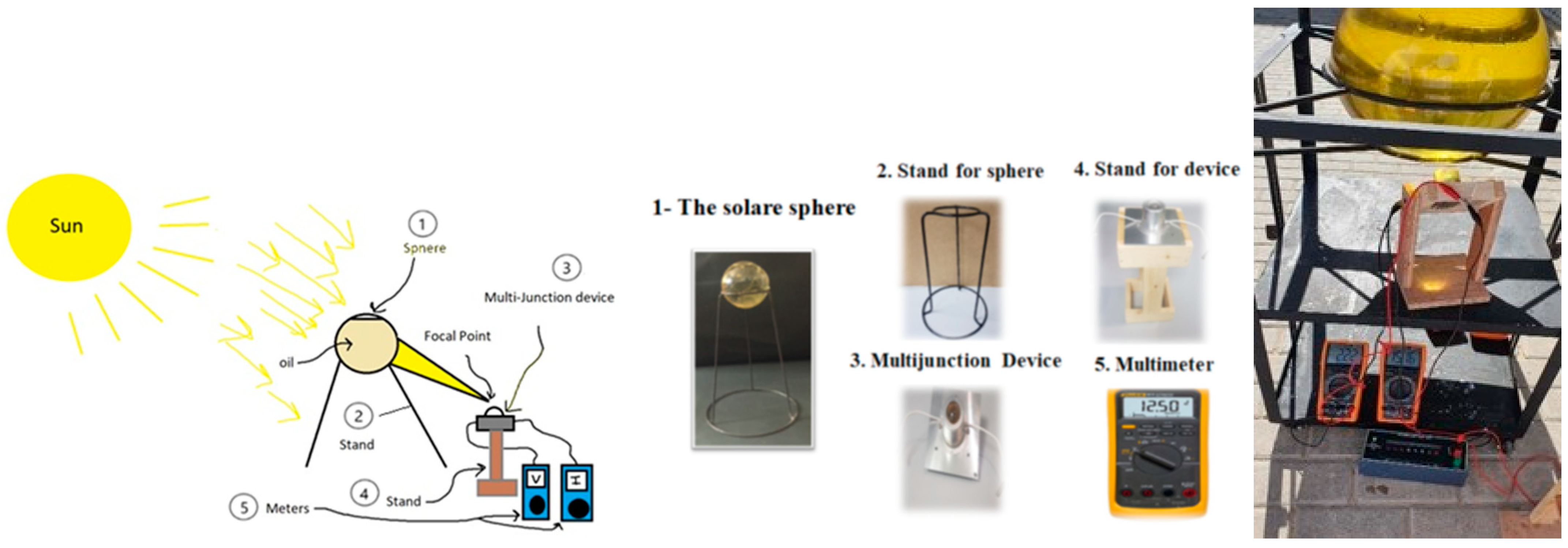
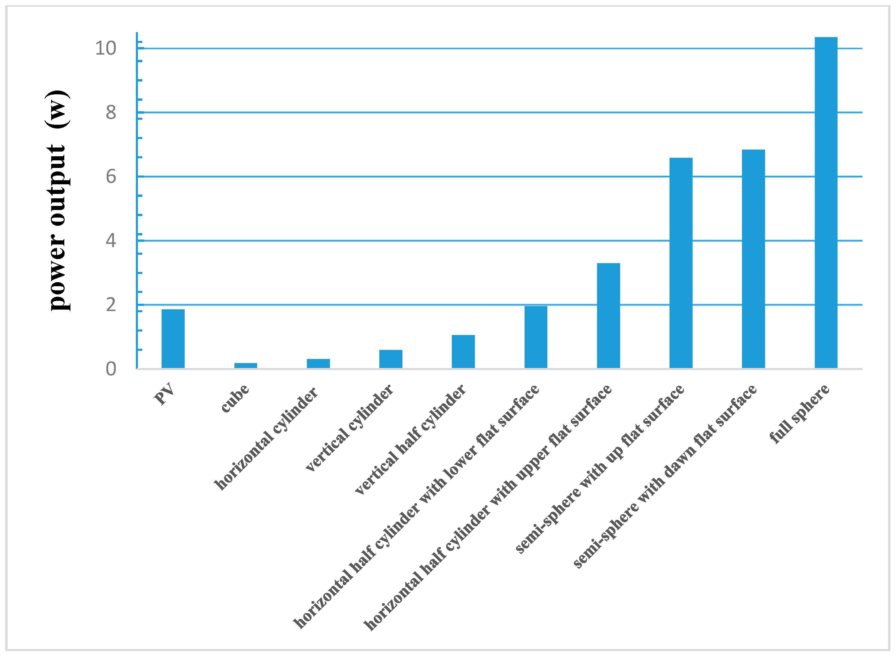
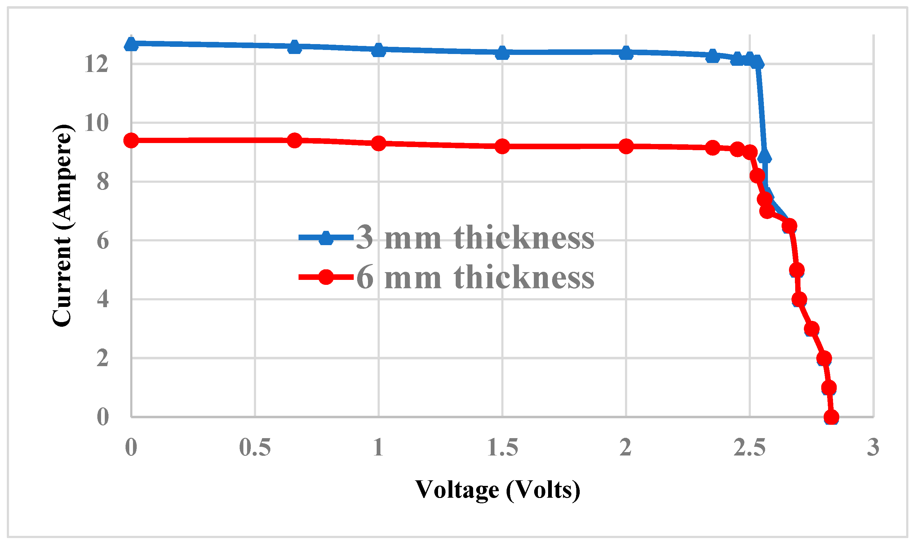
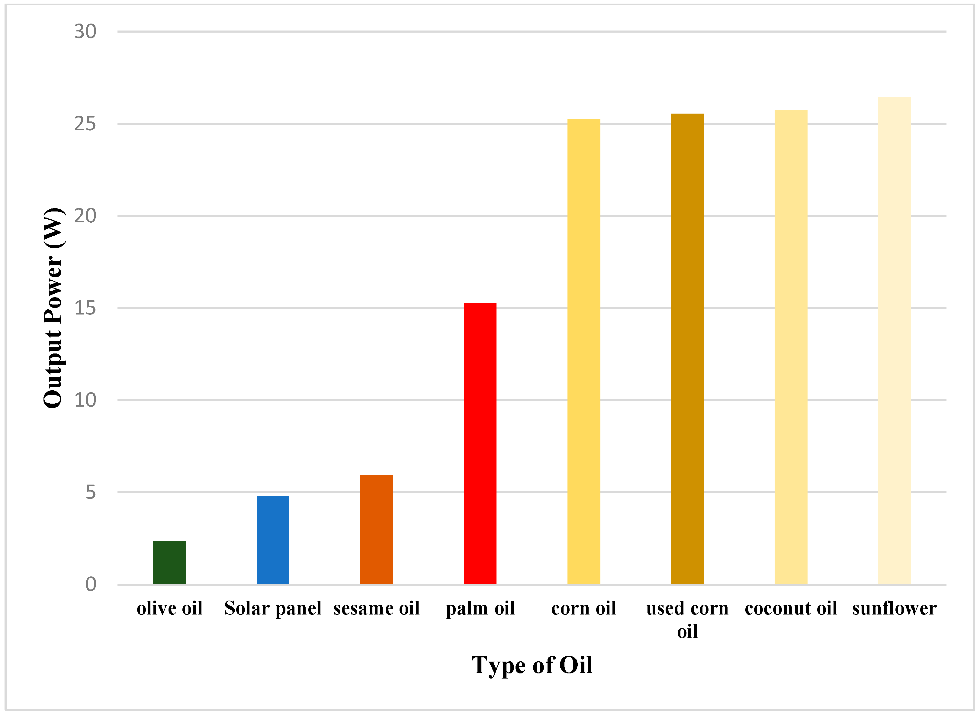
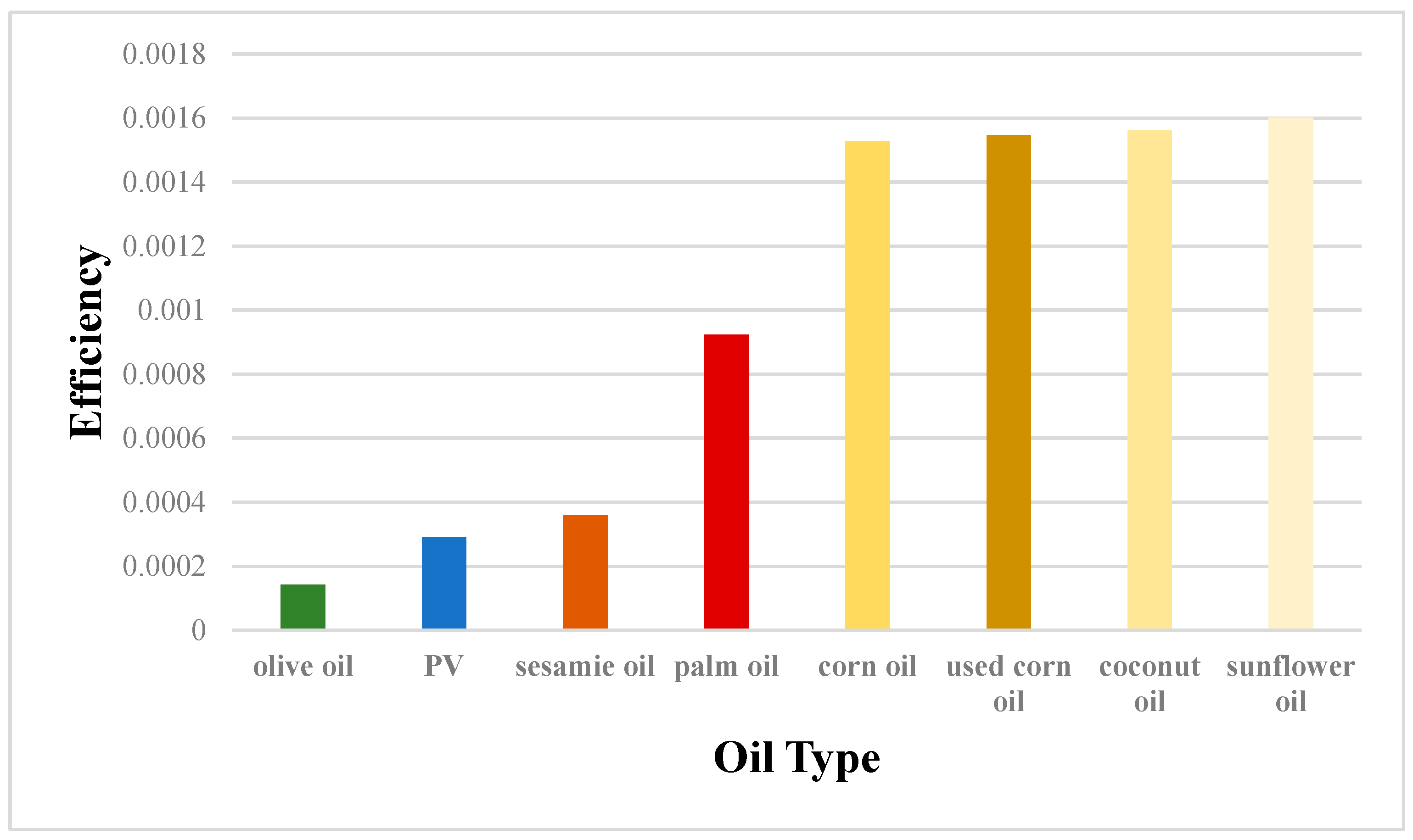
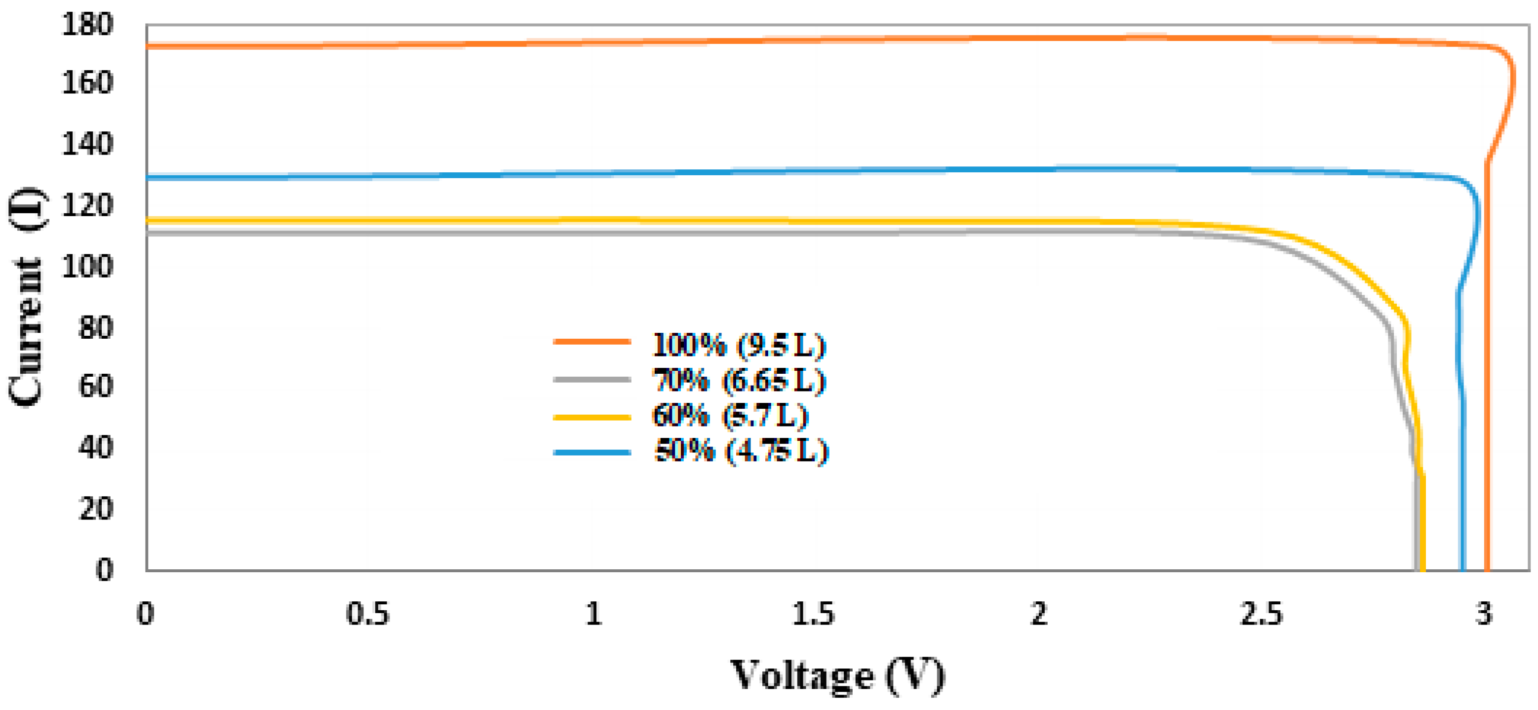
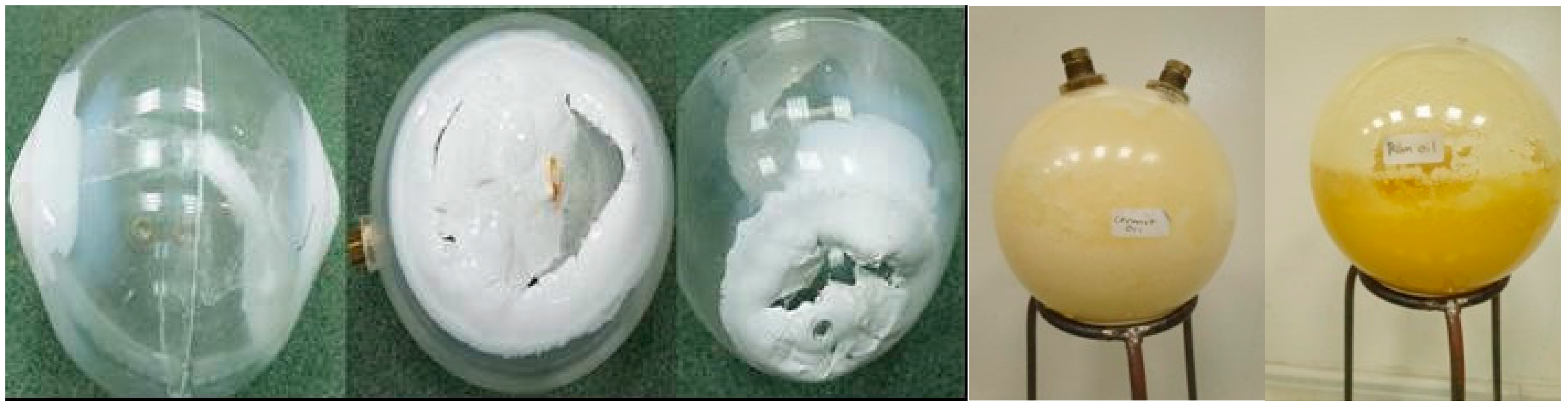
Table 1.
A list of the specifications for the various media/materials.
| Media | Type | Viscosity (Pa·s) | Density (kg/m3) | Chemical Formula |
|---|---|---|---|---|
| Air | Normal | 0.00001864 | 1.225 | N2, O2, Ar, Co2, ANe, He, Ch4, Kr, H2, Xe |
| Alcohol | Isopropanol | 2.1 | 0.79 | C3H8O |
| Water | Drink water | 0.00798 | 1000 | H2O |
| Oil | Cooking oil (Corn) | 80 | 910 | C18H36O2 |
| Glass | Borosilicate | 600 | 2500 | SiO2 |
| Crystal | Crystallography | - | 1750 | Arrangement of atoms, molecules, or ions |
| Acrylic | Plexiglas | - | 1150–1200 | or polyacrylate or Polymethyl methacrylate (Acrylic, PMMA) |
Table 2.
The specifications for acrylic.
| T-Conductivity (W/m/K) | T-Expansion (10−6/C) | Density (kg/m3) | Young’s Modulus (GPa) | Yield Strength (MPa) | Tensile Strength (MPa) | Fracture Toughness (MPa·m1/2) | Tm or Tg (°C) | Specific Heat (J/kg·°C) | Resistivity (µohm. cm) | Dielectric Constant (-) | Carbon (kg/kg) | Water (L/kg) | |
|---|---|---|---|---|---|---|---|---|---|---|---|---|---|
| Polymethyl methacrylate (acrylic, PMMA) | 0.084–0.25 | 72–160 | 1200 | 2.2–3.8 | 54–72 | 48–80 | 0.7–1.6 | 85–160 | 1500–1600 | 330 × 1021–3e × 1024 | 3.2–3.4 | 6.5–7.1 | 72–80 |
Table 3.
Sphere sizes and volumes.
| Type | Diameter: D cm | Sectional Area cm2 | Surface Area cm2 | Volume cm3 |
|---|---|---|---|---|
| Sphere | 10 | 78.54 | 314.16 | 523.33 |
| Sphere | 12 | 113.10 | 452.39 | 904.32 |
| Sphere | 14 | 153.94 | 615.75 | 1436.03 |
| Sphere | 30 | 706.86 | 2827.43 | 14,130.00 |
| Oil | Viscosity (kg/ms) | Reflective Index | Density (kg/m3) | Color | Power Output |
|---|---|---|---|---|---|
| Sunflower | 0.0492 | 1.474 | 918.8 | Clear and slightly/bright gold | 26.44 |
| Corn | 0.0349 | 1.470 | 922.3 | Pale yellow | 25.22 |
| Coconut | 0.0550 | 1.430 | 924.3 | Slightly yellow | 25.79 |
| Palm | 0.0430 | 1.458 | 904.0 | Reddish orange | 15.25 |
| Olive | 0.0400 | 1.470 | 895.0 | Dark green | 2.37 |
| Sesame | 0.0349 | 1.472 | 899.0 | Dark reddish-brown | 5.92 |
Table 5.
The volume of filled oil of the sphere (oil content of the sphere).
| Percentage of the Sphere’s Oil Being Filled % | Amount of Oil Inside the Sphere That Is Equivalent in Volume (Litter) |
|---|---|
| 25 | 2.375 |
| 50 | 4.75 |
| 60 | 5.7 |
| 70 | 6.65 |
| 100 | 9.5 |
Disclaimer/Publisher’s Note: The statements, opinions and data contained in all publications are solely those of the individual author(s) and contributor(s) and not of MDPI and/or the editor(s). MDPI and/or the editor(s) disclaim responsibility for any injury to people or property resulting from any ideas, methods, instructions or products referred to in the content. |
© 2024 by the author. Licensee MDPI, Basel, Switzerland. This article is an open access article distributed under the terms and conditions of the Creative Commons Attribution (CC BY) license (https://creativecommons.org/licenses/by/4.0/).
Share and Cite
MDPI and ACS Style
Abdulmouti, H. Innovative Approach of Concentrated Solar Sphere to Generate Electrical Power. Energies 2024, 17, 1956. https://doi.org/10.3390/en17081956
AMA Style
Abdulmouti H. Innovative Approach of Concentrated Solar Sphere to Generate Electrical Power. Energies. 2024; 17(8):1956. https://doi.org/10.3390/en17081956
Chicago/Turabian StyleAbdulmouti, Hassan. 2024. "Innovative Approach of Concentrated Solar Sphere to Generate Electrical Power" Energies 17, no. 8: 1956. https://doi.org/10.3390/en17081956
Note that from the first issue of 2016, this journal uses article numbers instead of page numbers. See further details here.