Research on Capacity Optimization Configuration of Renewable Energy Off Grid Hydrogen Production System Considering Collaborative Electrolysis

Shida Shanneng New Energy College, China University of Petroleum (East China), Qingdao 266580, China
*
Author to whom correspondence should be addressed.
Energies 2024, 17(8), 1962; https://doi.org/10.3390/en17081962
Submission received: 13 March 2024
/
Revised: 29 March 2024
/
Accepted: 5 April 2024
/
Published: 20 April 2024
(This article belongs to the Section A: Sustainable Energy)
Abstract
:This study proposes a multitype electrolytic collaborative hydrogen production model for optimizing the capacity configuration of renewable energy off grid hydrogen production systems. The electrolytic hydrogen production process utilizes the synergistic electrolysis of an alkaline electrolyzer (AEL) and proton exchange membrane electrolyzer (PEMEL), fully leveraging the advantages of the low cost of the AEL and strong regulation characteristics of the PEMEL. For the convenience of the optimization solution, the article constructs a mixed linear optimization model that considers the constraints during system operation, with the objective function of minimizing total costs while meeting industrial production requirements. Gurobi is used for the optimal solution to obtain the optimal configuration of a renewable energy off grid hydrogen production system. By comparing and analyzing the optimal configuration under conventional load and high-load conditions, it is concluded that collaborative electrolysis has advantages in improving resource consumption and reducing hydrogen production costs. This is of great significance for optimizing the capacity configuration of off grid hydrogen production systems and improving the overall economic benefits of the system.
1. Introduction
Hydrogen is considered one of the most promising clean energy sources, with the characteristics of high energy density, zero emissions, and no pollution. It is an important research object to solve the problems of increasingly depleted petroleum and petrochemical resources and fossil fuel pollution and promote the development of green energy fields [1]. However, how to efficiently utilize electricity to produce hydrogen is an important issue that hinders large-scale hydrogen production [2]. Utilizing renewable energy sources such as wind and solar power to electrolyze water for hydrogen production is an important means to solve this problem [3]. With the continuous infiltration of new energy sources such as photovoltaics and wind power, the installed capacity of new energy continues to expand [4]. Fully utilizing renewable energy sources such as wind and solar power to electrolyze hydrogen can not only efficiently produce hydrogen but also improve the consumption rate of new energy, achieving the goal of improving new energy consumption and reducing the impact of new energy grid connection [5,6]. It is a powerful means to reduce fossil energy consumption and carbon emissions [7]. At the same time, it is crucial for the stable operation of the off grid hydrogen production system to reasonably allocate the capacity of each subsystem in the system.
From the perspective of hydrogen production system topology, existing research on off grid hydrogen production systems has delved into different energy storage perspectives and hydrogen storage and transportation methods and calculated capacity configurations through algorithms. Han et al. [8] constructed a wind hydrogen energy system with the objective of minimizing system investment cost, operating cost, and maintenance cost for capacity optimization configuration. They analyzed the impact of different hydrogen purchase channels on capacity configuration and the impact of daily hydrogen load changes on capacity configuration; Si et al. [9] studied the capacity configuration of wind power hydrogen production systems considering thermal balance; Abuduvayiti et al. [10] determine the Nash equilibrium point for maximizing the benefits of each game participant in the hydrogen production system and solve the optimal system capacity configuration under the target situation; Yang Zijuan et al. [11] optimized and calculated the capacity configuration of the hydrogen energy system from the perspectives of rotating operation of electrolytic cells and hydrogen production transportation when the pipeline transportation of hydrogen meets the hydrogen blending ratio; Wan Yongjiang et al. [12] calculated the economic benefits based on the capacity configuration of wind solar hydrogen electrolysis cells under different typical days; Deng Zhihong et al. [13] studied the hydrogen production efficiency characteristics of electrolytic cells and proposed an optimization method for wind hydrogen system capacity configuration, considering the hydrogen production efficiency characteristics, in response to the intermittent operation of electrolytic cells caused by wind power hydrogen production; Huang Dawei et al. [14] analyzed the structure and operational characteristics of wind power hydrogen production systems, with a focus on proposing a hydrogen production capacity configuration method for the hydrogen production system to absorb wind power curtailment, in order to improve the wind power consumption rate. The above research, based on the perspective of hydrogen production system topology construction, did not fully consider the safety of the system when the onboard load is in a high-load state, and the topology construction did not consider the factor of preventing collapse.
From the perspective of electrolytic hydrogen production, currently, alkaline water electrolysis cells have the characteristics of low cost, mature commercial promotion, and weak regulation ability. Proton exchange membrane electrolysis cells have the characteristics of strong regulation ability but high cost [15]. Research is conducted on an off grid hydrogen production system that combines the advantages of two types of electrolysis cells to jointly participate in the electrolysis process, fully leveraging their advantages to make up for shortcomings, reduce configuration costs, and improve fluctuation adaptability.
In response to the above research, the contributions of this study are as follows:
- (1)
- This study proposes an optimized configuration model for a renewable energy off grid hydrogen production system using an alkaline water electrolysis tank and proton exchange membrane electrolysis tank for synergistic electrolysis;
- (2)
- This study constructed a renewable energy off grid hydrogen production system topology, combined with the operating characteristics of subunits such as electrolysis cells, fuel cells, energy storage, and hydrogen storage, and analyzed the operating characteristics of proton exchange membrane electrolysis cells and alkaline water electrolysis cells, which jointly participated in the electrolysis process;
- (3)
- Based on the optimization model, this study uses the Gurobi solver for solving, taking into account two types of scenarios: conventional load and high load, to verify the effectiveness of topology in ensuring stable system operation. Through comparative analysis, the economic benefits and effectiveness of the proposed method in this study are effectively confirmed.
2. Modeling of Off Grid Hydrogen Production System
2.1. Structure of Renewable Energy Off Grid Hydrogen Production System
Building a reasonable and reliable off grid hydrogen production system topology is an important prerequisite for efficient utilization of renewable energy for hydrogen production. As shown in Figure 1, the source side of the hydrogen production system is composed of wind turbines and photovoltaic power generation, and energy storage is used as a power regulating device to participate in smoothing fluctuations and maintaining system operation. Fuel cells are used to burn hydrogen for energy supply when the source side and energy storage cannot meet the load requirements under extremely high load conditions. In this study, the energy consumption of the electricity load in the auxiliary system is relatively low and easy to analyze compared to the aforementioned units, and the electricity load is simplified.
2.2. Mathematical Model of Off Grid Hydrogen Production System
- (1)
- Wind turbine and photovoltaic model: Wind turbines and photovoltaic arrays convert renewable energy into electricity. When photovoltaic power cannot be generated normally without sunlight at night, wind turbines can be used to generate electricity and supply electricity, and their output determines the power supply of the entire system. The mathematical model of the output power of a wind turbine can be represented by Formulas (1)–(4):
The mathematical model of photovoltaic power generation can be represented by the following formula:
where denotes the output power of the solar panel; denotes the photovoltaic conversion rate; denotes the solar irradiance; denotes the illuminated area of the solar panel.
- (2)
- Electrolytic cell output model
The process of hydrogen production by electrolysis in an electrolytic cell is a nonlinear function of the current and power of the electrolytic cell [16,17], represented by . The specific process is related to the electrochemical reaction process [18], and the hydrogen production efficiency shows a nonlinear relationship with the input power of the electrolytic cell [13,19,20], defined as Equation (7):
where denotes the Faraday efficiency; denotes the thermal neutral voltage; denotes the electrolytic cell voltage.
The hydrogen production rate in the electrolysis hydrogen production process [11] can be expressed as:
where denotes the power consumption per unit of hydrogen gas; denotes the power of the electrolytic cell.
The hydrogen production efficiency of the electrolytic cell can be represented by segmented linearization [21], which facilitates the construction of a mixed linear optimization model, as shown in Formulas (9)–(14).
where denotes the total number of segments; and denote the coefficients and constant terms of each segment’s first-order term; denotes the inflection point of each independent variable in each segment; denotes the corresponding state variable in each segment, and piecewise linearization can be solved in the solver.
3. MILP Optimization Model Construction
3.1. Objective Function
The objective function consists of construction cost CAPEX and operating cost OPEX, and the specific expression of the objective function is as follows:
where denotes different types of components in the system; denotes the investment cost per unit capacity; denotes the maintenance cost per unit capacity; denotes the device capacity; denote the start-up cost and shutdown cost; and denote the start-up and shutdown status; denotes the cost of battery charging and discharging losses.
3.2. Constraints
The constraints include system energy and hydrogen balance, battery, fuel cell, hydrogen storage, electrolytic cell, photovoltaic and wind power generation constraints:
- (1)
- Electric and hydrogen energy balance constraints: The electric and hydrogen energy balance constraints of the system at any time are expressed as follows:
- (2)
- Electrolytic cell constraints:
- (3)
- Energy storage and hydrogen storage: Battery energy storage is used for energy storage, while hydrogen storage is used for hydrogen storage. The specific constraint model is represented as follows:
- (4)
- Fuel cells: Fuel cells use the generated hydrogen to generate electricity, with the following constraints:
- (5)
- Constraints for wind and photovoltaic power generation:
Based on the optimization model and constraints, Gurobi is used to solve.
4. Example Analysis
This article includes a typical day in Inner Mongolia, China, which requires a daily hydrogen production of no less than 1000 kg. The optimization configuration is carried out separately in the electrolysis cell for collaborative electrolysis, the PEMEL for separate electrolysis, and the AEL for separate electrolysis, and the differences are further analyzed.
4.1. Configuration of Off Grid Hydrogen Production System under Conventional Load
Based on typical daily data of regional wind and solar resources and hydrogen production requirements, the capacity configuration of off grid hydrogen production system unit components was carried out. Three types of electrolysis were considered: mixed electrolysis of the PEMEL and AEL, AEL electrolysis, and PEMEL electrolysis. The results are shown in Table 1 and Table 2:
The specific analysis of three different types of electrolysis is as follows:
Type 1: AEL electrolysis.
As shown in Table 2, when using the AEL for hydrogen production, although the total investment is lower than the cost of two types of electrolytic cells for collaborative electrolysis, due to the low regulation rate and high start-up power of AEL electrolytic cells, the power generation system has a higher energy storage configuration to store electricity loads. When energy storage cannot store electricity loads, a higher curtailment rate will occur, which is not conducive to improving the consumption of renewable resources. Considering the penalty of power abandonment, the overall revenue of the system is lower than that of the mixed electrolysis configuration of two types of electrolysis cells (Figure 2, Figure 3 and Figure 4 and Table 3).
Type 2: PEMEL electrolysis.
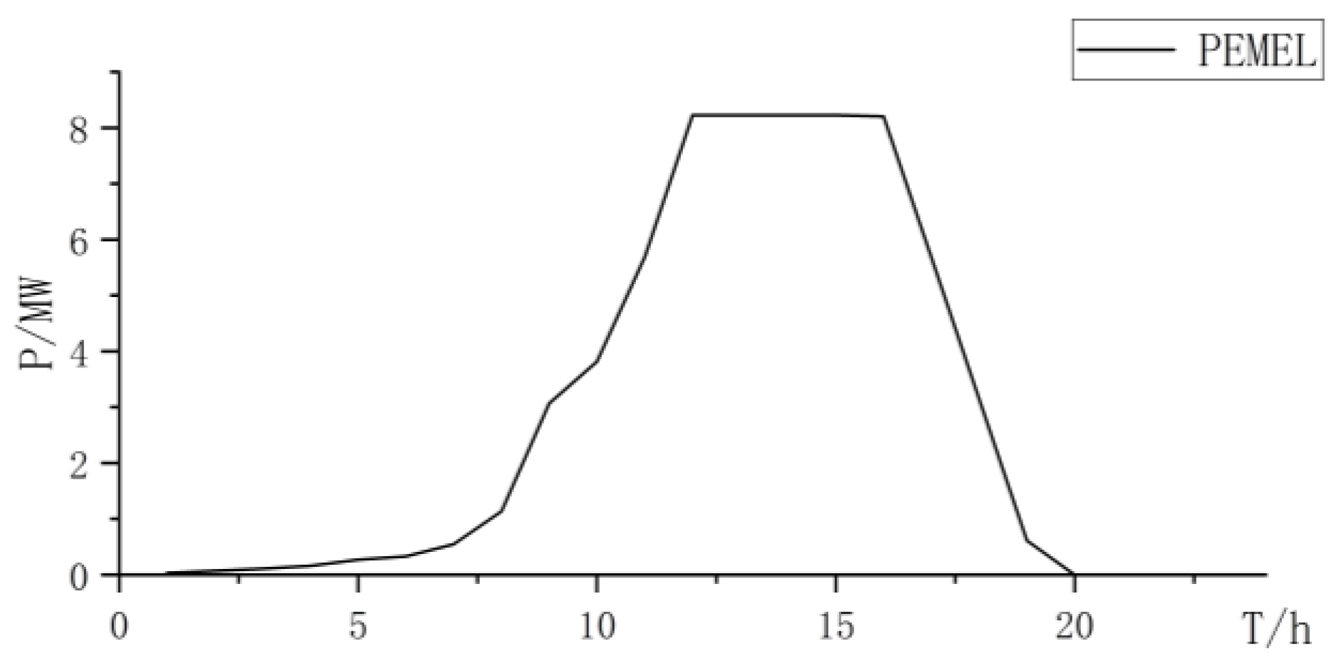
When using PEMELs for hydrogen production, PEMELs have good dynamic performance and strong ability to absorb renewable resources. However, due to the disadvantages of high cost and maintenance costs of PEMELs, the total cost is relatively high (Figure 5, Figure 6 and Figure 7 and Table 4):
Type 3: Collaborative electrolysis.
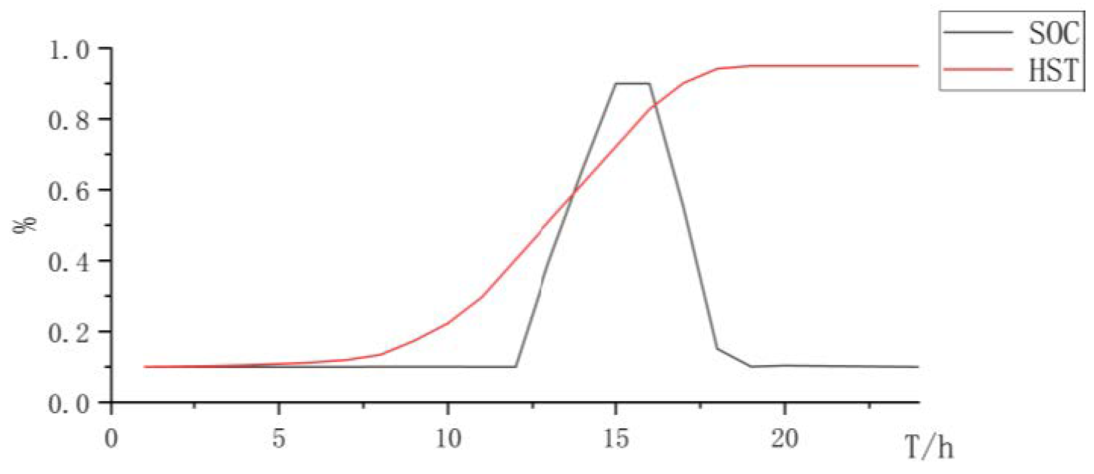
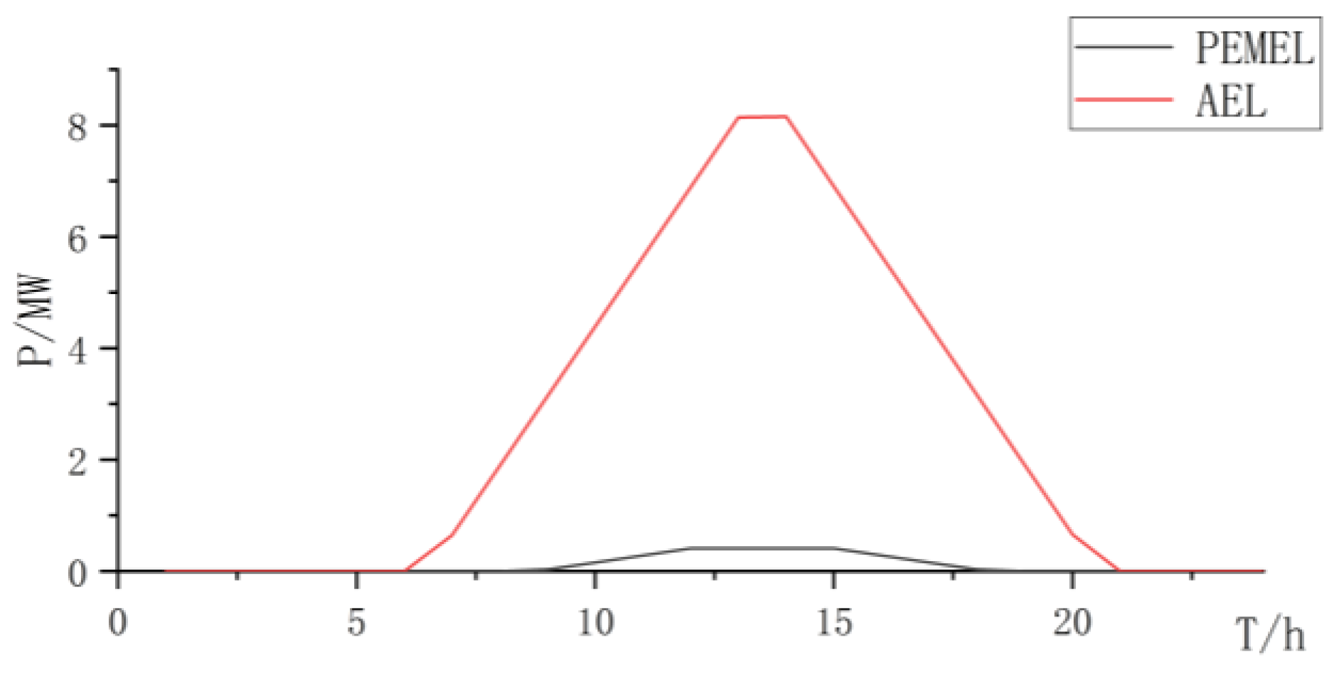
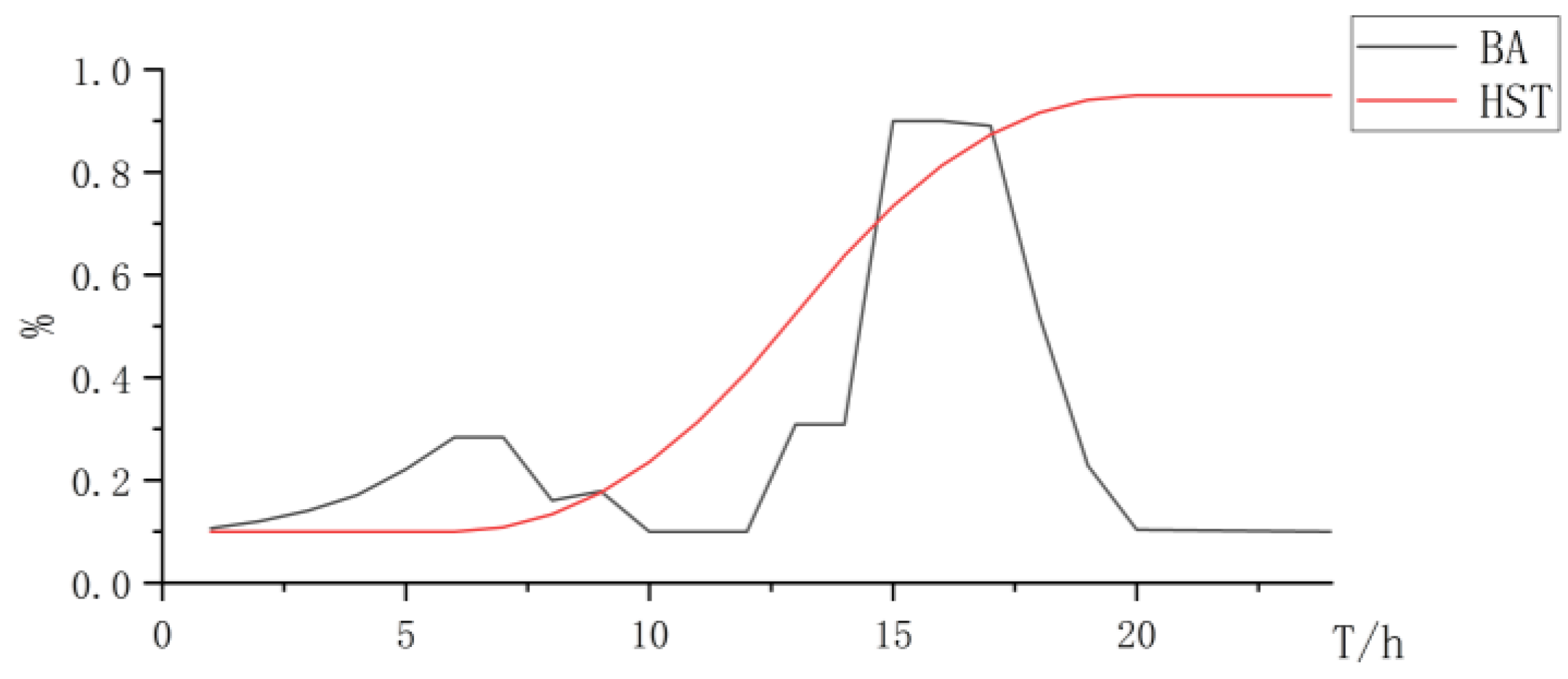
The synergistic electrolysis of hydrogen production using the PEMEL and AEL can fully leverage the advantages of the low cost of the AEL and strong response characteristics of the PEMEL, with complementary advantages (Figure 8, Figure 9 and Figure 10 and Table 5).
Based on the above analysis, the synergistic electrolysis of hydrogen production using the PEMEL and AEL can leverage the advantages of the low cost of AEL and strong dynamic performance of the PEMEL, improve the consumption rate of renewable resources, and reduce investment costs.
4.2. Configuration of Off Grid Hydrogen Production System under High Load
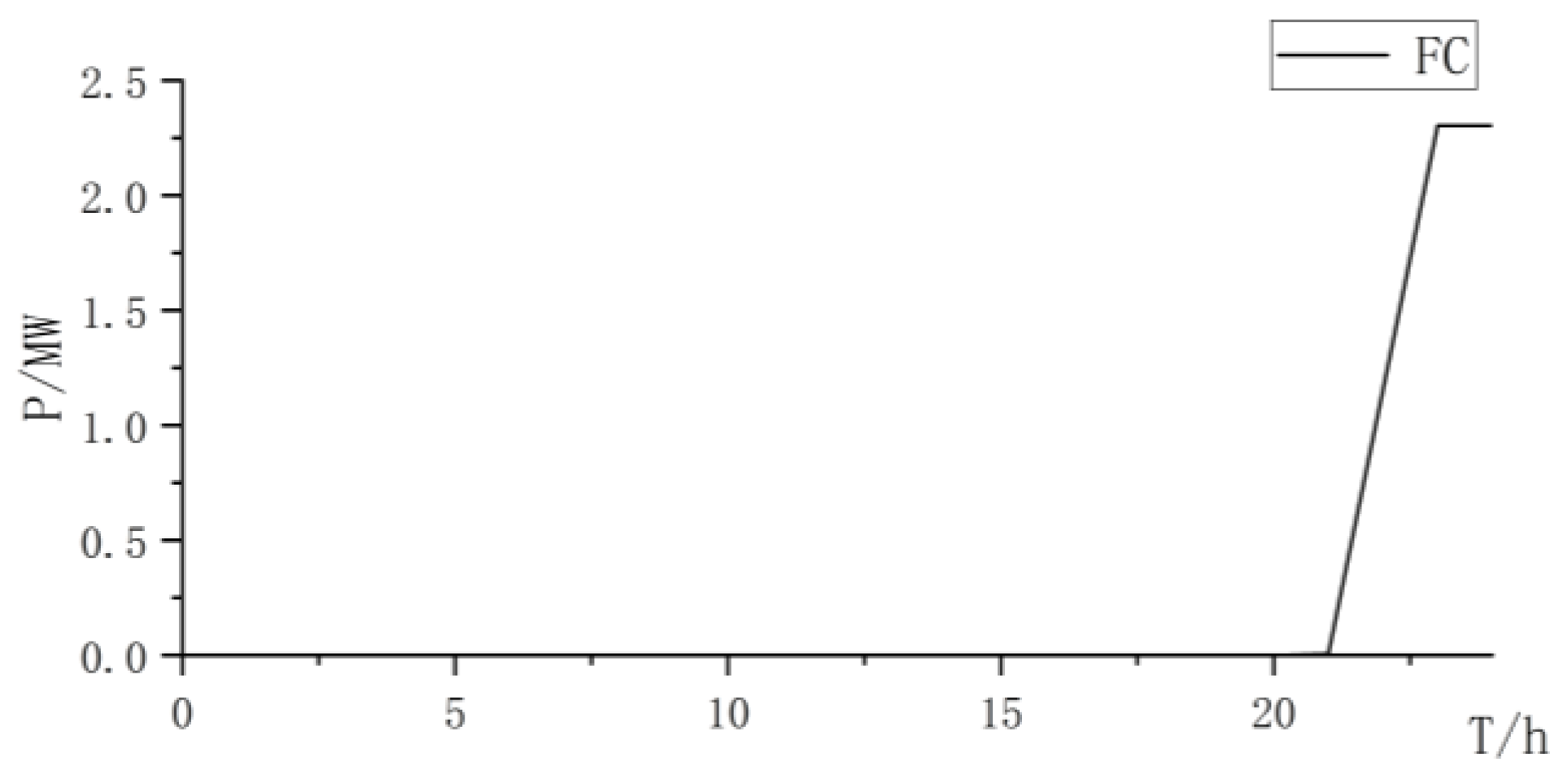
When the system has a high-load state, renewable energy generation cannot meet the electrical load requirements. In order to meet the electrical load requirements, the system uses energy storage, fuel cells, etc. to supply electricity. When the energy storage cannot meet the electrical load requirements of the system, the system uses hydrogen gas that has already been electrolyzed from the fuel cell combustion part to generate electricity to meet the electrical load requirements of the system. The configuration results are shown in Table 6:
When there is a high-load period in the system, the specific situations of the three types of electrolysis are as follows:
When the system is under a high-load state, due to the fuel cell output, the electrolytic cell will no longer electrolyze hydrogen production. The hydrogen production system is equipped with high power generation and electrolysis power. The hydrogen production system will increase the hydrogen production rate during the period when the system load requirements have been met to ensure that the total hydrogen production requirements are met while dealing with the hydrogen consumption state of the fuel cell operation.
The three types of electrolysis all increase the electrolysis power of the electrolysis cell, and the abandonment rate of the AEL for hydrogen production alone is relatively high (Table 7). When using the PEMEL alone for hydrogen production, due to its high cost, although the consumption of renewable resources is considerable, the overall construction cost is relatively high. Therefore, using the PEMEL alone for hydrogen production does not have an overall advantage.
The synergistic electrolysis of the AEL and PEMEL can fully combine the advantages of the two types of electrolysis tanks, which can reduce production costs and promote the consumption of renewable resources.
5. Conclusions
This article proposes a collaborative electrolytic capacity optimization configuration model for renewable energy off grid hydrogen production systems. The study comprehensively considered the operating characteristics of various subsystems in the renewable energy off grid hydrogen production system, such as an electrolyzer, battery, hydrogen storage, wind turbine and photovoltaics, and fuel cell, and established an optimization model. The optimal configurations to ensure the stable operation of the auxiliary system under conventional load and high-load conditions are discussed. Using typical daily data testing and analysis, the conclusions are as follows:
(1) The optimization model proposed by the research can fully consider production needs and regional resource characteristics to optimize the capacity allocation of subsystems for renewable resource off grid hydrogen production systems. For conventional and high-load conditions, configuring the capacity of each subsystem effectively ensures the safe and stable operation of the system and prevents the collapse of the hydrogen production system.
(2) The combined electrolysis of the PEMEL and AEL proposed by the research can fully leverage the advantages of the low cost of the AEL and fast response speed of the PEMEL, improve the consumption of renewable resources, and reduce production costs.
The joint electrolysis optimization model proposed by this research can effectively improve the consumption rate of new energy and reduce the cost of hydrogen production systems.
Author Contributions
Conceptualization, Z.K.; methodology, Z.K.; software, S.L.; validation, S.L.; writing—original draft preparation, S.L.; writing—review and editing, Z.K.; visualization, S.L.; funding acquisition, Z.K. All authors have read and agreed to the published version of the manuscript.
Funding
This research was funded by National Natural Science Foundation of China under Grant No. 52241702 (project: Key technologies of electric energy conversion, protection and coordinated control for DC off-grid hydrogen generation system integrated with renewable energy).
Data Availability Statement
Some reference data has already been reflected in the main text, and the author can be contacted for other data if needed.
Conflicts of Interest
The authors declare no conflicts of interest.
References
- Jiang, M.; Xiao, P.; Liu, R.; Huang, B. The role of hydrogen energy in China’s future energy system and preliminary study on the route of re-electrification. Therm. Power Gener. 2020, 49, 1–9. (In Chinese) [Google Scholar] [CrossRef]
- Huang, Y.; Ding, T.; Li, Y.; Li, L.; Chi, F.; Wang, K.; Wang, X.; Wang, X. Decarbonization Technologies and Inspirations for the Development of Novel Power Systems in the Context of Carbon Neutrality. Proc. CSEE 2021, 41 (Suppl. S1), 28–51. (In Chinese) [Google Scholar] [CrossRef]
- Cheng, C.; Chen, Z.; Sun, P.; He, M. Capacity configuration optimization for wind solar hybrid power system based on typical meteorological conditions. Acta Energiae Solaris Sin. 2021, 42, 110–114. (In Chinese) [Google Scholar] [CrossRef]
- Yang, Y.; Yu, H.-Y.; Lu, G.; Wang, L.-M.; Zhao, Y.; Hao, L.-S.; Ren, D.-M.; Fang, W.; An, H.-Z.; Cai, G.-T. Interview on the unprecedented changes of energy geopolitics and national energy security. J. Nat. Resour. 2020, 35, 2803–2820. (In Chinese) [Google Scholar] [CrossRef]
- Hao, S.; Jiancheng, Z.; Ning, W. Energy Management Strategy of Large-scale Hybrid Energy Storage System Based on Layered Optimization. High Volt. Eng. 2018, 44, 1177–1186. (In Chinese) [Google Scholar] [CrossRef]
- Bai, Z.; Han, Y.; Wang, Z.; Li, Q.; Xu, H.; Han, Y.; Wang, S. Wind-solar hybrid hydrogen production system and capacity optimization based on power allocation strategy. Oil Gas Storage Transp. 2023, 42, 910–921943. (In Chinese) [Google Scholar] [CrossRef]
- Zao, G.; Qian, G.; Wang, S. Analysis on green and low-carbon development path for power industry to realize carbon peak and carbon neutrality. Huadian Technol. 2021, 43, 11–20. (In Chinese) [Google Scholar] [CrossRef]
- Han, Z.; Li, C.; Yuan, S.; Dong, Y.; Ma, S. Research on Optimal Allocation of Hybrid Energy Storage System Capacity for Wind Power Hydrogen Production. Northeast. Electr. Power Technol. 2022, 43, 56–62. (In Chinese) [Google Scholar] [CrossRef]
- Si, Y.; Chen, L.; Chen, X.; Mengyu, G.; Linrui, M.; Shengwei, M. Optimal capacity allocation of hydrogen energy storage in wind-hydrogen hybrid system based on distributionally robust. Electr. Power Autom. Equip. 2021, 41, 3–10. (In Chinese) [Google Scholar] [CrossRef]
- Xi, A.; Lv, H.; Chao, Q. Optimal capacity configuration of wind-photovoltaic-hydrogen microgrid based on non-cooperative game theory. Electr. Power Eng. Technol. 2022, 41, 110–118. (In Chinese) [Google Scholar] [CrossRef]
- Yang, Z.; Tian, X.; Wu, W.; Yuan, T. Optimal Capacity Configuration of Wind-Hydrogen-HCNG Coupled Network Considering Combined Electrolyzer Operation. Autom. Electr. Power Syst. 2023, 47, 76–85. (In Chinese) [Google Scholar] [CrossRef]
- Wan, Y.; Han, S.; Yan, Y.; Li, S.; Liu, Y. Research on Optimization of Capacity Allocation of Wind Power and Photovoltaic Hydrogen Production and Economic Analysis of Green Hydrogen. Inn. Mong. Electr. Power 2023, 41, 8–14. (In Chinese) [Google Scholar] [CrossRef]
- Deng, Z.; Jiang, Y. Optimal sizing of a wind-hydrogen system under consideration of the efficiency characteristics of electrolysers. Renew. Energy Resour. 2020, 38, 259–266. (In Chinese) [Google Scholar] [CrossRef]
- Huang, D.; Qi, D.; Yu, N.; Cai, G. Capacity Allocation Method of Hydrogen Production System Consuming Abandoned Wind Power. Acta Energiae Solaris Sin. 2017, 38, 1517–1525. (In Chinese) [Google Scholar] [CrossRef]
- Li, Y.; Deng, X.; Gu, J.; Zhang, T.; Guo, B.; Yang, F.; OuYang, M. Comprehensive Review and Prospect of the Modeling of Alkaline Water Electrolysis System for Hydrogen Production. Automot. Eng. 2022, 44, 567–582. (In Chinese) [Google Scholar] [CrossRef]
- Li, J.; Liang, Z.; Zhao, W.; Li, G.; Li, M. Selection and Evaluation Method of Hydrogen Production System in Hybrid Electrolytic Cell. High Volt. Eng. 2023, 1–12. (In Chinese) [Google Scholar] [CrossRef]
- Huang, Q.; Chen, J.; Cao, X.; Liu, J.; Zhang, Y.; Bao, H. Optimization of wind-photovoltaic complementation hydrogen production system based on synergistic hydrogen production by alkaline electrolyzer and proton exchange membrane electrolyzer. Electr. Power Autom. Equip. 2023, 43, 168–174. (In Chinese) [Google Scholar] [CrossRef]
- Koponen, J. Review of Water Electrolysis Technologies and Design of Renewable Hydrogen Production Systems; Lappeenranta University of Technology: Lappeenranta, Finland, 2015; Available online: https://lutpub.lut.fi/handle/10024/104326 (accessed on 14 December 2023).
- Li, J.; Zhao, J.; Chen, Y.; Mao, L.; Qu, K. Optimal Capacity Configuration of P2H Equipment Considering Dynamic Power Range and Hydrogen Production Efficiency. Trans. China Electrotech. Soc. 2023, 38, 4864–4874+4920. (In Chinese) [Google Scholar] [CrossRef]
- Niu, M.; Hong, Z.; Li, B.; Li, X. Optimal Control Strategy of Wind Power to Hydrogen System Considering Electrolyzer Efficiency Improvement. Acta Energiae Solaris Sin. 2023, 44, 366–376. (In Chinese) [Google Scholar] [CrossRef]
- Xing, X.; Lin, J.; Song, Y.; Song, J.; Mu, S. Intermodule management within a large-capacity high-temperature power-to-hydrogen plant. IEEE Trans. Energy Convers. 2020, 35, 1432–1442. [Google Scholar] [CrossRef]
Figure 1.
Schematic diagram of off grid hydrogen production structure.

Figure 2.
Power curve of wind power and photovoltaic power and curtailment.

Figure 3.
State changes curve of battery and hydrogen storage.

Figure 4.
AEL power curve.
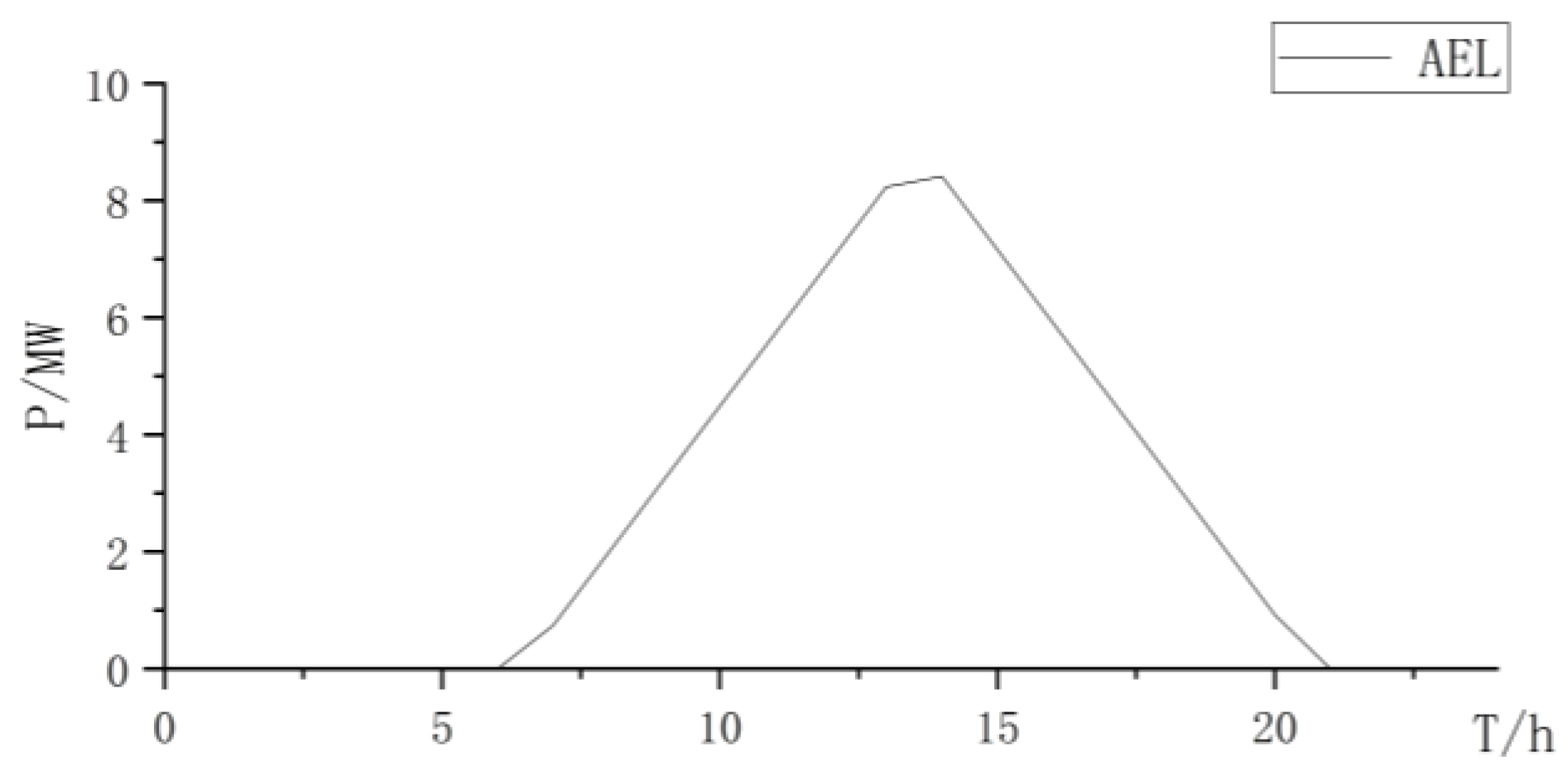
Figure 5.
Power curve of wind power and photovoltaic power and curtailment.
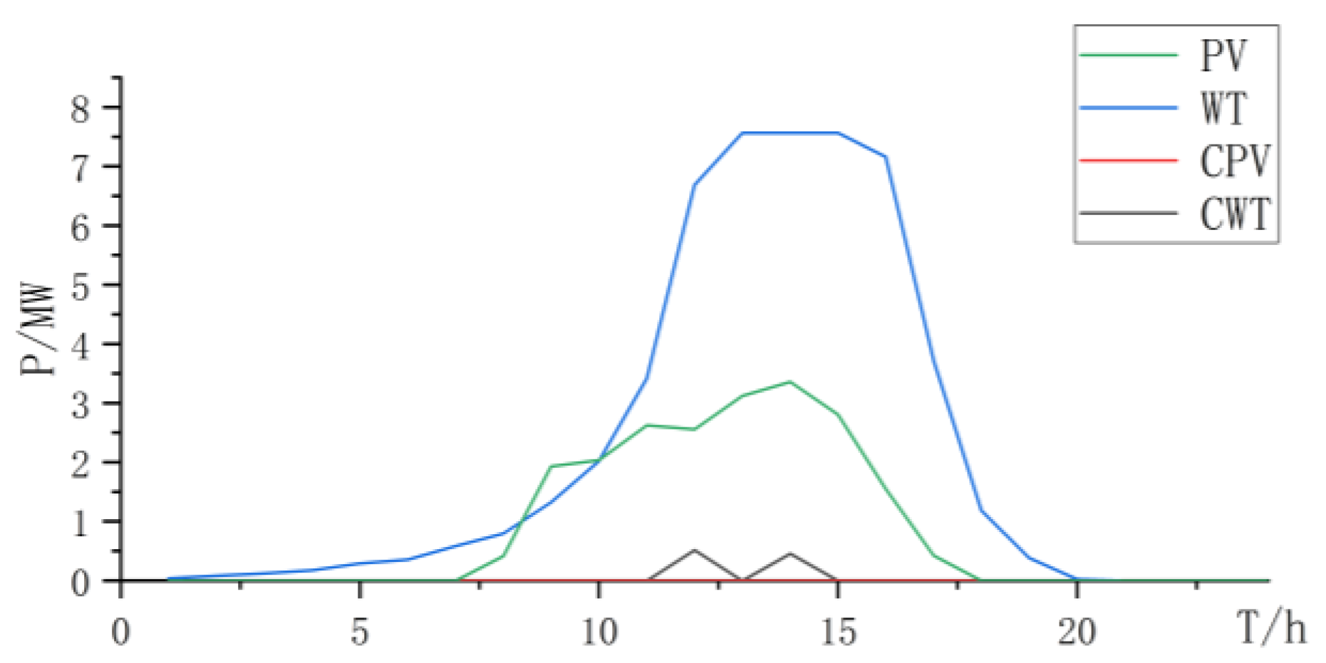
Figure 6.
State changes curve of battery and hydrogen storage.

Figure 7.
PEMEL power curve.

Figure 8.
Power curve of wind power and photovoltaic power and curtailment.
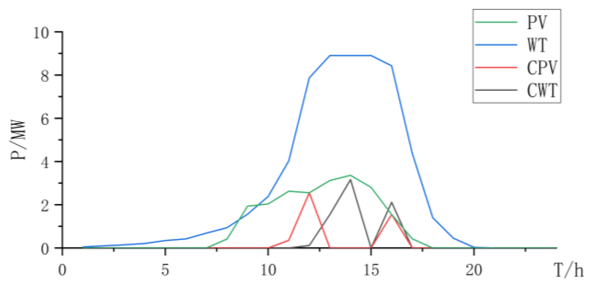
Figure 9.
Collaborative electrolyzer power curve.

Figure 10.
State changes curve of battery and hydrogen storage.

Figure 11.
Power curve of wind power and photovoltaic power and curtailment.
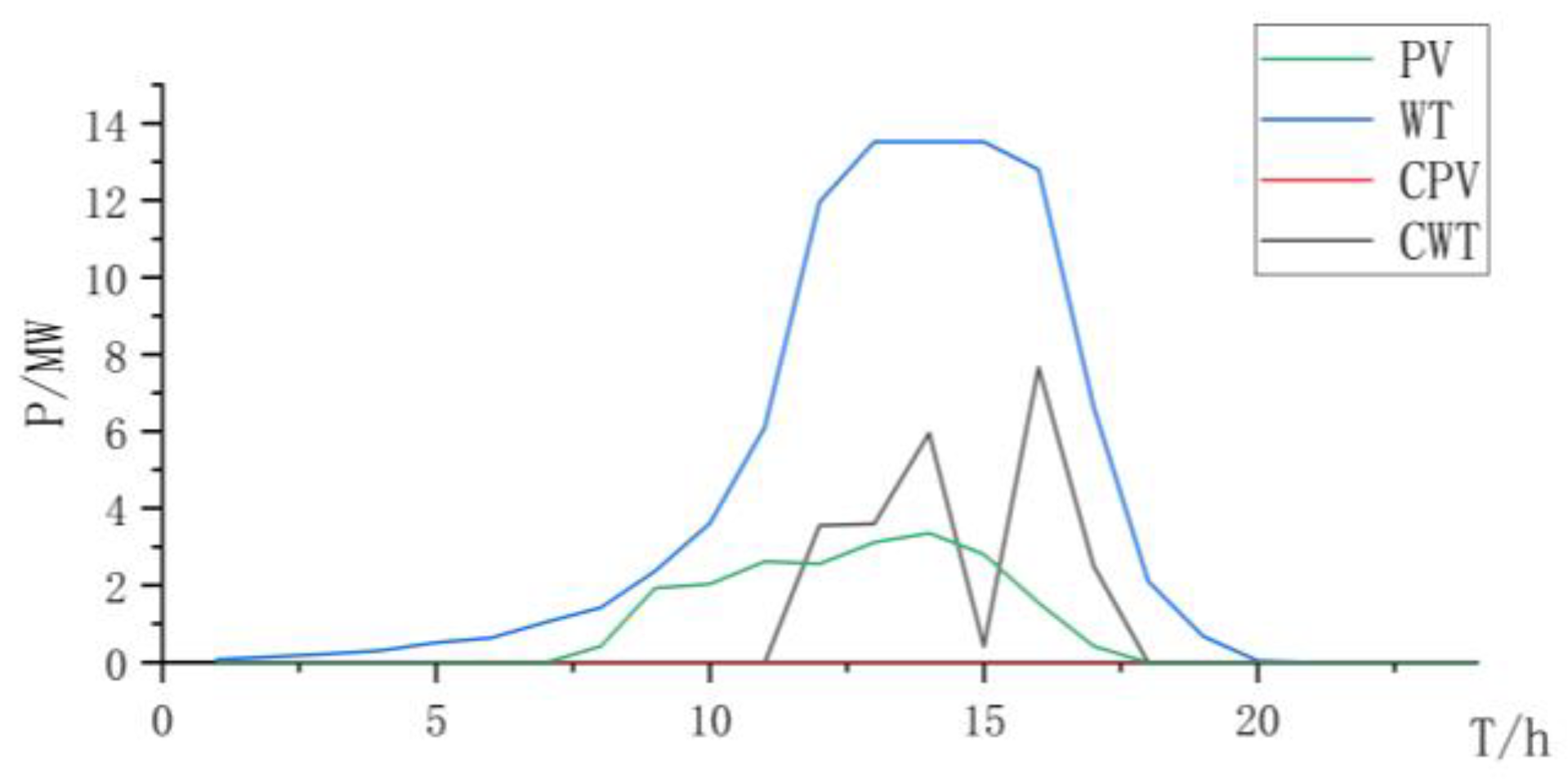
Figure 12.
AEL power curve.
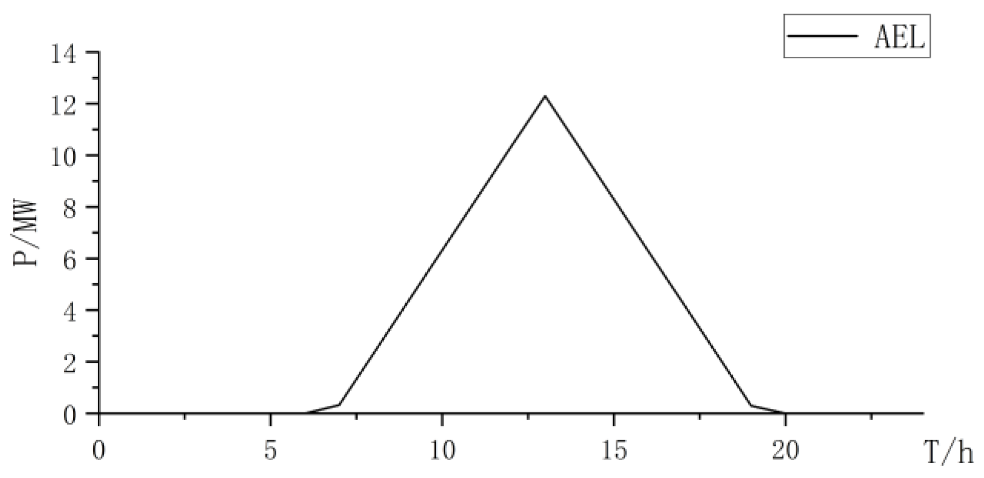
Figure 13.
State changes curve of battery and hydrogen storage.
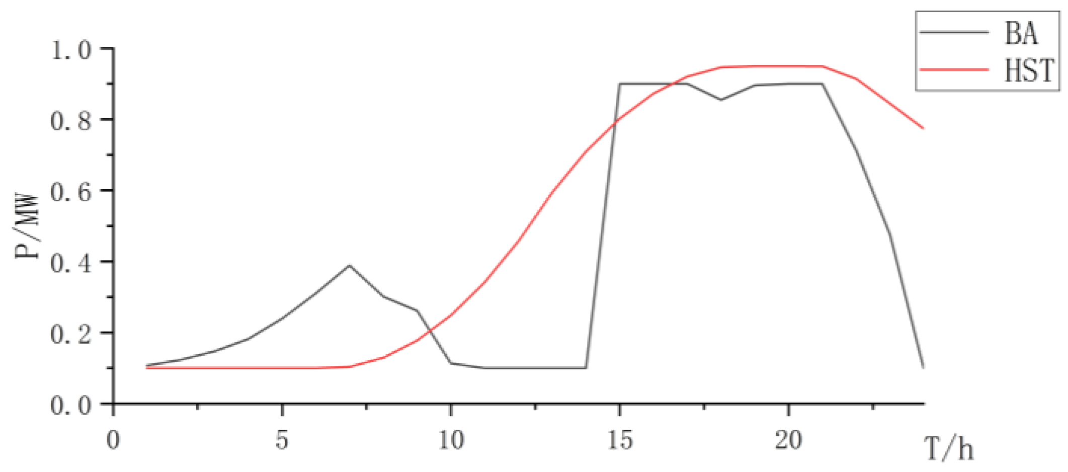
Figure 14.
Fuel cell power curve.

Figure 15.
Power curve of wind power and photovoltaic power and curtailment.
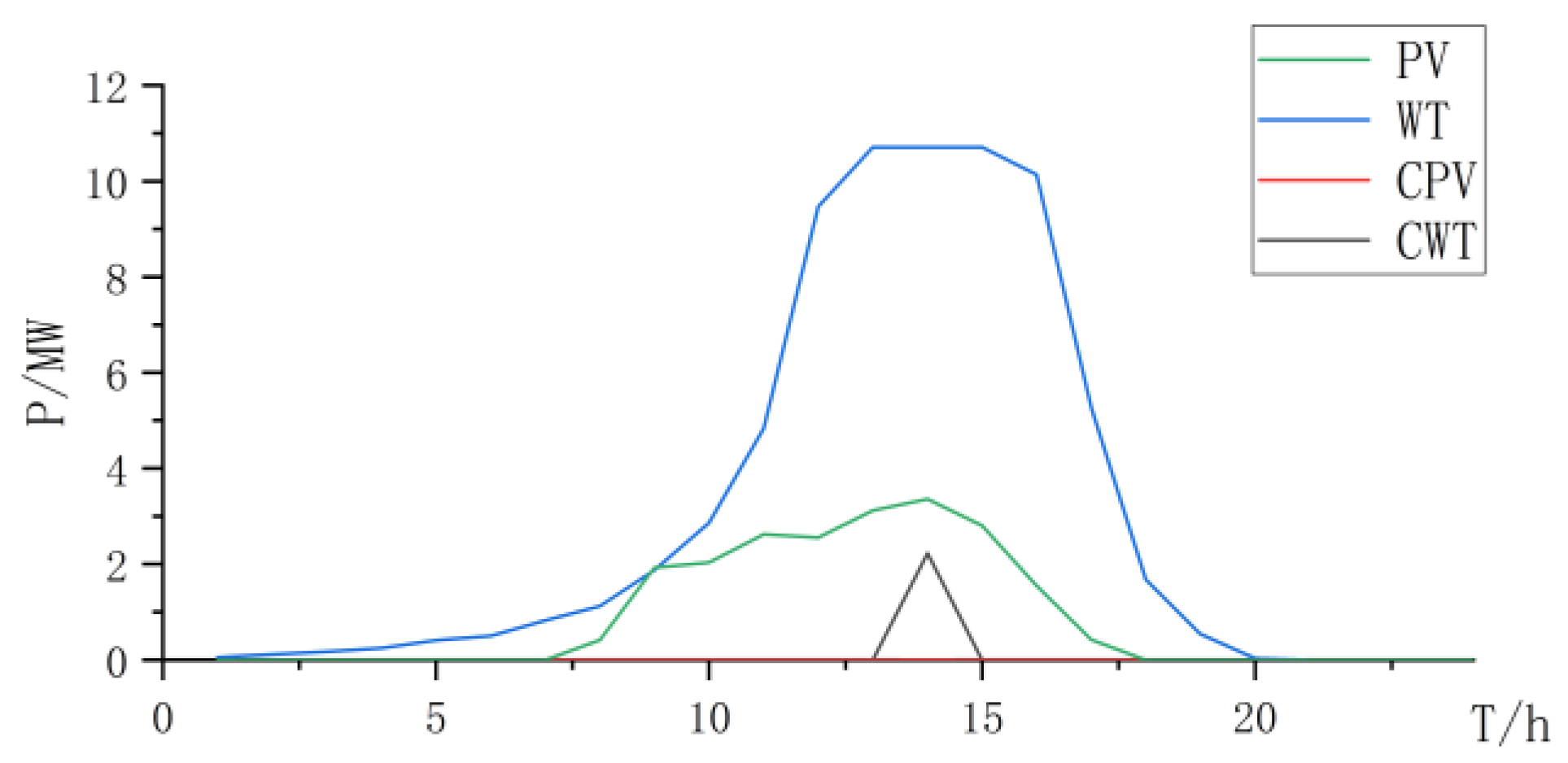
Figure 16.
State changes curve of battery and hydrogen storage.

Figure 17.
PEMEL power curve.

Figure 18.
Fuel cell power curve.
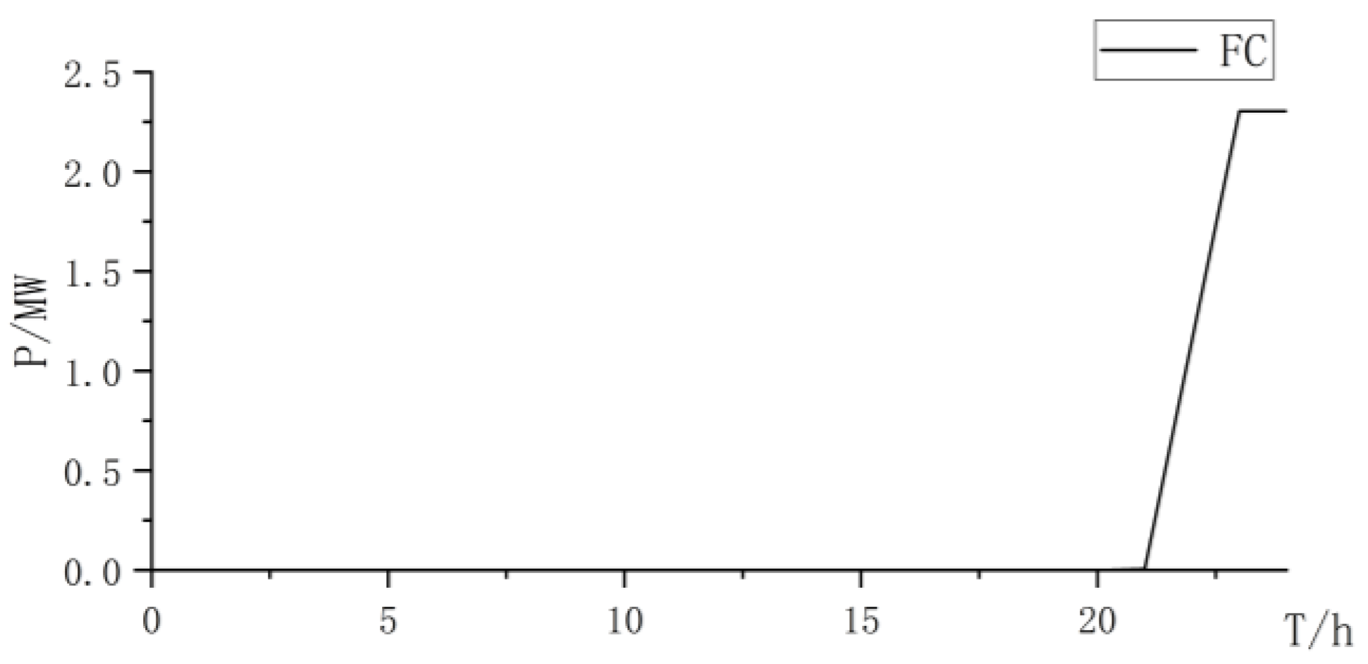
Figure 19.
Power curve of wind power and photovoltaic power and curtailment.
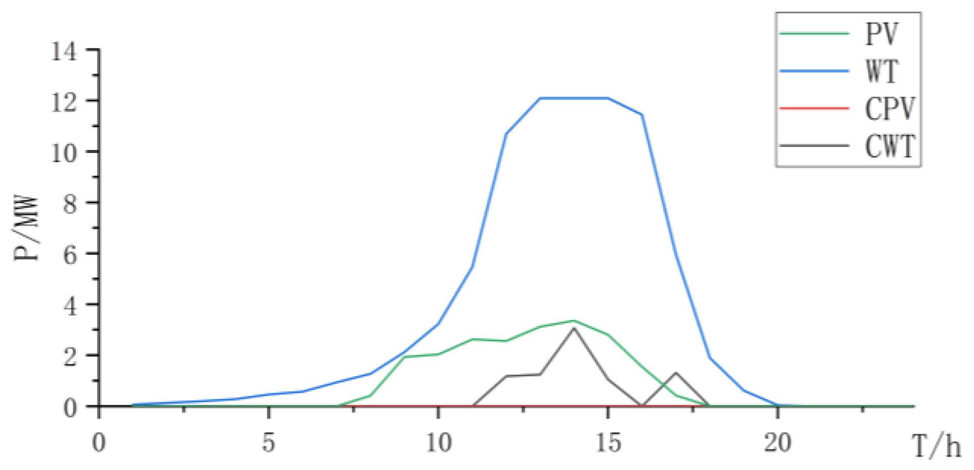
Figure 20.
Collaborative electrolyzer power curve.
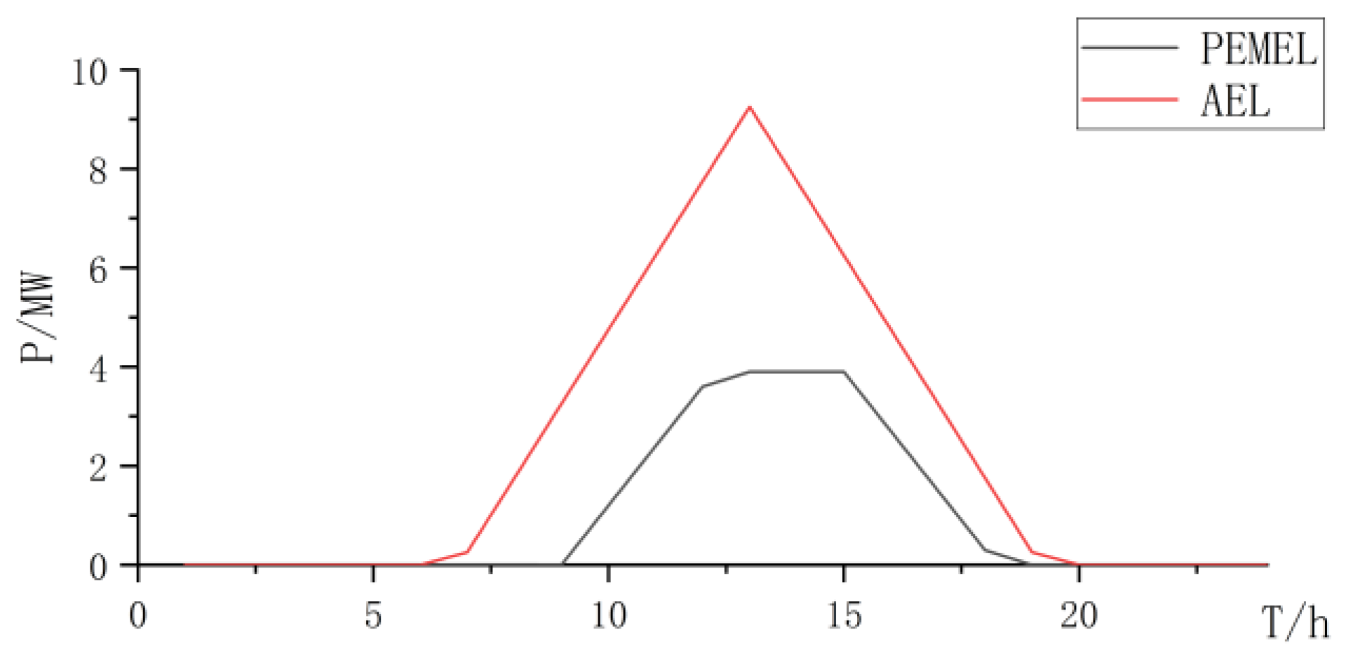
Figure 21.
State changes curve of battery and hydrogen storage.
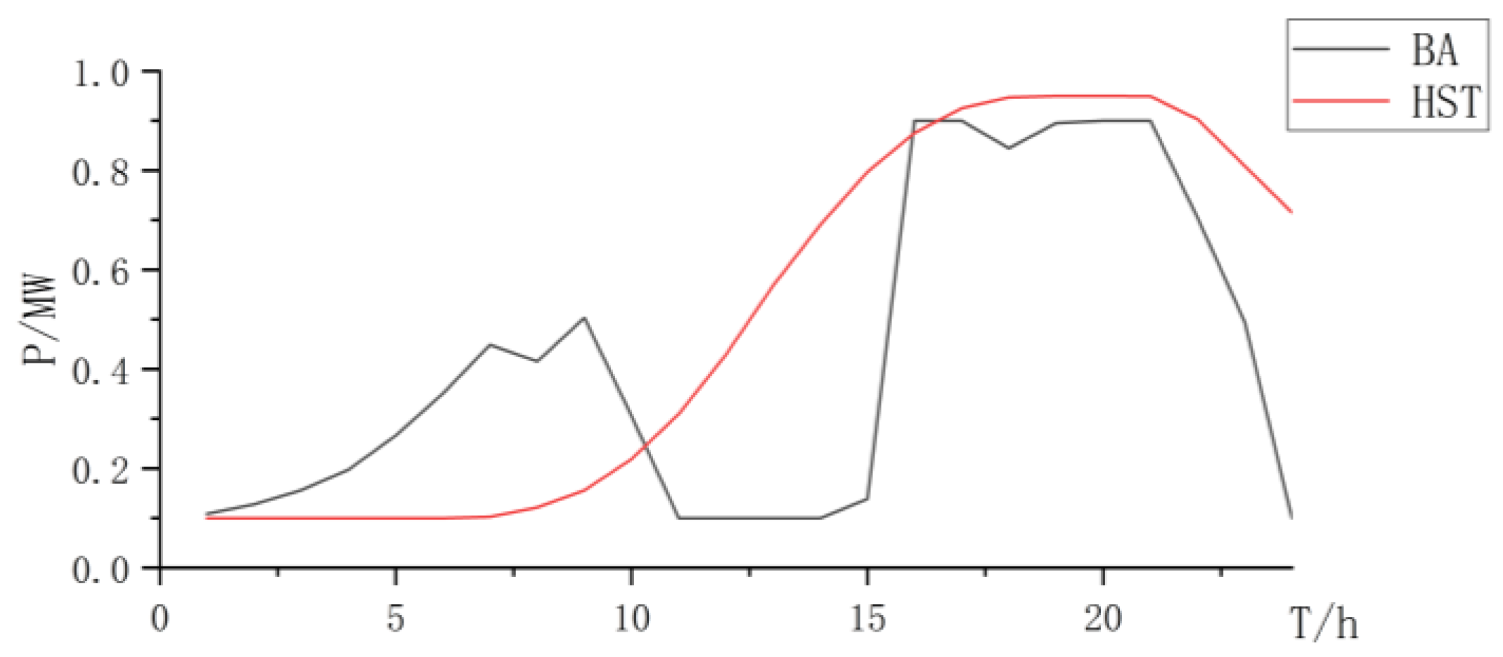
Figure 22.
Fuel cell power curve.

Table 1.
Main parameter values.
| Parameters | Value/CNY | Parameters | Value/CNY |
|---|---|---|---|
| PEMEL/MW | 12,000,000 | Battery/MW | 1,600,000 |
| AEL/MW | 4,000,000 | Fuel cell/MW | 2,000,000 |
Table 2.
Comparison of Optimal Configuration under Conventional Load.
| Co-Electrolysis | PEMEL | AEL | |
|---|---|---|---|
| Cost/×104CNY | 15,291.89 | 16,877.33 | 14,723.43 |
| Num PEMEL | 1 | 7 | / |
| Cap per PEMEL/MW | 0.31 | 0.9 | / |
| Num AEL | 5 | / | 5 |
| Cap AEL/MW | 2.5 | / | 2.5 |
| PV/MW | 3.36 | 3.36 | 3.36 |
| WT/MW | 8.91 | 7.57 | 9.19 |
| BA/MW | 6 | 5.99 | 7 |
| HST/Kg | 1117.64 | 117.64 | 1117.64 |
| FC/MW | 0 | 0 | 0 |
Table 3.
AEL electrolysis curtailment.
| Total/MW | Curtailment/MW | Curtailment Rate |
|---|---|---|
| 82.84 | 13.18 | 15.91% |
Table 4.
Electrolytic electrolysis curtailment.
| Total/MW | Curtailment/MW | Curtailment Rate |
|---|---|---|
| 71.90 | 0.97 | 1.35% |
Table 5.
Collaborative electrolysis curtailment.
| Total/MW | Curtailment/MW | Curtailment Rate |
|---|---|---|
| 80.96 | 11.40 | 14.09% |
Table 6.
Comparison of Optimal Configuration under High Load.
| Co-Electrolysis | PEMEL | AEL | |
|---|---|---|---|
| Cost/×104CNY | 22,124.23 | 22,212.34 | 21,098.20 |
| Num PEMEL | 3 | 9 | / |
| Cap per PEMEL/MW | 1 | 0.97 | / |
| Num AEL | 6 | / | 8 |
| Cap AEL/MW | 2.5 | / | 2.5 |
| PV/MW | 3.36 | 3.36 | 3.36 |
| WT/MW | 12.09 | 10.71 | 13.52 |
| BA/MW | 6 | 6 | 8 |
| HST/KG | 1397.33 | 1397.33 | 1291.38 |
| FC/MW | 2.31 | 2.31 | 1.59 |
Table 7.
Comparison of electrolytic curtailment rates under high-load conditions.
| Total/MW | Curtailment/MW | Curtailment Rate | |
|---|---|---|---|
| PEMEL | 93.12 | 2.23 | 2.40% |
| AEL | 112.12 | 23.71 | 21.14% |
| Co-electrolysis | 102.48 | 7.86 | 11.4% |
Disclaimer/Publisher’s Note: The statements, opinions and data contained in all publications are solely those of the individual author(s) and contributor(s) and not of MDPI and/or the editor(s). MDPI and/or the editor(s) disclaim responsibility for any injury to people or property resulting from any ideas, methods, instructions or products referred to in the content. |
© 2024 by the authors. Licensee MDPI, Basel, Switzerland. This article is an open access article distributed under the terms and conditions of the Creative Commons Attribution (CC BY) license (https://creativecommons.org/licenses/by/4.0/).
Share and Cite
MDPI and ACS Style
Kang, Z.; Liu, S. Research on Capacity Optimization Configuration of Renewable Energy Off Grid Hydrogen Production System Considering Collaborative Electrolysis. Energies 2024, 17, 1962. https://doi.org/10.3390/en17081962
AMA Style
Kang Z, Liu S. Research on Capacity Optimization Configuration of Renewable Energy Off Grid Hydrogen Production System Considering Collaborative Electrolysis. Energies. 2024; 17(8):1962. https://doi.org/10.3390/en17081962
Chicago/Turabian StyleKang, Zhongjian, and Shijie Liu. 2024. "Research on Capacity Optimization Configuration of Renewable Energy Off Grid Hydrogen Production System Considering Collaborative Electrolysis" Energies 17, no. 8: 1962. https://doi.org/10.3390/en17081962
Note that from the first issue of 2016, this journal uses article numbers instead of page numbers. See further details here.