Article

Solution for Post-Mining Sites: Thermo-Economic Analysis of a Large-Scale Integrated Energy Storage System

Group for Energy Storage Technologies, Department of Power Engineering and Turbomachinery, Silesian University of Technology, Konarskiego 18, 44-100 Gliwice, Poland
*
Author to whom correspondence should be addressed.
Energies 2024, 17(8), 1970; https://doi.org/10.3390/en17081970
Submission received: 29 March 2024 / Revised: 16 April 2024 / Accepted: 18 April 2024 / Published: 21 April 2024
(This article belongs to the Collection Renewable Energy and Energy Storage Systems)

Abstract

:
The intensive development of renewable energy sources and the decreasing efficiency of conventional energy sources are reducing the flexibility of the electric power system. It becomes necessary to develop energy storage systems that allow reducing the differences between generation and energy demand. This article presents a multivariant analysis of an adiabatic compressed air energy storage system. The system uses a post-mining shaft as a reservoir of compressed air and also as a location for the development of a heat storage tank. Consideration was given to the length of the discharge stage, which directly affects the capital expenditure and operating schedule of the system. The basis for the analyses was the in-house numerical model, which takes into account the variability of air parameters during system operation. The numerical model also includes calculations of Thermal Energy Storage’s transient performance. The energy efficiency of the system operating on a daily cycle varies from 67.9% to 70.3%. Various mechanisms for economic support of energy storage systems were analyzed. The levelized cost of storage varies, depending on the variant, from 75.86 EUR/MWh for the most favorable case to 223.24 EUR/MWh for the least favorable case.

1. Introduction

A global shift toward zero-carbon technologies seems inevitable despite minor fluctuations related to the geopolitical situation or local discussions of selected social groups. Nevertheless, the general public perception of the challenges that societies will face due to the high-cost requirements of the energy transition seems increasingly favorable. However, it is worth noting that there is a correlation between openness to technological change towards environmentally friendly ones and society’s wealth [1]. This issue is fundamental in countries that rely heavily on fossil fuels, especially coal. The inevitable shift away from coal is forcing a significant focus on reorganizing a considerable part of the industry, which is linked to the reorganization of large groups of workers and the use of the remaining infrastructure. In the case of Poland, Europe’s largest hard coal producer, the number of employees in the entire mining and extraction sector (which includes the extraction of all minerals in Poland) was 123,300 full-time equivalents in 2023. This means a decrease compared to 2017 (130,000 employees) and a significant decrease compared to 2009 (183,000 employees) [2]. Despite significant decreases in production volumes [3], this is still an important area to consider. In the case of China, coal production volume is also decreasing but still significantly higher than the lowest point in 2016. At the same time, these countries’ share of renewables in the energy system is growing significantly. In China, in 2021, there was an increase of nearly 130 GW of capacity, with more than 50 GW coming from PV [4]. In Poland, a country considered to be dominated by hard coal, the share of renewables in the system already exceeded 32% at the beginning of 2022 [5]. These changes raise further challenges, e.g., grid stability, so combining the two mentioned here would be beneficial to make the transition process faster and more realistic.
The aim of this article is to demonstrate the applicability of the in-house numerical model of an adiabatic energy storage system in compressed gases validated experimentally for multivariate thermodynamic and economic analyses. The aim is also to draw the attention of the scientific community to the problem of estimating the potential of systems based on heat storage, especially in the case of heat accumulation in solid porous deposits forcing direct contact of heat transfer fluid with the rock material, which causes both a decrease in gas pressure and progressive imperfections in the flow and heat storage processes. In addition, this article discusses and presents the impact of various financial support mechanisms on the operation of large-scale energy storage systems. Financial support mechanisms appear to be essential for the financial liquidity of energy storage system operators, as their implementation involves large financial outlays. The energy storage systems in operation to date have required the adaptation of extensive floodplains, the construction of dams and barrages, or the leaching of underground salt caverns. It, therefore, appears that one direction for implementing large-scale energy storage systems may be to use existing infrastructure that currently falls under other industries, but adapting them to work with energy storage may be more cost-effective than building a system from scratch. To date, the most widely used large-scale energy storage systems are Pumped Hydro Storage (PHS). Intense growth in installed renewable energy capacity is resulting in a concomitant increase in interest and deployment of energy storage systems of different scales. The European Association for Storage of Energy (EASE) estimates that the demand for installed capacity in energy storage systems in the European Union will be approximately 200 GW by 2030. In 2050, this number is expected to be 600 GW, of which approximately 165 GW is expected to be power-to-X technologies, where electricity is converted into another energy carrier [6]. Energy storage facilities, depending on the characteristics of the technology in question, can act as parameters balancing power grid (preferred technologies with very short response times), price arbitrage (by cyclically buying and selling energy depending on its price) or blackstart in case of system failure [7]. Therefore, there is a market demand for energy storage both from the range of compact battery or electrolyzer installations, but also large-scale PHS or Compressed Air Energy Storage (CAES). Adiabatic compressed air energy storage (A-CAES) is one of the extensions of the basic CAES system concept [8]. This system is based on the introduction of a heat storage subsystem for compression and air regeneration during the system’s discharge stage. This makes it possible to eliminate the combustion of fuel (e.g., natural gas) from the thermodynamic cycle of the energy storage system. The research objectives are presented in Figure 1.
The use of mine infrastructure or underground salt caverns as locations for CAES systems has been widely discussed by researchers. This applies to both diabatic [9,10,11] and adiabatic systems [12,13,14]. However, studies are often based on simple thermodynamic models whose assumptions significantly reduce the accuracy of the calculations. Such assumptions include, for example, the constant efficiency of the TES tank, the absence of the effect of losses to the environment on system performance, or the absence of heat dispersion [15,16,17].
The main novelty of this article is a comprehensive approach to evaluating the potential of an adiabatic compressed air energy storage system. The system concept is based on the author’s European patent [18] for a heat and compressed gas storage system in a post-mining shaft. The calculation is based on the in-house numerical model, which takes into account the imperfection of heat transfer and internal energy dissipation in Thermal Energy Storage (TES), which leads to both energy and exergy losses. In addition, the model has implemented machine operating characteristics—compressors and expanders. These treatments make it possible to accurately estimate the potential for energy storage and predict the generation of energy during system operations. The presented numerical model is a significant development of previous research on the implementation of large-scale energy storage systems. Previously used numerical models used many simplifications, such as fixed machine operating parameters, fixed heat losses within the TES tank, or fixed parameters for gas leaving the TES. These assumptions may have caused large discrepancies between the calculated and actual potential of compressed gas energy storage systems. It should be noted that the developed author’s numerical model for heat flow and storage in TES was validated using the author’s own experimental results. The results of the system analysis were also validated with other previous results obtained from projects focused on A-CAES technology.

2. Materials and Methods

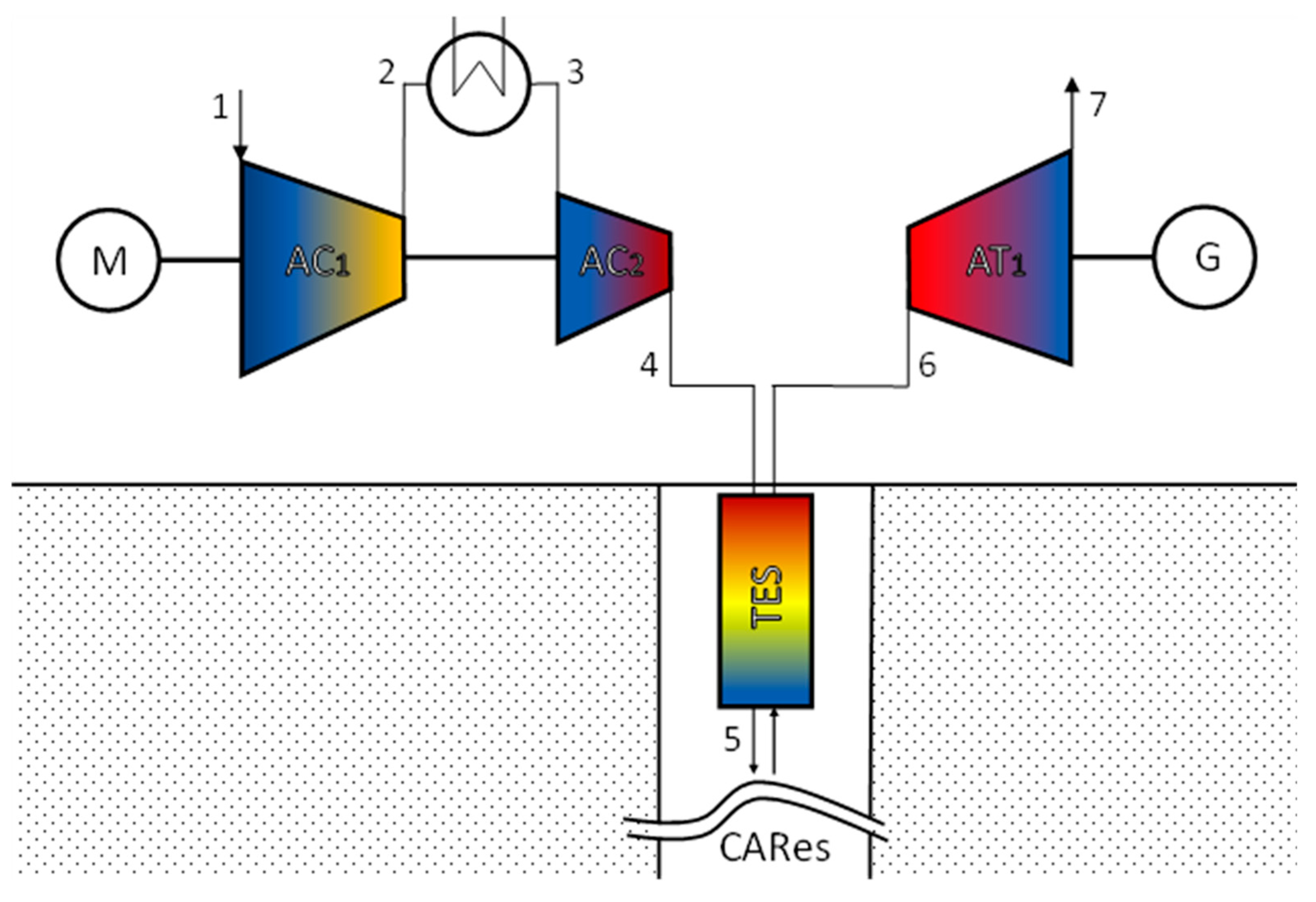
2.1. Adiabatic Compressed Air Energy Storage System Description

A schematic of the system under consideration, along with an indication of the characteristic points, is shown in Figure 2.
The adiabatic compressed air energy storage system in question involves using a vertical, post-mining mine shaft as a compressed air reservoir (CARes). A typical mine shaft in the case of coal mines extracting deep coal seams has a shaft casing with an inner diameter of approximately 9 m. For the purpose of the calculations, the nominal depth of the shaft was assumed to be 1000 m, which corresponds to the depths of reference shafts, for example, in the region of underground mining in Poland and the Czech Republic. Within the mine shaft, it is envisaged to develop a Thermal Energy Storage (TES) to accumulate the heat received from the compressed air leaving the second compressor stage. According to the assumptions, the accumulation material is basalt grit with experimentally determined porosity value of the packed-bed rock deposit [19].
The air is compressed using a two-stage compressor (AC1 and AC2), which is powered by a motor (M) that operates during periods of reduced electricity demand and, thereby, low energy prices. Intercooling of the compressor is carried out in a heat exchanger, and the transferred energy is used in a technological process, which is not the subject of this study. During the energy storage stage, the compressed air remains stored in an underground reservoir. The system’s discharge stage is scheduled for a period of increased electricity demand. During the discharge phase, the air is transferred through the TES reservoir, where it recovers energy potential from the heated porous bed. After flowing through the TES, the air is directed to the expander (AT1).
Unlike other A-CAES concepts, the presented system allows the TES tank to be independent of external conditions. It is assumed that inside the underground infrastructure of mines there is a steady temperature, which increases with depth. Due to the location of the heat tank inside the compressed air reservoir, the pressure differential between the interior of the tank and its surroundings is reduced to less than the air pressure drop across the tank during the charging and discharging stages. In addition, due to the possibility of transferring part of stresses to the shaft structure—the TES tank can be a thin-walled element, which significantly reduces this investment cost.
The estimation of the potential for implementing the energy storage system in a mining region must be preceded by an extensive geological and infrastructural analysis. The condition of the shaft casing and its structure as well as the integrity of the surrounding rocks must be taken into account. Surrounding area stability studies are necessary, as well as measurements of ground subsidence as a result of discontinued mining. Previous studies on the resistance of shaft casing to cyclic pressure changes have confirmed that a post-exploitation mine shaft can be used as a compressed air reservoir [20,21]. Test results performed in the Universal Distinct Element Code (UDEC) indicated negligible local displacements in the casing structure. It should be noted that a mine shaft must also meet minimum geometric dimension criteria, as the volume of the shaft directly affects the energy storage capacity. It has been shown that decreasing the diameter of the TES tank leads to an increase in the energy storage potential, but at the same time increases the air pressure loss. In Figure 3 the structure of the TES installation located in the post-mine shaft is shown.

2.2. Thermodynamic Model

The numerical model was compiled originally using MATLAB 2022b software with the Coolprop 6.6.0 add-on implementing the possibility of calculating real gas parameters. The parameters are determined using the real gas model proposed by Lemmon et al. [22] whose applicability is in the range of gas temperature from 60 K to 2000 K and its pressure up to 2000 MPa. The authors determined that the estimated uncertainty of the air density up to 873 K and a pressure of 70 MPa is 0.1% of the value, and the heat capacity is 1%. Above this point, the uncertainty of the density value is 0.5% and increases to a value of 1% at 2000 K and 2000 MPa. The numerical model consists of 4 interdependent components, the results of which cascade to determine certain assumptions in other blocks of the model. The numerical model of the A-CAES system includes:
  • A mechanical model that, based on technical standards and preliminary assumptions of system pressure limits, as well as maximum allowable air temperatures, allows determining the minimum recommended parameters of the TES tank [23].
  • A thermodynamic model of the compression and expansion system, which uses the dynamic characteristics of these devices that depend on the ratio of pressures and temperatures to nominal parameters [24]. The characteristics allow the determination of instantaneous internal efficiencies. The thermodynamic model, along with the main relationships, is discussed in detail in Bartela et al. [25].
  • A dynamic model of the charging, heat storage, and discharge stages of the TES tank, which operates in parallel with the thermodynamic model of the compression and expansion system, allows calculation of air pressure drop, as well as dynamic calculation of air and rock material temperatures inside the heat storage tank. The numerical model also includes calculations of heat loss to the environment, as well as heat accumulation in the tank wall and insulation [26].
  • An economic model that allows the selected system operating scenario to be adjusted to the accepted data in the range of time-varying energy prices.
The dynamic model of the TES tank was based on the Non-Equilibrium Thermal Model, in which the rock deposit is treated as parallel interacting zones: the rock zone and the fluid zone. The energy conservation equation for the fluid zone is presented in Equation (1) and for the rock zone in Equation (2):
t ε ρ f E f + · v ρ f E f + p = · ε k f T f + h f s A f s ( T s T f ) ,
t ( 1 ε ) ρ s E s = · ( 1 ε ) k s T s + h f s A f s ( T f T s ) ,
where ε is the porosity of the rock deposit defined as the ratio of the volume of the fluid to the volume of the rock material in the heat reservoir, v is the velocity of the fluid, ρ s and ρ f are the density of the rock and fluid, respectively, p is the pressure of the fluid, T s and T f are the temperature of the rock and fluid, respectively, k s and k f are the heat conduction coefficient of the rock and fluid, respectively, and A f s is the heat transfer area defined as 6 · 1 ε / D p where D p is the diameter of the rock bed particle. The convective heat transfer coefficient between the fluid and rock material h f s determines the intensity of heat transfer between the media and is defined as:
h f s = N u f s · k f D p ,
where N u f s is the Nusselt number. The article by Ochmann et al. [27] extensively discusses and evaluates the selection of one of the correlations used for the Nusselt number for the slender heat storage case under study. The selected correlation is presented in Equation (4) [28].
N u f s = 2 + 1.1 · R e 0.6 · P r 1 / 3 ,
The applicability of this correlation was proven for the laboratory bench used to validate this numerical model. The best match between empirical and computational results is obtained in the range of 10 3 < ( P r 1 / 3 · R e 0.6 ) 2 < 10 4 for spherical elements where P r is the Prandtl number and R e is the Reynolds number. Heat penetration inside the tank wall volume is also calculated. The heat transfer coefficient h f w between these phases is defined analogously to h f s (Equation (3)); however, a different correlation of the Nusselt number is used. The heat penetration coefficient for the tank wall is defined as [29,30]
h f w = N u f w · k f D p ,
where the Nusselt number N u f w is determined by the relation [31].
N u f w = 0.0835 · R e 0.91 ,
The applicability of this correlation has been proven for the range of the N ratio of the TES diameter to the bed particle diameter 4 < N < 30 . The laboratory bench is characterized by N equal to 13.31. The chosen correlation for the Nusselt number has been extensively discussed and numerically compared with others available in the literature by Wehinger and Scharf [32]. The air pressure drop along the length of the heat accumulator is calculated using the Ergun equation [33]:
p L = 150 · μ f D p 2 · 1 ε 2 ε 3 · v + 1.75 · ρ f D p · 1 ε ε 3 · v 2 ,
where μ f is the dynamic viscosity of the fluid.
The number of TES segments n required to accumulate heat during the charging stage of the system was calculated from the formula:
n = 1.2 · V T E S _ n · ρ b · ( 1 ε ) · c p b · T m a x T m i n 0 τ c m a ˙ · h 4 h 5   d τ ,
where V T E S _ n is the volume of TES segment assuming a constant diameter D T E S and segment height H T E S _ n , T m a x is the air maximum temperature during charging stage at point 4, T m i n is the air minimum temperature in the system, m ˙ a is the air mass flow during charging stage h 4 and h 5 are the enthalpies of air at points 4 and 5, respectively, and c p b is the heat capacity of basalt.

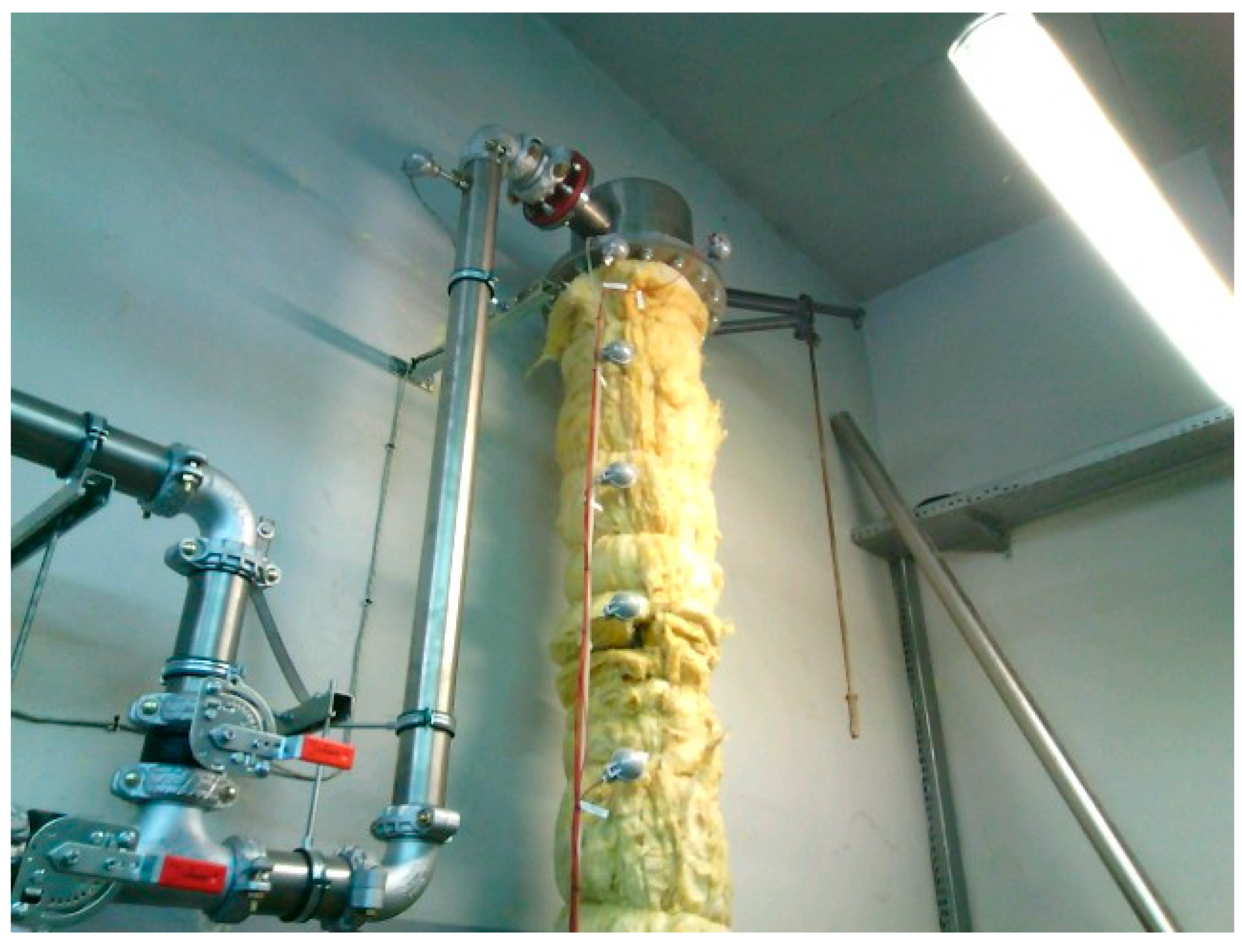
2.3. Laboratory Stand and Thermal Energy Storage Investigation

The basis for the development of system modeling is the research performed on a laboratory stand involving the vertical basalt-filled heat storage tank [34]. The tank is supplied using temperature-controlled, peri-atmospheric pressure air. Thanks to the valve system, it is possible to charge the storage tank from the top and discharge it from the bottom, which corresponds to the operating characteristics within the A-CAES system built in the mine shaft. The TES tank is 3 m high, and its diameter is 0.219 m. The total volume of the heat storage tank is approximately 0.1 m3. The temperature of the rock deposit is registered using ten resistance temperature detectors located along the axis of the storage tank. In addition, the slenderness of the laboratory TES tank corresponds to the geometrical characteristics of a large-scale system possible to be installed in a mine shaft. As a consequence, the cross-sectional area of the tank (which in the real scenario is limited by the diameter of the shaft) is reduced, while its length is increased. The laboratory stand was presented in Figure 4.

2.4. Assumption for Analysis

As mentioned, a real gas model was used to increase the accuracy of the numerical model. In addition, the dynamic characteristics of the compressor and air expander were assumed during the calculations. Variable thermophysical parameters of the rock material, structural steel and thermal insulation were implemented in the numerical model [35]. The rock material was tested using a C-Therm TCi device with accuracy and precision of 5% and 1%, respectively. The prepared samples correspond to the material used on the laboratory bench. Through testing, it was possible to obtain values of basalt’s thermal conductivity and heat capacity.
The assumptions for the adopted calculation analysis are presented in Table 1.

3. Results

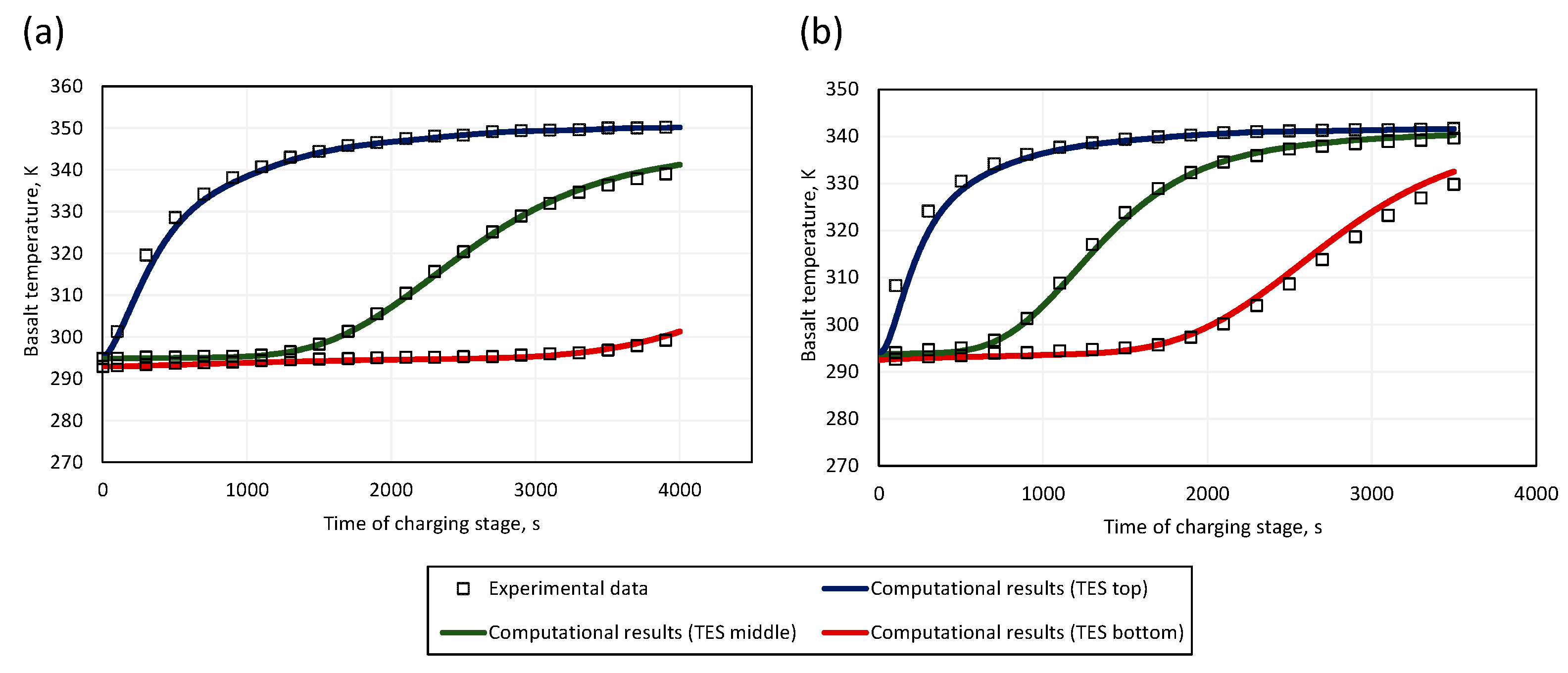
3.1. Numerical Model Validation

The numerical model was validated against the experimental data. In order to examine the flexibility of the numerical model, a comparison was made with an experimental series with an insulated storage tank (Figure 5a) and a storage tank without thermal insulation (Figure 5b).
In both cases, the simulation results correspond to the experimental data, also falling within the maximum limits of measurement error. The largest deviations were noted for the intense temperature rise in the upper area of the TES tank, which may be due to the location of the resistive temperature sensor in relation to the tank’s air inlet, which was not represented in the numerical model, and assumed fully developed inlet flow.
The results of the thermodynamic analysis of the adiabatic CAES system were validated using system data presented by Zunft [36]. His work presents the results of a preliminary analysis of one of the solutions considered in the realization of the ADELE project [17]. The system configuration was analogous to the one discussed in this paper; however, the heat storage tank was an above-ground structure made of prestressed concrete, and the compressed air reservoir was a salt cavern with a volume of approximately 360,000 m3. The minimum and maximum air pressures in the reservoir were equal to 5 MPa and 7 MPa, respectively. The maximum air temperature after the second stage of the compressor was 600 °C, and the air temperature in the reservoir was equal to approximately 50 °C. The results of the comparative analysis are shown in Table 2.
The results of the thermodynamic analysis show high convergence with the operating parameters of the basic model of the A-CAES system studied in the ADELE project. Approximately 5% difference was observed in the compressor power, which may be the result of the assumed nominal compressor efficiency value and differences in the relationship between temperature and pressure of the medium and compressor efficiency.

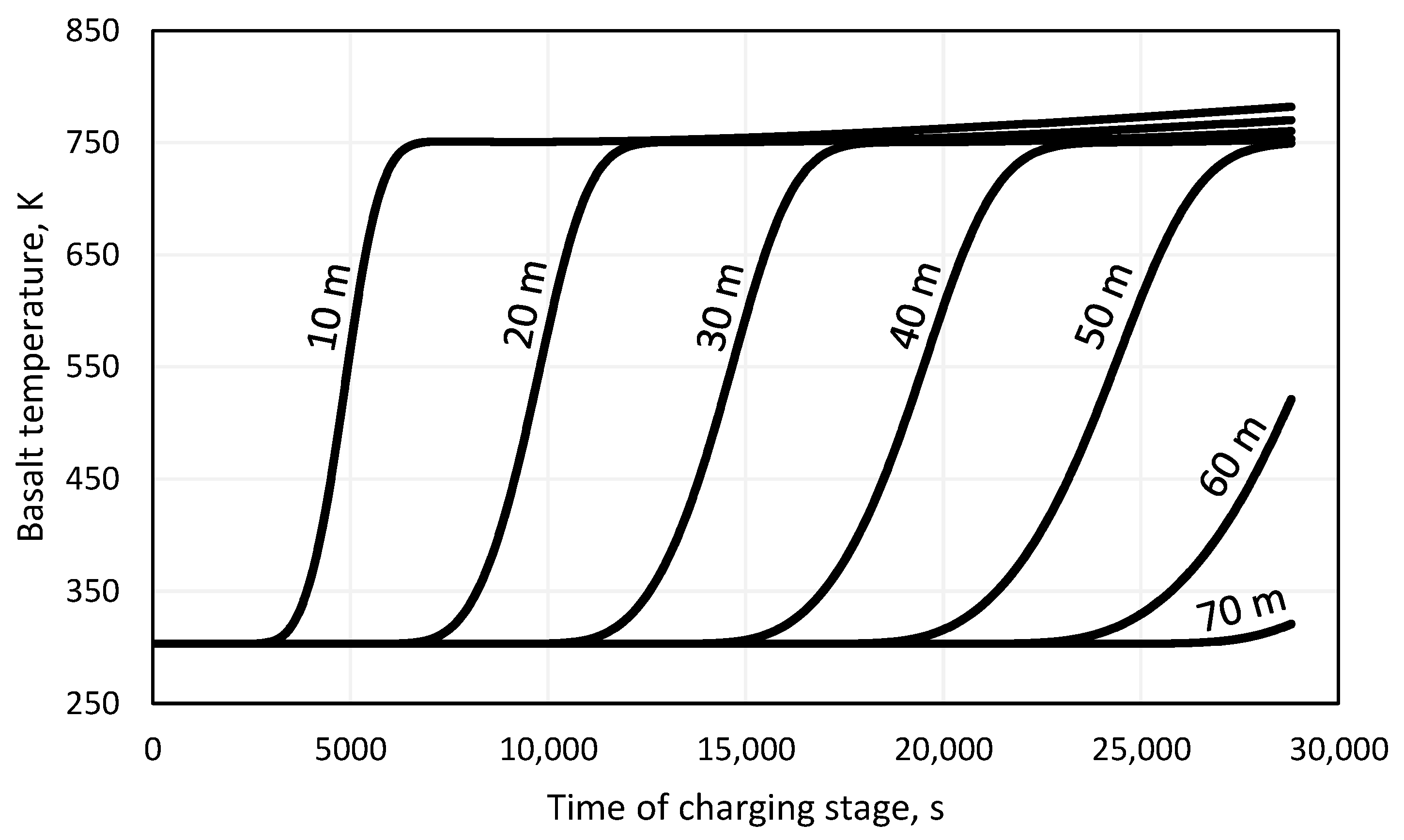
3.2. Results of Thermodynamic Analysis

Preliminary results obtained from the mechanical and thermodynamic model allowed determining the final volume of the compressed air reservoir, which was 62,115 m3 with a TES tank of 70 m in length and a flow diameter of 5 m. The thickness of the tank wall’s steel was estimated at 0.015 m, assuming an adequate safety allowance for corrosion. Assuming a difference in air pressure in the reservoir between the beginning and end of the charging stage, the charging air flow rate was calculated to be 59.82 kg/s. The duration of the storage and discharge stage was considered according to six cases, the details of which are shown in Figure 6.
The variable time of the energy storage stage makes it possible to adjust the system operation schedule to the most favorable time intervals during the day in terms of electricity prices. It was assumed that during cyclic operation, the amount of heat remaining in the TES tank after the discharge stage is negligible and does not affect subsequent system operation cycles. However, the duration of the storage stage measurably affects the energy and exergy efficiency of the TES tank and the entire energy storage system. Because of the resulting temperature gradient of the basalt, a natural heat dispersion effect is observed through the flow of heat from higher temperature zones to lower temperature zones. The reduction in the stored energy potential is also affected by the heat flow effect through the tank wall and insulation and its accumulation in these elements, as well as irreversible losses to the environment. Figure 7 presents the increase in basalt temperature at selected points during the charging stage, counting from the inlet to the TES tank.
As assumed, the temperature of the rock material did not exceed the permissible value of 795 K, while the temperature of the charging air was not constant during the charging stage due to other than nominal compressor operating parameters. Martin et al. [37] studied the thermophysical parameters and strength of basalt and quartzite in long-term, high-temperature heat storage. No significant structural changes were shown in the basalt stones after testing at 560 °C, and no cracks or cavities were observed. As indicated in Figure 7, despite the use of a 20% volume allowance for the accumulation material relative to its minimum amount necessary to store the heat of compression (Equation (8)), an increase in the basalt temperature in the lower part of the storage tank was noted. This indicates the occurrence of an irreversible physical outlet loss to the volume of the compressed air reservoir. In Figure 7, it can be noted that from 50 m to 70 m a temperature gradient of approximately 21 K/m was recorded for the rock material, where at 0–50 m the gradient is only approximately 1 K/m. Table 3 presents the characteristic temperatures of the rock material in relation to the length of the energy storage stage. A value of “0” is specified for the end of the charging stage of the system.
As shown, as the duration of the storage stage increased, a progressive effect of natural energy dispersion inside the heat storage tank was noted. After 12 h of this stage, the maximum temperature of the rock material decreased by 0.94 K, and the minimum temperature increased by 1.56 K. It is worth noting that during the entire cycle of TES tank operation, heat loss to the tank wall volume and the environment was taken into account. The obtained temperature distribution of the rock material was, therefore, the result of the energy loss and exergy components of the heat storage process in the rock material.
The need to use the accumulated compressed air during the discharge stage, which is indicated in Figure 6, carries with it the need to increase the mass flow rate of regenerated air. Thus, the scale of the expander and investment costs increase; however, its nominal parameters also depend on the air pressure drop at the TES tank. According to Ergun’s equation, the value of the air pressure drop depends on, among other variables, the flow velocity and the temperature- and pressure-dependent density of the fluid. Figure 8a shows the values of air pressure drops on the TES element of the studied system variants along with the calculated air mass flow rates during the discharge stage. Figure 8b shows the temperature of the regenerated air, which is directed to the gas expander.
To present the results more clearly, Figure 8a excludes Variant 6. This variant, during the 3600-s discharge stage, is characterized by a drop in air pressure of 1468 kPa at the beginning of this stage and 910 kPa at the end. In each of the studied variants, a decrease in the tested value was registered, which is related to the change in air density resulting from the progressive discharge of the heat storage tank. For variant 1, the nominal pressure of the expander was 6.76 MPa, when for variant 6, this value was 5.61 MPa. Figure 8b shows that as the duration of the discharge phase increases, the period of the intense drop in the temperature of the regenerated air increases. Regardless of the variant studied, the air temperature at the end of the discharge stage is relatively similar. Table 4 presents the consumption and production of electricity and round-trip efficiency by case.
As assumed, the energy consumption during the charging stage is equal in each of the studied cases (see Figure 6). Electricity production depends on the nominal pressure of the expander, the value of which decreases as the air pressure drop on the TES increases. The energy efficiency of the studied system was determined to be approximately 67–70%, which is in line with the A-CAES systems analyzed so far in the literature [38].

3.3. Economic Assessment of the A-CAES System Using Post-Mine Shaft

For economic calculations, energy prices in 2022 in Poland were taken as a reference. Poland is experiencing intensive growth in the share of renewable energy sources in the national energy mix. In 2022, the share of RES in national production reached 19.1%, almost doubling this value compared to 2016 [7]. This is similar to the value achieved in France and Belgium (23.4% and 22.8%, respectively), but significantly different from Germany (49.2%), Spain (44.7%), or Lithuania (78.8%). Energy prices on the Polish market on an annual basis are presented in Figure 9a. The characteristic values per day are presented in Figure 9b.
The average hourly energy price used in the calculations ranges daily from 137.26 EUR/MWh to 236.65 EUR/MWh. During the summer, the highest energy prices were recorded, reaching 771.00 EUR/MWh. The high energy prices were caused by the problem with the availability of hydrocarbons used in the energy industry as a result of the unstable situation in the middle-eastern region in Europe. Figure 10 presents a summary of the average hourly energy prices with the adopted scenarios for the operation of the A-CAES system.
The operation of the air compressors was scheduled for the night-morning valley, during which there is the longest 8-h period of lowest energy prices. During the charging stage, there is a continuous increase in energy consumption, which is related to the increase in pressure in the compressed air reservoir and, as a result, the operation of the compressors at a non-nominal point. The discharge stage, during which energy is sold to the grid, is scheduled for the evening demand peak, which begins approximately 5 p.m. and ends approximately 11 p.m. As indicated in Figure 10, in each scenario there was a decrease in the value of energy generated during system operation, which is related to a decrease in both air pressure and temperature, which has a direct impact on the performance of the gas expander. An additional 7th case was also investigated, in which the discharge stage lasts 1 h (as in the case of variant 6), but the time of this stage falls on the hour with the highest energy price during the day. This case corresponds to a situation in which the scenario for the operation of the energy storage system is determined dynamically based on day-ahead market data.
The economic evaluation of the considered cases was carried out using the following methodology. Financial flows C F τ were defined as:
C F τ = S + A C J K O & M + L + A t ,
where S is the income, J is the investment cost [40], L is the system liquidation value, A C is the avoided costs, and A is a depreciation.
Income S is defined as:
S = i = 1 i = 8760 C e l , d c h i · E e l , E x i ,
where E e l , E x i is the expander energy production in the i-th hour of the year; C e l , d c h I is the sale price of energy in the i-th hour of the year during the discharging period.
Investment cost were calculated as:
J = J C + J E x + J T E S + J b + J O ,
where J C is compressor cost, J E x is expander cost, J T E S is TES system cost, J b are building costs and J O are other costs (e.g., pipelines, control systems).
Operating and maintenance costs K O & M consist of fixed and variable parts as well as the cost of purchasing electricity, it can be written using the equation:
K O & M = K O & M f + K O & M v ,
where K O & M f and K O & M v are fixed and variable part of operating costs and K e is cost of purchasing electricity, respectively.
In order to calculate the value of fixed and variable costs in subsequent years of the system operation, the unit indicator of fixed operation and maintenance costs— k O & M f —as well as the unit indicator of variable operating and maintenance costs— k O & M v —were assumed. The values of individual costs were calculated from the following dependencies:
K O & M _ F = k O & M f · N e l , E x + A ,
K O & M v = k O & M v · E e l , E x + i = 1 i = 8760 C e l , c h i · E e l , C i ,
where N e l , E x is power of expander and E e l , E x is amount of electricity produced, E e l , C i is the compressor unit energy consumption during the i-th hour of the year, C e l , c h i is the purchase price of energy in the i-th hour of the year during the charging period.
The cash flows determined from the Equation (13) were used to determine the levelized cost of storage (LCOS). LCOS was determined from the equation [41,42]:
L C O S = J + τ = 0 τ = N K O & M + L + A 1 + r τ τ = 0 τ = N i = 1 i = 8760 E e l , E x i 1 + r τ ,
where r is the discount rate and τ is the time in years (0 means the year of construction start).
For the examined case of using the A-CAES energy storage system with the use of a post-mining shaft, an economic analysis was also carried out. The economic analysis was carried out by using the Net Present Value (NPV), which is defined by the equation:
N P V = τ = 0 τ = N C F t 1 + r τ ,
where N is the last year of system operation time. The evaluation of the profitability of the investment was made using the Net Present Value ratio ( N P V R ) defined as:
N P V R = N P V J ,
If the N P V R value is > 0 , then the investment is profitable over its planned lifetime. In the case of N P V R = 0 , the investment is economically neutral. When N P V R < 0 the investment is unprofitable.
The European Commission is recommending the implementation of support mechanisms for energy storage systems to improve energy security in the states [43]. Intense development of RES, advancing age and declining efficiency of existing conventional energy sources negatively affect the flexibility of the power system. These solutions can be described as:
  • Permission to use existing infrastructure—regulations are needed to transfer post-mining infrastructure or salt caverns used as fuel storage to implement energy storage systems. There is a need to develop a methodology for determining the safety and operation of these structures. In addition, it is also possible to convert existing conventional systems to increase their flexibility. Such a conversion can include the installation of a TES tank [44,45].
  • Admission to participate in the balancing market—allowing energy storage systems into the balancing market for power grid parameters will increase the viability of these systems. In some European countries, storage systems are already allowed to participate in this market. The grid operator determines the time and period of activation of the system (both generation and consumption of energy) thanks to which the differences between demand and generation are reduced.
  • Tax exemptions for the purchase of electricity—allow to increase the profitability of investments in energy storage systems and faster payback time. The discount covers the period of energy purchase while the system is charging.
  • Implementation of dual-commodity energy exchange—a mechanism that involves rewarding the energy storage system operator both when energy is produced according to grid demand and when the system is ready to energy production. The fact that the energy storage system remains in the system operator’s reserve resources makes it possible to protect the grid during periods of high load variability, planned shutdowns of other systems or failures.
  • Implementation of a virtual power plant—a system that allows the optimization and interaction of interconnected energy systems. This enables more efficient planning of operating schedules, as well as optimal management of surplus energy.
The scope of this article examines different configurations of support mechanisms. In addition to the profit in the form of electricity sales at the peak of demand, the algorithm assumed that due to the use of the post-mine infrastructure together with the mine shaft, the costs of liquidation of the mentioned elements were avoided. The author of the article [46] described legal and economic aspects of the mine liquidation process hard coal in Poland. In his article, the author presents examples of unit costs of decommissioning mine facilities as well as an algorithm for estimating the costs of decommissioning 1 million Mg of the mine’s production capacity. For the purposes of this article, the average value of mine liquidation presented in [46] was used. In addition, due to the data origin date (2009), an increase in the inflation rate of 20% was assumed in relation to the current conditions. Table 5 shows adopted assumptions for economic analysis.
The economic analysis using the LCOS indicator includes six different variants for the construction and operation of an adiabatic CAES system. Variant 1 defines a situation in which the energy storage system operator cannot count on legislative support from the reduction in energy purchase rates by the value of the tax, and does not function as an island installation with the RES system, forcing the cyclical purchase of energy from the grid. In addition, this option does not take into account the avoided costs of decommissioning a mine shaft. The second variant assumes an exemption from tax on the purchase of electric energy, the value of which is indicated in Table 6. Variants 5 and 6, due to their operation under an island RES system and free electricity, exclude the need to purchase power from the grid. The configurations of all the variants considered are shown in Table 6.
Figure 11 shows the results obtained for individual variants of the adopted assumptions for the calculation of the LCOS value.
The analysis shown in Figure 11 indicates that the most cost-effective scenario for all cases is the option in which electricity during the charging stage of the system is free, and the avoided costs take into account the potential cost of decommissioning the mine shaft. The LCOS value ranges from 75.86 EUR/MWh for case one and 223.24 EUR/MWh for cases six and seven. For the last two cases, all LCOS values are equal due to the definition of this indicator and only differences in the daily operation of these systems. Similar calculations of the LCOS index for adiabatic CAES systems are presented in [50]. The author of the article determines the LCOS values for various technological solutions enabling energy storage. For adiabatic CAES systems, the author received similar values between 70 and 110 EUR/MWh, while the lowest value of the LCOS index was obtained for pumped-storage hydroelectricity (PSH) at the level of 70–90 EUR/MWh.
The value of the NPV parameter for Case 1 and the most favorable variant 6 amounted to more than EUR 79 million after 50 years of system operation (free electricity and included the avoided costs of decommissioning the mine shaft). In comparison, for this variant in Case 6 and Case 7, the NPV was EUR 19,131,147 and EUR 31,009,165, respectively. The value of the NPVR index was 0.15 for Case 6 Variant 6, and 0.26 for Case 7 Variant 6. CAPEX for Case 1 was more than EUR 50 million, and for Cases 6 and 7 more than EUR 118 million, as a result of the power of the expander used. NPV values indicate that an installation using a lower-power expander with a longer expansion time is more cost-effective. On the other hand, an installation with more power and a shorter expansion time yields higher annual profits and will be the more profitable one if it has a longer life. This indicates that it is extremely important to align the energy storage system operation plan with grid conditions and energy prices planned in advance. It follows that extending the discharge phase (as in cases 1–5) reduces the flexibility of the energy storage system. On the other hand, extending the discharge time reduces the financial investment, which at the same time lowers the cost-effectiveness threshold for implementing an energy storage system. Estimating the actual potential of a proposed energy storage system strongly depends on its specific location and the adaptation of local state laws to the degree of demand for energy storage systems. Even in the countries of the European Union, which has well-defined development goals even up to 2050, there are significant discrepancies regarding the process of contracting energy storage systems and their admittance to the realization of system services other than price arbitrage. The CAES system, due to its time to start up and reach full power (approximately 10 min [51]), can perform a number of roles in support of the national power system. In addition to the aforementioned price arbitrage, which at the same time supports the reduction in valleys and peaks in energy demand and production, a system with these characteristics qualifies as a manual Frequency Restoration Reserve (mFRR) system for regulating network parameters. Energy storage systems also provide protection for the power system in the event of widespread grid failure and the need to restart network equipment, known as blackstart. Depending on the legislation, some of the ancillary services for energy storage are free or paid, and mandatory or optional. In addition, there are also a number of initiatives aimed at increasing the cooperation of national power systems, which is also an opportunity to increase the cost-effectiveness of energy storage operations—examples of such efforts are the Manually Activated Reserves Initiative (MARI) [7] or Trans European Replacement Reserves Exchange (TERRE) [7] projects, which were launched in 2017 and 2016, respectively, with the aim of launching international joint platforms for the exchange of compensating energy between countries in continental Europe.

4. Conclusions

This article presents the results of dynamic modeling of the operation of an adiabatic energy storage system in compressed air. The model includes dynamic modeling of the gas compression and expansion processes, as well as heat accumulation and storage in the Thermal Energy Storage. A multivariate analysis from the range of expansion stage scheduling made it possible to determine the efficiency of the system’s operation cycle, as well as to perform an economic analysis of each case.
  • The in-house numerical model demonstrates very high accuracy in both the modeling of the Thermal Energy Storage reservoir and the adiabatic Compressed Air Energy Storage system, which has been proven experimentally and comparatively with the analytical results of other studies.
  • The maximum round-trip efficiency was 70.32% for the system, whose discharge stage length was the longest among those tested, lasting 6 h. The lowest efficiency was achieved for the shortest discharge stage lasting 1 h and was 67.91%. The length of the energy storage stage was also shown to affect the system’s cycle efficiency. The efficiency of the system is affected not only by heat loss to the environment from the TES tank, but also by internal heat dispersion in the rock material and tank walls.
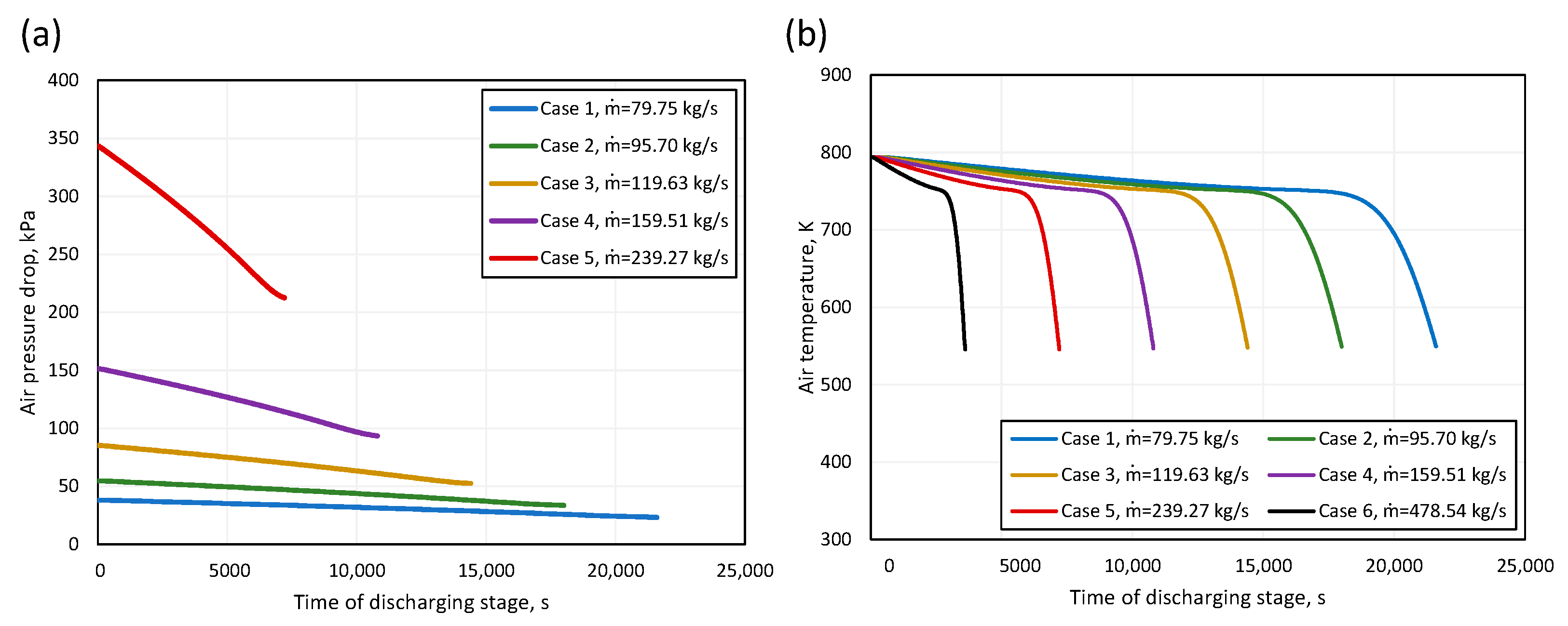
  • Reducing the time of the discharge stage results in an increase in the value of the air pressure drop on the heat storage tank. For the case of a discharge stage lasting 6 h, the value did not exceed 45 kPa. For a one-hour discharge stage, the maximum value of the pressure drop was 1468 kPa. During the discharge stage, a continuous decrease in the temperature of the regenerated air is observed.
  • The economic analysis performed for the least favorable variant of adiabatic CAES system shows the LCOS value equal to 223.24 EUR/MWh. The LCOS value varies significantly depending on the assumptions made for economic calculations. The most favorable LCOS equaled 75.86 EUR/MWh. It was achieved for the case with the smallest investment outlay, which was the result of the longest discharge phase and thus the smallest capacities of the tested expander. In addition, in this case, the electricity was free, reflecting the case of operating the system as an integrating RES with the power grid.
  • Legislative support has been shown to be strongly relevant to the viability of an energy storage system. The difference in LCOS for the option without the energy purchase tax was in each case approximately 15 EUR/MWh lower than in the case where the system operator is forced to purchase energy at the full market amount.
  • Future studies should focus on setting a roadmap for implementation of large-scale systems to determine the scopes of legislative support. In addition, the presented numerical model can be used to determine the optimal parameters of the TES tank in terms of dimensions, type of storage material, as well as type of walls and thermal insulation.
  • Future research should focus on the development of a consistent methodology to determine the potential for large-scale energy storage at a given location of post-mining infrastructure. The methodology should cover not only the local energy storage needs of the grid, but also infrastructure strength aspects such as rocks stability and composition, the condition of the shaft casing and other infrastructure, as well as locally occurring water and gas leaks.

Author Contributions

Conceptualization, J.O. and Ł.B.; methodology, J.O., Ł.B., M.J. and W.U.; software, J.O. and K.R.; investigation, J.O., M.J., K.R. and S.R.; resources, J.O. and S.R.; writing—original draft preparation, J.O.; writing—review and editing, M.J. and W.U.; supervision, Ł.B.; funding acquisition, J.O. and Ł.B. All authors have read and agreed to the published version of the manuscript.

Funding

The work presented in this paper was performed as part of the HESS project (Hybrid energy storage system using post-mining infrastructure) grant no. 101112380 supported by the EU RFCS.

Data Availability Statement

The raw data supporting the conclusions of this article will be made available by the authors on request.

Conflicts of Interest

The authors declare no conflicts of interest.

Abbreviations

The abbreviations, symbols or subscripts used in this text are detailed below:
Abbreviations
A-CAESAdiabatic compressed air energy storage
CAESCompressed Air Energy Storage
CAPEXCapital Expenditure
EASEThe European Association for Storage of Energy
LCOSLevelized cost of storage
MARIManually Activated Reserves Initiative
mFRRmanual Frequency Restoration Reserve
NPVNet Present Value
NPVRNet Present Value ratio
PHSPumped Hydro Storage
RESRenewable Energy Sources
RMSERoot mean square error
TERRETrans European Replacement Reserves Exchange
TESThermal Energy Storage
UDECUniversal Distinct Element Code
Symbols
Aarea, m2
ACair compressor
Acavoided costs, EUR
ATair expander
brange of measuring device
CARescompressed air reservoir
CFcash flow
cpheat capacity at constant pressure, J/kgK
Ddiameter, m
Eenergy, J
eenergy price. EUR/MWh
hheat transfer coefficient, W/m2K
henthalpy, J/kg
Jinvestment cost, EUR
kheat conductivity coefficient, W/mK
KOperating and maintenance costs, EUR
Llength, m
Lliquidation value, EUR
Mmotor
mmass flow, kg/s
NTES diameter to particle diameter ratio, -
nnumber of TES segments, -
NuNusselt number, -
ppressure, Pa
PrPrandtl number, -
ReReynolds number, -
SIncome, EUR
ttime, s
Ttemperature, K
vvelocity, m/s
Vvolume, m3
Greek symbols
ɛporosity, -
ϴuncertainty
μdynamic viscosity, Pa·s
ρdensity, kg/m3
σexperimental standard deviation
Subscript
aair
Atype A uncertainty
avaverage
bbasalt
Btype B uncertainty
ffluid
fsfluid-solid
fwfluid-wall
i_cenergy consumption/energy price
i_penergy production/energy price
maxmaximum
minminimum
O&M_Ffixed operation and maintenance costs
O&Mffixed part of operating costs
O&Mvvariable part of operating costs
pparticle
ssolid
TES_nnominal TES volume

References

  1. Thomas, M.; DeCillia, B.; Santos, J.B.; Thorlakson, L. Great expectations: Public opinion about energy transition. Energy Policy 2022, 162, 112777. [Google Scholar] [CrossRef]
  2. Statistics Poland. Available online: https://stat.gov.pl/ (accessed on 1 July 2022).
  3. Global Economic Data. Available online: https://www.ceicdata.com (accessed on 1 July 2022).
  4. Renewable Energy Market Update—May 2022. Outlook for 2022 and 2023. Iea Full Raport, May 2022. Available online: https://www.iea.org/reports/renewable-energy-market-update-may-2022 (accessed on 2 September 2022).
  5. Power Installed and Achievable in National Power Plants. Available online: https://www.pse.pl/dane-systemowe/funkcjonowanie-kse/raporty-roczne-z-funkcjonowania-kse-za-rok/raporty-za-rok-2021 (accessed on 9 September 2022).
  6. European Association for Storage of Energy. Available online: https://ease-storage.eu/ (accessed on 17 February 2023).
  7. European Association for the Cooperation of Transmission System Operators for Electricity. Available online: https://www.entsoe.eu/ (accessed on 17 February 2023).
  8. Courtois, N.; Najafiyazdi, M.; Lotfalian, R.; Boudreault, R.; Picard, M. Analytical expression for the evaluation of multi-stage adiabatic-compressed air energy storage (A-CAES) systems cycle efficiency. Appl. Energy 2021, 288, 116592. [Google Scholar] [CrossRef]
  9. Malka, L.; Daci, A.; Kuriqi, A.; Bartocci, P.; Rrapaj, E. Energy Storage Benefits Assessment Using Multiple-Choice Criteria: The Case of Drini River Cascade, Albania. Energies 2022, 15, 4032. [Google Scholar] [CrossRef]
  10. Klaas, A.-K.; Beck, H.-P. A MILP Model for Revenue Optimization of a Compressed Air Energy Storage Plant with Electrolysis. Energies 2021, 14, 6803. [Google Scholar] [CrossRef]
  11. Polański, K. Influence of the Variability of Compressed Air Temperature on Selected Parameters of the Deformation-Stress State of the Rock Mass Around a CAES Salt Cavern. Energies 2021, 14, 6197. [Google Scholar] [CrossRef]
  12. Yu, Q.; Tian, L.; Li, X.; Tan, X. Compressed Air Energy Storage Capacity Configuration and Economic Evaluation Considering the Uncertainty of Wind Energy. Energies 2022, 15, 4637. [Google Scholar] [CrossRef]
  13. Lv, H.; Chen, Y.; Wu, J.; Zhu, Z. Performance of isobaric adiabatic compressed humid air energy storage system with shared equipment and road-return scheme. Appl. Therm. Eng. 2022, 211, 118440. [Google Scholar] [CrossRef]
  14. Deng, K.; Zhang, K.; Xue, X.; Zhou, H. Design of a New Compressed Air Energy Storage System with Constant Gas Pressure and Temperature for Application in Coal Mine Roadways. Energies 2019, 12, 4188. [Google Scholar] [CrossRef]
  15. Wojcik, J.; Wang, J. Feasibility study of Combined Cycle Gas Turbine (CCGT) power plant integration with Adiabatic Compressed Air Energy Storage (ACAES). Appl. Energy 2018, 221, 477–489. [Google Scholar] [CrossRef]
  16. Zhang, Y.; Xu, Y.; Zhou, X.; Guo, H.; Zhang, X.; Chen, H. Compressed air energy storage system with variable configuration for accommodating large-amplitude wind power fluctuation. Appl. Energy 2019, 239, 957–968. [Google Scholar] [CrossRef]
  17. Zunft, S.; Dreissigacker, V.; Bieber, M.; Banach, A.; Klabunde, C.; Warweg, O. Electricity storage with adiabatic compressed air energy storage: Results of the BMWi-project ADELE-ING. In Proceedings of the International ETG Congress, Bonn, Germany, 28–29 November 2017; pp. 28–29. [Google Scholar]
  18. Bartela, Ł.; Lutyński, M.; Smolnik, G.; Waniczek, S. Underground Compressed Air Storage Installation. European Patent No. 3792467, 8 March 2023. [Google Scholar]
  19. Ochmann, J.; Bartela, Ł.; Rusin, K.; Jurczyk, M.; Stanek, B.; Rulik, S.; Waniczek, S. Experimental studies of packed-bed Thermal Energy Storage system performance. J. Power Technol. 2022, 102, 37–44. [Google Scholar]
  20. Waniczek, S.; Ochmann, J.; Bartela, Ł.; Rulik, S.; Lutyński, M.; Brzuszkiewicz, M.; Kołodziej, K.; Smolnik, G.; Jurczyk, M.; Lipka, M. Design and Construction Challenges for a Hybrid Air and Thermal Energy Storage System Built in the Post-Mining Shaft. J. Therm. Sci. 2022, 31, 1302–1317. [Google Scholar] [CrossRef]
  21. Waniczek, S. System Magazynowania Energii w Sprężonym Powietrzu Sprofilowany na Potrzeby Dużych Jednostek Wytwórczych (Compressed Air Energy Storage System Profiled For The Needs Of Large Generating Units). Ph.D. Thesis, Silesian University of Technology, Gliwice, Poland, 2023. Available online: https://bip.polsl.pl/nadania_dr/sebastian-waniczek/ (accessed on 15 April 2024). (In Polish).
  22. Lemmon, E.W.; Jacobsen, R.T.; Penoncello, S.G.; Friend, D.G. Thermodynamic Properties of Air and Mixtures of Nitrogen, Argon, and Oxygen from 60 to 2000 K at Pressures to 2000 MPa. J. Phys. Chem. Ref. Data 2000, 29, 331–385. [Google Scholar] [CrossRef]
  23. PN-EN 1991-4:2008; Oddziaływania na Konstrukcje—Część 4: Silosy i Zbiorniki (Actions on Structures—Part 4: Silos and Tanks). SBD, Sektor Budownictwa i Konstrukcji Budowlanych: Warsaw, Poland, 2008.
  24. Bloch, H.P.; Soares, C. Turboexpanders and Process Applications; Elsevier Science & Technology: Amsterdam, The Netherlands, 2001. [Google Scholar] [CrossRef]
  25. Bartela, Ł.; Ochmann, J.; Waniczek, S.; Lutyński, M.; Smolnik, G.; Rulik, S. Evaluation of the energy potential of an adiabatic compressed air energy storage system based on a novel thermal energy storage system in a post mining shaft. J. Energy Storage 2022, 54, 105282. [Google Scholar] [CrossRef]
  26. Ochmann, J.; Rusin, K.; Bartela, Ł. Comprehensive analytical model of energy and exergy performance of the thermal energy storage. Energy 2023, 283, 128783. [Google Scholar] [CrossRef]
  27. Ochmann, J.; Rusin, K.; Rulik, S.; Waniczek, S.; Bartela, Ł. Experimental and computational analysis of packed-bed thermal energy storage tank designed for adiabatic compressed air energy storage system. Appl. Therm. Eng. 2022, 213, 118750. [Google Scholar] [CrossRef]
  28. Wakao, N.; Kaguei, S. Heat and Mass Transfer in Packed Beds; Gordon and Breach Science: Philadelphia, PA, USA, 1982. [Google Scholar]
  29. Kaviany, M. Principles of Heat Transfer in Porous Media; Springer Science & Business Media: Berlin/Heidelberg, Germany, 2012. [Google Scholar]
  30. Rao, G.S.; Sharma, K.V.; Chary, S.P.; Bakar, R.A.; Rahman, M.M.; Kadirgama, K.; Noor, M.M. Experimental study on heat transfer coefficient and friction factor of Al2O3 nanofluid in a packed bed column. J. Mech. Eng. Sci. 2011, 1, 1–15. [Google Scholar] [CrossRef]
  31. Specchia, V.; Baldi, G.; Sicardi, S. Heat transfer in backed bed reactors with one phase flow. Chem. Eng. Commun. 1980, 4, 361–380. [Google Scholar] [CrossRef]
  32. Wehinger, G.D.; Sharf, F. Thermal radiation effects on heat transfer in slender packed-bed reactors: Particle-resolved CFD simulations and 2D modeling. Chem. Eng. Res. Des. 2022, 184, 24–38. [Google Scholar] [CrossRef]
  33. Ergun, S. Fluid Flow through Packed Column. Chem. Eng. Prog. 1952, 48, 89. [Google Scholar]
  34. Rusin, K.; Ochmann, J.; Bartela, Ł.; Rulik, S.; Stanek, B.; Jurczyk, M.; Waniczek, S. Influence of geometrical dimensions and particle diameter on exergy performance of packed-bed thermal energy storage. Energy 2022, 260, 125204. [Google Scholar] [CrossRef]
  35. Bonk, A.; Knoblauch, N.; Braun, M.; Bauer, T.; Schmücker, M. An inexpensive storage material for molten salt based thermocline concepts: Stability of AlferRock in solar salt. Sol. Energy Mater. Sol. Cells 2020, 212, 110578. [Google Scholar] [CrossRef]
  36. Zunft, S. Adiabatic CAES: The ADELE-ING Project, German Aerospace Center (DLR) SCCER Heat & Electricity Storage Symposium; PSI: Villigen, Switzerland, 2015. [Google Scholar]
  37. Martin, C.; Bonk, A.; Braun, M.; Odenthal, C.; Bauer, T. Investigation of the long-term stability of quartzite and basalt for a potential use as filler materials for a molten-salt based thermocline storage concept. Sol. Energy 2018, 171, 827–840. [Google Scholar] [CrossRef]
  38. Roos, P.; Hadelbacher, A. Analytical modeling of advanced adiabatic compressed air energy storage: Literature review and new models. Renew. Sustain. Energy Rev. 2022, 163, 112464. [Google Scholar] [CrossRef]
  39. Energy Prices in Poland in 2022. Available online: https://tge.pl/ (accessed on 20 February 2023).
  40. Peters, M.; Timmerhaus, K.; West, R. Plant Design and Economics for Chemical Engineers; Springer Science & Business Media: Basel, Switzerland, 2003. [Google Scholar]
  41. Bartela, Ł.; Skorek-Osikowska, A.; Dykas, S.; Stanek, B. Thermodynamic and economic assessment of compressed carbon dioxide energy storage systems using a post-mining underground infrastructure. Energy Convers. Manag. 2021, 241, 114297. [Google Scholar] [CrossRef]
  42. Schmidt, O.; Melchior, S.; Hawkes, A.; Staffell, I. Projecting the Future Levelized Cost of Electricity Storage Technologies. Joule 2019, 3, 81–100. [Google Scholar] [CrossRef]
  43. The European Commission Recommendation for the Implementation of Support Mechanisms for Energy Storage Systems to Improve Energy Security. Available online: https://energy.ec.europa.eu/topics/research-and-technology/energy-storage/recommendations-energy-storage_en (accessed on 5 May 2023).
  44. Kosman, W.; Rusin, A. The Application of Molten Salt Energy Storage to Advance the Transition from Coal to Green Energy Power Systems. Energies 2020, 13, 2222. [Google Scholar] [CrossRef]
  45. Bartela, Ł.; Gładysz, P.; Ochmann, J.; Qvist, S.; Sancho, L.M. Repowering a Coal Power Unit with Small Modular Reactors and Thermal Energy Storage. Energies 2022, 15, 5830. [Google Scholar] [CrossRef]
  46. Jarosz, J. Prawne i Ekonomiczne Aspekty Procesu likwidacji Kopalń Węgla Kamiennego w Polsce (Legal and Economic Aspects of the Mine Liquidation Process Hard Coal in Poland); Zeszyty Naukowe Instytutu Gospodarki Surowcami Mineralnymi i Energią Polskiej Akademii Nauk 75: Kraków, Poland, 2009. (In Polish) [Google Scholar]
  47. Mongird, K.; Viswanathan, V.; Alam, J.; Vartanian, C.; Baxter, R. 2020 Grid Energy Storage Technology Cost and Performance Assessment; U.S Department of Energy: Washington, DC, USA, 2020. [Google Scholar]
  48. Black & Veatch. Cost and Performance Data for Power Generation Technologies; Prepared for the National Renewable Energy Laboratory; Black & Veatch: Overland Park, KS, USA, 2012. [Google Scholar]
  49. HDR Inc. Update to Energy Storage Screening Study for Integrating Variable Energy Resources within the PacifiCorp System; HDR Inc.: Salt Lake City, UT, USA, 2014. [Google Scholar]
  50. Jülch, V. Comparison of electricity storage options using levelized cost of storage (LCOS) method. Appl. Energy 2016, 183, 1594–1606. [Google Scholar] [CrossRef]
  51. The 10-Year Network Development Plan. Available online: https://tyndp.entsoe.eu/ (accessed on 5 May 2023).
Figure 1. Research objectives.
Energies 17 01970 g001
Figure 2. Schematic of the adiabatic compressed air energy storage system.
Energies 17 01970 g002
Figure 3. The structure of the TES installation located in the post-mine shaft.
Energies 17 01970 g003
Figure 4. Laboratory stand of the TES installation [27]. The arrows indicate the direction of flow: (red) hot air, (blue) cold air. Copyright (2022), with permission from Elsevier.
Energies 17 01970 g004aEnergies 17 01970 g004b
Figure 5. Experimental and numerical results of the TES tank charging process: (a) T m a x = 350.25   K , (b) T m a x = 341.75   K .
Energies 17 01970 g005
Figure 6. Daily operating plan of different variants of the A-CAES system.
Energies 17 01970 g006
Figure 7. Temperature of the storage material at selected points of the TES tank during the charging stage of the system.
Energies 17 01970 g007
Figure 8. The value of (a) air pressure drop and (b) air temperature during the discharge stage of the A-CAES system.
Energies 17 01970 g008
Figure 9. (a) annual electricity prices; (b) characteristic hourly energy prices [39].
Energies 17 01970 g009
Figure 10. Comparison of hourly energy prices and operational scenarios of the A-CAES system.
Energies 17 01970 g010
Figure 11. Results obtained for individual variants of the adopted assumptions for the calculation of the LCOS value.
Energies 17 01970 g011
Table 1. The assumptions for the calculation analysis of CAES system.
ItemValueUnit
Volume of mine shaft63,000m3
Ambient temperature20°C
Ambient pressure101.325kPa
Minimum pressure in reservoir5600kPa
Maximum pressure in reservoir8000kPa
Air temperature in reservoir30°C
Maximum temperature of compressed air530°C
Efficiency of compressor sections (nominal)0.85-
Efficiency of turbine sections (nominal)0.88-
Electromechanical efficiency of compressor/turbine0.98-
Compressor time operation (charging stage)8h
TES segment height10m
TES segment diameter5m
Packed bed materialBasalt grit-
Material heat capacity (average)920J/kgK
Material density2660kg/m3
Packed bed porosity0.38-
Basalt particles diameter16mm
Table 2. The results of the comparative analysis.
ItemZunft [33]Present Paper
Expander power~260 MW260.9 MW
Compressor power~200 MW191.8 MW
Storage capacity~1 GWh1.04 GWh
Round trip efficiency~70%70.5%
Table 3. Characteristic values of basalt temperature depending on the length of the energy storage stage.
Storage Stage Duration, hAverage Basalt
Temperature, K
Maximum Basalt
Temperature, K
Minimum Basalt
Temperature, K
0701.10794.91320.89
9700.72794.18322.23
10700.68794.12322.31
11700.64794.05322.38
12700.58793.97322.45
Table 4. The results of the thermodynamic analysis of the presented adiabatic compressed air energy storage system using a TES tank.
Energy Consumption, MWhEnergy Production, MWhEnergy Efficiency, %
Case 1308.19216.7370.32
Case 2308.19216.4870.24
Case 3308.19216.1170.12
Case 4308.19215.5569.94
Case 5308.19214.3869.56
Case 6308.19209.3267.91
Table 5. Assumptions for economic analysis [47,48,49].
ItemValueUnit
Installation lifetime50years
Construction time3years
Distribution of capital expenditures10/30/60%
Discount rate10%
Unit indicator of fixed operation and maintenance costs18Euro/kW per year
Unit indicator of variable operation and maintenance costs2Euro/MWh
Mine liquidation cost (2009)19.98mln Euro
Inflation rate20%
Liquidation value11.54mln Euro
Euro to PLN exchange rate4.81PLN/Euro
Dollar to PLN exchange rate4.5PLN/Dollar
Tax23%
Table 6. Configurations of tested variants of support mechanisms for energy storage systems.
Energy Purchase TaxShaft Decommissioning Avoidance CostFree Electricity Cost
Variant 1
Variant 2
Variant 3
Variant 4
Variant 5-
Variant 6-
Disclaimer/Publisher’s Note: The statements, opinions and data contained in all publications are solely those of the individual author(s) and contributor(s) and not of MDPI and/or the editor(s). MDPI and/or the editor(s) disclaim responsibility for any injury to people or property resulting from any ideas, methods, instructions or products referred to in the content.

