
Melting and Solidification Characteristics of PCM in Oscillated Bundled-Tube Thermal Energy Storage System
1
School of Energy Science and Engineering, Central South University, Changsha 410083, China
2
Lukou District Water Resources Bureau, Zhuzhou 412199, China
3
Department of Basic Education, Noncommissioned Officer Academy of PAP, Hangzhou 310012, China
4
School of Energy and Environmental Engineering, Hebei University of Technology, Tianjin 300401, China
*
Authors to whom correspondence should be addressed.
Energies 2024, 17(8), 1973; https://doi.org/10.3390/en17081973
Submission received: 20 March 2024
/
Revised: 12 April 2024
/
Accepted: 17 April 2024
/
Published: 22 April 2024
(This article belongs to the Special Issue Phase Change Materials and Thermal Energy Storage Systems)
Abstract
:Phase change material (PCM) based thermal energy storage (TES) is an important solution to the waste of heat and intermittency of new energy sources. However, the thermal conductivity of most PCMs is low, which severely affects the thermal energy storage performance. Oscillation of the tube bundles in a TES unit can intensify the convection of liquid PCM and, therefore, enhance heat transfer. However, the energy storage performance of bundled-tube TES systems in response to oscillation at different amplitudes and frequencies has not been well understood yet, and the optimum time to apply the oscillation during phase transition remains unexplored. To address this issue, this present study was carried out. First, the melting behaviour of PCM with oscillation starting at different times was investigated. Then, the influences of oscillation frequency and amplitude on the melting performance were explored. Finally, the solidification behaviour of PCM with oscillation starting at different times was examined. Results show that the oscillation can accelerate the phase transition process by enhancing convective heat transfer. Compared to the case without oscillation, the complete melting and solidification times are reduced by 8.2 and 6.7% for the case with oscillation starting at 200 s, respectively. The effect of oscillation frequency on the melting enhancement is negligible, while the oscillation amplitude has an important effect on the melting enhancement.
1. Introduction
The mismatch between energy demand and supply is the main issue in the utilisation of new energy sources due to its intermittent and random nature. Energy storage technologies that store surplus energy and release it at an appropriate time make the utilisation process much more efficient [1,2], among which thermal energy storage (TES) technology is an important one due to the simple, cheap and mature methods to store heat [2,3]. Latent heat storage (LHS) with phase change material (PCM) is the most popular thermal energy storage technique because of its high energy density and stable operating temperature [4]. However, a few issues associated with the LHS systems, such as low thermal efficiency and non-uniform heat transfer, hinder its application [5].
A lot of strategies have been introduced to address the aforementioned issues related to LHS systems. These strategies to augment the melting rate are categorised primarily into three groups: (i) increasing the heat transfer surface area, (ii) boosting effective thermal conductivity, and (iii) enhancing fluid motion in the melting zone. The majority of extant research concentrates on passive techniques for increasing melting efficiency, which include modifying the TES unit geometry [6,7], employing multiple PCMs [8,9], microencapsulation of PCM [10], optimising operating conditions [11,12] and adding high conductivity enhancers into the PCM to directly increase the effective thermal conductivity [13]. These enhancers include fins [14,15,16], nanoparticles [17,18,19], metal foam [20,21,22], heat pipe [23,24] and the combination of them [25,26]. However, these passive techniques suffer from the reduction of PCM volume, the increase in the TES unit weight and specialised construction requirements. In contrast, active methods, especially those improving the melting procedure, have been less frequently investigated. Selvakumar et al. [27] proposed a novel design of an LHTES module with charging rate enhancement through charge injection-induced electrohydrodynamic (EHD) flow, and the results showed that EHD flow can intensify the flow velocity, alter the flow structure, and thus increase the heat transfer.
More recently, several researchers explored the effect of LHS unit motion on its thermal performance. Yang et al. [28] found that the rotation of the LHS unit changes the natural convection flow direction of PCM and then enhances convective heat transfer. Kurnia and Sasmito [29] reported that the melting and solidification times of a rotating horizontal shell-tube LHS unit decreased by 25 and 41% compared to the non-rotating one, respectively. Soltani et al. [30] found the melting and solidification times of horizontal finned shell-tube LHS units decrease with the increase in rotational speed. Qu et al. [31] reported the melting and solidification heat transfer coefficients of PCM capsules by the oscillating movement were improved by 50% and 94%, respectively. Zheng et al. [32] concluded that a rotating finned tube can enhance the convection of liquid PCM and reduce the melting time by 30.3% compared to a static finned tube. Huang et al. [33] concluded that the combination rotation conditions moderately reduced the adverse effects caused by metal nanoparticles.
The bundled-tube heat exchanger is a simple, highly efficient equipment with low maintenance requirements in thermal engineering applications [34,35]. However, limited research investigated the thermal performance of bundled-tube LHS. Dubovsky et al. [36] established an analytical model of the tube bundle LHS system and the prediction formulas of heat transfer rate, through which the thermal storage capacity and melting time are obtained. Erza and Ziskind [37] studied the thermal performance of the tube bundle filled with multi-level PCMs and proposed an optimal method for the optimal configuration of multi-level PCMs. Promoppatum et al. [38] investigated the thermal storage characteristics of the bundled-tube TES unit with staggered arrangement and explored the effect of tube row number, operation time and tube diameter on the heat storage performance. Liu and Xu [39] numerically studied the melting process of PCM in the staggered bundled tube and examined the effect of airflow rate and fin arrangement on the thermal storage rate. Alhusseny et al. [40] investigated the effects of metal foam, tube bundle number and water flow rate on paraffin melting and solidification performance. Tang et al. [41] investigated the effects of tube bundle arrangement and fins arrangement on LHS system performance. Kang et al. [42] numerically studied the TES containers with different tube bundle layouts. A peripheral distribution layout mode of the heat exchanger tube improved the heat charging efficiency by 12.6% compared to the traditional uniform layout. Pignata et al. [43] proposed a control strategy to evaluate the load modulation of the LHS system with variable fin heights and HTF tube arrangements, which depend on the pitch of the tube bundle.
Previous studies of bundled-tube TES systems mainly focused on phase transition enhancement by optimising the configuration of the tube, the arrangement of multiple PCMs or the introduction of enhancers. However, the phase transition enhancement of bundled-tube TES systems through the oscillation of tube bundles, which can intensify the convection of liquid PCM and, therefore, enhance heat transfer, has not been studied yet. The energy storage performance of bundled-tube TES systems in response to the oscillation at different amplitudes and frequencies has not been well understood yet, and the optimum time to apply the oscillation during phase transition remains unexplored. To address this issue, this present study was carried out. A series of numerical simulations were conducted to examine the melting and solidification characteristics of the bundled-tube LHS system. The contours of the solid-liquid interface and velocity, velocity vectors, and the variation of PCM liquid fraction at different oscillation conditions were analysed, and the effects of oscillation time, frequency and amplitude on the PCM phase transition process were analysed.
2. Mathematical Formulation
2.1. Problem Description
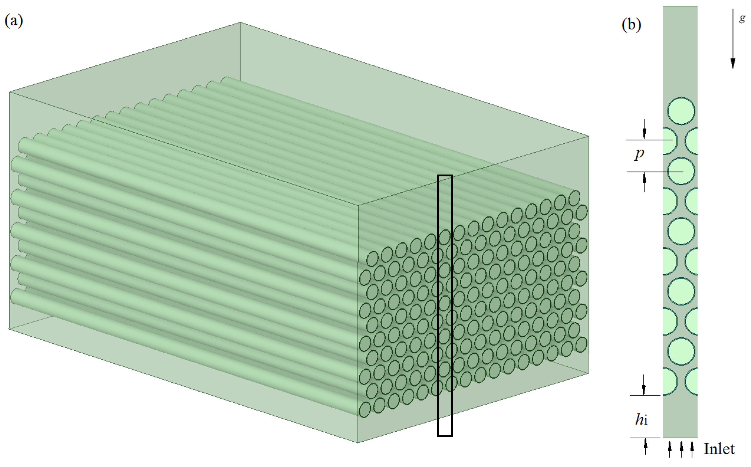
The considered TES unit is configured according to a staggered tube bundle heat exchanger, in which the PCM is filled inside the tubes, and the heat transfer fluid (HTF) flows outside from the unit bottom, as shown in Figure 1. The tube bundle consists of N groups of staggered tubes in the horizontal direction. Each group contains 10 staggered tubes, as shown in Figure 1a. Due to the periodic arrangement of tubes along the horizontal direction, the region shown in Figure 1b is selected for the numerical analysis. The 2D model was selected because it can significantly save computational time while ensuring calculation accuracy, considering that the tube length is much greater than the tube diameter. The height and width of the selected region are 500 and 40 mm, respectively. The inner and outer diameters of the tubes are 30 and 32 mm, respectively. The tube pitches in x- and y-direction (p) are 40.00 and 34.64 mm, respectively. The distance from the bottom tube to the unit bottom (hi) is 50 mm. For the purpose of enhancing heat transfer, the tube bundles oscillate along the vertical direction at a speed of v = A × sin(2w × t), where A and w are the oscillation amplitude and frequency, respectively. Paraffin wax is taken as the PCM since it is cheap and has excellent performance, such as noncorrosive, odourless, long-lasting, etc. [44]. Water is the HTF. The tubes are made of copper. Detailed thermophysical properties of the materials are summarized in Table 1.
2.2. Governing Equation
The enthalpy-porosity model was used in the present study to handle the phase transition in the TES unit. The following assumptions are considered in the development of the mathematical model: (1) The density of paraffin wax is constant at solid and liquid state except when the Boussinesq approximation was used to handle the natural convection in liquid region, (2) The liquid paraffin is incompressible and its flow is laminar and unsteady, (3) The thermophysical properties of paraffin, water and copper are invariable with temperature considering that the temperature variation range is not large. The governing equations can then be described as follows:
Continuity equation:
Momentum equation:
Energy equation:
For HTF zones, Su and Sh equal 0. For PCM zones and . For metal zones, u, Su and Sh are equal to 0. Su is used for damping the velocity in the mushy zone, in which Amush is the mushy zone constant (104–107 kg/m3·s) and δ is a small constant (0.001) to prevent division by zero. Amush = 105 kg/m3·s is set in the present work. is buoyancy force, in which β is the thermal expansion coefficient, and g is the gravity force. f is the local liquid fraction and expressed as:
2.3. Initial and Boundary Conditions
The initial conditions for all zones are:
Melting process:
At (x, y, t = 0 s); u = v = 0, T = 298 K
Solidification process:
At (x, y, t = 0 s); u = v = 0, T = 353 K
The conditions at the water inlet are:
Melting process:
u = 0, v = 0.001 m/s, Tf = 353 K
Solidification process:
u = 0, v = 0.001 m/s, Tf = 298 K
The conditions at the water outlet are:
The conditions at the left and right symmetric boundaries are:
The conditions at the tube walls in contact with the heating water and PCM are:
2.4. Dynamic Mesh and Mesh Generation
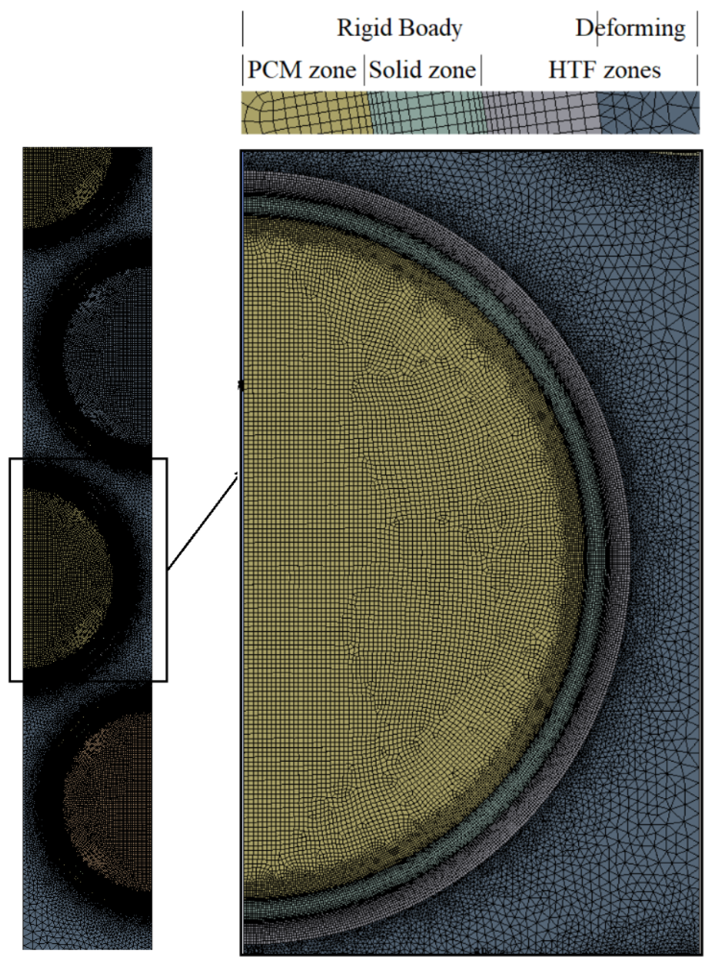
The oscillation of tube bundles was handled using the dynamic mesh technique. The spring-based smoothing method coupled with the re-meshing algorithm was adopted for the dynamic meshing. The geometrical model was then meshed using the ANSYS Meshing, which includes quadrilateral elements in the solid and PCM zones, as well as hybrid elements in the HTF zone. In the HTF zone, a concentric annulus region around the solid zone is established, and the quadrilateral elements are employed in this region, while the triangular elements are employed in the rest region, as shown in Figure 2. The annulus region was built with finer grids to capture the steep temperature gradient in the boundary layer and set it as the rigid body in the dynamic mesh set. The rest of the region of the HTF zone and its boundaries are set as the deforming type. The inlet and outlet boundaries are static zones. The rest zones and boundaries are the rigid body. The motion of the rigid body is programmed using user-defined functions (UDFs) in ANSYS Fluent for compilation, which sets the speed v = A × sin(2w × t) to every tube at the same time.
3. Numerical Considerations
3.1. Numerical Method
The computational fluid dynamics (CFD) software ANSYS FLUENT 2021R1 was employed to conduct the numerical simulation. The SIMPLE algorithm was used for the coupling of pressure and velocity [45]. The PRESTO! scheme was implemented for pressure correction. The second-order upwind scheme was used for discretising the momentum and energy equations. Under-relaxation factors for the energy equation, momentum equation and pressure correction were set as 1, 0.7 and 0.3, respectively. Residual convergences for continuity, momentum and energy were set to be 10−5, 10−5 and 10−6, respectively.
3.2. Independence Analysis
Grid independence of the numerical solution was checked by comparing the evolution of PCM liquid fraction for the case without oscillation at four grid numbers of 15,251, 42,684, 279,751 and 339,211, as shown in Figure 3a. It can be seen that the liquid fraction curves with the third and fourth mesh systems are essentially overlapped. Therefore, the mesh system with a grid number of 279,751 was employed in the following analysis. Three time steps of 0.01, 0.02, and 0.05 s were examined for the same case, as shown in Figure 3b. It can be seen that the two liquid fraction curves of the time step of 0.01 and 0.02 s are identical. Thus, the time step of 0.02 s was selected.
3.3. Model Validation
The present numerical model was validated by the numerical results reported by Darzi et al. [46]. It is noted that these numerical results were validated by experimental data reported by Dhaidan et al. [47] by comparing the shape of melting fronts. In their study, N-eicosane was filled in an annular container with an inner diameter of 40 mm and an outer diameter of 80 mm. Four fins with a thickness of 1 mm and length of 15 mm were inserted into the PCM. The same physical model was adopted, and the simulation was then carried out using the present numerical model. The comparison of the evolution of liquid fractions calculated by the present model with their results is shown in Figure 4. It is seen that the maximum difference between the two liquid fraction curves is 1.1%, which validates the numerical model. The possible reason for the difference is that different mesh systems were used in the simulations, although both were demonstrated to be mesh-independent.
4. Results and Discussion
4.1. Effect of Oscillation Time
To examine the effect of oscillation time, the cases with no oscillation and oscillation starting at 200, 400, and 800 s were simulated, and the corresponding liquid fraction contours are shown in Figure 5. The oscillation frequency and amplitude are 1.0 Hz and 1.0 mm, respectively. For the case without oscillating, the solid-liquid interface moves nearly uniformly from the walls of the tube to the centres of the tubes before t = 400 s, indicating heat conduction is dominant at this stage. The PCM in the tubes near the bottom melts faster than that near the top since the HTF enters from the bottom. As the melting progresses, more liquid PCM is present in the tubes, and the natural convection starts to develop. As shown, natural convection brings the heat upward from the tube bottom, and a few high-temperature regions are formed in tubes near the bottom at t = 800 s, indicating that heat convection becomes important in the following melting process. For the case with oscillation starting at 200 s, it is seen that the high-temperature regions near the tube bottom are much larger than those of the case without oscillation at t = 800 and 1200 s, meaning the heat convection is intensified with the presence of oscillation. As a result, the PCM melts completely in more tubes with oscillation than without at t = 1600 s. With the starting of oscillation delays from 200 to 400 s, the high-temperature regions near the tube’s bottom become smaller since the convection heat transfer is later enhanced by oscillation. With the further delay of oscillation, the high-temperature region becomes even smaller, and larger solid regions are present in the tubes at the same time.
To examine the effect of oscillation on the convection, Figure 6 shows the velocity distribution of HTF and PCM in the TES unit without oscillation and with oscillation starting at t = 200 s. For the case without oscillation, the flow of HTF reaches a steady state at t = 200 s, as can be seen, and the velocity does not change afterwards. The maximum velocity equals 6.97 × 10⁻³ m/s and is located at the thinnest part between two neighbouring tubes. In contrast, the HTF velocity changes during the PCM melting process for cases with oscillation. For example, the highest velocities are equal to 1.00 × 10⁻², 8.99 × 10⁻³ and 4.69 × 10⁻³ m/s at t = 400, 800 and 1200 s, respectively. This can be explained as follows. When the tubes are moving downward under the effect of oscillation, the liquid PCM in contact with the tubes has to move downward due to the non-slip boundary condition. Meanwhile, according to mass balance, the mass flow rate at each horizontal cross-section has to be the same and equal to the mass flow rate at the inlet. As a result, the upward flow near the centres between two neighbouring tubes has to be intensified to compensate for the downward flow near the tube surface, and then the highest velocity is significantly increased. Li et al. [48] reported that the fluctuating HTF velocity brings better heat transfer performance than the steady HTF velocity. Additionally, the flow direction of melted PCM varies with oscillation during the melting process. Taking a case with oscillation at 200 s as an example, the melted PCM flows downward at t = 800 s and upward flow at t = 1200 s due to the movement of tubes. This indicates that the tube bundle oscillation can change the convective heat transfer dominant region. Furthermore, the velocity of PCM with oscillation is larger than that without oscillation. For example, the value is 3.45 × 10⁻² m/s at t = 400 s for the case with oscillation starting at 200 s, while it is 3.45 × 10⁻³ m/s for the case without oscillation. This is because the oscillation can accelerate the motion of liquid PCM, which can further enhance convective heat transfer and lead to quicker melting of PCM in tubes for the cases with oscillation.
Figure 7 compares the instantaneous PCM liquid fraction of cases with and without oscillation as a function of time. The liquid fraction of the case with oscillation starting at t = 200 s is just slightly higher than other cases at t = 400 s as the oscillation does not enhance heat convection much when only very little liquid PCM is formed. As melting progresses, the liquid fraction becomes obviously higher with the starting of oscillation. The earlier the oscillation starts, the higher the liquid fraction. Compared to the case without oscillating (1964 s), the complete melting time is reduced by 8.3, 8.1 and 5.2% for cases with oscillation starting at 200 (1800 s), 400 (1805 s) and 800 s (1862 s), respectively. The complete melting time of the cases with oscillation starting at 200 and 400 s are nearly the same, suggesting that a too-early oscillation of the tubes is not necessary since the liquid region is too small at the initial stage to form convection, and thus, the convective heat transfer can hardly be enhanced.
4.2. Effect of Oscillation Frequency
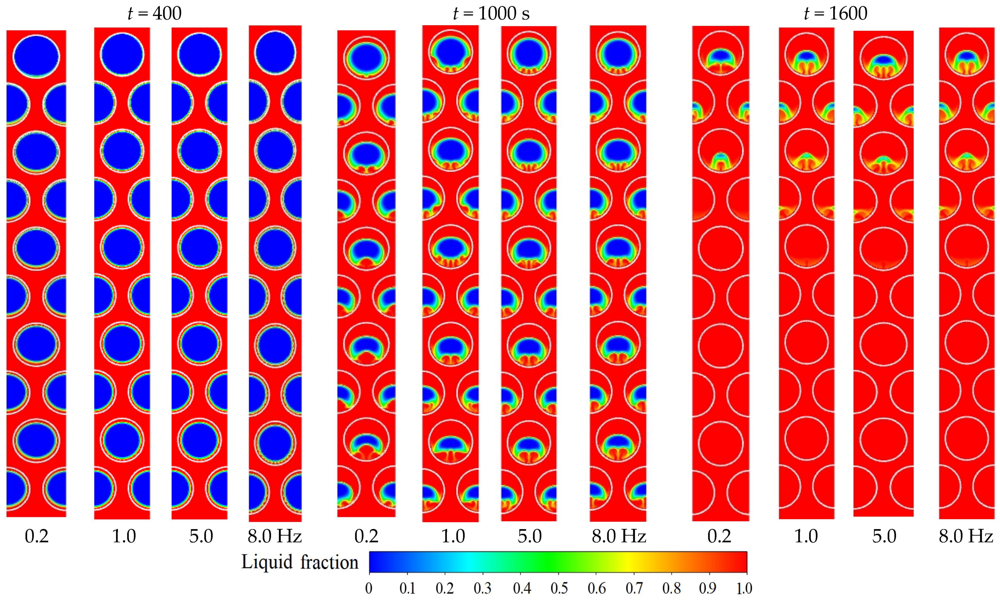
Figure 8 shows the distribution of PCM liquid fraction at the oscillation frequencies of 0.2, 1.0, 5.0 and 8.0 Hz and an oscillation amplitude of 1.0 mm. The oscillation starts at 200 s for all cases. It can be seen in Figure 8 that a higher oscillation frequency tends to make the solid-liquid interface more uneven at t = 400 s. Those uneven solid-liquid interfaces actually start convection, and this suggests that a higher oscillation frequency can facilitate the formation of convection. This phenomenon can further be seen in the liquid fraction contours at t = 1000 s. More high-temperature regions can be observed near the tube’s bottom at the frequency of 8.0 Hz than that at 0.2 Hz. At t = 1600 s, it is seen that the case with an oscillation frequency of 0.2 Hz has more solid PCM present in the top tube, while it has more tubes with completely melted PCM. This result shows that a higher oscillation frequency does not lead to faster melting of PCM, but it makes the melting process more uniform.
The evolution of liquid fraction for cases with different oscillation frequencies is further shown in Figure 9. As seen, the liquid fraction curves with these four different oscillation frequencies are nearly identical, suggesting the oscillation frequency has little effect on the total melting amount of PCM. The high oscillation frequency (8.0 Hz) leads to a slightly higher liquid fraction at the former melting stage, as a high oscillation can better enhance heat convection with a small amount of liquid PCM. However, the low oscillation frequency (0.2 Hz) results in a slightly higher liquid fraction at the later melting stage and the main reason might be that a high oscillation frequency can suppress the convection as the liquid PCM is forced to move to the opposite direction too frequently. Finally, the PCM melts completely at nearly the same time with different oscillation frequencies, and the complete melting time of PCM with oscillation frequencies of 0.2, 1.0, 5.0 and 8.0 Hz are 1797, 1800, 1801 and 1803 s, respectively, indicating that the oscillation frequency has a negligible effect on the PCM liquid fraction evolution among the considered cases. This can be explained as follows: the acceleration of liquid PCM to a certain speed at a direction, i.e., the formation of convection, requires time, and a too-high frequency shifts the motion direction of tubes too quickly and thus prevents the formation of high-speed liquid PCM. Thus, a higher frequency does not further enhance the melting.
4.3. Effect of Oscillation Amplitude
Figure 10 shows the liquid fraction contours for PCM with oscillation amplitudes of 0.5, 1.0, and 1.5 mm and an oscillation frequency of 0.2 Hz. Again, the oscillation starts at 200 s for all cases. As shown, the solid PCM regions become slightly smaller with the increase of oscillation amplitude, indicating that the melting process is better enhanced with a higher oscillation amplitude. This can be clearly observed by comparing the liquid fraction contours at t = 1600 s, in which less solid is present for the case with higher oscillation amplitude. The evolution of liquid fraction for cases with different oscillation amplitude is further shown in Figure 11. During the whole melting process, the liquid fraction is always higher with a higher oscillation amplitude, especially at the later melting stage when a large amount of liquid PCM is present to enhance the effect of oscillation. The complete melting time of PCM with oscillation amplitudes of 0.5, 1.0, and 1.5 mm is 1832, 1800, and 1746 s, respectively, which further proves that the oscillation amplitude has an important effect on the melting enhancement. This is because the tubes have to move at a higher speed at a higher oscillation amplitude, and then the convection is greatly enhanced and melting time shortened.
4.4. Solidification Process
To examine the effect of oscillation on the PCM solidification process, the cases with oscillation starting at different times during solidification were simulated. The initial temperature of PCM is 353 K, and the inlet water temperature is 295 K. Other boundary conditions are kept the same as the melting process. Figure 12 shows the liquid fraction contours of PCM at different instants during solidification without oscillation and with oscillation starting at 100, 200, and 300 s at A = 1.0 mm and w = 1.0 Hz. As shown, PCM solidifies faster at the lower portion of each tube than at the upper portion since the HTF enters from the bottom. The PCM solidifies faster for the case with oscillation than without, as can be clearly seen by comparing the liquid fraction contours at t = 1200 s. The cases with oscillation show very few differences in liquid fraction contours during the solidification process, indicating that the effect of oscillation on the solidification process is not significant. To further check the differences in solidification between these cases, the evolution of liquid fraction is shown in Figure 13. As seen, the liquid fraction curves are obviously lower with oscillation than without during the later solidification process at t > 400 s, suggesting that the oscillation mainly enhances the solidification at the later stage. The complete solidification time for the case without oscillation is 1444 s, and those with oscillation starting at 100, 200 and 300 s are 1338, 1345 and 1355 s, respectively. With oscillation, the solidification time is obviously reduced compared to the case without oscillation. However, the solidification times difference for the cases with oscillation is negligible, although the results show that an early oscillation can lead to a shorter solidification time. The reason is mainly because the effect of oscillation becomes significant only at the later solidification process at t > 400 s.
5. Conclusions
A TES unit with PCM filled-in tube bundles and HTF flows outside was studied. The oscillation of the tube bundle was applied to enhance the phase transition process. The main conclusions are as follows.
- (1)
- The oscillation of the tube bundle can shorten the melting time of the TES system since the convection in liquid PCM is enhanced through the movement of tubes. The case with a frequency of 1 Hz and amplitude of 1 mm oscillation starting at t = 200 s has an 8.3% shorter melting time compared to the case without oscillation.
- (2)
- A too early oscillation is not necessary for the melting enhancement as too little liquid PCM is present at the early melting stage and thus convection is negligible. The cases with the oscillation starting at 200 and 400 s show nearly the same melting time, which are 1800 and 1805 s, respectively.
- (3)
- The effect of oscillation frequency on the PCM melting is not significant among all considered cases. A high oscillation frequency can slightly enhance convection at the former melting stage and slightly suppress convection at the later melting stage. The cases with oscillation frequencies of 0.2, 1.0, 5.0 and 8.0 Hz show nearly the same melting times, which are 1797, 1800, 1801 and 1803 s, respectively.
- (4)
- The effect of oscillation amplitude on the PCM melting is important, and a higher oscillation amplitude can further shorten the melting time compared to a lower oscillation amplitude. Due to a large amount of liquid PCM, the increase of oscillation amplitude leads to the significant enhancement of convection. The melting time of cases with oscillation amplitudes of 0.5, 1.0, and 1.5 mm are 1832, 1800 and 1746 s, respectively.
- (5)
- The solidification process can also be accelerated by the oscillation of tubes, and the solidification times of the cases without oscillation, with oscillation starting at 100, 200 and 300 s, are 1444, 1338, 1345 and 1355 s, respectively. The effect of oscillation on solidification becomes significant at the later solidification stage as the liquid fraction curves show clear discrepancies at t > 400 s.
- (6)
- The best phase transition performance can be obtained with the oscillation starting at an early time and a higher oscillation amplitude. The case with oscillation starting at 200 s and an amplitude of 1.5 mm gives the shortest melting time among all cases, which is 1746 s.
This present study shows the oscillation of a tube bundle can enhance the melting and solidification of the bundled-tube TES system at the same time. It should be noted that this study only examines the effect of oscillation of tubes at the vertical direction under a specific heat transfer condition, and the effects of oscillation directions under various inlet temperatures, different arrangements of multiple PCMs, and working fluid can be further explored.
Author Contributions
Software, Y.X.; Investigation, D.C.; Data curation, C.Y.; Writing—original draft, J.L.; Writing—review and editing, C.N. All authors have read and agreed to the published version of the manuscript.
Funding
This research was funded by Science and Technology Project of Hebei Education Department (No. BJK2024041), National Natural Science Foundation of China (Grant No. 51804348) and Water Resources Science and Technology Program of Hunan Province (SKJ023059-30).
Data Availability Statement
Data are contained within the article.
Acknowledgments
We are grateful to the High-Performance Computing Center of Central South University for assistance with the computations.
Conflicts of Interest
The authors declare no conflict of interest.
References
- Liu, Z.; Liu, B.; Ding, X.; Wang, F. Research on optimization of energy storage regulation model considering wind–solar and multi-energy complementary intermittent energy interconnection. Energy Rep. 2022, 8, 490–501. [Google Scholar] [CrossRef]
- Mostafavi Tehrani, S.S.; Shoraka, Y.; Nithyanandam, K.; Taylor, R.A. Shell-and-tube or packed bed thermal energy storage systems integrated with a concentrated solar power: A techno-economic comparison of sensible and latent heat systems. Appl. Energy 2019, 238, 887–910. [Google Scholar] [CrossRef]
- Romaní, J.; Gasia, J.; Solé, A.; Takasu, H.; Kato, Y.; Cabeza, L.F. Evaluation of energy density as performance indicator for thermal energy storage at material and system levels. Appl. Energy 2019, 235, 954–962. [Google Scholar] [CrossRef]
- Aftab, W.; Usman, A.; Shi, J.; Yuan, K.; Qin, M.; Zou, R. Phase change material-integrated latent heat storage systems for sustainable energy solutions. Energy Environ. Sci. 2021, 14, 4268–4291. [Google Scholar] [CrossRef]
- Gasia, J.; Maldonado, J.M.; Galati, F.; De Simone, M.; Cabeza, L.F. Experimental evaluation of the use of fins and metal wool as heat transfer enhancement techniques in a latent heat thermal energy storage system. Energy Convers. Manag. 2019, 184, 530–538. [Google Scholar] [CrossRef]
- Rudra Murthy, B.V.; Nidhul, K.; Gumtapure, V. Performance evaluation of novel tapered shell and tube cascaded latent heat thermal energy storage. Sol. Energy 2021, 214, 377–392. [Google Scholar] [CrossRef]
- Kumar, A.; Saha, S.K. Performance study of a novel funnel shaped shell and tube latent heat thermal energy storage system. Renew. Energy 2021, 165, 731–747. [Google Scholar] [CrossRef]
- Sodhi, G.S.; Muthukumar, P. Compound charging and discharging enhancement in multi-PCM system using non-uniform fin distribution. Renew. Energy 2021, 171, 299–314. [Google Scholar] [CrossRef]
- Zhu, Y.; Wang, D.; Li, P.; Yuan, Y.; Tan, H. Optimization of exergy efficiency of a cascaded packed bed containing variable diameter particles. Appl. Therm. Eng. 2021, 188, 116680. [Google Scholar] [CrossRef]
- Patil, J.R.; Mahanwar, P.A.; Sundaramoorthy, E.; Mundhe, G.S. A review of the thermal storage of phase change material, morphology, synthesis methods, characterization, and applications of microencapsulated phase change material. J. Polym. Eng. 2023, 43, 354–375. [Google Scholar] [CrossRef]
- Mohamed Moussa, E.I.; Karkri, M. A numerical investigation of the effects of metal foam characteristics and heating/cooling conditions on the phase change kinetic of phase change materials embedded in metal foam. J. Energy Storage 2019, 26, 100985. [Google Scholar] [CrossRef]
- Sadeghi, H.M.; Babayan, M.; Chamkha, A. Investigation of using multi-layer PCMs in the tubular heat exchanger with periodic heat transfer boundary condition. Int. J. Heat Mass Transf. 2020, 147, 118970. [Google Scholar] [CrossRef]
- Siahpush, A.; O’Brien, J.; Crepeau, J. Phase change heat transfer enhancement using copper porous foam. J. Heat Transf. 2008, 130, 082301. [Google Scholar] [CrossRef]
- Safari, V.; Abolghasemi, H.; Kamkari, B. Experimental and numerical investigations of thermal performance enhancement in a latent heat storage heat exchanger using bifurcated and straight fins. Renew. Energy 2021, 174, 102–121. [Google Scholar] [CrossRef]
- Deng, S.; Nie, C.; Wei, G.; Ye, W.-B. Improving the melting performance of a horizontal shell-tube latent-heat thermal energy storage unit using local enhanced finned tube. Energy Build. 2019, 183, 161–173. [Google Scholar] [CrossRef]
- Ye, W.; Jamshideasli, D.; Khodadadi, J.M. Improved Performance of Latent Heat Energy Storage Systems in Response to Utilization of High Thermal Conductivity Fins. Energies 2023, 16, 1277. [Google Scholar] [CrossRef]
- Manoj Kumar, P.; Sudarvizhi, D.; Stalin, P.M.J.; Aarif, A.; Abhinandhana, R.; Renuprasanth, A.; Sathya, V.; Ezhilan, N.T. Thermal characteristics analysis of a phase change material under the influence of nanoparticles. Mater. Today Proc. 2021, 45, 7876–7880. [Google Scholar] [CrossRef]
- Nie, C.; Liu, J.; Deng, S. Effect of geometric parameter and nanoparticles on PCM melting in a vertical shell-tube system. Appl. Therm. Eng. 2021, 184, 116290. [Google Scholar] [CrossRef]
- Amidu, M.A.; Ali, M.; Alkaabi, A.K.; Addad, Y. A critical assessment of nanoparticles enhanced phase change materials (NePCMs) for latent heat energy storage applications. Sci. Rep. 2023, 13, 7829. [Google Scholar] [CrossRef]
- Huang, S.; Lu, J.; Li, Y. Numerical study on the influence of inclination angle on the melting behaviour of metal foam-PCM latent heat storage units. Energy 2022, 239, 122489. [Google Scholar] [CrossRef]
- Nie, C.; Liu, J.; Deng, S. Effect of geometry modification on the thermal response of composite metal foam/phase change material for thermal energy storage. Int. J. Heat Mass Transf. 2021, 165, 120652. [Google Scholar] [CrossRef]
- Andreozzi, A.; Asinari, P.; Barletta, A.; Bianco, V.; Bocanegra, J.A.; Brandão, P.V.; Buonomo, B.; Cappabianca, R.; Celli, M.; Chiavazzo, E.; et al. Heat Transfer and Thermal Energy Storage Enhancement by Foams and Nanoparticles. Energies 2023, 16, 7421. [Google Scholar] [CrossRef]
- Mahdavi, M.; Tiari, S.; Pawar, V. A numerical study on the combined effect of dispersed nanoparticles and embedded heat pipes on melting and solidification of a shell and tube latent heat thermal energy storage system. J. Energy Storage 2020, 27, 101086. [Google Scholar] [CrossRef]
- Khalilmoghadam, P.; Rajabi-Ghahnavieh, A.; Shafii, M.B. A novel energy storage system for latent heat recovery in solar still using phase change material and pulsating heat pipe. Renew. Energy 2021, 163, 2115–2127. [Google Scholar] [CrossRef]
- Nakhchi, M.E.; Hatami, M.; Rahmati, M. A numerical study on the effects of nanoparticles and stair fins on performance improvement of phase change thermal energy storages. Energy 2021, 215, 119112. [Google Scholar] [CrossRef]
- Yang, X.; Wei, P.; Liu, G.; Bai, Q.; He, Y.L. Performance evaluation on the gradient design of pore parameters for metal foam and pin fin-metal foam hybrid structure. Appl. Therm. Eng. 2020, 175, 115416. [Google Scholar] [CrossRef]
- Selvakumar, R.D.; Wu, J.; Alkaabi, A.K. Electrohydrodynamic acceleration of charging process in a latent heat thermal energy storage module. Appl. Therm. Eng. 2024, 242, 122475. [Google Scholar] [CrossRef]
- Yang, C.; Zheng, Z.-J.; Cai, X.; Xu, Y. Experimental study on the effect of rotation on melting performance of shell-and-tube latent heat thermal energy storage unit. Appl. Therm. Eng. 2022, 215, 118877. [Google Scholar] [CrossRef]
- Kurnia, J.C.; Sasmito, A.P. Numerical investigation of heat transfer performance of a rotating latent heat thermal energy storage. Appl. Energy 2018, 227, 542–554. [Google Scholar] [CrossRef]
- Soltani, H.; Soltani, M.; Karimi, H.; Nathwani, J. Optimization of shell and tube thermal energy storage unit based on the effects of adding fins, nanoparticles and rotational mechanism. J. Clean. Prod. 2022, 331, 129922. [Google Scholar] [CrossRef]
- Qu, X.; Jiang, S.; Qi, X. Experimental investigation on performance improvement of latent heat storage capsule by oscillating movement. Appl. Energy 2022, 316, 119130. [Google Scholar] [CrossRef]
- Zheng, Z.J.; Sun, Y.; Chen, Y.; He, C.; Yin, H.; Xu, Y. Study of the melting performance of shell-and-tube latent heat thermal energy storage unit under the action of rotating finned tube. J. Energy Storage 2023, 62, 106801. [Google Scholar] [CrossRef]
- Huang, X.; Li, F.; Guo, J.; Li, Y.; Du, R.; Yang, X.; He, Y.L. Design optimization on solidification performance of a rotating latent heat thermal energy storage system subject to fluctuating heat source. Appl. Energy 2024, 362, 122997. [Google Scholar] [CrossRef]
- Li, N.; Zhao, Y.; Wang, H.; Chen, Q.; Li, Z.; Ma, Y.; Tang, G. Thermal and hydraulic performance of a compact precooler with mini-tube bundles for aero-engine. Appl. Therm. Eng. 2022, 200, 117656. [Google Scholar] [CrossRef]
- Chen, K.; Guo, L.; Xie, X.; Liu, W. Experimental investigation on enhanced thermal performance of staggered tube bundles wrapped with metallic foam. Int. J. Heat Mass Transf. 2018, 122, 459–468. [Google Scholar] [CrossRef]
- Dubovsky, V.; Ziskind, G.; Letan, R. Analytical model of a PCM-air heat exchanger. Appl. Therm. Eng. 2011, 31, 3453–3462. [Google Scholar] [CrossRef]
- Ezra, M.; Kozak, Y.; Dubovsky, V.; Ziskind, G. Analysis and optimization of melting temperature span for a multiple-PCM latent heat thermal energy storage unit. Appl. Therm. Eng. 2016, 93, 315–329. [Google Scholar] [CrossRef]
- Promoppatum, P.; Yao, S.C.; Hultz, T.; Agee, D. Experimental and numerical investigation of the cross-flow PCM heat exchanger for the energy saving of building HVAC. Energy Build. 2017, 138, 468–478. [Google Scholar] [CrossRef]
- Liu, J.; Xu, C.; Ju, X.; Yang, B.; Ren, Y.; Du, X. Numerical investigation on the heat transfer enhancement of a latent heat thermal energy storage system with bundled tube structures. Appl. Therm. Eng. 2017, 112, 820–831. [Google Scholar] [CrossRef]
- Alhusseny, A.; Al-Zurfi, N.; Nasser, A.; Al-Fatlawi, A.; Aljanabi, M. Impact of using a PCM-metal foam composite on charging/discharging process of bundled-tube LHTES units. Int. J. Heat Mass Transf. 2020, 150, 119320. [Google Scholar] [CrossRef]
- Tang, S.Z.; He, Y.; He, Y.L.; Wang, F.L. Enhancing the thermal response of a latent heat storage system for suppressing temperature fluctuation of dusty flue gas. Appl. Energy 2020, 266, 114870. [Google Scholar] [CrossRef]
- Kang, Z.; Zhou, W.; Qiu, K.; Wang, C.; Qin, Z.; Zhang, B.; Yao, Q. Numerical Simulation of an Indirect Contact Mobilized Thermal Energy Storage Container with Different Tube Bundle Layout and Fin Structure. Sustainability 2023, 15, 5511. [Google Scholar] [CrossRef]
- Pignata, A.; Minuto, F.D.; Lanzini, A.; Papurello, D. A feasibility study of a tube bundle exchanger with phase change materials: A case study. J. Build. Eng. 2023, 78, 107622. [Google Scholar] [CrossRef]
- Sidik, N.A.C.; Kean, T.H.; Chow, H.K.; Rajaandra, A.; Rahman, S.; Kaur, J. Performance enhancement of cold thermal energy storage system using nanofluid phase change materials: A review. Int. Commun. Heat Mass Transf. 2018, 94, 85–95. [Google Scholar] [CrossRef]
- Deng, S.; Nie, C.; Jiang, H.; Ye, W.B. Evaluation and optimization of thermal performance for a finned double tube latent heat thermal energy storage. Int. J. Heat Mass Transf. 2019, 130, 532–544. [Google Scholar] [CrossRef]
- Rabienataj Darzi, A.A.; Jourabian, M.; Farhadi, M. Melting and solidification of PCM enhanced by radial conductive fins and nanoparticles in cylindrical annulus. Energy Convers. Manag. 2016, 118, 253–263. [Google Scholar] [CrossRef]
- Dhaidan, N.S.; Khodadadi, J.M.; Al-Hattab, T.A.; Al-Mashat, S.M. Experimental and numerical investigation of melting of NePCM inside an annular container under a constant heat flux including the effect of eccentricity. Int. J. Heat Mass Transf. 2013, 67, 455–468. [Google Scholar] [CrossRef]
- Li, Z.; Yu, X.; Wang, L.; Lu, Y.; Huang, R.; Chang, J.; Jiang, R. Effects of fluctuating thermal sources on a shell-and-tube latent thermal energy storage during charging process. Energy 2020, 199, 117400. [Google Scholar] [CrossRef]
Figure 1.
Schematic description of the TES units considered in the present study: (a) physical model; (b) selected computational domain.
Figure 1.
Schematic description of the TES units considered in the present study: (a) physical model; (b) selected computational domain.

Figure 2.
The selected portion of the computational domain and the corresponding mesh system.

Figure 3.
Effects of grid size and time step on the transient variation of liquid fraction at (a) different grid numbers and (b) time steps.
Figure 3.
Effects of grid size and time step on the transient variation of liquid fraction at (a) different grid numbers and (b) time steps.

Figure 4.
Comparison of the results of the present model with reported data [46].
Figure 4.
Comparison of the results of the present model with reported data [46].

Figure 5.
The liquid fraction contour of PCM with oscillation starts at different times.

Figure 6.
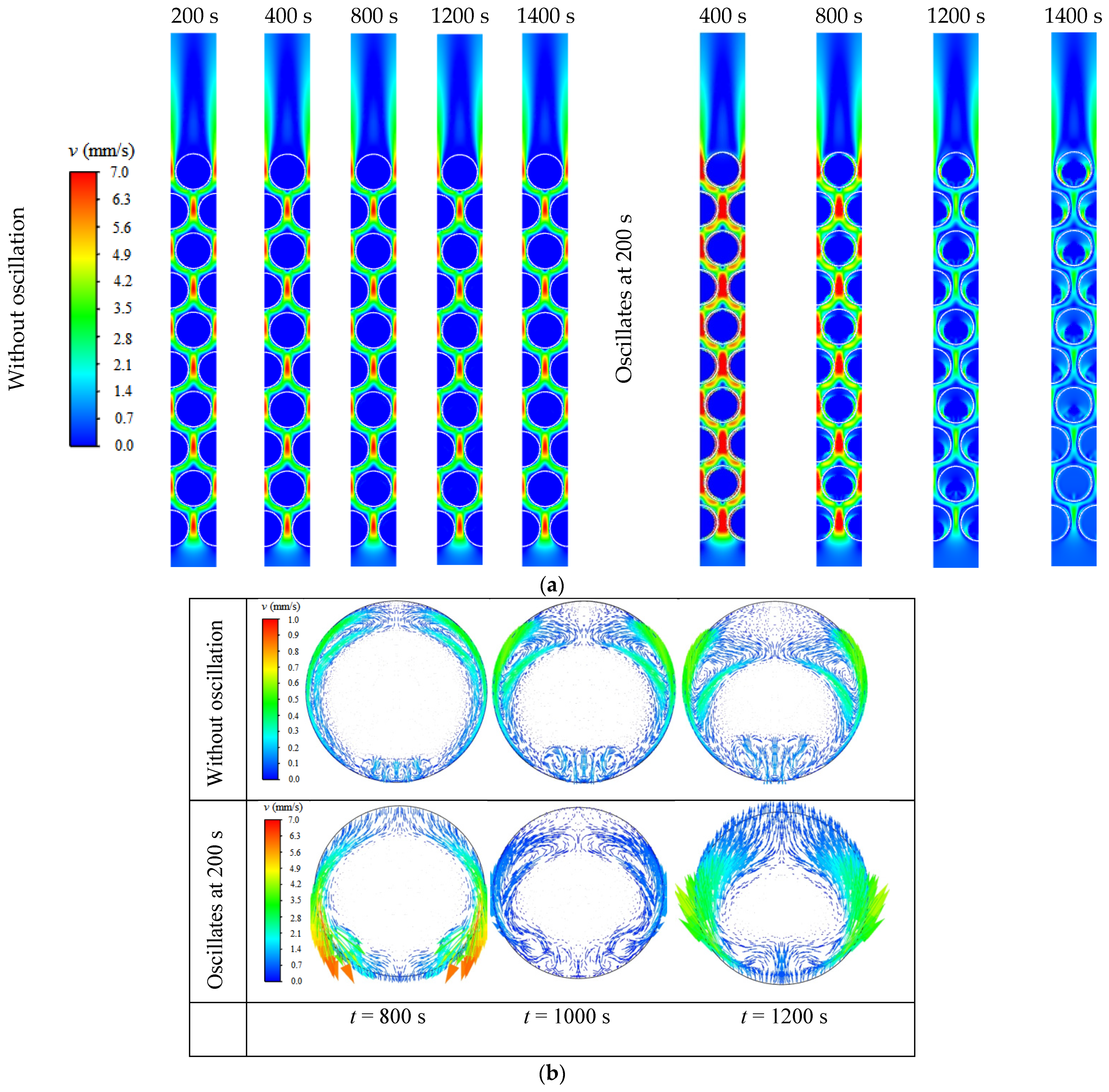
Velocity distribution of cases without oscillation and with oscillates at t = 200 s: (a) Velocity contours of HTF and PCM at different times. (b) Velocity vectors of liquid PCM in the tube at row six at t = 800, 1000 and 1200 s.
Figure 6.
Velocity distribution of cases without oscillation and with oscillates at t = 200 s: (a) Velocity contours of HTF and PCM at different times. (b) Velocity vectors of liquid PCM in the tube at row six at t = 800, 1000 and 1200 s.

Figure 7.
The evolution of PCM liquid fraction of cases with and without oscillations.

Figure 8.
Liquid fraction contours for PCM at different oscillation frequencies.

Figure 9.
The evolution of PCM liquid fraction at different oscillation frequencies.

Figure 10.
Liquid fraction contours of PCM at different oscillation amplitudes.

Figure 11.
The evolution of PCM liquid fraction at different oscillation amplitudes.

Figure 12.
Liquid fraction contours for PCM with oscillation starting at different times during solidification.
Figure 12.
Liquid fraction contours for PCM with oscillation starting at different times during solidification.

Figure 13.
The evolution of PCM liquid fraction with oscillation starting at different times during solidification.
Figure 13.
The evolution of PCM liquid fraction with oscillation starting at different times during solidification.


Table 1.
The thermophysical properties of the paraffin, water and copper.
| k (W/m·K) | ρ (kg/m3) | cp (J/kg·K) | Ts (K) | Tl (K) | L (J/kg) | μ (Pa·s) | β (K−1) | |
|---|---|---|---|---|---|---|---|---|
| Paraffin | 0.2 | 850/760 | 2000 | 302.15 | 309.15 | 165,000 | 0.0254 | 0.00005 |
| Water | 0.6 | 998.2 | 4182 | - | - | - | 0.001 | - |
| Copper | 387.6 | 8978 | 381 | - | - | - | - | - |
Disclaimer/Publisher’s Note: The statements, opinions and data contained in all publications are solely those of the individual author(s) and contributor(s) and not of MDPI and/or the editor(s). MDPI and/or the editor(s) disclaim responsibility for any injury to people or property resulting from any ideas, methods, instructions or products referred to in the content. |
© 2024 by the authors. Licensee MDPI, Basel, Switzerland. This article is an open access article distributed under the terms and conditions of the Creative Commons Attribution (CC BY) license (https://creativecommons.org/licenses/by/4.0/).
Share and Cite
MDPI and ACS Style
Liu, J.; Xiao, Y.; Chen, D.; Ye, C.; Nie, C. Melting and Solidification Characteristics of PCM in Oscillated Bundled-Tube Thermal Energy Storage System. Energies 2024, 17, 1973. https://doi.org/10.3390/en17081973
AMA Style
Liu J, Xiao Y, Chen D, Ye C, Nie C. Melting and Solidification Characteristics of PCM in Oscillated Bundled-Tube Thermal Energy Storage System. Energies. 2024; 17(8):1973. https://doi.org/10.3390/en17081973
Chicago/Turabian StyleLiu, Jiangwei, Yuhe Xiao, Dandan Chen, Chong Ye, and Changda Nie. 2024. "Melting and Solidification Characteristics of PCM in Oscillated Bundled-Tube Thermal Energy Storage System" Energies 17, no. 8: 1973. https://doi.org/10.3390/en17081973
Note that from the first issue of 2016, this journal uses article numbers instead of page numbers. See further details here.