
Two-Stage Solar–NaOH Thermochemical Heat Pump Heating System for Building Heating: Operations Strategies and Theoretical Performance


1
College of Civil Engineering and Architecture, Zhejiang University, Hangzhou 310058, China
2
The Architectural Design and Research Institute, Zhejiang University, Hangzhou 310058, China
3
Center for Balance Architecture, Zhejiang University, Hangzhou 310058, China
*
Author to whom correspondence should be addressed.
Energies 2024, 17(8), 1976; https://doi.org/10.3390/en17081976
Submission received: 2 March 2024
/
Revised: 17 April 2024
/
Accepted: 19 April 2024
/
Published: 22 April 2024
(This article belongs to the Section A2: Solar Energy and Photovoltaic Systems)
Abstract
:Heating buildings with solar energy is challenged by the seasonal mismatch between solar availability and heating demand. Thermochemical energy storage is a promising technology to overcome this challenge because of its high energy density. In building applications, space requirement is also an important consideration. Therefore, both the storage space and collector areas are important considerations, with only the latter often being neglected in previous studies. This paper proposes a novel two-stage thermochemical heat pump heating system based on the working pair of NaOH/H2O. We demonstrate that this system can work with a concentration difference (70% wt–30% wt) for the climate in hot summer and cold winter regions in China. The energy storage density based on the discharged solution is 363 kWh/m3. With this solar-driven thermochemical heat pump heating system, 35.13 m2 of collectors and 10.48 tons of 70% wt NaOH solution are sufficient to complete a full charge–discharge cycle and meet the heating demand of a single-family house (winter space heating + DHW: 9370 kWh, summer DHW: 2280 kWh). The theoretical maximum storage for solution (discharged + water tank) is 32.47 m3. Compared with the sensible seasonal storage alternative, the collector area is reduced by 12.5% and the storage space is reduced by 59%, with a possible further reduction through optimization. With the potential to be further optimized for space saving, the two-stage solar–NaOH heat pump heating system is an energy-efficient and space-efficient heating system for buildings in the hot summer and cold winter regions of China.
1. Introduction
The operations of buildings consumed 30% of global final energy in 2022 [1]. It is projected that global energy consumption and CO2 emissions will rise by 50% and 10%, respectively, over the next two decades [2]. China has set a dual-carbon strategy that aims to achieve carbon peaking by 2030 and carbon neutrality by 2060. Although the development and utilization of traditional fossil fuels will continue in the near future, their negative impact on the global environment cannot be ignored. Consequently, the energy crisis and the need for sustainable development drive the global demand for alternative energy sources [3,4], particularly renewable energy [5,6]. Solar energy is a potentially effective renewable energy source for space heating and domestic hot water (DHW) [7,8]. However, its efficient usage requires effective energy storage.
The temporal mismatch between solar availability and heating demand has motivated the development of seasonal thermal energy storage (STES) to meet the heating demand of buildings [9]. In practice, solar thermal heating systems using short-term storage are normally designed with a small solar fraction to maximize financial gains [10]. With seasonal storage, high solar fractions of up to 100% can be achieved. On a large scale, STES based on sensible heat storage has proved successful both technologically and economically in the use of solar energy [6,11]. However, sensible heat storage has a relatively low storage density and requires a large space. In addition, it suffers thermal losses, especially in long-term applications [12]. In comparison, thermochemical energy storage is known to have a higher energy density, higher exergetic efficiency, and higher operating temperatures [13,14,15], and therefore requires less space [16]. In building applications, installation spaces, including material storage space and solar collectors, are a crucial factor in feasibility analyses [17,18,19].
Thermochemical heat storage (TCHS), also called sorption heat storage [20], can be divided into adsorption-based storage and absorption-based storage, although more often sorption that is based on chemical reactions or that involves multiple sorption processes is often separated out as different groups [21]. Adsorption materials that are used as sorbent materials in energy storage include zeolite and silica gel. Absorption materials as sorbent materials can be solutions of LiBr [22], NH3 [23], and LiCl [24], or solid composite materials, such as MgSO4–zeolite [25] and MgCL2–zeolite [26]. However, the sorption of composite materials can involve both sorption processes and even chemical reactions. The energy storage density (ESD) of TCHS from theoretical calculations and laboratory measurements typically ranges from below 100 kWh/m3 to 1000 kWh/m3, with those of absorption-based storage mostly higher than those of adsorption-based storage [21].
Although the present development of TCHS technology is still at an early stage and is not yet market-ready, its potential for carbon reduction is widely recognized. Prototypes for many materials have been reported in the literature. Readers can refer to recent review articles [27,28,29]. A detailed account of the studied working pairs for absorption heat pumps in the literature can be found in Ji et al. [30]. Applications of TCHS in buildings have also been explored. Frazzica and Freni [31] discussed the potential adsorption-based working pairs that can be compatible with non-concentrated solar collections for building applications. Donkers et al. [32] reviewed 563 salt hydrates as sorbent materials and discussed screening methods for DHW applications. Li et al. [33] discussed the feasibility of using MgO/H2O as the working pair for a TCHS for district heating in northern China. Compared with conventional sensible storage, the proposed system can reduce the need for concentrated collectors by two-thirds. Gao and Wang [34] proposed a TCHS system for short-term storage that takes advantage of the low prices of off-peak utilities. The system features metal chlorides/ammonia as the working pair for severe cold climates and an air-source heat pump as the low-temperature energy source. Gao et al. [35] discussed a prototype with a double-stage design and the working pair of LiBr/H2O. Tzinnis and Baldini [36] proposed a system combining sorption storage and an air-source heat pump (ASHP) in a serial configuration for load shifting to achieve a high autarky level of heating energy. Although small-scale laboratory prototypes are discussed in some of these studies, the analyses are largely theoretical.
Among the working pairs, the NaOH/H2O pair has the advantages of a low price, high heat transfer coefficient, high energy density, short recovery time, and storage temperature compatibility with conventional solar collectors. Its potential has been long recognized. Weber and Dorer [37] described the working principle of a prototype and suggested a double-stage system for better performance. Reactors are the key components and mass transfer is the limiting process for this type of TCHS. More specifically, Fumey et al. [38] identified that water transport in the film rather than at the liquid–gas interface limits the vapor sorption rate and hence the performance of the reactors. Previous studies have shown that a spiral-finned heat and mass exchanger [39] is better than a tube bundle-type exchanger [40]. With a spiral-finned reactor, Fumey et al. [39] achieved a theoretical energy density of 435 kWh/m3 in a lab-scale module with a single-stage process from a 27% to 53% wt solution range. Storage performance is highly dependent on the operation conditions of the sorption process [41]. A higher energy density is possible with a greater range of solution concentrations. However, as pointed out by Weber and Dorer [37], two-stage processes may be required to achieve a valid vapor pressure difference.
This study aims to further explore the potential of the NaOH/H2O working pair in providing heat for space heating and domestic hot water (DHW). A novel two-stage thermochemical heat pump heating system is proposed to achieve a larger concentration difference and hence a higher energy density. The system features air-source energy for evaporators and has an integrated design with non-concentrated solar heating. We use a static model to examine the energy efficiency and spatial performance in a residential heating scenario situated in the hot summer and cold winter regions in China. The energy storage density is compared with those of single-stage systems from the literature. The spatial performance is compared with those of alternative systems that are based on conventional storage. In the following sections, the system configuration, the static model, and the studied case are presented in Section 2. The results of the case study are presented and discussed in Section 3. Section 4 discusses the limitations of the study and recommendations for future work. Section 5 presents the conclusions of the study.
2. Materials and Methods
2.1. System Configuration
A solar–NaOH-based thermochemical heat pump (solar–NaOH TCHP) heating system is proposed to meet the building heating demand. This study demonstrates the concept and feasibility in an exemplary building scenario and discusses the performance in energy and space (the required storage space and collector areas). The working principle of the TCHP is as follows. In the discharging process, the reactor acts as a heat pump, extracting heat from the low-temperature source through the evaporation of water. The solution takes in water vapor and becomes diluted, releasing the extracted heat along with its stored chemical energy for heating. In the charging process, solar heat is used to regenerate the solution by desorbing vapor out of the solution. The solution becomes concentrated again and thus regains the potential to extract the heat from the low-temperature source for heating in the next cycle.
The proposed solar–NaOH TCHP system mainly consists of a solar water heating (SWH) system, two reactors, two heat exchangers, and four tanks, as shown in Figure 1, which shows five operation modes of the system. The SWH system, represented by ‘Solar Heat’ in the figure, presumably consists of solar collectors and a water tank to provide solar heat via hot water. Each of the two NaOH reactors works as a condenser or an evaporator. Each of the heat exchangers can function as a condenser or an evaporator when heat exchange has to occur between the vapor or water and an external source, such as the air source or DHW. This configuration does not represent an optimized system for practice. Rather, it is a workable demonstration for theoretical analysis. Not all components are required in an operation process. Un-used components are grayed out in the figures for better illustration. Mass flow directions are indicated using arrows.
Figure 1a shows the following two operation modes in discharging: (1) the single-stage mode (mode 1), when a valid vapor pressure difference can be established between the evaporator at the ambient temperature and the solution at the heating (discharging) temperature; (2) the two-stage mode (mode 2), when such a valid vapor pressure difference is not possible. In the single-stage mode, heating is provided by the solar collectors or by the reactors when solar energy is not available. Only one reactor is needed and the evaporator uses an air source. The discharging temperature is 45 °C. The single-stage mode is possible at the beginning of the discharging process when both the solution concentration and the ambient temperature are high. For this purpose, an intermediate solution with a proper discharge temperature is carefully chosen to meet the following two conditions. Firstly, the discharge temperature is high enough to avoid the crystallization of the solution lye. Secondly, the reactor temperature is sufficiently high to produce DHW. In this study, the discharging temperature is 45 °C and the intermediate concentration is 48%. The system can operate when the air temperature is above 5 °C. As the solution becomes more diluted and the air temperature decreases as the winter continues, it becomes difficult to establish a valid pressure difference. A two-stage strategy is used to extract heat from the air source (evaporator).
In the two-stage mode, both reactors are used. One serves as the first-stage reactor (reactor I) and the other serves as the second-stage reactor (reactor II). In reactor I, the remaining 70% wt solution is continually used to produce the intermediate solution, which is pumped to reactor II to produce the final 30% wt solution. While the first stage can use the air-sourced evaporator, the second stage has to use an evaporator at a higher temperature, which is achieved using the discharge heat from the first stage. The discharge heat from the second stage, along with solar heat, is used for heating.
Figure 1b shows the following three charging operation modes: (3) the single-stage mode with DHW production (mode 3), (4) the two-stage mode with DHW production (mode 4), and (5) the single-stage mode with the air source (mode 5). In mode 3, only one reactor is needed and the vapor is condensed at 40 °C to produce DHW. An intermediate 50% wt solution is chosen as the product of this charging process. This mode is suitable at the beginning of the non-heating season (from mid-March to May) when the air temperature is still low and the solution is diluted. It is easy to establish a valid pressure difference between the solution in the reactor (evaporator) and the air source (condenser). However, a condensing temperature of 40 °C can replace the air source in this mode if the condensing heat is to be used to produce DHW. As the solution becomes more concentrated and the air temperature increases in the summer, it becomes difficult to establish a valid vapor pressure difference between the intermediate solution at the charging temperature and either the DHW condensing source or the air source. Then, the system operation switches to mode 4, i.e., a two-stage charging mode. In mode 4, two reactors work in series. Part of the intermediate solution is used to replace the pure water as the condensing source to build up the required vapor pressure difference for the higher-temperature reactor (reactor II). The other part is pumped to the lower-temperature reactor (reactor I as the condenser), which discharges the heat to produce DHW. The final production is a 40% wt solution. As the heating season approaches, the ambient temperature drops below 20 °C. It is possible to build a valid pressure difference between the 40% wt solution and the air-sourced condenser. So, the system operation switches to mode 5. In this mode, the charging process concentrates the solution from 40% to 70%. It is not profitable to produce DHW using condensing heat. Instead, solar heat is used to produce DHW.
2.2. Case Study
To examine the performance of this two-stage solar–NaOH TCHP system, an analysis is performed for a residential building from Liu et al. [42]. It is a single-family house with a floor area of 220 m2 in Hangzhou, China. The annual loads of DHW and space heating are considered. A scaled-up analysis is also possible. The region of interest is part of the hot summer and cold winter regions. The heating season is typically from 15 November to 15 March of the next year. The total heating demand is 11,650 kWh, including winter space heating of 8072 kWh, winter DHW of 1298 kWh, and summer DHW of 2280 kWh. Figure 2 displays the daily heating demand, daily total horizontal solar radiation, and daily average ambient temperature.
The whole year is divided into five periods, each corresponding to one operation mode in Figure 1. Period 1 spans from 15 November to 27 November. The criterion is simply the ambient temperature, which should be above 5 °C. Period 2 is from November 27 to 15 March. Period 3 commences on March 16 and concludes when the solution undergoes complete transformation into the intermediate solution. Period 4 starts immediately after period 3 ends, and ends when the desorption is all finished for this period. Period 5 starts when the daytime temperature is largely below 20 °C and ends when the desorption for this period is finished. The discharge is successful if the last ending date is before November 15. Otherwise, the cycle is not sustainable. For calculation purposes, the start and ending dates for periods 3 to 5 are estimated and shown in Table 1. The heating load in each period is also given in the table.
2.3. Mass and Energy Conservation Equations
Unlike some long-term storage applications in the literature, the system takes advantage of building applications by utilizing both sensible heat and thermochemical energy. During the non-heating seasons, the solar thermal collectors charge the solution and maintain it at a high temperature until the beginning of the heating season. Then, the solution acts as a heat pump, extracting heat from the low-temperature source and delivering it to the building, along with the solar heating from the collectors and the stored sensible heat in the solution. The solution becomes cooled and diluted at the end of the heating season, and is ready to be charged again.
An ideal process is assumed to perform the sizing of the system, the collector area, and the tank sizes. The following assumptions are made:
- (1)
- The water temperature for both space heating and DHW is 40 °C.
- (2)
- Ideal heat exchangers are assumed.
- (3)
- All thermal losses are neglected.
2.3.1. Discharge Period 1: E1→C1
It is assumed that the initial solution is 70% at 87 °C as a result of charging from the non-heating seasons. The working range of the solution is between 70% at 87 °C and 48% at 45 °C, with the latter being the product solution. The released heat is equal to the sum of the space heating and DHW. Assuming that x of the 70% solution is consumed, the energy conservation for the first stage in the reactor is shown in Equation (1):
where m is the mass flow rate (kg/s) and h is the enthalpy (J/kg). Q is the heating power (W) and x is the percentage. The subscript c represents the concentrated solution, d represents the diluted solution, vp represents the vapor, a represents the ambient environment, and ch represents the released thermal chemical energy. In the subscript, the number represents the period number in accordance with those in Figure 1.
At this time, the heating load is jointly provided by solar energy and the chemical energy released by the chemical heat pump with the following constraint:
where the subscript sp represents the space heating load, DHW represents the domestic hot water load, and stc represents the heat generation by solar collectors.
The following mass conservation applies:
2.3.2. Discharge Period 2: E1→C1, E2→C2
In the first stage, the remaining 70% solution at 87 °C is converted into the intermediate 48% solution at 40 °C with the released heat , which, along with solar heat, is used to produce the vapor for the second stage. The corresponding energy balances are as follows:
where the subscript w represents water. is the released chemical energy from the first stage during period 2.
In the second stage, all intermediate 48% solutions at 45 °C or 40 °C are changed into 30% solutions at 45 °C. The heat released is used for heating. The corresponding energy balances are as follows:
where is the released chemical energy from the second stage during period 2.
The corresponding mass conservation is as follows:
2.3.3. Charge Period 3: E3→C3
The working range of the solution is between 30% at 45 °C and 50% at 82 °C, with the latter being the product solution.
where the subscript “solar” represents the needed solar heat for the charging process.
The constraint for this process is that the condensation heat should be no less than the heating demand and that the solar heat should be no less than the required charging heat. The corresponding energy and mass conservation equations are as follows:
2.3.4. Charge Period 4: E4→C4
This period has two stages. The working range of the solution for the second stage is between 50% at 82 °C and 70% at 87 °C, with the latter being the product solution. Assuming that y of the 50% wt solution goes to the second stage, the corresponding energy and mass conservation equations are as follows:
where y is the percentage and is the vapor mass participating in the first-stage reaction during period 4.
The working range of the solution for the first stage is between 50% at 82 °C and 40% at 45 °C, with the latter being the product solution. The corresponding energy and mass conservation equations are as follows:
2.3.5. Charge Period 5: E5→C5
In this period, the working range of the solution is between 40% at 45 °C and 70% at 87 °C, with the latter being the product solution. The corresponding energy and mass conservation equations are as follows:
with the constraint
In practice, the required solar heat for charging is greater than that for discharging. Therefore, solar collector areas satisfying the charging need will be greater than the minimal collector area required for the discharging need. The solar heat collected by this extra collector area will also be used for heating. Finally, Equation (7) is modified to result in Equations (23) and (24):
where is the required collector area for charging and is the minimal collector area required for discharging. is the solar heat produced by the extra solar collectors during period 2.
The solar collector is a vacuum type with the following efficiency curve [43]:
where is the normalized temperature difference. The heating capacity of the solar collector is determined in TRNSYS. A simplified TRNSYS model is established as shown in Figure 3. The model calculates the total collected solar energy in the water tank, which is maintained at a constant temperature with the help of an ideal heat exchanger. The total available solar heat in each period at the corresponding working temperature is calculated and summarized in Table 1. For example, in period 1, the collectors only need to work at 45 °C to produce DHW. The collectable solar heat is calculated to be = 14.3 kWh/m2. In period 3, the collectors need to work at 5 °C higher than the discharging temperature of 82 °C. The calculated result is = 225.3 kWh/m2. The enthalpy of water and vapor is calculated according to [44]. The density and enthalpy of the NaOH solution are calculated according to [45] and [46], respectively.
2.3.6. Solving Method
Solving Equations (1)–(24) means finding the solution set with a minimal solution mass and collector area. This is achieved in the following iterative fashion:
- Assume .
- Solve Equations (1)–(8) for the minimal values of solution mass and collector area in the discharging process.
- Solve Equations (9)–(22) for the minimal collector area required to regenerate the solution.
- Solve Equations (1)–(6), (23) and (24) for the new minimal value of with collector area fixed at the value from the last step. With additional collectors (−) to cover part of the heating demand, this step should produce a smaller value of the solution mass.
- Repeat (C) to update , corresponding to the new value of .
- Repeat (D, E) until the correction of the solution mass is negligible.
2.4. Performance Indices
For thermal energy storage, ESD and storage efficiency are two important performance indices. The ESD is defined based on the discharged solution volume, and the storage efficiency is the ratio of discharging (desorption) heat to charging (absorption) heat [35], as follows:
where is the output of the discharging heat, is the volume of the discharged solution, and is the input of the charging heat.
3. Results and Discussion
3.1. Solution Convergence
The solution method and the iteration process from Section 2.3.6 produce a converged solution at the 19th step, as shown in Figure 4. The iteration starts with tons of concentrated NaOH solution (70% wt), which is the solution to the set of equations for the discharge process assuming no solar heat is used. Solving the set of equations for the charge process with the known amount of solution () produces m2, which is the required collector area to regenerate the solution completely. In the subsequent iterations, the heat generated by the solar collectors in winter is also used for heating, which will reduce the need for the solution mass. The reduction in the solution mass in winter discharging leads to a reduction in the solar collector area in summer charging, which in turn will increase the solution mass. This ensures that the solution will converge. The final solution is tons and m2. The difference − becomes less than 0.05 m2, indicating a good accuracy.
The optimization produces x = 0, which shows that solar energy alone is sufficient to meet the heating demand in period 1. As a result, no sorption is needed in this period. In period 4, the percentage of the solution participating in the second stage varies slightly in each iteration between 81% and 87% (y = 0.81~0.87), and the rest goes to the first-stage reactor.
3.2. Thermal Performance
The converged results show that the system only needs = 10.48 tons of 70% wt solution and a minimal collector area of = 35.13 m2 to meet the winter heating demand (space heating and DHW). This is also the minimal area of collectors to regenerate the solution in non-heating seasons.
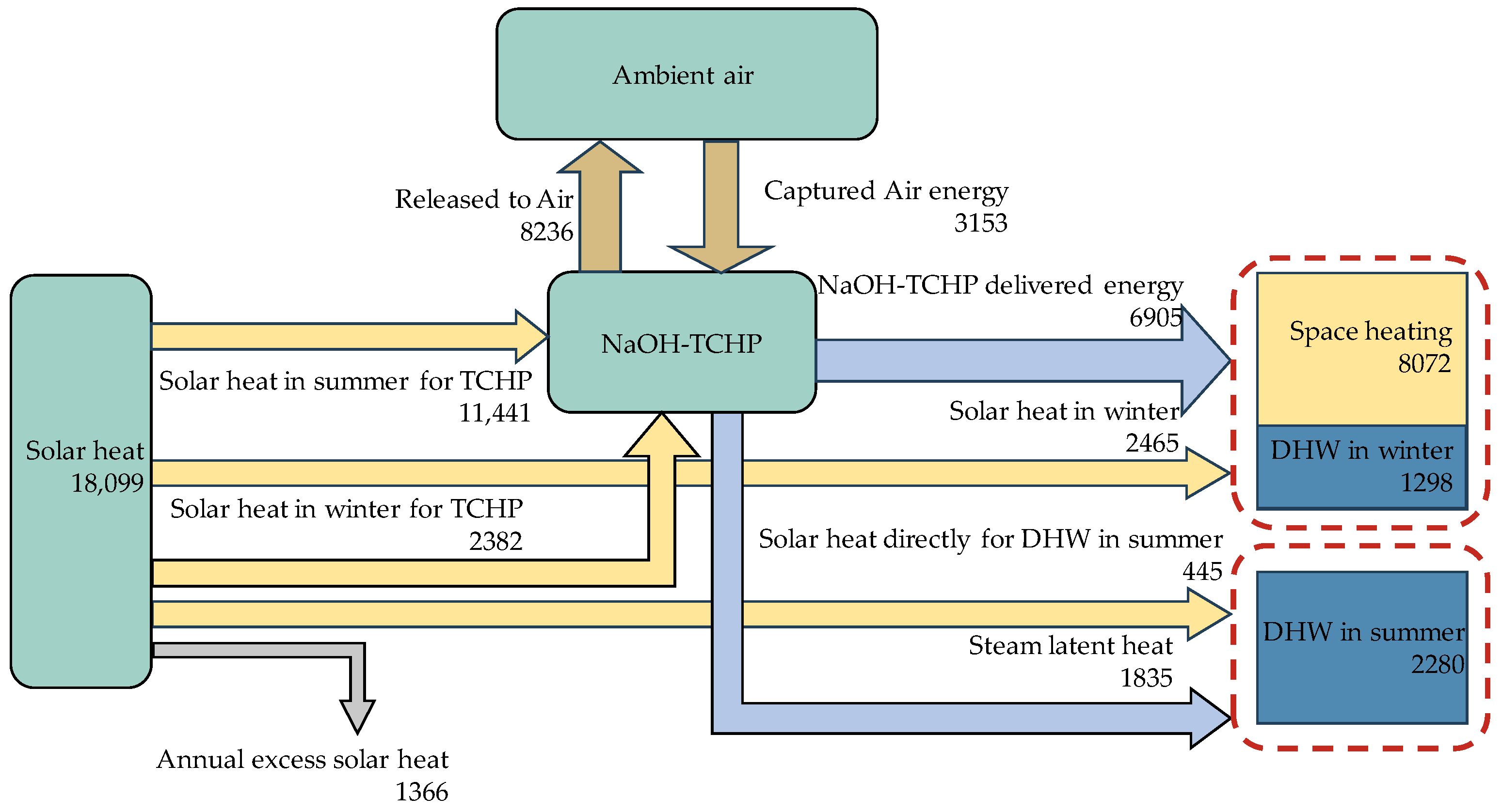
Figure 5 shows the energy flow in a charging–discharging cycle for the solar–NaOH TCHP system. A total of 18,099 kWh (winter, 5065 kWh; summer, 13,034 kWh) of solar energy can be collected. Approximately 63% (11,441 kWh) is used for charging. The NaOH HP delivers 6905 kWh of heating energy in the winter and 1835 kWh in the summer. System-wise, the total delivered heat is 11,650 kWh (winter, 9370 kWh; summer DHW, 2280 kWh). There is excessive solar heat that cannot be utilized in periods 1 to 4. This amounts to 1366 kWh (discharge period: 218 kWh, charge period: 1148 kWh). It is possible to minimize excessive solar heat through further optimization by adjusting the operation parameters, such as the divisions of periods, operation conditions, etc.
The ESD value and storage efficiency are calculated by Equations (26) and (27). The required storage volume is 10.48 tons (5.78 m3) of sorbent (70% wt solution), 13.97 tons (13.97 m3) of water, and 24.45 tons (18.5 m3) of discharged solution (30% wt solution). The theoretical maximum volume (discharged solution + water tank) is 32.47 m3. From Figure 5, the output of the discharging heat is = 6905 kWh. The input of the charging heat is = 11,441 kWh. As a result, the ESD based on the volume of discharged solution is 363 kWh/m3 and the storage efficiency is 0.61. The four-tank arrangement in Figure 1 is just one of the feasible schemes to store the solutions and condensing water. It is possible to optimize the storage to reduce the empty space in the tanks [12].
Table 2 displays the ESD values for some common working pairs in the literature. The value derived from this study ranks among the top values. However, cautions should be taken when comparing the ESD value with those in the literature, as the definition may vary. All listed references claim to use the same definition, except for sources 4 and 6. The values in source 4 are calculated based on the volume sum of the concentrated solution and the water, while the value in source 6 is calculated based on the volume sum of the diluted solution and the water. Including the water volume in Equation (26) would result in a modified ESD of 207 kWh/m3, which is still higher than the value from source 6.
The ESD value is also very much dependent on the boundary conditions. Therefore, the values for the same working pair of NaOH/H2O are compared. The value from this study is higher than that from source 2, which can be explained by the factor that a larger concentration difference between the charged solution and the discharged solution is used in this study. However, the value from source 3 is the highest, although the concentration difference or working range is not the greatest. Details of the calculation are not given in source 3, although it is claimed that the value is based on the discharged solution volume.
3.3. Space Performance
In building applications, installation space is an important factor. For a solar–NaOH heat pump system, the main consideration is the size of the collectors and the storage tank. For this purpose, the solar–NaOH TCHP system features several of the following novel designs: (1) a double-stage operation to enhance the energy storage density, (2) an integrated design to make full use of solar energy, both in the thermochemical operation cycles and direct solar heating, and (3) the cascaded use of condensing heat for summer DHW.
The double-stage design enables a greater concentration difference to be used without the need for a much higher discharging temperature. For a single-stage design, a working range from 30% to 70% would require a discharging temperature over 150 °C [37], which is practically impossible for conventional thermal collectors. The advantage of the double-stage strategy is also explored and verified for other working pairs, such as LiBr/H2O [35] and zeolite/H2O [50].
The full integration of solar heat makes more efficient use of the available solar collectors. To meet the winter heating demand, the system requires 14.3 tons of 70% solution (see the first point of the discharging line). However, it requires 48 m2 of collectors to regenerate the solution. The inclusion of these extra collectors in winter solar heating reduces the heating load for the TCHP system and hence the required solution mass. The converged results show that, after optimization, the full integration of solar heat can reduce the charged solution mass by 3.82 tons and the collector area by 12.5 m2.
The cascaded use of solar heat also helps reduce the need for the collector area. Out of the 11,441 kWh of the discharging heat, the system uses 1835 kWh of the condensing heat for summer DHW. This is helpful because the DHW load does not cause the need for additional collectors.
The space performance is compared with sensible seasonal storage. For the same building loads, Liu et al. [42] compared five solar systems in various combinations with STES, ASHP, and photovoltaic (PV) panels to meet both the cooling and heating demands. To meet the heating demand, conventional energy storage using water would need 40 m2 of collectors and 80 m3 of storage space. In comparison, the solar–NaOH TCHP system can reduce the collector area by 12.5% to 35.13 m2 and the storage space by 59% to 32.47 m3. However, the potential of the ASHP cannot be ignored in this climate. The best option is probably the photovoltaic/thermal (PV/T) + ASHP option, which only requires 40.6 m2 of installation area, and no major storage tanks are required [42]. In the future, more sophisticated integrations of the TCHP with other efficient technologies to meet building energy demand will remain as an interesting topic.
From Figure 5, the NaOH TCHP system extracts 3153 kWh of heat from the air source, which accounts for 34% of the total heating loads. The daily average amount is 26.6 kWh. A high ratio of air-sourced energy is advantageous because it reduces the required amount of solution and hence the size of the storage tanks. The disadvantage is that it may require a large heat exchanger, the space of which needs to be considered in practice. A more detailed dynamic simulation can facilitate the proper sizing of the heat exchangers.
4. Limitations and Future Studies
This study addresses the feasibility of a two-stage solar–NaOH heat pump heating system in building applications, with a focus on the space requirement. A static modeling approach was used. The study has the following limitations:
(1) The static model assumes an ideal heat and mass transfer process, neglecting all thermal losses and all heat and mass transfer resistances. In reality, there will be thermal losses at the reactors, storage tanks, and pipe works, although these losses can be minimized through proper insulation. When these losses are considered, the realizable storage density will be less than that obtained in this study. The required collector area will be larger, and the solution mass will be greater. In addition, the vapor transport between the reactors and the evaporator/condenser or heat transfer at the heat exchangers can limit the system’s heating capacity if these components are not sized properly. The thermal loss is dependent on the dynamic climatic data. Therefore, a more practical analysis shall be performed in a dynamic simulation process.
(2) As the main purpose of this study is to prove the concept and potential, the proposed system and operation strategy do not necessarily represent the optimized ones. Currently, the concentrated and diluted solutions are stored in two separate containers. A total of four tanks are used. In practice, further analysis can be performed to optimize the storage strategy for minimal empty space in the tanks. For example, it is possible to cut the tank volume in half by storing the water and the concentrated solution back into the emptied dilute tanks. Lowering the storage volume can significantly increase the ESD value. Optimizing the flow and storage strategies will be explored in the future for the minimal space required for the storage tanks.
(3) This study only considers space for collectors and tanks, leaving out relatively smaller components such as solar heating water tanks, reactors, and heat exchangers. In practice, an equipment room can accommodate these smaller components. In comparison, solar collectors and solution storage tanks are more space demanding. Firstly, the integration of solar collectors with buildings is more challenging due to the restrictions on building visual requirements and the availability of installation areas. Secondly, as a type of seasonal energy storage, the chemical solution tank is typically large and requires much more additional space. Nevertheless, all components need to be considered in a holistic system plan.
(4) The study does not account for the necessary cooling in the hot summer and cold winter regions. It is possible to use a solar–NaOH chemical heat pump for cooling. The integration of cooling will require more solar collectors and maybe a slight increase in solution mass. And it is possible that both cooling and heating share the same pipework and components. Alternatively, cooling can be provided by the PV + ASHP system, which is more compact and also technologically mature. The choice needs further analysis. The feasibility of using the NaOH chemical heat pump for cooling in summer, along with system construction, will be explored in subsequent research.
In addition, the NaOH solution is known to be corrosive. In the literature, the use of specially treated stainless steel is recommended [37], which adds to the material cost. The system stability of long-term operations requires more studies.
5. Conclusions
This study addresses the feasibility of a two-stage solar–NaOH heat pump heating system in building applications, with a focus on the space requirement. The following conclusions can be made.
(1) The double-stage design of the system can work in a greater concentration difference (40% wt = 70% wt − 30% wt) for the climate in hot summer and cold winter regions in China. The discharging heat can be provided by conventional non-concentrated solar heat. The achieved energy storage density based on the discharged solution is 363 kWh/m3.
(2) For the studied single-family house, the proposed solar–NaOH heat pump heating system requires 35.13 m2 of collectors and 32.47 m3 of storage tanks. Compared with the sensible seasonal storage, the collector area is reduced by 12.5% and the storage space is reduced by 59%, with a possible further reduction through optimization.
(3) The collectors sized for discharging the solution during non-heating seasons can also produce a significant amount of solar heat for heating in winter. It is important to optimize the sizing of the system by considering this available solar heat in winter. The optimization reduces 3.82 tons of charged solution and 12.5 m2 of the collector area.
In the future, a more detailed dynamic simulation is needed with a focus on system optimization and other challenges that may be present in the heat and mass exchangers.
Author Contributions
Conceptualization, G.H.; methodology, Y.S. and G.H.; software, Y.S.; validation, Y.S., G.H. and R.L.; formal analysis, Y.S.; investigation, Y.S.; resources, G.H., Y.Y. and D.D.; data curation, Y.S.; writing—original draft preparation, Y.S. and G.H.; writing—review and editing, R.L. and G.H.; visualization, Y.S.; supervision, G.H.; project administration, G.H.; funding acquisition, G.H. and Y.Y. All authors have read and agreed to the published version of the manuscript.
Funding
This research was funded by the Center for Balance Architecture, Zhejiang University.
Data Availability Statement
The original contributions presented in the study are included in the article, further inquiries can be directed to the corresponding author.
Conflicts of Interest
The authors declare no conflicts of interest.
Nomenclature
| Subscript | Meaning | Terminology | Meaning |
| a | Ambient air | A | Collector area |
| c | Concentrated solution | ESD | Energy storage density |
| ch | Thermochemical energy | h | Specific enthalpy, kJ/kg |
| charging | Charging | m | Mass flow |
| d | Dilute solution | Q | Heat flux, kW |
| DHW | Domestic hot water | q | Heat flux, kW/kg |
| dis | Desorption, discharge | T | Temperature |
| load | Heating load | Storage efficiency | |
| solar | Solar heat need | Collector efficiency | |
| sp | Space heating | ||
| stc | Collected solar heat | ||
| vp | Vapor | ||
| w | Water | ||
| 1, …, 5 | Period no. |
References
- IEA. Final Energy Consumption in the Buildings Sector. 2021. Available online: https://www.iea.org/data-and-statistics/charts/final-energy-consumption-in-the-buildings-sector-2021 (accessed on 12 January 2024).
- Mehari, A.; Xu, Z.Y.; Wang, R.Z. Thermodynamic evaluation of three-phase absorption thermal storage in humid air with energy storage density over 600 kWh/m3. Energy Convers. Manag. 2022, 258, 115476. [Google Scholar] [CrossRef]
- Li, Q.; Liu, J.; Wang, S.; Guo, Y.; Han, X.; Li, Q.; Cheng, Y.; Dong, Z.; Li, X.; Zhang, X. Numerical insights into factors affecting collapse behavior of horizontal wellbore in clayey silt hydrate-bearing sediments and the accompanying control strategy. Ocean Eng. 2024, 297, 117029. [Google Scholar] [CrossRef]
- Li, Q.; Wang, F.; Wang, Y.; Bai, B.; Zhang, J.; Lili, C.; Sun, Q.; Wang, Y.; Forson, K. Adsorption behavior and mechanism analysis of siloxane thickener for CO2 fracturing fluid on shallow shale soil. J. Mol. Liq. 2023, 376, 121394. [Google Scholar] [CrossRef]
- Bundschuh, J.; Kaczmarczyk, M.; Ghaffour, N.; Tomaszewska, B. State-of-the-art of renewable energy sources used in water desalination: Present and future prospects. Desalination 2021, 508, 115035. [Google Scholar] [CrossRef]
- Perez-Mora, N.; Bava, F.; Andersen, M.; Bales, C.; Lennermo, G.; Nielsen, C.; Furbo, S.; Martínez-Moll, V. Solar district heating and cooling: A review. Int. J. Energy Res. 2018, 42, 1419–1441. [Google Scholar] [CrossRef]
- Liu, Z.; Liu, Y.; He, B.J.; Xu, W.; Jin, G.; Zhang, X. Application and suitability analysis of the key technologies in nearly zero energy buildings in China. Renew. Sustain. Energy Rev. 2019, 101, 329–345. [Google Scholar] [CrossRef]
- IEA. Technology and Innovation Pathways for Zero-Carbon-Ready Buildings by 2030. Paris. 2022. Available online: https://www.iea.org/reports/technology-and-innovation-pathways-for-zero-carbon-ready-buildings-by-2030 (accessed on 12 January 2024).
- Ucar, A.; Inalli, M. Thermal and economic comparisons of solar heating systems with seasonal storage used in building heating. Renew. Energy 2008, 33, 2532–2539. [Google Scholar] [CrossRef]
- Hongois, S.; Kuznik, F.; Stevens, P.; Roux, J.J. Development and characterisation of a new MgSO4-zeolite composite for long-term thermal energy storage. Sol. Energy Mater. Sol. Cells 2011, 95, 1831–1837. [Google Scholar] [CrossRef]
- Palomba, V.; Frazzica, A. Application of numerical methods for the design of thermocline thermal energy storage: Literature review and critical analysis. J. Energy Storage 2022, 46, 103875. [Google Scholar] [CrossRef]
- Quinnell, J.A.; Davidson, J.H.; Burch, J. Liquid calcium chloride solar storage: Concept and analysis. In Proceedings of the ASME 2010 4th International Conference on Energy Sustainability, Phoenix, AZ, USA, 17–22 May 2010; Volume 2, pp. 715–724. [Google Scholar] [CrossRef]
- Sunku Prasad, J.; Muthukumar, P.; Desai, F.; Basu, D.N.; Rahman, M.M. A critical review of high-temperature reversible thermochemical energy storage systems. Appl. Energy 2019, 254, 113733. [Google Scholar] [CrossRef]
- Guanghui, L.; Hui, C.; Hao, P.; Chun, C.; Yaxuan, X.; Zhu, J.; Lin, C.; Yanqi, Z.; Gan, Z.; Geng, Q.; et al. The new research progress of thermal energy storage materials. Energy Storage Sci. Technol. 2017, 6, 1058. [Google Scholar] [CrossRef]
- Pardo, P.; Anxionnaz-Minvielle, Z.; Rougé, S.; Cognet, P.; Cabassud, M. Ca(OH)2/CaO reversible reaction in a fluidized bed reactor for thermochemical heat storage. Sol. Energy 2014, 107, 605–616. [Google Scholar] [CrossRef]
- Hao, M.; Liu, H.; Wang, W. Research progress of hydrated salt thermochemical heat storage materials. Energy Storage Sci. Technol. 2020, 9, 791–796. [Google Scholar]
- Ding, Y.; Riffat, S.B. Thermochemical energy storage technologies for building applications: A state-of-the-art review. Int. J. Low-Carbon Technol. 2013, 8, 106–116. [Google Scholar] [CrossRef]
- Lahmidi, H.; Mauran, S.; Goetz, V. Definition, test and simulation of a thermochemical storage process adapted to solar thermal systems. Sol. Energy 2006, 80, 883–893. [Google Scholar] [CrossRef]
- Stitou, D.; Mazet, N.; Mauran, S. Experimental investigation of a solid/gas thermochemical storage process for solar air-conditioning. Energy 2012, 41, 261–270. [Google Scholar] [CrossRef]
- Zondag, H.A. Sorption Heat Storage. In Solar Energy Storage; Elsevier Inc.: Amsterdam, The Netherlands, 2015; pp. 135–154. [Google Scholar] [CrossRef]
- Yu, N.; Wang, R.Z.; Wang, L.W. Sorption thermal storage for solar energy. Prog. Energy Combust. Sci. 2013, 39, 489–514. [Google Scholar] [CrossRef]
- N’Tsoukpoe, K.E.; Le Pierrès, N.; Luo, L. Experimentation of a LiBr-H2O absorption process for long-term solar thermal storage: Prototype design and first results. Energy 2013, 53, 179–198. [Google Scholar] [CrossRef]
- Li, T.X.; Wu, S.; Yan, T.; Wang, R.Z.; Zhu, J. Experimental investigation on a dual-mode thermochemical sorption energy storage system. Energy 2017, 140, 383–394. [Google Scholar] [CrossRef]
- Palomba, V.; Sapienza, A.; Aristov, Y. Dynamics and useful heat of the discharge stage of adsorptive cycles for long term thermal storage. Appl. Energy 2019, 248, 299–309. [Google Scholar] [CrossRef]
- Xu, S.Z.; Wang, R.Z.; Wang, L.W.; Zhu, J. Performance characterizations and thermodynamic analysis of magnesium sulfate-impregnated zeolite 13X and activated alumina composite sorbents for thermal energy storage. Energy 2019, 167, 889–901. [Google Scholar] [CrossRef]
- Xu, J.X.; Li, T.X.; Chao, J.W.; Yan, T.S.; Wang, R.Z. High energy-density multi-form thermochemical energy storage based on multi-step sorption processes. Energy 2019, 185, 1131–1142. [Google Scholar] [CrossRef]
- Scapino, L.; Zondag, H.A.; Van Bael, J.; Diriken, J.; Rindt, C.C.M. Sorption heat storage for long-term low-temperature applications: A review on the advancements at material and prototype scale. Appl. Energy 2017, 190, 920–948. [Google Scholar] [CrossRef]
- Mehari, A.; Xu, Z.Y.; Wang, R.Z. Thermal energy storage using absorption cycle and system: A comprehensive review. Energy Convers. Manag. 2020, 206, 112482. [Google Scholar] [CrossRef]
- Kant, K.; Pitchumani, R. Advances and opportunities in thermochemical heat storage systems for buildings applications. Appl. Energy 2022, 321, 119299. [Google Scholar] [CrossRef]
- Ji, L.; Shukla, S.K.; Zuo, Z.; Lu, X.; Ji, X.; Wang, C. An overview of the progress of new working pairs in absorption heat pumps. Energy Rep. 2023, 9, 703–729. [Google Scholar] [CrossRef]
- Frazzica, A.; Freni, A. Adsorbent working pairs for solar thermal energy storage in buildings. Renew. Energy 2017, 110, 87–94. [Google Scholar] [CrossRef]
- Donkers, P.A.J.; Sögütoglu, L.C.; Huinink, H.P.; Fischer, H.R.; Adan, O.C.G. A review of salt hydrates for seasonal heat storage in domestic applications. Appl. Energy 2017, 199, 45–68. [Google Scholar] [CrossRef]
- Li, Z.; Xu, M.; Huai, X.; Huang, C.; Wang, K. Simulation and analysis of thermochemical seasonal solar energy storage for district heating applications in China. Int. J. Energy Res. 2021, 45, 7093–7107. [Google Scholar] [CrossRef]
- Gao, P.; Wang, L. Investigation on the air-source chemisorption heat pump for the severely cold regions. Appl. Therm. Eng. 2020, 179, 115694. [Google Scholar] [CrossRef]
- Gao, J.T.T.; Xu, Z.Y.Y.; Wang, R.Z.Z. Experimental study on a double-stage absorption solar thermal storage system with enhanced energy storage density. Appl. Energy 2020, 262, 114476. [Google Scholar] [CrossRef]
- Tzinnis, E.; Baldini, L. Combining sorption storage and electric heat pumps to foster integration of solar in buildings. Appl. Energy 2021, 301, 117455. [Google Scholar] [CrossRef]
- Weber, R.; Dorer, V. Long-term heat storage with NaOH. Vacuum 2008, 82, 708–716. [Google Scholar] [CrossRef]
- Fumey, B.; Baldini, L.; Borgschulte, A. Water Transport in Aqueous Sodium Hydroxide Films for Liquid Sorption Heat Storage. Energy Technol. 2020, 8, 2000187. [Google Scholar] [CrossRef]
- Fumey, B.; Weber, R.; Baldini, L. Liquid sorption heat storage—A proof of concept based on lab measurements with a novel spiral fined heat and mass exchanger design. Appl. Energy 2017, 200, 215–225. [Google Scholar] [CrossRef]
- Fumey, B.; Weber, R.; Gantenbein, P.; Daguenet-Frick, X.; Stoller, S.; Fricker, R.; Dorer, V. Operation results of a closed sorption heat storage prototype. Energy Procedia 2015, 73, 324–330. [Google Scholar] [CrossRef]
- Fumey, B.; Baldini, L. Static temperature guideline for comparative testing of sorption heat storage systems for building application. Energies 2021, 14, 3754. [Google Scholar] [CrossRef]
- Liu, R.; He, G.; Su, Y.; Yang, Y.; Ding, D. Solar energy for low carbon buildings: Choice of systems for minimal installation area, cost, and environmental impact. City Built Environ. 2023, 1, 16. [Google Scholar] [CrossRef]
- Zhou, L. Experimental Study on Performance of Solar Collector in Solar Membrane Distillation System. Master’s Thesis, Inner Mongolia University of Technology, Hohhot, China, 2009. [Google Scholar]
- Wagner, W.; Cooper, J.R.; Dittmann, A. The IAPWS Industrial Formulation 1997 for the Thermodynamic Properties of Water and Steam; Springer: Berlin/Heidelberg, Germany, 1997. [Google Scholar]
- Zaytsev, I.D.; Aseyev, G.G. Properties of aqueous solutions of electrolytes. Choice Rev. Online 1993, 30, 30–4415. [Google Scholar] [CrossRef]
- Chen, H. A correlation of sodium hydroxide enthalpy. Chem. Eng. 1991, 19, 79. [Google Scholar]
- Zhang, X.; Li, M.; Shi, W.; Wang, B.; Li, X. Experimental investigation on charging and discharging performance of absorption thermal energy storage system. Energy Convers. Manag. 2014, 85, 425–434. [Google Scholar] [CrossRef]
- Yu, N.; Wang, R.Z.; Lu, Z.S.; Wang, L.W.; Ishugah, T.F. Evaluation of a three-phase sorption cycle for thermal energy storage. Energy 2014, 67, 468–478. [Google Scholar] [CrossRef]
- Yu, N.; Wang, R.Z.; Lu, Z.S.; Wang, L.W. Study on consolidated composite sorbents impregnated with LiCl for thermal energy storage. Int. J. Heat Mass Transf. 2015, 84, 660–670. [Google Scholar] [CrossRef]
- Köll, R.; van Helden, W.; Engel, G.; Wagner, W.; Dang, B.; Jänchen, J.; Kerskes, H.; Badenhop, T.; Herzog, T. An experimental investigation of a realistic-scale seasonal solar adsorption storage system for buildings. Sol. Energy 2017, 155, 388–397. [Google Scholar] [CrossRef]
Figure 1.
Operation principles of the two-stage solar–NaOH heat pump heating system and the corresponding P-T diagrams. (1) to (5) are five operation modes for different periods.
Figure 1.
Operation principles of the two-stage solar–NaOH heat pump heating system and the corresponding P-T diagrams. (1) to (5) are five operation modes for different periods.

Figure 2.
Ambient temperature, solar radiation, and heating demand.

Figure 3.
TRNSYS model for determining the capacity of the solar collectors in the specific period.

Figure 4.
Solution convergency during the iterative process.

Figure 5.
Annual energy flow in the NaOH TCHP system (units: kWh).


Table 1.
Summary of climate parameters for the five periods.
| Period No. | Dates | Ambient Temp, , °C | Collector Production Rate, qstc (kWh/m2) | Heating Load , kWh |
|---|---|---|---|---|
| 1 | 15 November–27 November | 11.4 | 14.3 | = 218.20 |
| 2 | 28 November–15 March | 6.7 | 137.1 | = 9151.95 |
| 3 | 15 March–31 July | 22.7 | 225.3 | = 1368.77 |
| 4 | 1 August–30 September | 27.0 | 101.0 | = 466.20 |
| 5 | 1 October–11 November | 18.0 | 44.8 | = 445.06 |
Table 2.
Performance comparison of thermochemical absorption heat storage.
| Working Pair | Reaction Condition | Energy Storage Density, kWh/m3 | Sources |
|---|---|---|---|
| NaOH/H2O | 30 wt% to 70 wt% | 363 | 1. This study |
| NaOH/H2O | 45 wt% to 70 wt% | 257 | 2. [37] |
| NaOH/H2O | 25 wt% to 50 wt% | 435 | 3. [39] |
| CaCl2/H2O | 91~93 (*) | 4. [12] | |
| LiBr/H2O | 226~252 | 5. [22] | |
| LiBr/H2O | 110 (**) | 6. [47] | |
| LiCl/H2O | Crystallization is allowed | 668 | 7. [48,49] |
* Based on the volume sum of the charged solution and the water. ** Based on the volume sum of the discharged solution and the water.
Disclaimer/Publisher’s Note: The statements, opinions and data contained in all publications are solely those of the individual author(s) and contributor(s) and not of MDPI and/or the editor(s). MDPI and/or the editor(s) disclaim responsibility for any injury to people or property resulting from any ideas, methods, instructions or products referred to in the content. |
© 2024 by the authors. Licensee MDPI, Basel, Switzerland. This article is an open access article distributed under the terms and conditions of the Creative Commons Attribution (CC BY) license (https://creativecommons.org/licenses/by/4.0/).
Share and Cite
MDPI and ACS Style
Su, Y.; Yang, Y.; He, G.; Liu, R.; Ding, D. Two-Stage Solar–NaOH Thermochemical Heat Pump Heating System for Building Heating: Operations Strategies and Theoretical Performance. Energies 2024, 17, 1976. https://doi.org/10.3390/en17081976
AMA Style
Su Y, Yang Y, He G, Liu R, Ding D. Two-Stage Solar–NaOH Thermochemical Heat Pump Heating System for Building Heating: Operations Strategies and Theoretical Performance. Energies. 2024; 17(8):1976. https://doi.org/10.3390/en17081976
Chicago/Turabian StyleSu, Yujie, Yi Yang, Guoqing He, Renhua Liu, and De Ding. 2024. "Two-Stage Solar–NaOH Thermochemical Heat Pump Heating System for Building Heating: Operations Strategies and Theoretical Performance" Energies 17, no. 8: 1976. https://doi.org/10.3390/en17081976
Note that from the first issue of 2016, this journal uses article numbers instead of page numbers. See further details here.