
Study of Energy Flow Mechanisms in High Power Device Converters


1
School of Electrical and Information Engineering, Zhengzhou University, Zhengzhou 450001, China
2
School of Physics, Zhengzhou University, Zhengzhou 450001, China
*
Author to whom correspondence should be addressed.
Energies 2024, 17(8), 1980; https://doi.org/10.3390/en17081980
Submission received: 19 March 2024
/
Revised: 13 April 2024
/
Accepted: 17 April 2024
/
Published: 22 April 2024
(This article belongs to the Section F1: Electrical Power System)
Abstract
:The work in this paper is applied to the Zhangbei Power grid. In the flexible direct current (DC) power system, the fault current rises extremely fast when a DC fault occurs. The requirements for the peak of breaking current and fault energy absorption of DC circuit breakers (DCCBs) increase linearly, which significantly increases the cost of the equipment. Therefore, in order to reduce the design difficulty of DCCBs, this paper proposes a strategy to control energy after the fault occurs. Firstly, the energy dimension is added on the basis of the traditional vector control of MMC, which constitutes a three-dimensional energy direct control. Subsequently, the architectures of energy fluctuation control and feedforward control are proposed. The influencing mechanisms for the peak fault current, peak fault voltage and energy dissipation are analyzed. Finally, the simulation of energy fluctuation control and feedforward control is constructed on PSCAD/EMTDC. The simulation results show that the energy fluctuation control is obviously better than the conventional three-dimensional energy control, and the feedforward energy control is further improved on this basis. Compared with the conventional vector control, the peak energy is reduced by 45.43% and the peak current is reduced by 25.39%, which helps to simplify the equipment design and reduce the equipment cost.
1. Introduction
Compared with the grid power phase change control technology and voltage source converter type high voltage DC transmission system, Flexible DC transmission technology based on a modular multilevel converter (MMC) [1,2,3] has outstanding capabilities in the structure of the network, power decoupling control and other aspects [4,5], as well as the lack of possibility of phase change failure. It has obvious advantages in solving the new energy grid in inland areas, offshore wind power, and long-distance transmission. So far, MMC-HVDC has developed rapidly, and more than 20 MMC projects [6,7,8,9] have been built at home and abroad. As the demand for voltage level increases, the energy control requirements for flexible DC transmission are also increasing.
The MMC [10,11,12,13,14] control system is divided into three parts, which are system level control, converter level control and valve level control [15], in which the converter level is mainly used for active and re-energy fluctuation control, DC voltage control and so on. The current MMC project’s converter (a two-level voltage source converter, 2L-VSC) adopts the double closed-loop vector control derived from the two-level voltage source converter. According to the instantaneous reactive power theory, the generation of modulation signals for the converter is based on the outer-loop control of active and reactive electrical quantities and the inner-loop control of the alternating direct (dq) axis currents. During operation, the MMC three-phase six-bridge is basically in the state of conduction, but due to the dynamic casting of sub-module capacitance between the phase units, it will generate circulating current. In order to inhibit the circulating current as well as the impact of circulating current generation, it should often be equipped with a circulating current suppressor based on the double-closed-loop vector control as well as the valve-level sub-module capacitance voltage equalization control.
At present, scholars at home and abroad have actively explored in synthesizing the advantages of double closed-loop vector control and energy control, and the literature [16] proposes to reduce the fluctuation of sub-module capacitance voltage by fundamental frequency rotation coordinate systems and second harmonic rotation coordinate systems. The literature [17] proposes the introduction of phase unit submodule capacitance energy control to reduce submodule capacitance voltage fluctuations. The literature [18] introduced the dqz transform and designed the outer loop sub-module capacitance energy control and inner loop z-axis current control to improve the small signal stability of MMC. However, there is still room for further reduction of the breaker energy consumption peak and fault current peak. The literature [19,20] introduced energy control to analyze the DC voltage response and AC voltage network control of MMC, respectively. This control method can reduce the peak of fault current and the peak of energy consumption of the arrester well, which has great practical significance for the simplification of equipment design and the reduction of cost. Reference [21] proposes to optimize the control strategy of MMC by combining SOC equalization control with DC link voltage control. The precision of SOC control is improved, but the efficiency of the SOC equalization control strategy is relatively low. The literature [22] proposes to detect the internal condition of the sub-module by estimating the capacitance value in the sub-module through Recursive Least Square (RLS) algorithm, and the literature [23] introduces a no-power-drop control model to realize the regulation characteristics by establishing the equation of the extended power flow. The literature [24] proposes a DCCB and flc coordinated method to suppress or remove DC fault currents, which has less interference to the AC system, but the equipment cost is high. The literature [25] proposes a new approach to system modeling that reduces energy pulsations by 44% but focuses mainly on the process of stable operation rather than fault conditions, and the literature [20] proposes a feed-forward control method in series-compensated wireless power transfer systems, which is an important reference for the optimization of MMC-HVDC control systems. The existing literature mainly focuses on reducing the time of suppressing or removing the fault current, and there are fewer studies on the increase in fault capacity of DCCB caused by the rapid increase in breaking fault current when the circuit breaker opens. This paper proposes an energy feedforward control method that reduces the fault capacity of DCCB while reducing the time of suppressing and removing the fault current.
The half-bridge MMC [26] with DC circuit breakers (DCCB) scheme uses the DCCBs to break the fault line after a DC fault occurs. However, the fault current rises sharply after a few milliseconds of fault occurs, which increases the difficulty of DCCBs’ breaking capability. The larger the breaking current of DCCB, the more power electronic devices and the higher the construction cost are required [27,28,29,30], and the complexity of equipment design is increased.
Based on the above research background, Section 2 introduces the basic structure and control mechanisms of traditional energy control. In order to reduce the peak fault current and energy dissipation, direct energy control and feedforward energy control are proposed in Section 3 and Section 4, respectively. And the control mechanisms are introduced. In Section 5, simulation experiments are conducted to compare the peak energy consumption of conventional vector control circuit breakers with the peak fault current and then verify the effectiveness and feasibility of the proposed energy control strategy.
2. Flexible DC Transmission System Energy Control
2.1. Traditional MMC Energy Control
The half-bridge MMC topology is shown in Figure 1. Where Idc is the DC current, DC output voltage, is the equivalent resistance of the bridge, is the bridge impedance, is the sub-module capacitance, is the rated voltage of the sub-module capacitance, , respectively, is the upper and lower bridge currents of the jth phase (j = A, B, C), is the upper and lower bridge output voltages of the jth phase, respectively; is the phase current of the valve side, is the reactance of the AC system, and is the AC system phase voltage.
The sum of the capacitance voltages of the upper and lower bridge sub-modules of the MMC is and , respectively, and the capacitance storage energy of the upper and lower bridge sub-modules can be obtained from the following equation as
From Equations (1) and (2), N is the number of sub-modules in each phase of the bridge (without redundancy). The common mode and differential mode components of the total capacitive energy of the upper and lower bridge can be deduced as:
Denote the common mode component of the j-phase bridge current as Icirjj:
Based on Equations (5) and (6), is defined as follows:
Based on Equations (5)–(7), we can design the energy control loop for each phase unit as shown in Figure 2a.
2.2. Three Dimensional Energy Control Design
The MMC energy control shown in Figure 2a [26] is relatively complex and needs to be improved in terms of control performance. Based on the above problems, this section designs a three-dimensional energy control architecture suitable for MMC and introduces the process of energy control in terms of both a fixed power station and a fixed DC voltage station, as shown in Figure 2b.
- Constant power station control
For the MMC, the rate of change in the stored energy of the capacitance of all its internal sub-modules is the difference between the AC and DC power, i.e.,
where Pac and Pdc are the AC and DC power of the MMC, respectively. It can be obtained by bringing in Equation (9):
In the 2L-VSC, the bridge of the converter has no primitive for energy storage, and the AC and DC power can be considered to be balanced in real time (Pac = Pbc). However, numerous submodules provide energy buffering to the MMC. According to Equation (9), the capacitive storage energy of the submodules can be utilized to change the DC side power/current. Therefore, here we control the sub-module capacitance energy-DC current outer loop with the help of:
In Equation (10), ki and kp are the proportional coefficients of the proportional integral (PI) controller, respectively, PI controller control loop input controller is the actual energy and rated energy difference, by adjusting the proportion and integration, output control loop DC current.
3. Energy Fluctuation Control
In the face of surplus power in an AC fault in the MMC-HVDC. There are usually two directions of solution. One is to resolve the excess energy through energy dissipation devices [7]. The other is to absorb the extra power through an energy storage device and release it after the fault is cleared [8]. Compared with the two, the former wastes more energy. The energy use efficiency is lower, and the economic benefits are softer. Therefore, we chose the energy storage solution.
The basis of the energy storage scheme is the energy storage device. In the MMC-HVDC system, the energy storage device is mainly the capacitor and inductor. The capacitor’s energy storage capacity is much better than that of the inductor, so the capacitor is the primary energy storage device in the system, so we mainly consider the capacitive energy of the MMC. The following two control methods are explained, respectively, and we conduct a comparative analysis.
- (a)
- Energy control for fixed power stations
For a single capacitor, the energy is expressed as shown in the following equation at rated conditions:
where is the capacity, and is the rated voltage.
Based on Equation (11), we can derive the sum of the capacitive energies of the individual bridge in the system:
Based on Equation (12), x can be a, b, c, and N is the number of sub-module capacitors on a single bridge. is the sum of the energy of a single bridge, and the sum of the power of three bridges gives the sum of the overall energy of the system:
Based on Equation (13), we obtain the sum of all the capacitive energy in the system , and the rate of change in is the difference between AC and DC power:
When the sub-module AC power is constant, we know that the change in energy change rate will cause the evolution of DC power, and the change in DC power is mainly reflected in the evolution of DC current. Based on Equation (14), we can control the DC power and thus the DC current by controlling the sum of the capacitance energy of the system through the PI controller:
In Equation (15), and are the proportional and integral coefficients of the PI controller in the energy controller, respectively. From Equation (15), we can obtain the effect of the energy change on the DC current and then on the whole system.
- (b)
- Fixed DC voltage station control
We control the DC power in traditional MMC energy control by controlling the current, which in turn controls the energy of the system. This idea can be applied to DC voltage stations.
When DC voltage and DC current are controlled:
where is the equivalent capacitance in the transmission line, and is the inlet current. When is kept constant, we can control this system by changing causing a change in .
Using Equation (16), we calculate the relationship between and , and we can control indirectly by controlling with the PI controller:
From Equation (17), is the actual value of DC voltage, and is the reference value. and are the proportional and integral coefficients of the PI controller in the DC voltage control loop, respectively.
From Equation (9), we can determine the relationship between the control loop current of the fixed power station and the control loop current of the DC voltage station, and the two will not conflict.
When and are controlled and brought into Equation (2), we establish the relationship between the d’ axis current and energy :
From Equation (18), and are the proportional and integral coefficients of the PI controller in the energy control loop. Based on Equation (18), we can control the d-axis current by controlling the total capacitance energy of the control module and then holding the whole system.
4. Feed-Forward Energy Control
Feed-forward control of energy can be achieved by superimposing a feed-forward signal on the rated energy stored in the original capacitor. When is greater than , the signal input to the energy PI controller is negative, the feed-forward control outputs a negative value, and the energy in the sub-module capacitor is reduced. The energy in the submodule capacitor at this time is shown in the following equation:
In feed-forward control, under normal circumstances, the system Kp and Ki in Equation (19) are the proportional and integral coefficients of the P controller in the energy control loop, respectively. To ensure the regular operation of the system, we have to make sure that the adaptive flow control does not interfere with the energy in the capacitance of the submodule, and the solution is to set to the maximum DC current in the case of being operated, which ensures that the difference between and is always positive. When an over-current is detected, the difference between and is negative, reducing the energy in the sub-module capacitors, the effect of which is determined by the integrating link. If the over-current persists, it is foreseeable that the PI controller will gradually reach the lower limit of , and is close to 0. The idea of adjusting the PI parameters in this paper is to provide a buffer space for the impact of the blocking by reducing the actual energy in the sub-module capacitance. Meanwhile, the control strategy improves to reduce the average energy in the sub-modules to regulate the fault, independent of the increase or decrease in the number of sub-modules.
5. Validate
With the continuous development of power electronic device manufacturing technology, the current flow capacity of IGBT devices has reached 5 kA and is widely used in wind farms, photovoltaics and other new energy transmission. The IGBT of this type of high-power device has a direct impact on the energy flow inside the converter station. Based on the above theoretical analysis, this section will analyze the fault characteristics of 4.5 kV/5 kA high-power devices applied in the Zhangbei Power Grid from the perspectives of energy fluctuation control and energy feed-forward control.
5.1. Simulation Results of Energy Fluctuation Control
A 750 MW/500 kV a four-terminal DC grid based on 4.5 kV/5 kA IGBTs is established on the basis of PSCAD/EMTDC, which is based on the positive half-loop model of Zhangbei power station [20]. As shown in Figure 3, the reference values of each valve control volume at both ends of the converter are Udcref = 500 kV, Pref = 750 MW, and Qref = 0 Mvar, as shown in Table 1. In the following, we set the DC current to be Idc and the AC current to be Iac. The detailed system parameters are shown in Table 2.
5.2. Simulation Results of Re-Energy Fluctuation Control
In order to explore the impact of energy feed-forward control on energy flow inside the converter station, this section studies the fault characteristics of the four terminal power grids under energy feed-forward control, and the system parameters are still shown in Table 2.
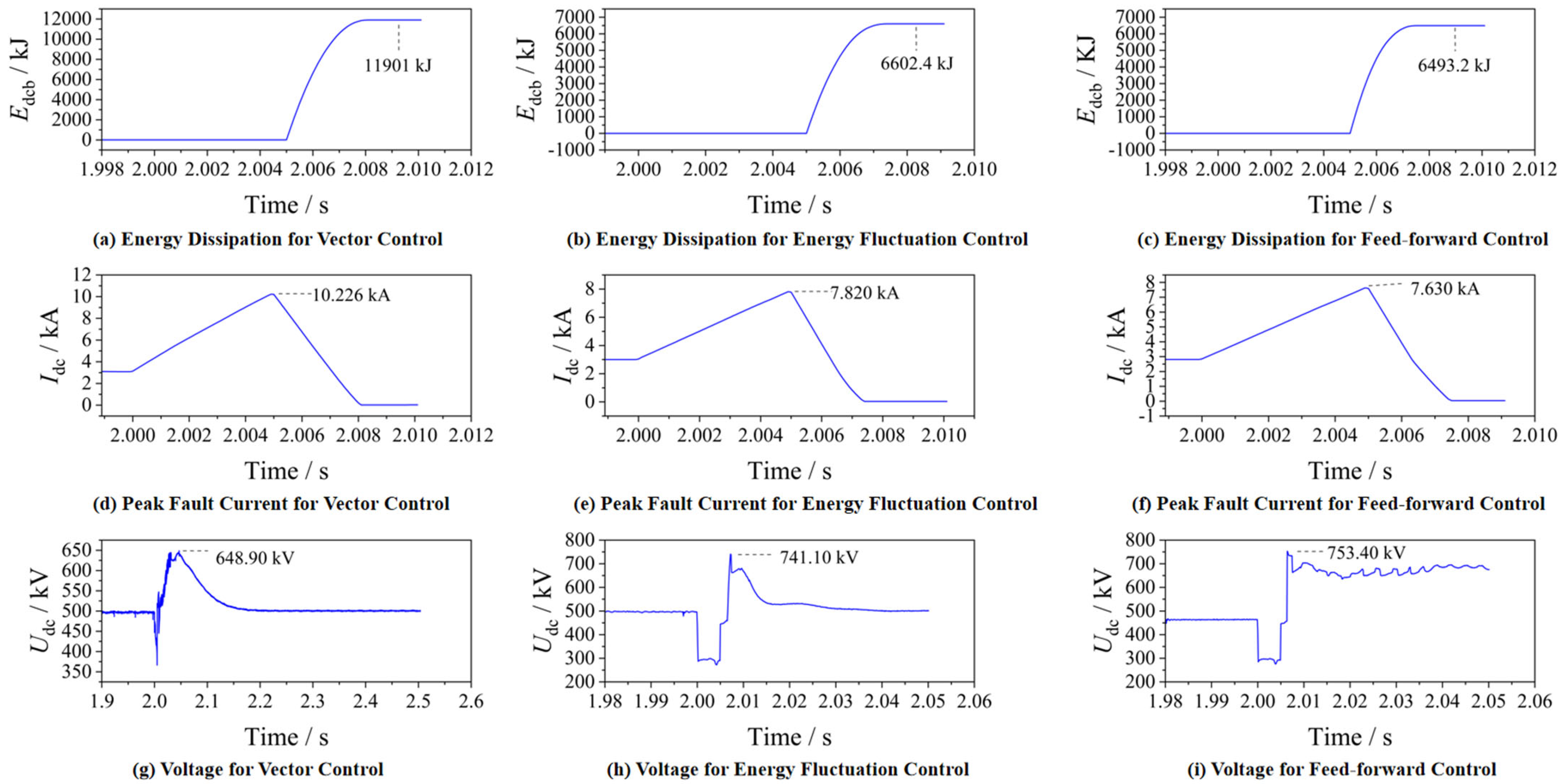
Figure 4a,d,g shows the simulation results of the four-terminal DC grid with the classical vector control strategy and Figure 4c,f,i shows the simulation results of the system with the feed-forward energy control strategy.
From Figure 4d, it can be seen that when the fault occurs, Idc has a rapid jump instantly. When the DCCB is turned off at 5 ms, Idc reaches a peak value of 10.226 kA, and the energy-consuming branch in the DCCB starts to consume energy. From Figure 4a, when the fault is cleared after 5 ms, the power consumed by the arrester in DCCB reaches a peak value of 11.901 kJ with feed-forward energy fluctuation control. From Figure 4f, the DCCB operates 5 ms after the fault occurs, and Idc reaches a peak of 7.630 kA, which is a reduction of 25.38%. From Figure 4i, 5 ms after the fault has been lifted, the energy consumed by the arrester reaches a peak value of 6.493 MJ. The energy consumed by the arrester reaches a peak value of 6.493 MJ, a reduction of 45.43%.
Based on the above analysis, it can be seen that energy feedforward control has a more significant suppression effect on energy fluctuations. Through the feedforward link, energy can be better controlled near the rated value, greatly reducing the energy absorbed by the lightning arrester and improving the operating characteristics of the circuit breaker [31].
Figure 3 shows the schematic diagram of the simulated system. Table 1, Table 2 and Table 3 are the original parameters. The system is simulated and analyzed under conventional dual vector and energy fluctuation control, respectively. MMC1 is a rectifier. Iac is controlled by energy fluctuation control and re-energy fluctuation control, and Idc is controlled by active re-energy fluctuation control. MMC4 is an inverter. Iac is controlled by module energy control and reactive power control, and Idc is controlled by DC voltage feed forward.
The application scenario of the Zhangbei project is used as an example to verify the role of energy control and feed-forward energy control in the DC grid. Assuming that the fault occurs on LINE14, the DCCB14 is disconnected 1.005 s after the fault occurs, the fault detection time is 2 ms [31]. After the fault occurs, and the submodule capacitor quickly discharges towards the fault point, causing a rapid increase in DC current. The circuit breaker on the DC line needs to cut off the faulty line before the fault current exceeds its breaking capacity. Figure 4a,d,g shows the simulation results of the four-terminal DC grid with the classical vector control strategy, and Figure 4b,e,h shows the simulation results of the system with the energy fluctuation control strategy.
From Figure 4d, it can be seen that when the fault occurs, Idc has a rapid jump instantly. When the DCCB is turned off at 5 ms, Idc reaches a peak value of 10.226 kA, and the energy-consuming branch in the DCCB starts to consume energy. From Figure 4a, when the fault is cleared after 5 ms, the power consumed by the arrester in DCCB reaches a peak value of 11.901 MJ. From Figure 4e, when the energy fluctuation control has been used, the DCCB operates 5 ms after the fault occurs and Idc reaches a peak value of 7.820 kA, which is a reduction of 23.52%, 5 ms after the fault has been lifted. From Figure 4h, the energy consumed by the arrester reaches a peak value of 6.602 MJ, a reduction of 44.52%.
From the above, it can be seen that energy fluctuation control can directly control the discharge energy of the submodule, suppress the rate of energy increase in the converter station after a fault, to some extent, suppress the fault current, and reduce the energy absorbed by the circuit breaker.
6. Conclusions
Based on the comparative analysis of the above three control methods, the control performance difference between traditional energy control and feedforward energy control is basically obtained. In reference [22], a control strategy for optimizing MMC by combining SOC balance control is proposed. Although the accuracy of SOC balance control has been significantly improved, the maximum error has decreased from 4.4% to 0.1853%, the efficiency has greatly decreased, and there are certain defects. In reference [21], in the context of series-compensated wireless power system, the ripple with and without feedforward control is 162 V (20% of the standard DC link voltage) and 125 V, respectively. For the same DC link capacitance, feedforward control can remain stable under changing DC link voltage; even under the condition of oscillating Udc, the output ripple is less than 5%, which is consistent with the suppression effect of the simulation results in this paper.
This paper compares and analyzes the suppression effect of direct energy control and feedforward energy control on DC fault current to obtain the following results:
- (1)
- These two control strategies can be applied to the converter topology containing independent sub-modules, limiting the fault current by temporarily reducing the number of sub-module inputs. Also, these two strategies can decouple the sub-module capacitance voltage and DC line output voltage control. The peak values of DC current, DC voltage and energy loss for energy control are reduced.
- (2)
- Through the simulation, this paper compares the suppression effect of feedforward control and direct energy control on the energy peak after the fault occurs. When a DC short-circuit fault occurs, the feedforward control can suppress the energy peak within 5 ms to 6.493 MJ, which is 45.43% less than the conventional vector control. The feedforward control can suppress the peak current to 7.630 KA, compared with the conventional vector control peak current of 10.266 KA, the peak current is reduced by 25.38%. The energy peak within 5 ms of direct energy control in the same case is 6.602 MJ, which is 44.53% less than the conventional vector control. The direct energy control can suppress the peak current to 7.820 KA, compared with the conventional vector control peak current of 10.266 KA, the peak current is reduced by 23.52%. Compared with direct energy control, the peak energy consumption of the arrester is reduced by 1.01%, and the peak fault current is reduced by 1.86%. Thus, the feed-forward energy control is better than direct energy control.
- (3)
- Compared with the traditional three-dimensional energy control, the energy fluctuation control is significantly better than the conventional vector control, and the feedforward energy control further reduces the energy peak on this basis. The peak capacity is reduced by 45.43% compared with the conventional energy control, and the peak current is reduced by 25.39%, which reduces the breaking capacity and the difficulty of the design of the DCCB and saves the cost of the equipment.
Author Contributions
Methodology, Y.W.; Software, G.L.; Validation, T.X.; Writing—original draft, Z.Z.; Writing—review & editing, Q.J. All authors have read and agreed to the published version of the manuscript.
Funding
This research received no external funding.
Data Availability Statement
The original contributions presented in the study are included in the article, further inquiries can be directed to the corresponding author.
Conflicts of Interest
The authors declare no conflicts of interests.
References
- Lu, X.; Xiang, W.; Lin, W.; Wen, J. Stability analysis and control parameter optimization for hybrid modular multilevel converter connected to weak AC system. Autom. Electr. Power Syst. 2020, 44, 70–78. [Google Scholar]
- Zama, A.; Benchaib, A.; Bacha, S.; Frey, D.; Silvant, S.; Georges, D. Linear Feedback Dead-Beat Control for Modular Multilevel Converters: Validation Under Faults Grid Operation Mode. IEEE Trans. Ind. Electron. 2021, 68, 3181–3191. [Google Scholar] [CrossRef]
- Wang, S.; Zhou, X.; Tang, G.; He, Z.; Teng, L.; Liu, J. Selection and calculation for sub-module capacitance in modular multi-level converter HVDC power transmission system. Power Syst. Technol. 2011, 35, 26–32. [Google Scholar]
- Xin, B.; Guo, M.; Wang, S.; Li, X. Friendly HVDC transmission technologies for large-scale renewable energy and their engineering practice. Autom. Electr. Power Syst. 2021, 45, 1–8. [Google Scholar]
- Liu, Z.; Guo, X. Operating characteristics research and engineering application of voltage source converter based DC grid with renewable source connected. Power Syst. Technol. 2020, 44, 3595–3603. [Google Scholar]
- Cheng, X.; Gu, Q.; Ren, X.; Zheng, C.; Huang, T.; Zhang, B. Adaptability analysis on differential protection of converter transformers in a VSC-HVDC transmission system connected to offshore wind farms. Zhejiang Electr. Power 2024, 43, 8–18. [Google Scholar] [CrossRef]
- Mei, N.; Zhou, Y.; Li, T.; Yuan, B. Energy consumption method for power surplus in Zhangbei VSC-based DC grid. Power Syst. Technol. 2020, 44, 1991–1999. (In Chinese) [Google Scholar]
- Cai, W.; Zhao, Y.; Hu, Y.; Zhang, J.; Peng, L.; Fan, W. Simulation of operation characteristics of AC energy dissipation device in Zhangbei flexible DC grid. Power Capacit. React. Power Compens. 2021, 42, 65–71. (In Chinese) [Google Scholar]
- Guo, X.; Liu, B.; Mei, H.; Liu, J.; Yu, H.; Cao, F. Analysis and suppression of resonance between AC and DC systems and suppression of resonance between AC and DC systems in Chongqing-Hubei back-to-back HVDC project of China in Chongqing-Hubei back-to-back HVDC project of China. Autom. Electr. Power Syst. 2020, 44, 157–164. [Google Scholar]
- Ji, K.; Tang, G.F.; Pang, H.; Yang, J. Impedance modelling and analysis of MMC-HVDC for offshore wind farm integration. IEEE Trans. Power Deliv. 2020, 35, 1488–1501. [Google Scholar] [CrossRef]
- Ma, X.J.; Teng, J.Y.; Yao, T. Capacitor voltage balancing control of modular multilevel converter based on circling control of modular multilevel converter based on circulation current suppression strategy culation current suppression strategy. Control. Eng. China 2019, 26, 1745–1750. (In Chinese) [Google Scholar]
- Li, Z.; Hao, Q.R.; Gao, F.; Guan, M. Nonlinear decoupling control of two-terminal MMC—HVDC based on feedback line arisation. IEEE Trans. Power Deliv. 2019, 34, 376–386. [Google Scholar] [CrossRef]
- Zhang, J.P.; Hu, Z.W.; Tian, X.C. Research on MMC-HVDC multi-objective model predictive control strategy under asymmetric faults. Energy Rep. 2020, 6, 430–439. [Google Scholar] [CrossRef]
- Lv, J.; Cai, X.; Zhang, Z.; Chi, Y. Impedance Modeling and Stability Analysis of MMC-based HVDC for Offshore Wind Farms. Proc. CSEE 2016, 36, 3771–3781. [Google Scholar]
- Li, Y.F.; An, T.; Zhang, D.; Pei, X. Analysis and suppression control of high frequency resonance for MMC-HVDC.sion control of high frequency resonance for MMC-HVDC system. IEEE Trans. Power Deliv. 2021, 36, 3867–3881. [Google Scholar] [CrossRef]
- Liang, S.; Tian, J.; Cao, D.; Dong, Y.; Zhang, J. A control and protection scheme for HVDC system. Autom. Electr. Power Syst. 2013, 37, 59–65. (In Chinese) [Google Scholar]
- Bergna, G.; Berne, E.; Egrot, P.; Lefranc, P.; Arzandé, A.; Vannier, J.C.; Molinas, M. An energy-based controller for HVDC modular multilevel converter in decoupled double synchronous refee for voltage oscillation reduction. IEEE Trans. Ind. Electron. 2013, 60, 2360–2371. [Google Scholar] [CrossRef]
- Guo, X.; Cui, X.; Qi, L. DC Short-circuit Fault Analysis and Protection for the Overhead Line Bipolar MMC-HVDC System. Proc. CSEE 2017, 37, 2177–2184. [Google Scholar]
- Enric, S.; Eduardo, P.; Oriol, G. The Role of the Internal Energy in MMCs Operating in Grid-Forming Mode. IEEE J. Emerg. Sel. Top. Power Electron. 2020, 8, 949–962. [Google Scholar]
- Mukherjee, S.; Galigekere, V.P.; Onar, O.; Ozpineci, B. DC Link Capacitor Reduction with Feedforward Control in Series-Series Compensated Wireless Power Transfer Systems. In Proceedings of the 2020 IEEE Applied Power Electronics Conference and Exposition (APEC), New Orleans, LA, USA, 15–19 March 2020. [Google Scholar]
- Reyes-Zamora, R.A.; Rosales-Escobedo, P.F.; Castro, L.M.; Paniagua-Ramirez, J.; Ruelas, A.; Acuña, A.; Suastegui, J.A. Suastegui Modelling of renewable power plant controllers for steady-state studies using an extended power flow formulation. Int. J. Electr. Power Energy Syst. 2022, 141, 108185. [Google Scholar] [CrossRef]
- Jo, Y.-J.; Nguyen, T.H.; Lee, D.-C. Capacitance Estimation of the Submodule Capacitors in Modular Multilevel Converters for HVDC Applications. J. Power Electron. 2016, 16, 1752–1762. [Google Scholar] [CrossRef]
- Wang, Z.; Lin, H.; Ma, Y. A control strategy for a modular multilevel inverter with integrated battery energy storage based on on Battery Side Capacitor Voltage Control. Energies 2019, 12, 2151. [Google Scholar] [CrossRef]
- Zhao, X.; Chen, L.; Li, G.; Xu, J.; Yuan, J. Coordination Method for DC Fault Current Suppression and Clearance in DC Grids. CSEE J. Power Energy Syst. 2022, 8, 1438–1447. [Google Scholar]
- Braeckle, D.; Himmelmann, P.; Gröll, L.; Hagenmeyer, V.; Hiller, M. Energy Pulsation Reduction in Modular Multilevel Converters Using Optimized Current Trajectories. IEEE Open J. Power Electron. 2021, 2, 171–186. [Google Scholar] [CrossRef]
- Ni, B.; Xiang, W.; Zhou, M.; Zuo, W.; Yao, W.; Lin, W.; Wen, J. An adaptive fault current limiting control for MMC and its application in DC grid. IEEE Trans. Power Deliv. 2021, 36, 920–931. [Google Scholar] [CrossRef]
- Wang, J.; Ma, H.; Bai, Z.H. A submodule fault ride-through strategy for modular multilevel converters with nearest level modulation. IEEE Trans. Power Electron. 2018, 33, 1597–1608. [Google Scholar] [CrossRef]
- Li, E.; Ma, K.; Cai, X. Operating condition simulation test method for sub-modules of modular multilevel converter. Autom. Electr. Power Syst. 2022, 46, 132–142. [Google Scholar]
- Freytes, J.; Bergna, G.; Suul, J.A.; D’Arco, S.; Gruson, F.; Colas, F.; Saad, H.; Guillaud, X. Improving Small-Signal Stability of an MMC With CCSC by Control of the Internally Stored Energy. IEEE Trans. Power Deliv. 2018, 33, 429–439. [Google Scholar] [CrossRef]
- Freytes, J.; Akkari, S.; Rault, P.; Belhaouane, M.M.; Gruson, F.; Colas, F.; Guillaud, X. Dynamic Analysis of MMC-Based MTDC Grids: Use of MMC Energy to Improve Voltage Behavior. IEEE Trans. Power Deliv. 2019, 34, 137–148. [Google Scholar] [CrossRef]
- Li, J.; Li, V.; Liu, X.; Jin, H.; Zhang, Z. Application of HVDC Circuit Breaker in Zhangbei Flexible DC Power Grid. Northeast. Electr. Power Technol. 2024, 45, 25–29. (In Chinese) [Google Scholar]
Figure 1.
Typical topology of half-bridge MMC.

Figure 2.
The energy control loop for each phase unit.

Figure 3.
Four-terminal DC grid.
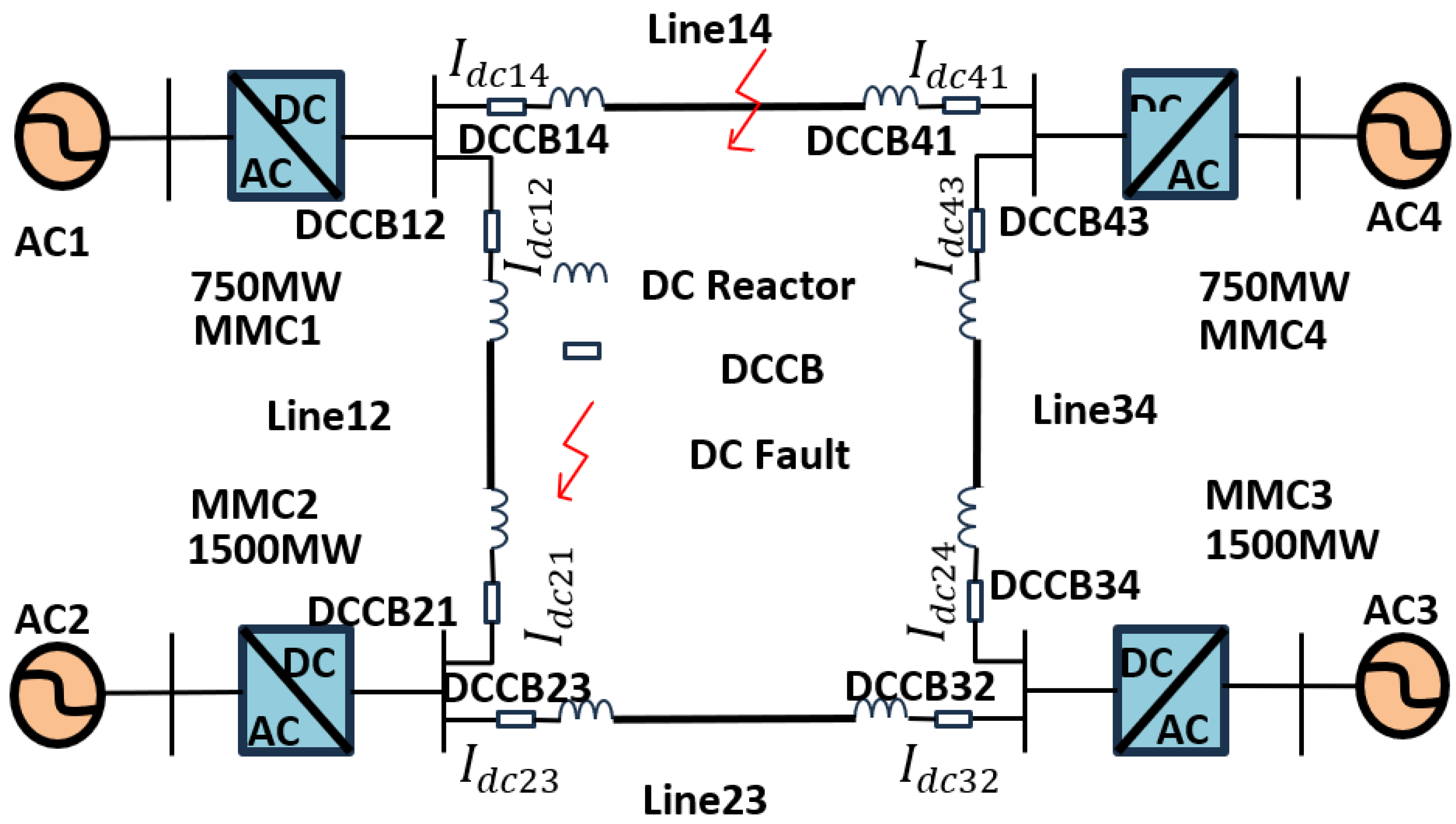
Figure 4.
Critical waveforms for fault parameters.

Table 1.
Parameters of the four-terminal DC grid.
| Converter Station | Number of Submodules | Submodule Capacitance/μF | Bridge Reactance/mH | Control Strategy |
|---|---|---|---|---|
| MMC1 | 250 | 7500 | 100 | P = −1500 MW Q = 0 MVar |
| MMC2 | 250 | 15,000 | 75 | P = 750 MW Q = 0 MVar |
| MMC3 | 250 | 15,000 | 75 | P = 1500 MW Q = 0 MVar |
| MMC4 | 250 | 7500 | 100 | Udc = 500 kV Q = 0 MVar |
Table 2.
Dual Terminal IGBT-MMC System Parameters.
| Parameters | Value | Parameters | Value |
|---|---|---|---|
| MMC Capacity/MW | 1800 | Transformer capacity/MVA | 1800 |
| Number of submodules | 250 | DC line reactance/H | 0.15 |
| DC voltage/kV | 500 | Transformer ratio/kV | 530/210 |
| Submodule capacity/mF | 7.5 | Bridge reactance/H | 0.1 |
Table 3.
Fault parameter.
| Parameters | Vector Control | Energy Fluctuation Control | Feed-Forward Control |
|---|---|---|---|
| Energy Dissipation/kJ | 11,901 | 6602.4 | 6493.2 |
| Peak Fault Current/kA | 10.226 | 7.820 | 7.630 |
| Voltage/kV | 648.90 | 741.10 | 753.40 |
Disclaimer/Publisher’s Note: The statements, opinions and data contained in all publications are solely those of the individual author(s) and contributor(s) and not of MDPI and/or the editor(s). MDPI and/or the editor(s) disclaim responsibility for any injury to people or property resulting from any ideas, methods, instructions or products referred to in the content. |
© 2024 by the authors. Licensee MDPI, Basel, Switzerland. This article is an open access article distributed under the terms and conditions of the Creative Commons Attribution (CC BY) license (https://creativecommons.org/licenses/by/4.0/).
Share and Cite
MDPI and ACS Style
Zhao, Z.; Jin, Q.; Wu, Y.; Li, G.; Xiang, T. Study of Energy Flow Mechanisms in High Power Device Converters. Energies 2024, 17, 1980. https://doi.org/10.3390/en17081980
AMA Style
Zhao Z, Jin Q, Wu Y, Li G, Xiang T. Study of Energy Flow Mechanisms in High Power Device Converters. Energies. 2024; 17(8):1980. https://doi.org/10.3390/en17081980
Chicago/Turabian StyleZhao, Zheyuan, Qianzheng Jin, Yingjie Wu, Gen Li, and Tiange Xiang. 2024. "Study of Energy Flow Mechanisms in High Power Device Converters" Energies 17, no. 8: 1980. https://doi.org/10.3390/en17081980
Note that from the first issue of 2016, this journal uses article numbers instead of page numbers. See further details here.