
Harnessing Geothermal Energy Potential from High-Level Nuclear Waste Repositories
by
 , ,
, ,
Dauren Sarsenbayev
1,*,
Liange Zheng
2,
Dinara Ermakova
3,
Rashid Sharipov
4 and
Haruko M. Wainwright
1,5,6 1
Department of Nuclear Science and Engineering, Massachusetts Institute of Technology, Cambridge, MA 02139, USA
2
Energy Geosciences Division, Lawrence Berkeley National Laboratory, Berkeley, CA 94720, USA
3
Department of Nuclear Engineering, University of California, Berkeley, CA 94720, USA
4
Department of Engineering and Information Technology, Kazakh-German University, Almaty 050010, Kazakhstan
5
Department of Civil and Environmental Engineering, Massachusetts Institute of Technology, Cambridge, MA 02139, USA
6
Earth and Environmental Sciences Area, Lawrence Berkeley National Laboratory, Berkeley, CA 94720, USA
*
Author to whom correspondence should be addressed.
Energies 2024, 17(9), 2002; https://doi.org/10.3390/en17092002
Submission received: 19 February 2024
/
Revised: 8 April 2024
/
Accepted: 17 April 2024
/
Published: 23 April 2024
(This article belongs to the Section H: Geo-Energy)
Abstract
:The disposal of high-level nuclear waste (HLW) has been one of the most challenging issues for nuclear energy utilization. In this study, we have explored the potential of extracting decay heat from HLW, taking advantage of recent advances in the technologies to utilize low-temperature geothermal resources for the co-generation of electricity and heat. Given that geothermal energy entails extracting heat from natural radioactivity within the Earth, we may consider that our approach is to augment it with an anthropogenic geothermal source. Our study—for the first time—introduces a conceptual model of a binary-cycle geothermal system powered by the heat produced by HLW. TOUGHREACT V3.32 software was used to model the heat transfer resulting from radioactive decay to the surrounding geological media. Our results demonstrate the feasibility of employing the organic Rankine cycle (ORC) to generate approximately 108 kWe per HLW canister 30 years after emplacement and a heat pump system to produce 81 kWth of high-potential heat per canister for HVAC purposes within the same timeframe. The proposed facility has the potential to produce carbon-free power while ensuring the safe disposal of radioactive waste and removing the bottleneck in the sustainable use of nuclear energy.
1. Introduction
Nuclear power generation produces high-level radioactive waste (HLW)—spent nuclear fuel and vitrified waste from reprocessing—that includes fission products and actinides [1]. Among the countries that use nuclear technology to generate electricity, there has been substantial progress in the safe management and disposal strategies of HLW, including the development of deep geological repositories [2]. To date, most research and development efforts for disposal have been focused on studying the evolution of the disposal site conditions and engineered barrier systems (EBS), such as premature canister corrosion and alterations in the physicochemical properties of clay formations [3,4].
One of the challenges of handling and storing HLW is decay heat [1], the heat released from radioactive decay. Decay heat decreases over time depending on the types and amount of radionuclides in the waste. The elevated temperature may alter the properties of the EBS by accelerating the corrosion of the waste canisters and the degradation of bentonite used as a backfill material and by affecting the hydrological and geochemical properties of host rocks [5,6]. Thus, the maximum allowable temperature is an important design variable for a geological repository because it determines the intermediate storage time, as well as the spacing of canister emplacements [1].
One unexplored option (to the authors’ knowledge) is to utilize HLW as a heat source during the first several decades of canister emplacement. A significant amount of heat released due to radioactive decay can be converted to electric power using binary cycle technology [7,8]. Geothermal energy is the energy obtained from the Earth’s internal heat, which is in fact generated by the radioactive decay of isotopes in Earth’s core, mantle, and crust [9]. The radioactive waste can be considered an anthropogenic geothermal source and suitable repository designs can be developed with built-in heat exchangers in proximity to the canisters. As the generated heat is continuously extracted by the heat exchangers, the thermal–hydrological–mechanical–chemical (THMC) properties of the formation containing the canister could be controlled and monitored for a considerable amount of time.
In the existing literature, Westinghouse proposed a design that utilizes decay heat from nuclear fuel stored in spent fuel pools (SFPs) to power emergency cooling systems based on thermoelectric modules and waste heat engines [10]. These systems were intended to convert decay heat into electricity and drive turbines with a vaporized working fluid. While Westinghouse’s innovation in utilizing SFP decay heat was patented, it has not been used in real-world applications. In addition, there have not been any research studies that have explored the utilization of decay heat in storage or disposal settings.
Geothermal energy for domestic use has been developing rapidly in recent years, providing stable carbon-free electricity and supplying heating, ventilation, and air conditioning (HVAC) systems [7]. Geothermal resources are classified (with reference to their temperature) as low, medium, and high-temperature resources. Traditionally, geothermal energy was only considered for high temperatures (exceeding 150 °C), since conventional electricity generation in a power plant requires water or steam at very high temperatures (150–550 °C) [11].
A particularly recent development relevant to this study is the viability of utilizing low-temperature geothermal resources for the co-generation of electricity and heat at temperatures below 149 °C [11]. This technology is achieved through a binary cycle of geothermal water and low-boiling working fluid in industrial-scale power plants. Binary cycles are thermodynamic cycles using two working fluids, one of which has a low saturation pressure at high temperatures and the other has a low vaporization temperature [8]. The higher-boiling working fluid, after the rotation of the turbine, gives off heat to the condenser, which is also the evaporator for the lower-boiling working fluid.
Building on these new opportunities, this study introduces a conceptual model of a binary cycle geothermal system powered by the heat produced by HLW within the geological repository. Unlike natural geothermal resources, whose availability is geographically constrained [12,13], the heat from HLW presents a more widespread opportunity to generate clean energy while addressing waste disposal challenges.
We will quantify (1) the electricity generation potential via the organic Rankine cycle and (2) the potential for producing heat for HVAC purposes via a heat pump unit. TOUGHREACT V3.32 software was employed in this work to model the heat production and transfer resulting from radioactive decay. In addition, we will evaluate the safety concerns of the proposed concept. We assume a typical repository setting across different countries, having the mined repository several hundred meters below the groundwater table. We explore different ways of harnessing thermal energy generated by HLW and converting it into practical forms of energy that can be utilized for geothermal heat pumps and electricity generation, employing a steam turbine within the organic Rankine cycle. To the authors’ knowledge, this is the first study to systematically explore the possible use of decay heat in the repository setting.
2. System Description
A representative illustration of a deep geological repository system with an intermediate energy system is represented in Figure 1, while Figure 2 shows a schematic diagram of an HLW disposal facility with a heat exchanger. In the deep geological repository, the multi-barrier system (including EBS and the natural barrier system) provides the isolation of waste from the biosphere. One of the elements of the EBS is a buffer material designed to seal radioactive waste packages within the underground storage facility [14,15]. Although we do not consider a particular site or repository, we assume the repository design parameters commonly used, which are stated in the subsequent sections.
The heat extraction system functions similarly to a geothermal heat pump. Initially, water is injected into the subsurface and circulates in the pipes around a canister, absorbing heat. This heated water is then pumped back to the surface. Upon reaching the surface, a heat exchange occurs within the evaporator of the heat pump system (HPS) or ORC loops through the primary vertical ground heat exchanger (VGHE) loop. This process facilitates the transfer of thermal energy to the refrigerant—R141b for the HPS and R142b for the ORC.
We assume that the heat extraction is strictly during the post-closure period immediately after the repository development with active monitoring to ensure safety. In addition, we assume that the pipes can be properly sealed and plugged after the operation is ceased for permanent disposal.
3. Materials and Methods
Our modeling framework consists of five stages from heat generation to energy harnessing: (1) heat generation; (2) heat transfer including flow and physical processes near the waste in the subsurface; (3) heat extraction through VGHE within the EBS; (4) counter-flow heat exchange between the VGHE and the evaporator, and (5) harnessing the extracted heat to generate useful energy within the thermodynamic cycles.
3.1. Heat Generation
After a reactor shutdown, fission reactions essentially cease but heat release continues, owing to the radioactive decay of the accumulated fission products and actinides [1]. The decay heat is dependent on the spent fuel’s radionuclide content. This, in turn, depends on the fuel’s burnup and the length of the interim storage time before deposition in the repository. The two fission products, 137Cs and 90Sr (with half-lives of about 30 years), are the isotopes that account for the majority of heat generation during the first few centuries [1].
We assumed the spent fuel from a typical PWR core, containing 157 fuel assemblies with a total thermal power of 3300 MWth [16]. The power history used for the calculations is approximated as 4 years of operation at full power [17], with a cooling time of 4 years [18]. We consider four assemblies per canister [19].
The American National Standard for Decay Heat Power [20] can be used to quantify the decay heat power as a function of time by a sum of 23 exponentials. Since for up to a few hundred years the 19th exponential decay group is dominant for up to a few hundred years, the decay heat output of the canister can be approximated as
where P0 is the initial rate of heat production, λ is the decay constant for group 19, and t is time.
P(t) = P0e−λt,
3.2. Thermal–Hydrological (TH) Model
In this study, we have modeled two relevant TH processes, namely (a) thermal conduction and (b) the bentonite hydrology saturation process. Thermal conduction is the main mechanism at work during the canister’s thermal evolution. The thermal and hydrodynamic parameters used in the model are listed in Table 1. We assume that the EBS buffer is composed of FEBEX bentonite and that the host-rock properties of argillite are adapted from the properties of Opalinus clay [21].
In the proposed repository, bentonite serves a dual purpose: (1) as a heat conductor (grout), aiding energy transfer, and (2) as an engineered barrier, retarding the radionuclide migration through the sorption to clay minerals. In addition, we assume that radiation sensors would be instrumented to monitor the radiation level within the circulating fluid.
For hydrology, the water intrusion into the buffer is explicitly modeled, using a two-phase flow model with vapor-pressure-lowering effects due to capillary pressure (approximated by the van Genuchten function). The thermal conductivity is a function of water saturation determined from the following linear relationship:
where Sl is the liquid saturation level and kdry and kwet are the thermal conductivities under dry and fully saturated conditions, respectively.
kth = kwet + Sl(kwet − kdry),
3.3. TH Model Implementation in Numerical Models
We use TOUGHREACT to compute the coupled TH processes in a generic bentonite-buffered nuclear waste repository, including an emplacement tunnel at a depth of 300–1000 m [22]. TOUGHREACT is a computer code that simulates the behavior of fluid flow and heat transport as well as geochemical reactions in geologic media [22]. The depth range was considered constant in our calculations and we did not vary the length of the emplacement tunnels when assessing heat losses. This approach was based on the assumption of negligible heat losses, through insulation of the pipes and grouting of the surrounding medium. Consequently, the heat transfer modeling primarily focuses on the canister–bentonite interface, positing that the heat exchanger is situated in the vicinity of the canister to optimize thermal energy capture. Furthermore, the energy transfer processes within the HPS and ORC were modeled independently of the tunnel length, considering the potential placement of these systems at various proximities to the canister. This methodological choice reflects our intent to illustrate the best-case scenario in terms of thermal energy recovery efficiency.
In this simplified domain, the canister is modeled as a heat source with steel’s mechanical properties. The mesh (Figure 3) used in the numerical simulation was taken from Cao et al. [21,23,24]; the applicability of this model is limited to the interpretation and prediction of the behavior of TH, primarily in the vicinity of the canister where thermal effects are significant. We adopted an axisymmetric mesh to represent the symmetrical heating process of the EBS. This meshing approach is grounded in the symmetrical nature of the thermal behavior observed in the EBS, which allows for a significant reduction in computational load [25]. The mesh used in our study has been previously validated and sensitivity analyses of THMC parameters were conducted in existing research [21,23,25].
A non-isothermal mode was used to simulate this model, describing the changing heat-power output over time. The bentonite undergoes re-saturation, heating, and chemical modification starting at time zero. As per the initial condition, there is no fluid flow at the canister surface and the liquid pressure is 7 bar at r = 50 m. The EBS initial temperature is uniform and equals 12 °C. Initially, bentonite has a water saturation of 59% and a suction of 1.11 × 10⁵ [kPa]. The host rock is fully saturated.
3.4. Heat Extraction Cycle Modeling
We used the SmoWeb software [26] to generate the pressure-enthalpy (P-h) diagrams of the organic Rankine cycle (ORC) and heat pump system (HPS) and also to determine the installation’s efficiency and power values. SmoWeb is a computing platform written in Python, which includes a number of applications built on its basis [26]. In this work, SmoWeb was used to determine the (1) heat exchange between the EBS and primary (VGHE) loop; (2) heat exchange between primary (VGHE) and secondary (HPS/ORC) loops; (3) heat pump installation’s coefficient of performance (COP); and (4) efficiency and turbine power output of the ORC.
3.4.1. Heat Exchange between the EBS and VGHE
Since most heat exchangers function in an environment where pressure variations are minimal, the constant pressure assumption is applicable to a wide range of real-world settings [27]. Thus, the determination of heat exchange between the EBS and the thermal fluid can be simplified by assuming constant pressure and equating the enthalpy change to the heat transfer. A steady-state one-dimensional plane wall model was employed to simulate heat transfer at the interface between the heat exchanger and the bentonite canister, given the assumption of uniform temperature distribution at this interface. This simplification was chosen to maintain focus on the critical heat exchange processes. The initial temperature, Ti, is considered uniform across the VGHE’s entire length, aligning with the steady-state assumption to examine long-term behavior rather than transient dynamics. While we acknowledge that a radial transient model might provide a more detailed representation, this assumption is sufficient for the current proof-of-concept study.
In the case of VGHE in the EBS, heat is absorbed; hence, the enthalpy change is positive (H > 0). To find the temperature increase in the thermal fluid, we use , where ΔTt.f. is the temperature increase in the thermal fluid [°C], Q is the heat transfer rate from the surroundings to the fluid [W], ṁ is the mass flow rate of the fluid [kg/s], and Cp is the specific heat capacity of the fluid [J/(kg × °C)].
To calculate the heat-transfer rate (Q), we use the one-dimensional conduction equation, assuming that the VGHE is located within the EBS, specifically 0.479 m radially away from the center of the canister, , where k is the thermal conductivity of the pipe material [W/(m×K)], A is the surface area of the pipe [m2], TEBS is the temperature of the EBS [°C], Ti is the initial temperature of the thermal fluid [°C], and d is the thickness of the pipe [m].
Finally, we substitute the calculated Q value to find the temperature increase in the thermal fluid, as follows: .
3.4.2. Heat Exchange between the VGHE and HPS/ORC
The thermal fluid’s raised temperature potential is now used as the source temperature of the heat pump/ORC. For both energy technologies, counter-flow heat exchange is considered at the corresponding evaporators. We use the NTU (number of transfer units) approach to simulate the heat sink with a counterflow configuration in the context of geothermal and refrigerant loops in ORC/HPS.
The heat-flow rate in a counter-flow heat exchanger can be determined by calculating the effectiveness of the heat exchanger, ε, which is a dimensionless value from 0 to 1. The NTU method relies on the heat capacity ratio (Cr) and the total number of transfer units such that ε = f(NTU, Cr), where , , Qmax is the maximal possible heat flow rate [W], U is the overall heat-transfer coefficient [W/(m2×K)], A is the heat-exchange area [m2], and Q1 and Q2 are the heat-transfer rates into thermal fluid and the refrigerant, respectively [W].
In the context of counter-current flow configuration, the effectiveness correlation is in the form
The NTU method defines the heat-transfer rate between two fluids in terms of an effectiveness parameter ε: Q1 = −Q2 = εc.f.Qmax = Qc.f., where Qmax = Cmin(T1in, T2in). Cmin = (ṁ1Cp,1, ṁ2Cp,2) and is the minimal value of the heat capacity rate. T1in and T2in are the intake temperatures of thermal fluid and refrigerant, respectively, while ṁ1 and ṁ2 are the mass flow rates of thermal fluid and refrigerant entering the heat exchanger, respectively. Qc.f. is the heat-transfer rate in the counter-flow heat exchanger [28].
Finally, the heat-transfer rate between the heating medium (thermal fluid) and the refrigerant in the HPS/ORC evaporator is used to determine the temperature rise of the refrigerant. The resulting higher temperature potential of the refrigerant, along with later defined assumptions, is then utilized in simulating the heat pump cycle and the ORC in the following subsections.
3.4.3. Vapor Compression Heat Pump Cycle
A geothermal heat pump is a heating/cooling system for buildings that transfers heat to or from the ground. The efficiency of a heat pump is measured by a coefficient of performance (COP), which is typically in the range of 2 to 6. This means that for every unit of electricity used, the devices produce 2 to 6 units of heat [29].
In this work, we consider a heat pump with VGHE, designed as U-shaped stainless-steel pipes. The considered VGHE are placed in vertical wells, with the space between the pipes filled with bentonite grout. Water is utilized as the working fluid in the primary loop and R141b refrigerant is employed in the secondary loop. The system works as follows. The heat supplied to the vertical ground heat exchanger is transferred by the intermediate heat carrier in the evaporator to the boiling refrigerant. After leaving the evaporator, the superheated refrigerant enters the compressor, where it is compressed to a pressure corresponding to the required saturation temperature in the condenser. The superheated refrigerant vapor then enters the condenser, where it is cooled and condensed. The coolant transfers the heat from the condenser to the consumer. After leaving the condenser, the refrigerant enters the expansion valve and the liquid refrigerant expands to the pressure in the evaporator [29,30]. Since no work is conducted in the heat pump evaporator, the enthalpy change is equal to the heat added to the fluid. It is assumed that the refrigerant is completely condensed in the condenser. Figure 4 illustrates a ground source HPS incorporating the utilization of heat from spent nuclear fuel (SNF)/HLW.
The following equations are employed in the modeling of heat and work transfer in the heat pump. Fluid is compressed adiabatically by an isentropic compressor. In this model, the entropy of the outflow state of an ideal isentropic heat exchanger is equal to that of the input state such that Wid = h(p2, s1) − h(p1, s1), where Wid represents the ideal work, measured in watts [W], h denotes the enthalpy at the compressor [J], p2 is the pressure at the inlet of the system [Pa], p1 is the pressure at the outlet of the system [Pa], and s1 is the entropy of the outflow state of an ideal isentropic heat exchanger [J/K].
The real work (Wr) is found as the ratio of ideal work (Wid) to the compressor’s isentropic efficiency (η), as follows:
Work that is dissipated as heat in the environment (Qout) is defined by fQ: Qout = WrfQ.
Finally, the specific enthalpy, which is derived by the energy balance, and outlet pressure are used to calculate the outlet state of the compressor: hout = hin + Wr − Qout.
In this model, the throttle valve expansion is isenthalpic (adiabatic, producing no work). In both the evaporator and condenser, the pressure drop is neglected. Since no work is performed, the enthalpy change is equal to the heat added to the fluid.
For heating, COP is calculated as the ratio of the heat output of the heat pump to the power consumed by the compressor, as follows:
where is the energy given off by the HPS [W] and is the electrical energy consumed by the compressor [W].
3.4.4. Organic Rankine Cycle
We use ORC for electricity generation, employing a refrigerant with a low boiling point instead of water as the working fluid. This approach enhances heat transfer efficiency from the canister zone. The system is designed with two loops: water serves as the working medium in the primary loop, while the secondary loop operates with R142b refrigerant. R142b has been chosen for its optimal physicochemical properties and its prevalence in contemporary vapor-compression technology [32]. Water is an appropriate thermal fluid for the primary loop due to its high critical temperature [33]. Figure 5 illustrates the components of a typical ORC system.
Our analysis involves applying the fundamental principles of conservation of energy, derived from the first law of thermodynamics, to the evaporator, condenser, turbine, and pump [34]. The general form of the first law of thermodynamics, applicable to systems with a steady flow, is expressed as follows:
where is the heat added to the system [J], Ẇ is the work performed by the system [J], ṁ2 is the mass flow rate of the fluid at the outlet [kg/s], ṁ1 is the mass flow rate of the fluid at the inlet [kg/s], h2 is the specific enthalpy at the final state [J/kg], h1 is the specific enthalpy at the initial state [J/kg], v2 is the speed of fluid at the final state [m/s], v1 is the speed of fluid at the initial state [m/s], z2 is the vertical height at the outlet [m], z1 is the vertical height at the inlet [m], and g is the acceleration due to gravity [m/s2].
In this model, we consider a single flow; therefore, Equation (6) can be rewritten as
where ṁ is the mass flow rate of the fluid [kg/s].
In conducting an energy analysis of the ORC’s main components, the subscripts 1 and 2 indicate fluid conditions at the inlet and outlet, respectively. Equation (7) is considered to be an appropriate form of the first law of thermodynamics for this purpose, regardless of the layout of the ORC design.
The energy extraction by the working fluid in the evaporator = ṁ(h3 − h2). This equation assumes that any hydrodynamic effects resulting from changes in velocity and level are not significant. In addition, it is assumed that the evaporator is not doing any work and therefore this term is assumed to be zero. The process in the evaporator is assumed to be isothermal in the area of heat transfer to the working fluid at constant pressure. Heat loss to the environment is also considered zero due to the ideal insulation of the heat exchanger. Finally, it is assumed that the pressure drop experienced by the working fluid is negligible due to its small magnitude.
The following are formulas used for calculating the energy values of the turbine. We assume an insignificant difference in heights between the inlet and outlet; therefore,
The condenser analysis is based on the same assumptions as for the evaporator. Thus, the condenser load calculation follows the same approach as for the evaporator and can be expressed as follows: = ṁ(h4 − h1).
The pump in the ORC performs an isentropic process, the function of which is to move the working fluid from low-pressure areas to high-pressure areas in the cycle. Using Equation (7) results in
where is the work performed by the pump, is the isentropic efficiency of the pump, and is the (ideal) isentropic specific enthalpy at the pump’s outlet.
The thermal efficiency for the ORC is calculated from the energy supplied to the evaporator and the net output of the cycle. Thermal efficiency is derived by determining the ratio of the ORC net output to the energy supplied to the evaporator. The following equation is the first law of thermodynamics for ORC, which relates the input and output energy of a cycle:
The power output of an ORC (Ẇ) is equal to the difference between the power generated by the turbine and the power consumed by the pump driving the cycle: Ẇ = Ẇturb − Ẇpump. In other words, net power output is the amount of useful energy produced by the ORC after subtracting the energy needed to run the cycle.
The parameters for the ORC are presented in Table 4.
4. Results
4.1. Heat Transfer
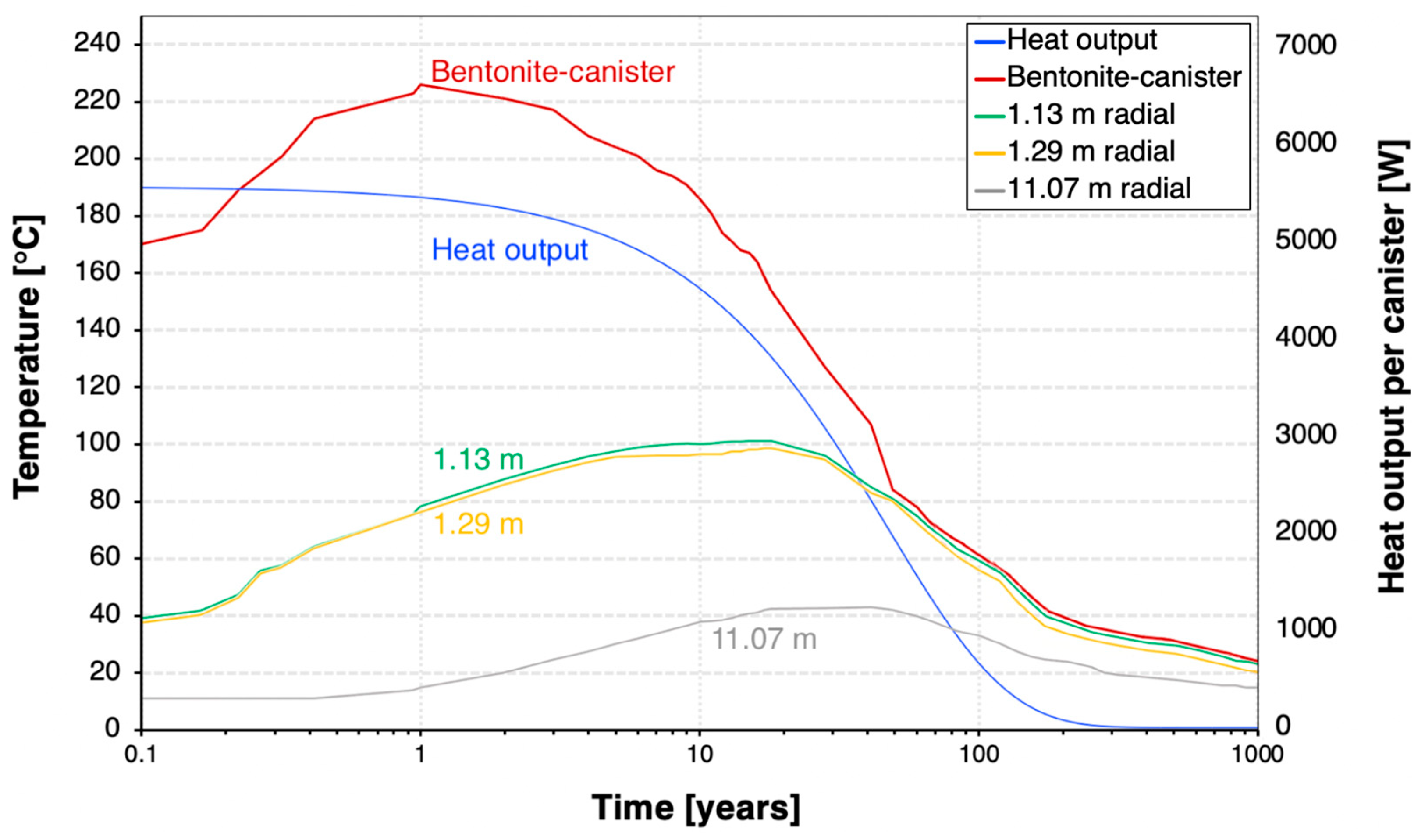
With the assumed 4-year cooling time, the decay heat decreases by 19% in 10 years and 90% in 100 years after the canister emplacement (Figure 6). The decay heat power is 5521 W per canister at the time of the discharge and then decreases to 2758 W after 30 years. The decay heat reduces to less than 1% of its initial value 300 years after canister emplacement.
Figure 6 also represents the temperature at various spatial points radially away from the canister. For the bentonite–canister interface, the temperature trend initiates at approximately 170 °C due to the logarithmic nature of the time scale, with the horizontal x-axis (time) starting at 0.1 year. The temperature at the bentonite–canister interface reaches a maximum value of 226 °C at 1 year after canister emplacement. It stays above 120 °C for 30 years, which is the estimated lifespan of an ORC. In 100 years, the temperature will drop to approximately 50 °C and eventually decline to less than 20 °C 1000 years after the discharge.
Moreover, we assess the thermal response of the host rock. In contrast to the canister–bentonite thermal response, the bentonite–host rock interface (1.13–1.29 m radially away from the canister) experiences a longer thermal evolution, reaching a peak of around 100 °C after 20 years. The host rock reaches its maximum temperature of 42 °C four decades following the installation of the heater, underscoring the host rock’s low thermal conductivity in dissipating heat.
Initially, at year one, the temperature gradient is most pronounced at the bentonite–canister interface, where the heat flux generated by radioactive decay is greatest. Over time, this heat dissipates through the bentonite, leading to temperature equalization of the EBS. Concurrently, as the radioactive material in SNF/HLW decays to a stable form, the intensity of decay heat decreases. After 50 years, the bentonite buffer achieves a near-uniform temperature distribution, with each spatial point approximately reaching 80 °C, followed by a gradual and consistent temperature decline across the buffer. This observation of uniform temperature distribution in bentonite provides further details of the decay heat dissipation kinetics within the repository. The predominant heat release is observed in the initial 50 years, after which the thermal gradient begins to stabilize.
4.2. Vapor Compression Heat Pump Cycle
In the P-h diagram (Figure 7), the area of the enclosed graph increases over the period of 30 years, indicating an increase in the useful heat output by the condenser. The COP is above 2 for the first 10 years and reaches 1.5 at the 30-year temporal point. For convenience, the values in the P-h diagram are presented in Table 5; the listed energy parameters were calculated using the acquired enthalpy values and the assumptions mentioned in Section 3.4.3.
After one year, the heat pump’s condenser showed a COP of 5.6 and a thermal energy production of around 70 kW/canister. The HPS showed an increased useable heat production of 73 kW/canister after 10 years of operation and the capacity to produce 80 kW of thermal energy per canister after three decades. The heat pump yielded greater thermal heat (QH) compared to the energy input supplied to the compressor, thereby illustrating its sustained effectiveness over a 30-year operational span.
Our choice to concentrate on the specified recession periods stems from their relevance to the lifespans of ORC and HPS systems, which are generally observed to be under 15–30 years [36,37]. Hence, 1 year, 10 years, and 30 years are intentionally aligned with the most critical periods for evaluating the performance of the HPS and ORC.
4.3. Organic Rankine Cycle
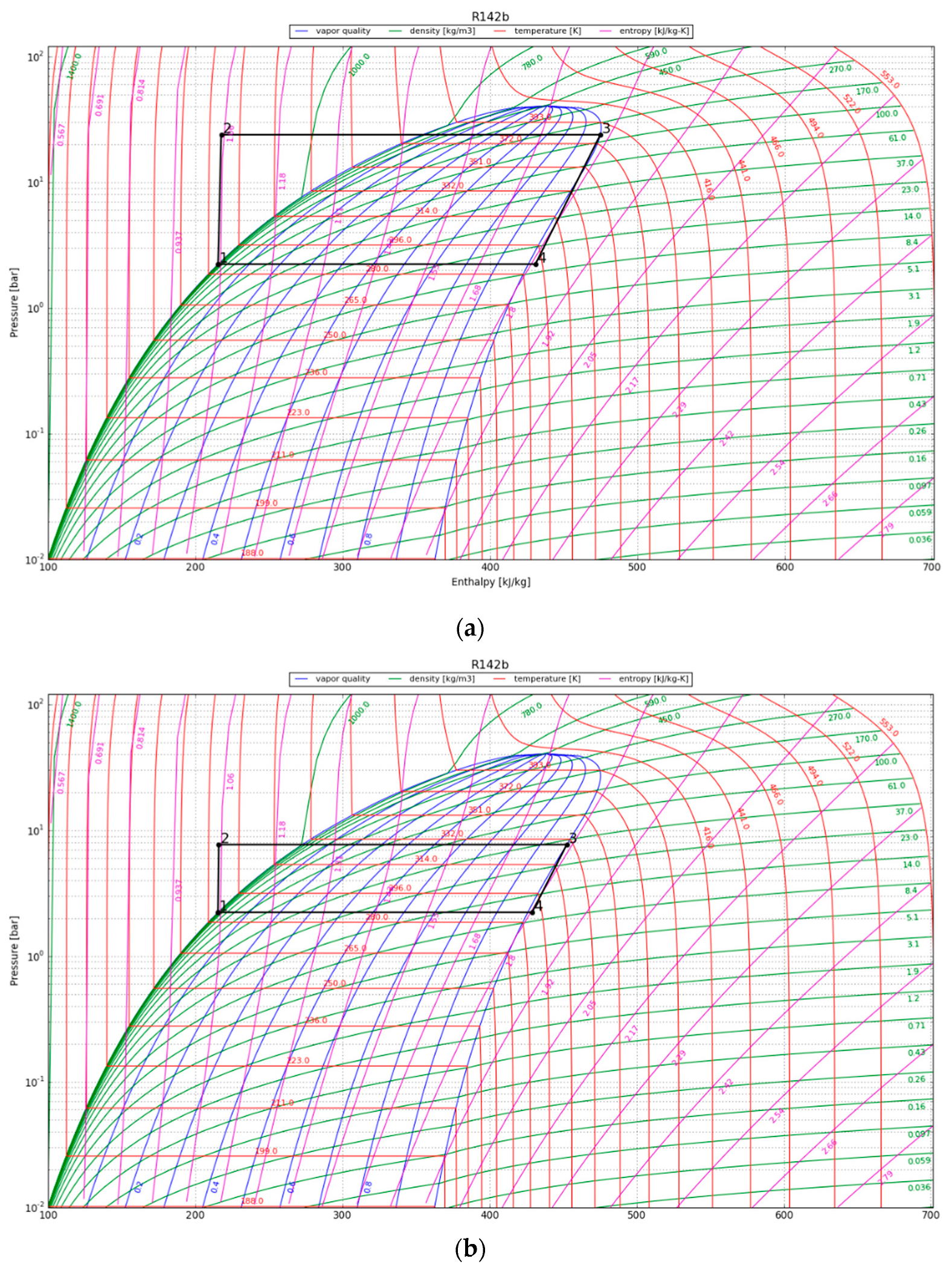
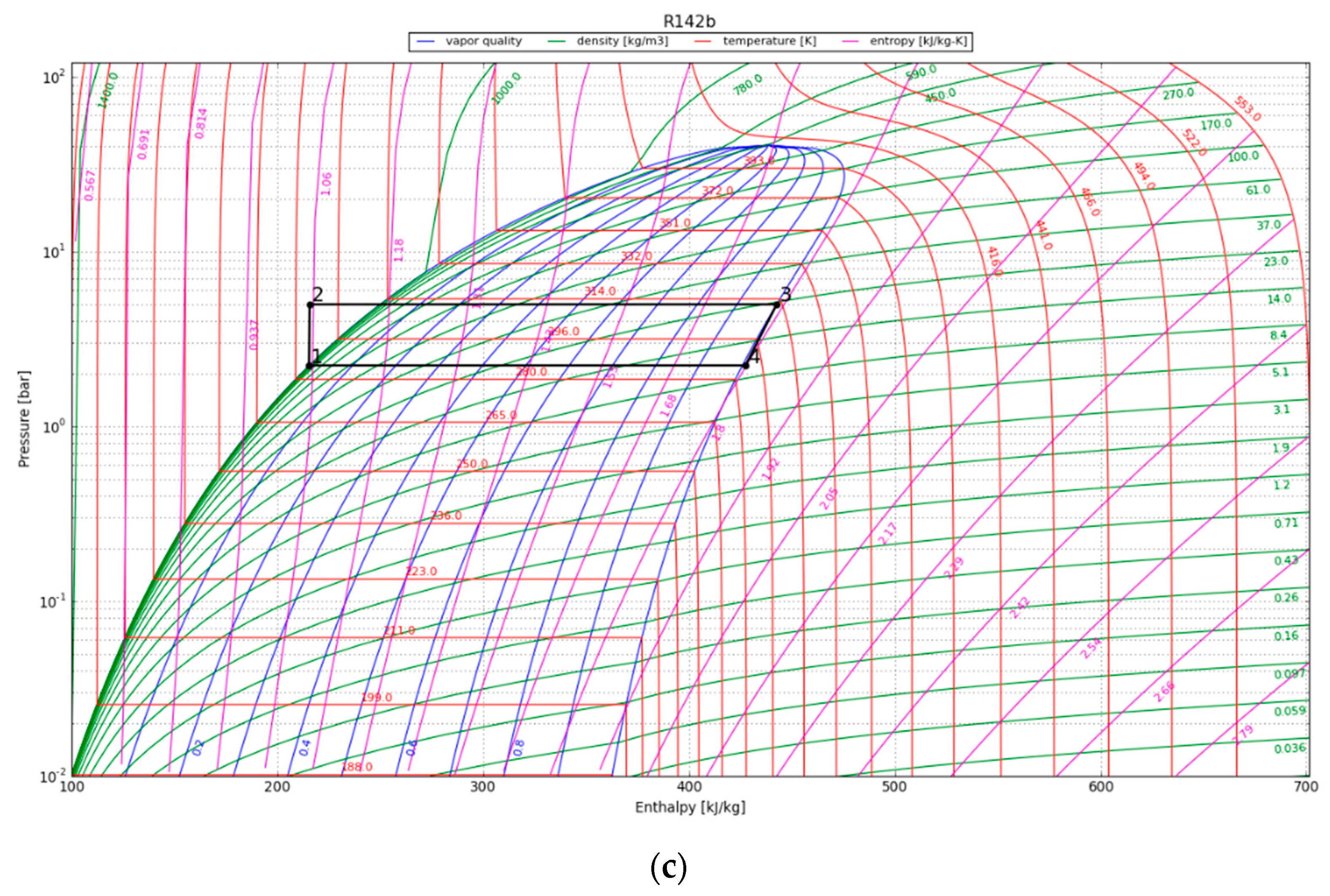
The P-h diagrams of the modeled ORC systems are depicted in Figure 8. Two points, 3 and 4, have a major impact on the power output by the system. Notably, point 4 marked the starting point of condensation for the working fluid. The region encircling the cycle on the P-h diagram illustrates the net work output of the ORC. The net work output and, thus, the cycle efficiency increase with the size of the cycle’s enclosing area. We observe that the efficiency of the ORC is highly dependent on the initial refrigerant parameters, especially the superheated vapor temperature at constant pressure, as it increases the thermal efficiency of the cycle by increasing the average thermal input temperature. The P-h diagram was used to calculate the amount of work that could be recovered from the cycle, provided the expander operated adiabatically. The obtained output results are listed in Table 6.
The maximum cycle efficiency for the considered ORC was found to be 16.4%. This efficiency is realized approximately one year after system initialization when the refrigerant temperature reaches 107 °C. Thus, assuming a generator efficiency of 95%, the maximum expected power generation of the ORC would be approximately 294 kWe/canister. The estimated electricity generation would be around 102 kWe/canister after 30 years. To contextualize the electricity generation estimate, on average, a typical household consumes about 10,715 kWh of electricity annually [38]. This equates to around 890 kWh per month or roughly 29 kWh per day, providing a benchmark for residential energy needs. In order to evaluate the possible impact of the ORC turbine, we can examine a scenario in which the system runs continuously. Under this condition, the ORC system can provide enough power to sustain approximately 80 single-family houses for a minimum of three decades.
5. Discussion
We have shown that spent fuel can be a viable geothermal energy resource, even though the source temperature is less than the conventional geothermal threshold. Holdmann (2007) illustrated the feasibility of an ORC system, driven by a geothermal fluid temperature of 74 °C at the Chena Hot Springs Resort in Alaska, United States. The reported power plant consists of two 200 kW modules, engineered via commercially accessible technology [39].
The expansion of geothermal power plant development is geographically limited to areas situated in proximity to plate boundaries, mantle plumes, hot spots, or other sources of substantial heat flow [40]. Several nations have the capacity for large-scale geothermal energy utilization, namely Indonesia, the Philippines, Japan, New Zealand, and the United States [41]. However, in the context of harnessing anthropogenic geothermal energy from HLW repositories, the projected energy recovery potential presents an opportunity to produce power comparable to the output of conventional geothermal power plants, irrespective of naturally occurring heat sources.
The efficiency values obtained (7–16%) fall within a range that has previously been shown to be economically viable, particularly for recovering waste heat from geothermal sources above 80 °C [42]. The key advantage within this temperature range lies in the heat source circuit’s capability to utilize water without the necessity for thermal oil, which is estimated to account for 11% of the total ORC investments [43]. Moreover, the proposed system uses a direct heat transfer from the primary to the secondary loop via an evaporator, increasing the efficiency of the system. It has been reported that this method leads to a reduction in ORC system costs by up to 15% [44]. Notably, while economic feasibility aspects were discussed, a formal economic feasibility study would be necessary in the future.
For the decay heat recovery, the ORC system is preferable since the use of heat pumps becomes impractical when the operating temperature reaches its limit. Comparing the ORC and the heat pump from an economic point of view, the ORC is more favorable due to higher efficiency ratios and lifespan compared to geothermal heat pumps. It should also be noted that there is potential for enhanced heat pump efficiency when considering points further in time and radial distance from canister placement.
We acknowledge that we did not consider the feedback from the energy extraction system to the TH model. Instead, we used the NTU approach to model the heat sink. This approach took into account the cooling of the heating medium and the temperature reduction in the working fluids (water and the refrigerants), following the heat exchange process. In addition, we would note that the actual temperature profile at the bentonite–canister interface could be more variable and affected by different conditions. We also acknowledge our study is a proof-of-the-concept study based on model simulations. In future research, experimental investigation will be required to enhance the practical applicability of these technologies. In addition, we acknowledge the limitation of excluding the potential heat losses along the emplacement tunnels. We assumed the ideal insulation of the pipes in addition to the grouting of the VGHE. Conducting a thorough assessment of heat losses from VGHE would be necessary in addressing this limitation in future studies.
We are also aware that there could be safety concerns. First, the high-temperature impact on bentonite needs to be considered. Several recent laboratory hydrothermal studies have been carried out to investigate the geochemical changes in bentonite and its interaction with clay rocks, granite, and concrete at temperatures reaching 200 °C. According to Cheshire et al., (2014; 2018), both studies revealed no significant changes in the properties of bentonite that could affect its safety-relevant properties [45,46]. Moreover, numerical simulations performed by Zheng et al. [47] and Chang et al. [48] suggest that FEBEX bentonite can withstand temperatures of up to 200 °C without compromising the functionality of the buffer. Second, the installation of VGHE might jeopardize the integrity of EBS and the corrosion of pipes might bring unknown geochemical changes in bentonite. However, cooling by removing heat from EBS has a positive impact on the integrity of EBS, which may outweigh the cons brought by the VGHE system.
Lastly, should an early failure of the canister occur, and radionuclides are released during the operation of VGHE, the pipes from the subsurface to the ground could be considered conduits for contaminants. As we mentioned above, we assume that this system is in conjunction with proper monitoring. In addition, decommissioning can be performed safely such that the pipes are plugged by low-permeability material. Since the energy conversion system near the surface is not in contact with the radioactive material, it can be disposed of as regular waste. At the same time, this system could be considered a monitoring system for the repository since temperature is often used for detecting changes in groundwater flow and groundwater systems, using distributed temperature sensors (DTS) [49]. The incident at the Waste Isolation Pilot Plant (WIPP) in 2014 has shown that there could be some unknowns that could trigger accidents during the repository operation or shortly after the closure [50]. We argue that having some access to the repository would enhance the safety of the repository, at the same time as extracting heat and economic values. There is a wealth of information about well leakage, wellbore integrity and closure, assessments, and detections from CO2 storage research [51].
6. Conclusions
This work introduces a proof-of-concept study using a numerical model of a binary-cycle geothermal system powered by the decay heat produced by HLW. TOUGHREACT V3.32 software was employed in this work to model the heat transfer from the waste form to the EBS. Our results indicate that the ORC can generate electricity within the binary-cycle geothermal system, while a heat pump system can produce high-potential heat for HVAC purposes. The study reports a maximum cycle efficiency of 16.4% for electricity generation and a COP of 5.6 for the heat pump system. The results indicate that ORC will yield approximately 108 kWe per canister 30 years after the canister emplacement, whereas the HPS is projected to produce 81 kWth per canister within the same timeframe. The proposed facility has the potential to generate high potential heat or produce carbon-free power from the heat otherwise dissipated as waste while ensuring the safe disposal of HLW.
Author Contributions
Conceptualization, H.M.W., D.S. and R.S.; methodology, H.M.W. and D.S.; software, D.S., H.M.W., L.Z. and D.E.; validation, D.S. and H.M.W.; formal analysis, D.S. and H.M.W.; investigation, D.S. and H.M.W.; resources, H.M.W., D.S. and L.Z.; data curation, D.S.; writing—original draft preparation, D.S. and H.M.W.; writing—review and editing, D.S., H.M.W., L.Z., D.E. and R.S.; visualization, D.S.; supervision, H.M.W., L.Z., D.E. and R.S.; project administration, H.M.W.; funding acquisition, D.S. and H.M.W. All authors have read and agreed to the published version of the manuscript.
Funding
This research was funded by a grant from the Shakhmardan Yessenov Science and Education Foundation, as part of the Research Internships in World Laboratories program, and by an internal grant from the Massachusetts Institute of Technology.
Data Availability Statement
The original contributions presented in the study are included in the article, further inquiries can be directed to the corresponding author.
Conflicts of Interest
The authors declare no conflicts of interest.
References
- International Atomic Energy Agency. Status and Trends in Spent Fuel and Radioactive Waste Management; IAEA Nuclear Energy Series NW-T-1.14 (Rev. 1); International Atomic Energy Agency: Vienna, Austria, 2022. [Google Scholar]
- Zheng, L.; Xu, H.; Rutqvist, J.; Birkholzer, J. Predicting the long-term evolution of bentonite buffer based on THMC models calibrated against the FEBEX in situ heater test. In AGU Fall Meeting Abstracts; American Geophysical Union: Washington, DC, USA, 2022. [Google Scholar]
- Johnson, L.; King, F. The effect of the evolution of environmental conditions on the corrosion evolutionary path in a repository for spent fuel and high-level waste in Opalinus clay. Nucl. Mater. 2008, 379, 9–15. [Google Scholar] [CrossRef]
- Hornus, E.C.; Giordano, C.M.; Rodriguez, M.A.; Carranza, R.M. Effect of temperature on the crevice corrosion resistance of Ni-Cr-Mo alloys as engineered barriers in nuclear waste repositories. In Proceedings of the XXXVIII Annual meeting of the Argentine Association of Nuclear Technology, Buenos Aires, Argentina, 14–18 November 2011; Volume 38, pp. 1–8. [Google Scholar]
- Kamei, G.; Mitsui, M.S.; Futakuchi, K.; Hashimoto, S.; Sakuramoto, Y. Kinetics of long-term illitization of montmorillonite—A natural analogue of thermal alteration of bentonite in the radioactive waste disposal system. Phys. Chem. 2005, 66, 612–614. [Google Scholar] [CrossRef]
- Horseman, S.T.; McEwen, T.J. Thermal constraints on disposal of heat-emitting waste in argillaceous rocks. Eng. Geo. 1996, 41, 5–16. [Google Scholar] [CrossRef]
- Nandhini, R.; Sivaprakash, B.; Rajamohan, N. Waste heat recovery from heat pumps, power cycles and integrated systems at low temperature. Review on system performance and environmental perspectives. Sustain. Energy Technol. Assess. 2022, 52, 102214. [Google Scholar] [CrossRef]
- DiPippo, R. Geothermal power plants: Evolution and performance assessments. Geothermics 2015, 53, 291–307. [Google Scholar] [CrossRef]
- Barbier, E. Geothermal Energy Technology and Current Status: An Overview. Renew. Sustain. Energy Rev. 2002, 6, 3–65. [Google Scholar] [CrossRef]
- Tatli, E.; Belechak, J.G.; Lu, B.; Stansbury, C.A.; Guler, C.; Ostrosky, M.J. Power Generation from Decay Heat for Spent Nuclear Fuel Pool Cooling and Monitoring. WO Patent WO2013019589, 7 February 2013. [Google Scholar]
- DiPippo, R. Geothermal Power Plants: Principles, Applications, Case Studies and Environmental Impact; Butterworth-Heinemann: Oxford, UK, 2012. [Google Scholar]
- Anderson, A.; Rezaie, B. Geothermal technology: Trends and potential role in a sustainable future. Appl. Energy 2019, 248, 18–34. [Google Scholar] [CrossRef]
- Limberger, J.; Boxem, T.; Pluymaekers, M.; Bruhn, D.; Manzella, A.; Calcagno, P.; Beekman, F.; Cloetingh, S.; van Wees, J.D. Geothermal energy in deep aquifers: A global assessment of the resource base for direct heat utilization. Renew. Sustain. Energy Rev. 2018, 82, 961–975. [Google Scholar] [CrossRef]
- Birgersson, M.; Hedström, M.; Karnland, O.; Sjöland, A. Bentonite buffer: Macroscopic performance from nanoscale properties. In Geological Repository Systems for Safe Disposal of Spent Nuclear Fuels and Radioactive Waste, 2nd ed.; Woodhead Publishing: Sawston, UK, 2017; pp. 319–364. [Google Scholar]
- Sellin, P.; Leupin, O.X. The use of clay as an engineered barrier in radioactive–waste management. Clay Clay Miner. 2013, 61, 477–498. [Google Scholar] [CrossRef]
- Breeze, P. Nuclear Power. Power Generation Technologies, 2nd ed.; Elsevier Science: Newnes, Australia, 2014; pp. 353–378. [Google Scholar]
- Pramuditya, S.; Takahashi, M. Core design study for power uprating of integral primary system PWR. Ann. Nucl. Energy 2013, 59, 16–24. [Google Scholar] [CrossRef]
- Favalli, A.; Vo, D.; Grogan, B.; Jansson, P.; Liljenfeldt, H.; Mozin, V.; Schwalbach, P.; Sjöland, A.; Tobin, S.J.; Trellue, H.; et al. Determining initial enrichment, burnup, and cooling time of pressurized-water-reactor spent fuel assemblies by analyzing passive gamma spectra measured at the Clab interim-fuel storage facility in Sweden. Nucl. Instrum. Methods Phys. Res. Sect. A 2016, 820, 102–111. [Google Scholar] [CrossRef]
- Fukaya, Y.; Nishihara, T. Reduction on high level radioactive waste volume and geological repository footprint with high burn-up and high thermal efficiency of HTGR. Nucl. Eng. Des. 2016, 307, 188–196. [Google Scholar] [CrossRef]
- ANSI/ANS-5.1; Decay Heat Power in Light Water Reactors. American National Standards Institute: Washington, DC, USA, 1979.
- Cao, X.; Zheng, L.; Hou, D.; Hu, L. On the Long-Term Migration of Uranyl in Bentonite Barrier for High-Level Radioactive Waste Repositories: The Effect of Different Host Rocks. Chem. Geol. 2019, 525, 46–57. [Google Scholar] [CrossRef]
- Xu, T.F.; Spycher, N.; Sonnenthal, E.; Zhang, G.; Zheng, L.; Pruess, K. TOUGHREACT Version 2.0: A simulator for subsurface reactive transport under non-isothermal multiphase flow conditions. Comput. Geosci. 2011, 37, 763–774. [Google Scholar] [CrossRef]
- Ermakova, D.; Wainwright, H.; Zheng, L.; Shirley, I.; Lu, H. Global Sensitivity Analysis for U(VI) Transport for Integrating Coupled Thermal–Hydrological–Chemical Processes Models Into Performance Assessment Model. ASME J. Nucl. Rad. Sci. 2021, 7, 041902. [Google Scholar] [CrossRef]
- Lu, H.; Ermakova, D.; Wainwright, H.; Zheng, L.; Tartakovsky, D. Data-Informed Emulators for Multi-Physics Simulations. J. Mach. Learn. Model. Comput. 2021, 2, 33–54. [Google Scholar] [CrossRef]
- Zheng, L.; Lammers, L.N.; Fox, P.M.; Chang, C.; Xu, H.; Borglin, S.; Whittaker, M.L.; Chou, C.; Tournassat, C.; Subramanian, N.; et al. Engineered Barrier System Research Activities at LBNL: FY20 Progress Report; Report #: LBNL-2001331; Lawrence Berkeley National Lab. (LBNL): Berkeley, CA, USA, 2020. [Google Scholar]
- SmoWeb. SysMo, Ltd. Bulgaria. Available online: http://platform.sysmoltd.com (accessed on 2 May 2023).
- Gut, J.A.W.; Pinto, J.M. Modeling of plate heat exchangers with generalized configurations. Int. J. Heat Mass Transf. 2003, 46, 2571–2585. [Google Scholar] [CrossRef]
- Bejan, A. Second-Law Analysis in Heat Transfer and Thermal Design. Adv. Heat Transf. 1982, 15, 1–58. [Google Scholar]
- Jordan, C.; Belding, S.; Campos, G.; Lowder, T. High Temperature Heat Pump Model Documentation and Case Studies; NREL/TP-7A40-84560; National Renewable Energy Laboratory: Golden, CO, USA, 2023. [Google Scholar]
- Chen, Y.; Lundqvist, P.; Johansson, A.; Platell, P. A comparative study of the carbon dioxide transcritical power cycle compared with an organic Rankine cycle with R123 as working fluid in waste heat recovery. Appl. Therm. Eng. 2006, 26, 2142–2147. [Google Scholar] [CrossRef]
- Lindeman, L. Thermodynamic Analysis of a High Temperature Heat Pump Coupled with an Organic Rankine Cycle for Energy Storage; Universitat Politècnica de València: Valencia, Spain, 2018; Available online: http://hdl.handle.net/10251/108965 (accessed on 27 March 2024).
- Badr, O.; Probert, S.D.; O’Callaghan, P.W. Selecting a working fluid for a Rankine-cycle engine. Appl. Energy 1985, 21, 1–42. [Google Scholar] [CrossRef]
- Mallamace, F.; Corsaro, C.; Mallamace, D.; Fazio, E.; Chen, S.H.; Cupane, A. Specific Heat and Transport Functions of Water. Int. J. Mol. Sci. 2020, 21, 622. [Google Scholar] [CrossRef] [PubMed]
- Tarrad Ali, H. What Every Engineer Should Know about the Organic Rankine Cycle and Waste Energy Recovery; Cambridge Scholars Publishing: Cambridge, UK, 2022. [Google Scholar]
- Wang, D.; Ling, X.; Peng, H.; Liu, L.; Tao, L. Efficiency and optimal performance evaluation of organic Rankine cycle for low grade waste heat power generation. Energy 2013, 50, 343–352. [Google Scholar] [CrossRef]
- Uusitalo, A.; Uusitalo, V.; Grönman, A.; Luoranen, M.; Jaatinen-Värri, A. Greenhouse gas reduction potential by producing electricity from biogas engine waste heat using organic Rankine cycle. J. Clean. Prod. 2016, 127, 399–405. [Google Scholar] [CrossRef]
- Ahmadi, A.; El Haj Assad, M.; Jamali, D.H.; Kumar, R.; Li, Z.X.; Salameh, T.; Al-Shabi, M.; Ehyaei, M.A. Applications of geothermal organic Rankine Cycle for electricity production. J. Clean. Prod. 2020, 274, 122950. [Google Scholar] [CrossRef]
- Shao, P. Eco-Friendly Hydro-Power: Turbulent. In Proceedings of the 6th International Conference on Economic Management and Green Development, Online, 6–12 August 2022; Springer Nature: Singapore, 2023. [Google Scholar]
- Holdmann, G. The Chena Hot Springs 400kW Geothermal Power Plant: Experience Gained During the First Year of Operation. Trans. Geotherm. Resour. Counc. 2008, 31, 515–519. [Google Scholar]
- Bassam, N.; Maegaard, P.; Schlichting, M.L. Distributed Renewable Energies for Off-Grid Communities; Elsevier: Amsterdam, The Netherlands, 2013. [Google Scholar] [CrossRef]
- International Energy Agency (IEA). Energy Technology Perspectives; International Energy Agency (IEA): Vienna, Austria, 2008. [Google Scholar]
- Quoilin, S.; Van Den Broek, M.; Declaye, S.; Dewallef, P.; Lemort, V. Techno-economic survey of Organic Rankine Cycle (ORC) systems. Renew. Sustain. Energy Rev. 2013, 22, 168–186. [Google Scholar] [CrossRef]
- Lemmens, S. Cost Engineering Techniques & Their Applicability for Cost Estimation of Organic Rankine Cycle Systems. Energies 2016, 9, 485. [Google Scholar] [CrossRef]
- U.S. Department of Energy. Modifications and Optimization of the Organic Rankine Cycle. Improving Recovery of Waste Heat in Industrial Processes. 2017. Available online: www.osti.gov/scitech (accessed on 27 March 2024).
- Cheshire, M.C.; Caporuscio, F.A.; Rearick, M.S.; Jové-Colón, C.; McCarney, M.K. Bentonite Evolution at Elevated Pressures and Temperatures: An Experimental Study for Generic Nuclear Repository Designs. Am. Mineral. 2014, 99, 1662–1675. [Google Scholar] [CrossRef]
- Cheshire, M.; Caporuscio, F.; Jove Colón, C.; Norskog, K.E. Fe-Saponite Growth on Low-Carbon and Stainless Steel in Hydrothermal-Bentonite Experiments. J. Nucl. Mater. 2018, 511, 353–366. [Google Scholar] [CrossRef]
- Zheng, L.; Rutqvist, J.; Xu, H.; Birkholzer, J. Coupled THMC models for bentonite in an argillite repository for nuclear waste: Illitization and its effect on swelling stress under high temperature. Eng. Geol. 2017, 230, 118–129. [Google Scholar] [CrossRef]
- Chang, C.; Borglin, S.; Chou, C.; Zheng, L.; Wu, Y.; Kneafsey, T.; Nakagawa, S.; Voltolini, M.; Birkholzer, J. Hydro-mechanical behavior of heated bentonite buffer for geologic disposal of high-level radioactive waste: A bench-scale X-ray computed tomography investigation. Appl. Clay Sci. 2023, 232, 106792. [Google Scholar] [CrossRef]
- Zhang, Y.; Jung, Y.; Freifeld, B.; Finsterle, S. Using distributed temperature sensing to detect CO2 leakage along the injection well casing. Int. J. Greenh. Gas Control 2018, 74, 9–18. [Google Scholar] [CrossRef]
- Nelson, R.; Patterson, R.; VanLuik, A. The February 2014 Accidents at WIPP-15024 (What Happened and What We Know About Why). In Proceedings of the WM2015 Conference, Phoenix, AZ, USA, 15–19 March 2015. [Google Scholar]
- Gholami, R.; Raza, A.; Iglauer, S. Leakage risk assessment of a CO2 storage site: A review. Earth-Sci. Rev. 2021, 223, 103849. [Google Scholar] [CrossRef]
Figure 1.
Representative illustration of a deep geological repository system with an intermediate heat pump system.
Figure 1.
Representative illustration of a deep geological repository system with an intermediate heat pump system.

Figure 2.
Schematic diagram of a storage facility for high-level radioactive waste with a heat exchanger.
Figure 2.
Schematic diagram of a storage facility for high-level radioactive waste with a heat exchanger.
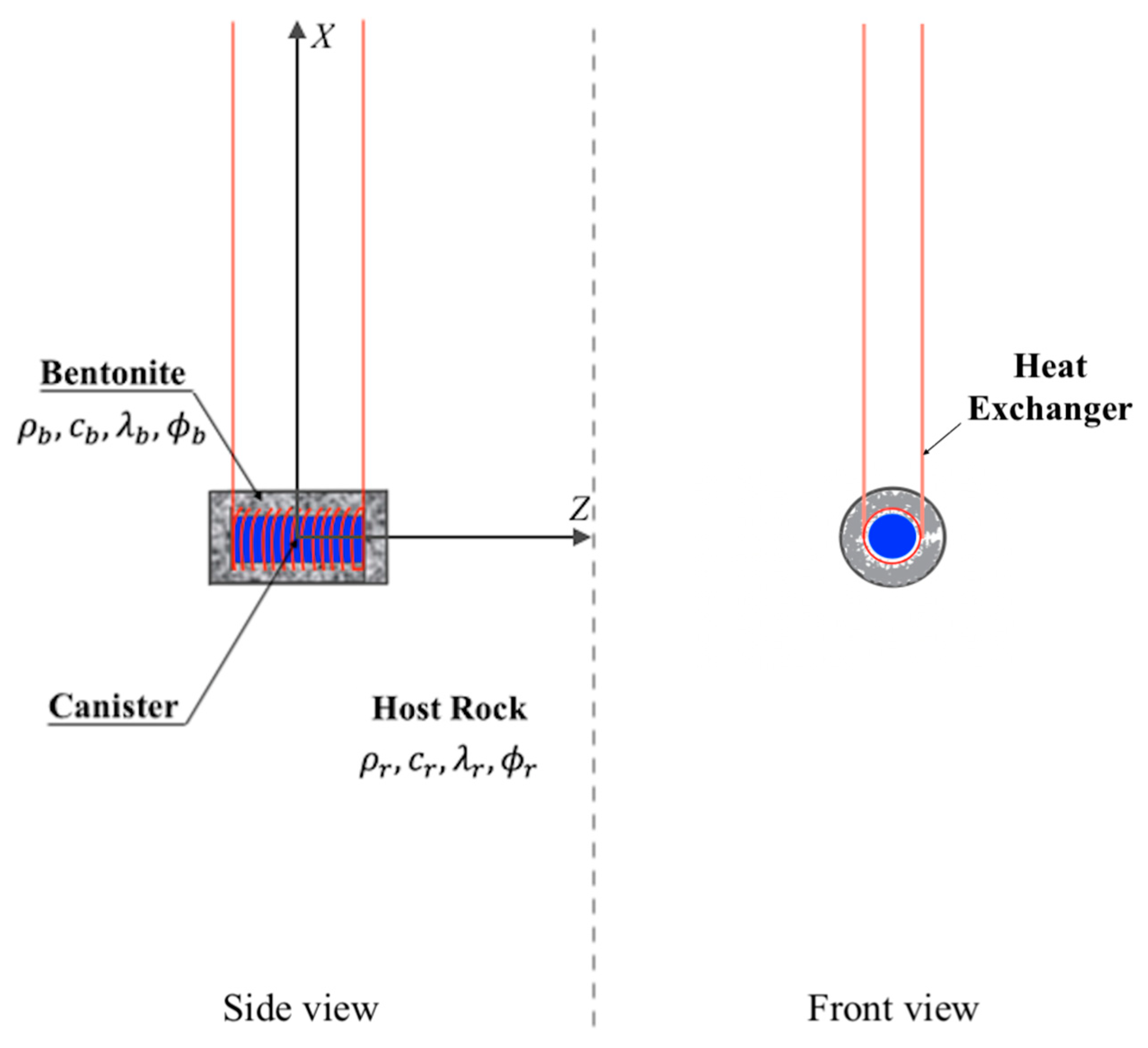
Figure 3.
Mesh used for the model, not to scale: Point A is located at r = 0.479 m; B is located at r = 1.13 m in the bentonite next to the bentonite–host rock interface; C is located in host rock next to the bentonite–host rock interface with r = 1.29 m; and D is 11.07 m away from the bentonite–host rock interface [21,23].
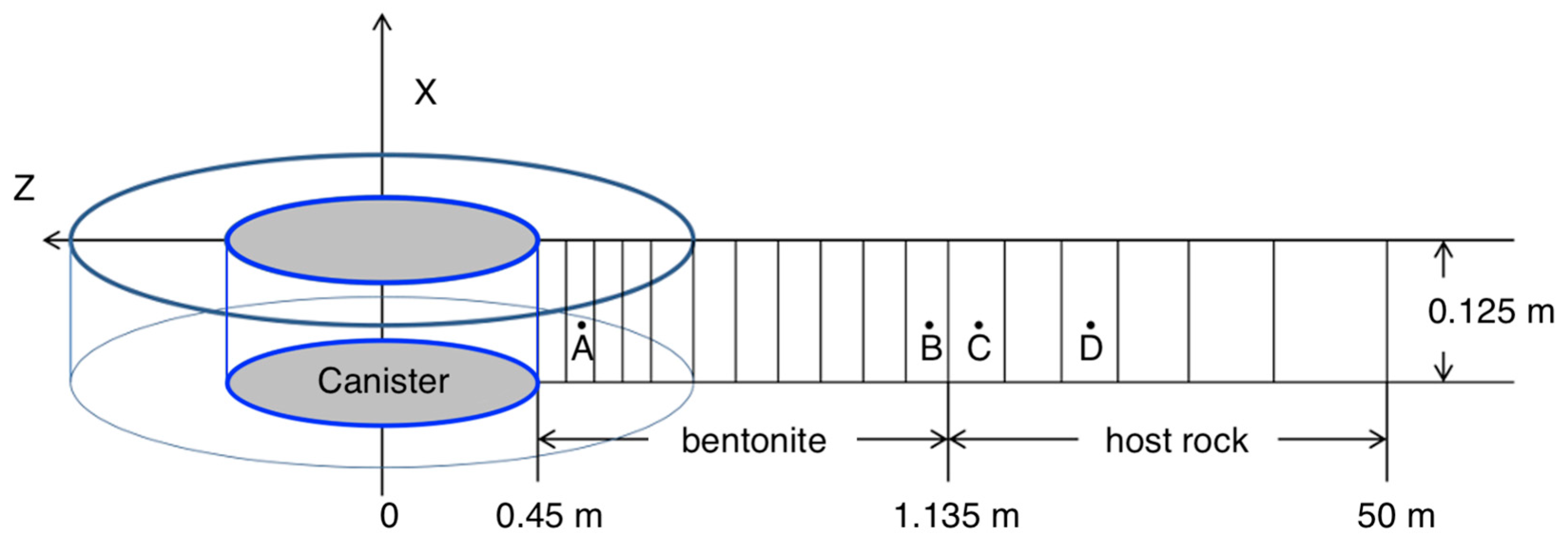
Figure 4.
Ground source heat pump system utilizing SNF/HLW.
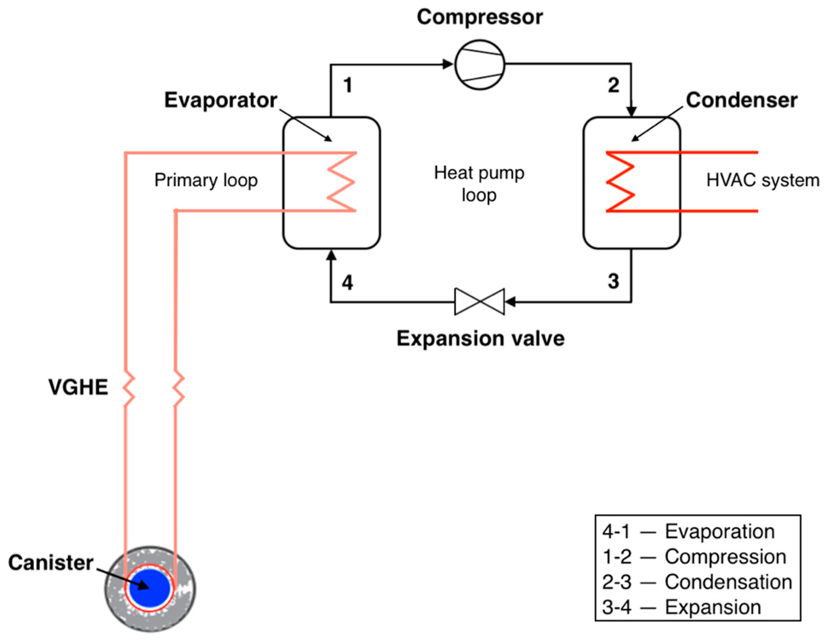
Figure 5.
Components of a typical organic Rankine cycle (ORC) system.

Figure 6.
Temperature evolution at varying spatial points and canister heat output.

Figure 7.
P-h diagram for the HPS refrigerant (R141b) at (a) 1 year after canister emplacement; (b) 10 years after canister emplacement; and (c) 30 years after canister emplacement.
Figure 7.
P-h diagram for the HPS refrigerant (R141b) at (a) 1 year after canister emplacement; (b) 10 years after canister emplacement; and (c) 30 years after canister emplacement.
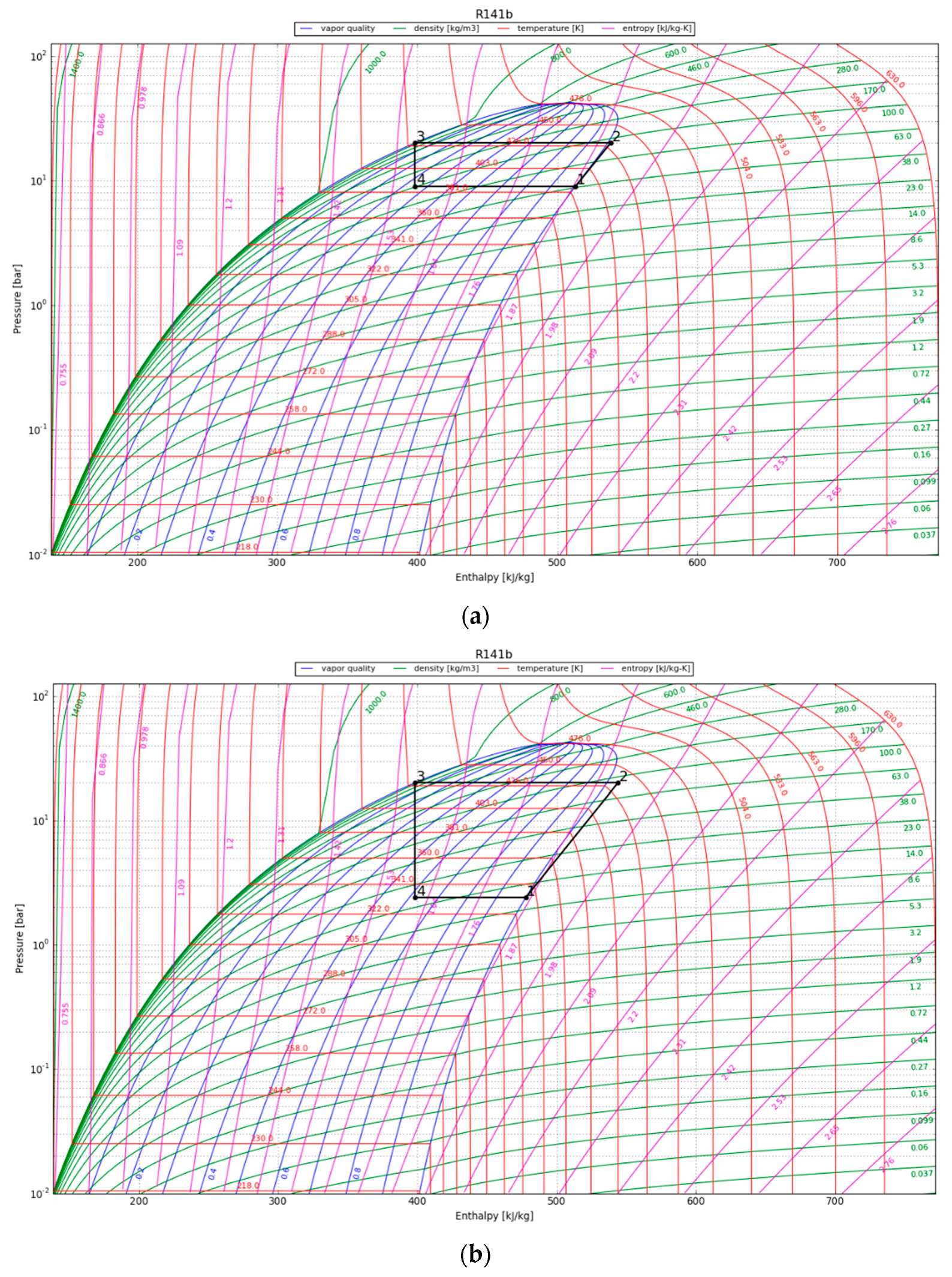
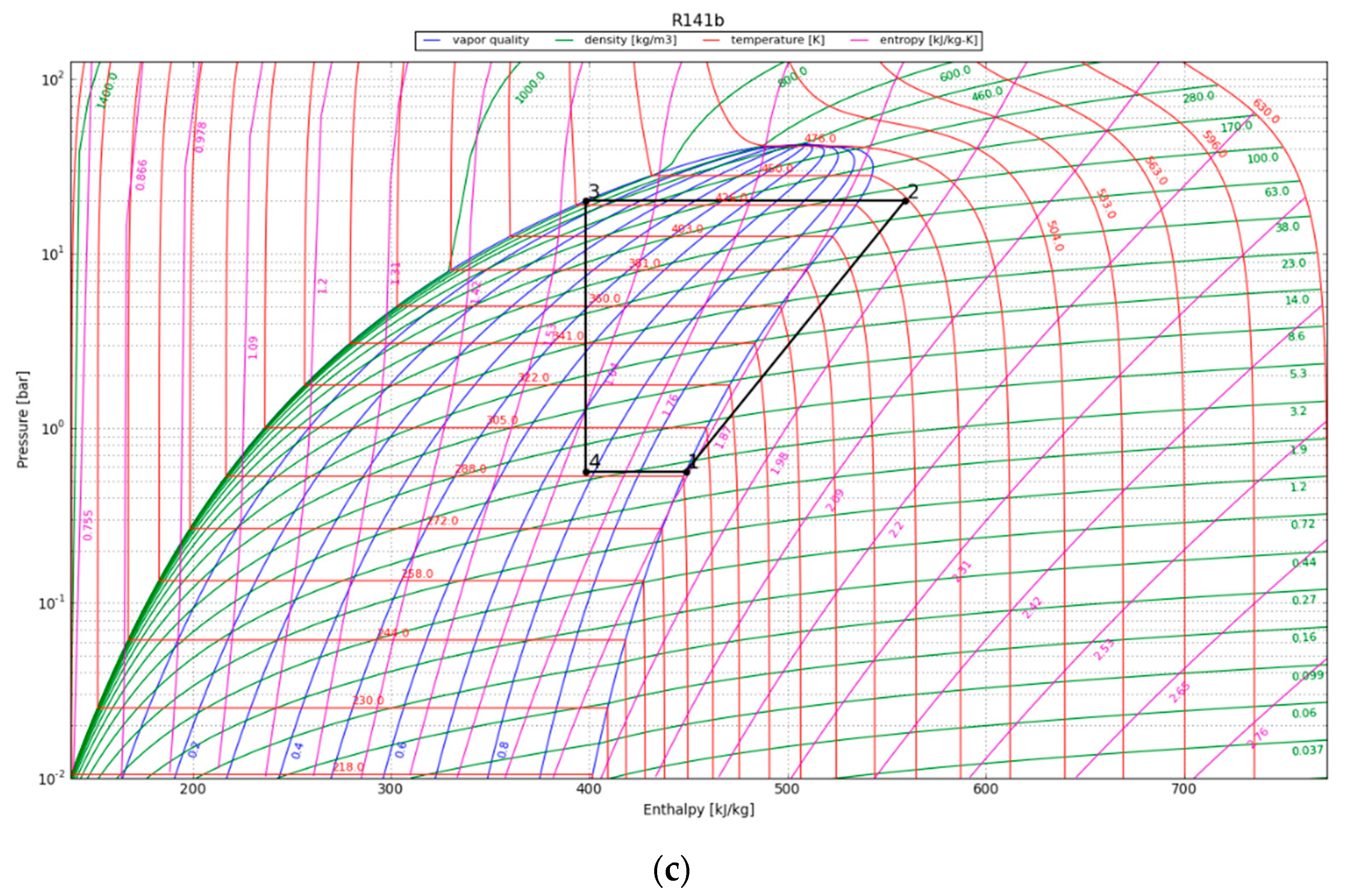
Figure 8.
The working cycle of the ORC system with refrigerant R142b at (a) 1 year after canister emplacement; (b) 10 years after canister emplacement; and (c) 30 years after canister emplacement.
Figure 8.
The working cycle of the ORC system with refrigerant R142b at (a) 1 year after canister emplacement; (b) 10 years after canister emplacement; and (c) 30 years after canister emplacement.


Table 1.
Thermal and hydrodynamic parameters of FEBEX bentonite [21].
Table 1.
Thermal and hydrodynamic parameters of FEBEX bentonite [21].
| Parameter | Value |
|---|---|
| Grain density | 2780 [kg/m3] |
| Porosity | 0.41 |
| Saturated permeability | 2.15 × 10⁻²¹ [m2] |
| Van Genuchten α | 1.10 × 10⁻⁸ [1/Pa] |
| Van Genuchten m | 0.60 [m] |
| Compressibility | 6 [1/Pa] |
| Thermal expansion coefficient | 1.0 × 10⁻⁴ [1/°C] |
| Dry specific heat | 1091 [J/(kg × °C)] |
| Thermal conductivity dry/wet | 0.47/1.15 [J/(kg × °C)] |
| Effective vapor diffusion coefficient | 2.03 × 10⁻⁴ [m2/s] |
Table 2.
Thermodynamic properties of the refrigerant R141b [31].
Table 2.
Thermodynamic properties of the refrigerant R141b [31].
| Parameter | Value |
|---|---|
| Molecular weight | 116.95 [g/mol] |
| Boiling point | 32.05 [°C] |
| Freezing point | −107.00 [°C] |
| Critical temperature | 204.50 [°C] |
| Critical pressure | 4.25 [MPa] |
| GWP | 630.00 |
| ODP | 0.11 |
Table 3.
Assumptions for the heat pump system [31].
Table 3.
Assumptions for the heat pump system [31].
| Parameter | Value |
|---|---|
| Working fluid | R141b |
| Fluid flow rate | 0.5 [kg/s] |
| Pressure (at the condenser) | 2.0 [MPa] |
| Ambient temperature | 12.0 [°C] |
| Compressor type | centrifugal |
| Isentropic efficiency of the compressor | 0.7 |
| Parameter | Value |
|---|---|
| Working fluid | R142b |
| Fluid flow rate | 2 [kg/s] |
| Cooling water temperature | 12 [°C] |
| Pump type | centrifugal |
| Isentropic efficiency of the pump | 0.90 |
| Heat exchange efficiency | 0.80 |
| Heat losses from the turbine, pipeline, and pump | - |
| Generator efficiency | 0.95 |
Table 5.
Results obtained for the HPS.
| Temporal Point after Canister Emplacement [Years] | Bentonite Temperature [°C] | Refrigerant Temperature [°C] | Compressor Power [kW] | Condenser Heat out [kW] | Evaporator Heat in [kW] | COP |
|---|---|---|---|---|---|---|
| 1 | 226.0 | 113.2 | 12.5 | 69.9 | 57.4 | 5.6 |
| 10 | 192.0 | 59.2 | 33.1 | 72.8 | 39.8 | 2.2 |
| 30 | 124.0 | 16.5 | 55.2 | 80.5 | 25.2 | 1.5 |
Table 6.
Results obtained for the ORC.
| Temporal Point after Canister Emplacement [Years] | Bentonite Temperature [°C] | Heat Input [kW] | Refrigerant Temperature [°C] | Pump Power [kW] | Turbine Power [kWe] | Cycle Efficiency [%] |
|---|---|---|---|---|---|---|
| 1 | 226.0 | 1802.8 | 107.4 | 14.7 | 309.7 | 16.4 |
| 10 | 192.0 | 1656.6 | 54.7 | 3.7 | 165.9 | 9.8 |
| 30 | 124.0 | 1590.2 | 38.4 | 1.8 | 107.7 | 6.7 |
Disclaimer/Publisher’s Note: The statements, opinions and data contained in all publications are solely those of the individual author(s) and contributor(s) and not of MDPI and/or the editor(s). MDPI and/or the editor(s) disclaim responsibility for any injury to people or property resulting from any ideas, methods, instructions or products referred to in the content. |
© 2024 by the authors. Licensee MDPI, Basel, Switzerland. This article is an open access article distributed under the terms and conditions of the Creative Commons Attribution (CC BY) license (https://creativecommons.org/licenses/by/4.0/).
Share and Cite
MDPI and ACS Style
Sarsenbayev, D.; Zheng, L.; Ermakova, D.; Sharipov, R.; Wainwright, H.M. Harnessing Geothermal Energy Potential from High-Level Nuclear Waste Repositories. Energies 2024, 17, 2002. https://doi.org/10.3390/en17092002
AMA Style
Sarsenbayev D, Zheng L, Ermakova D, Sharipov R, Wainwright HM. Harnessing Geothermal Energy Potential from High-Level Nuclear Waste Repositories. Energies. 2024; 17(9):2002. https://doi.org/10.3390/en17092002
Chicago/Turabian StyleSarsenbayev, Dauren, Liange Zheng, Dinara Ermakova, Rashid Sharipov, and Haruko M. Wainwright. 2024. "Harnessing Geothermal Energy Potential from High-Level Nuclear Waste Repositories" Energies 17, no. 9: 2002. https://doi.org/10.3390/en17092002
Note that from the first issue of 2016, this journal uses article numbers instead of page numbers. See further details here.