Numerical Analysis on Gas Production Efficiency from Hydrate Deposits by Thermal Stimulation: Application to the Shenhu Area, South China Sea

Abstract
:
1. Introduction
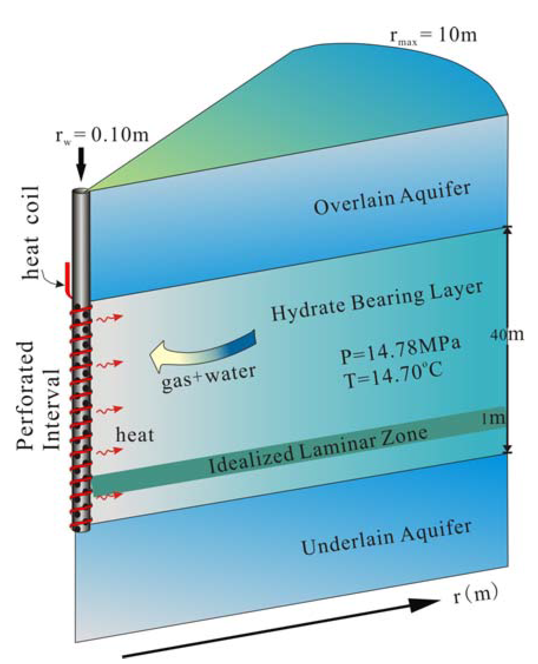
2. A Conceptual Model

3. A Numerical Model
4. Thermal Production Efficiency of Shenhu Hydrate Deposits
4.1. Reference Case


4.2. Sensitivity Analysis
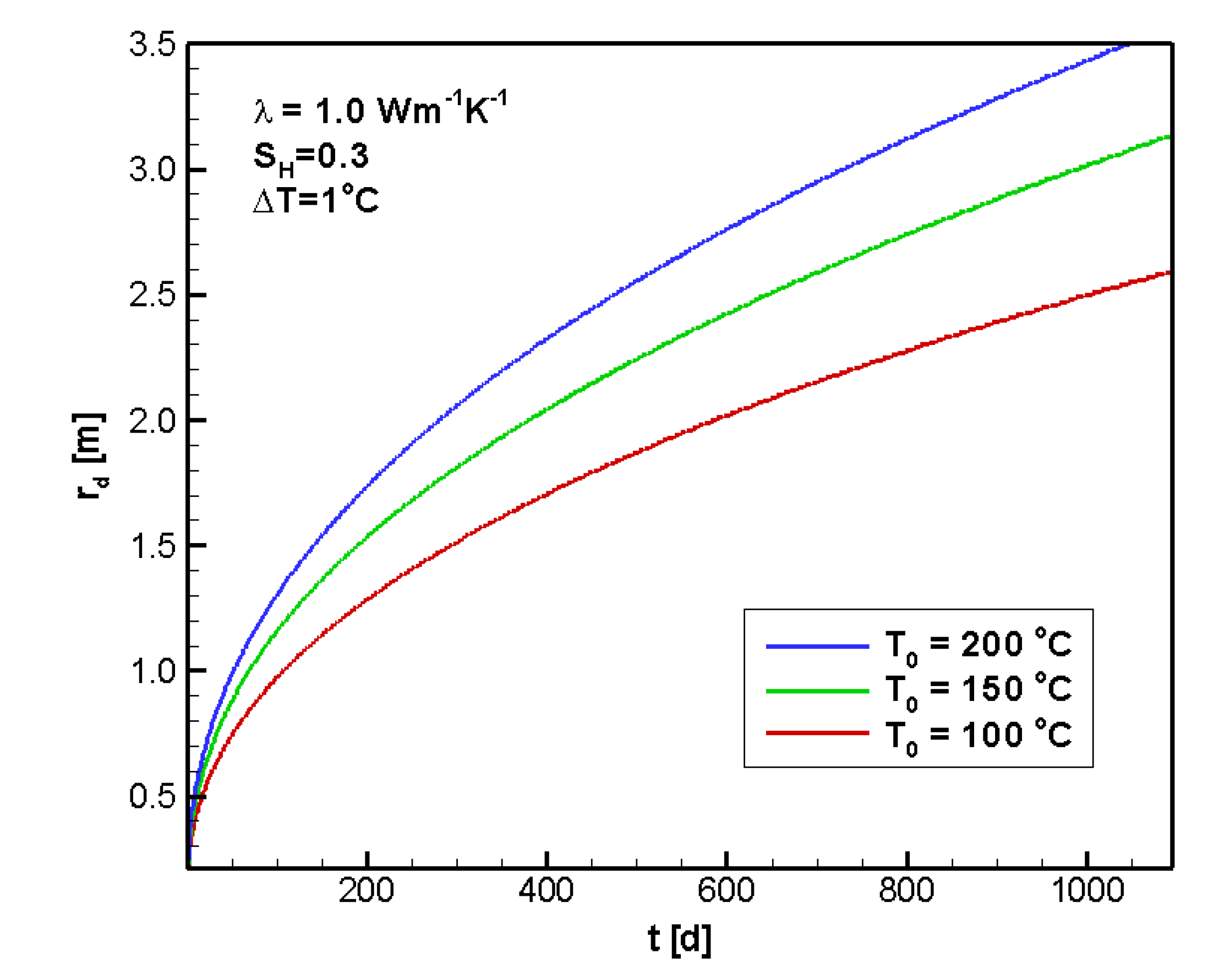
4.2.1. Sensitivity to T0
4.2.2. Sensitivity to ΔT

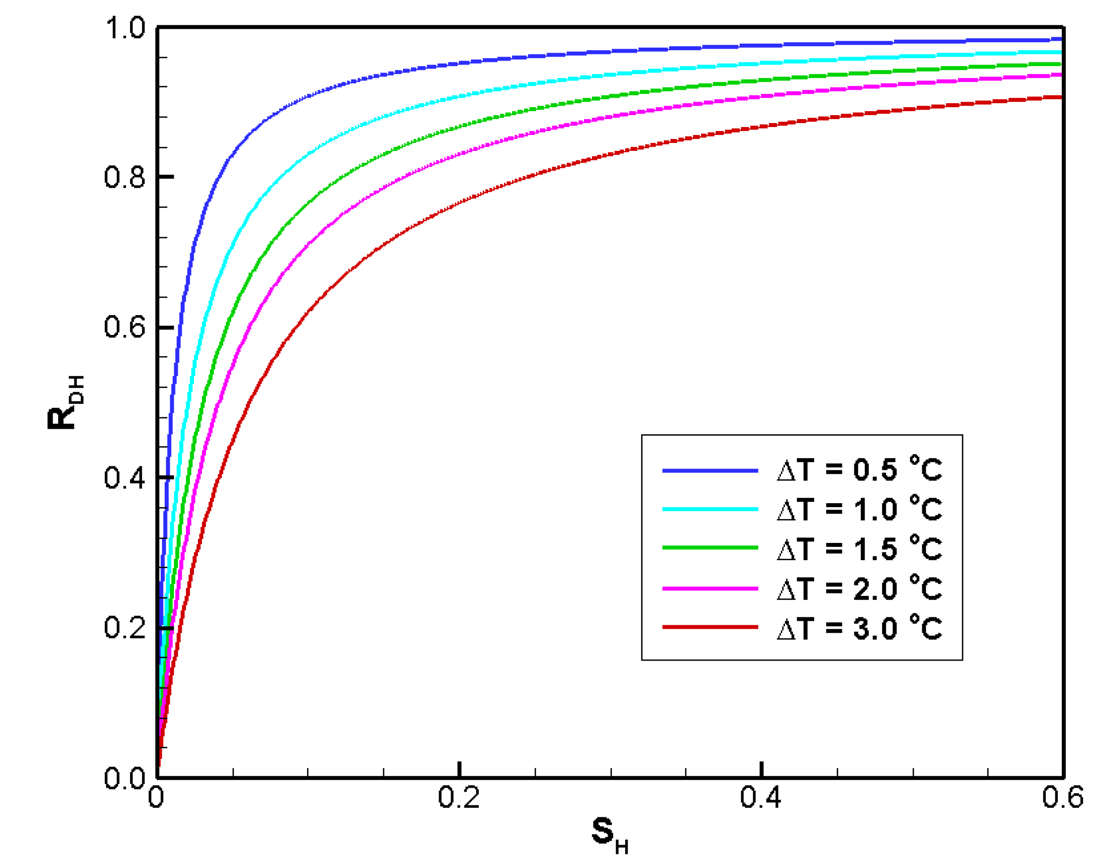
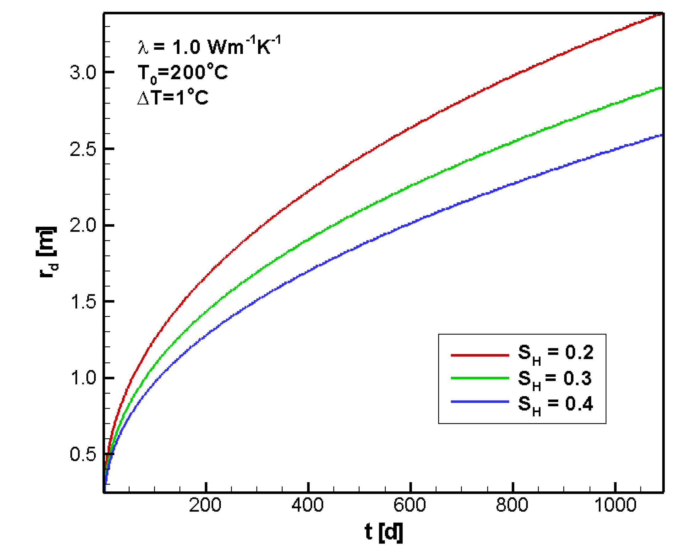
4.2.3. Sensitivity to SH
4.2.4. Sensitivity to λ

5. Discussion


6. Conclusions
Nomenclature:
| cp | heat capacity of sediment |
| cg | heat capacity of gas |
| cw | heat capacity of water |
| P | system pressure |
| ΔP | pressure difference in thermal production simulation |
| Q | total heat consumption, |
| QT | heat consumption for raising sediment temperature |
| QH | heat consumption for decomposing hydrate |
| QC | net combustion heat of methane gas |
| Qr | release rate of gas from hydrate deposit |
| qg | gas flux |
| qw | water flux |
| RDH | heat consumption efficiency of hydrate dissociation |
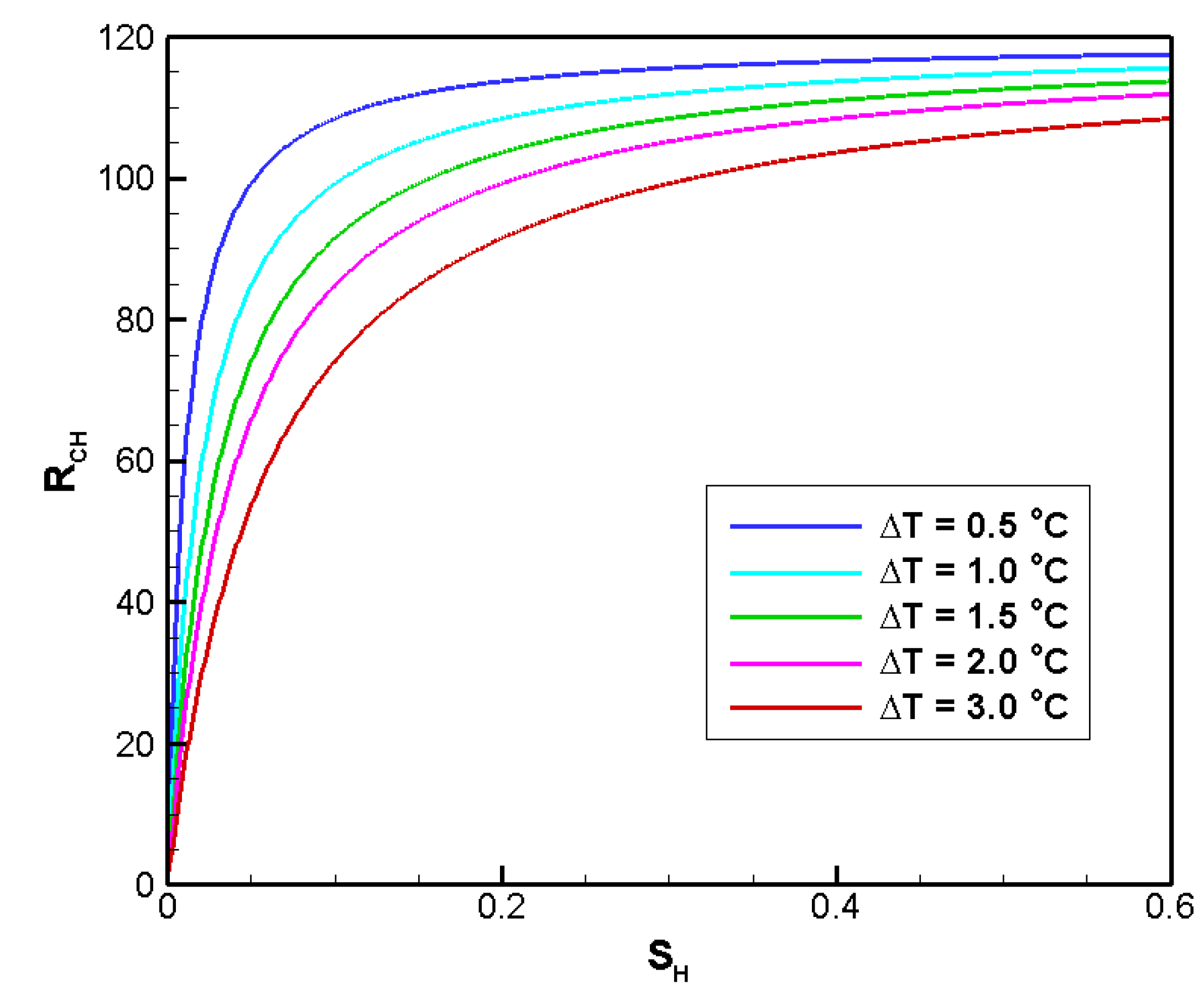
| RcH | energy efficiency of thermal hydrate exploitation |
| r | distance to vertical well |
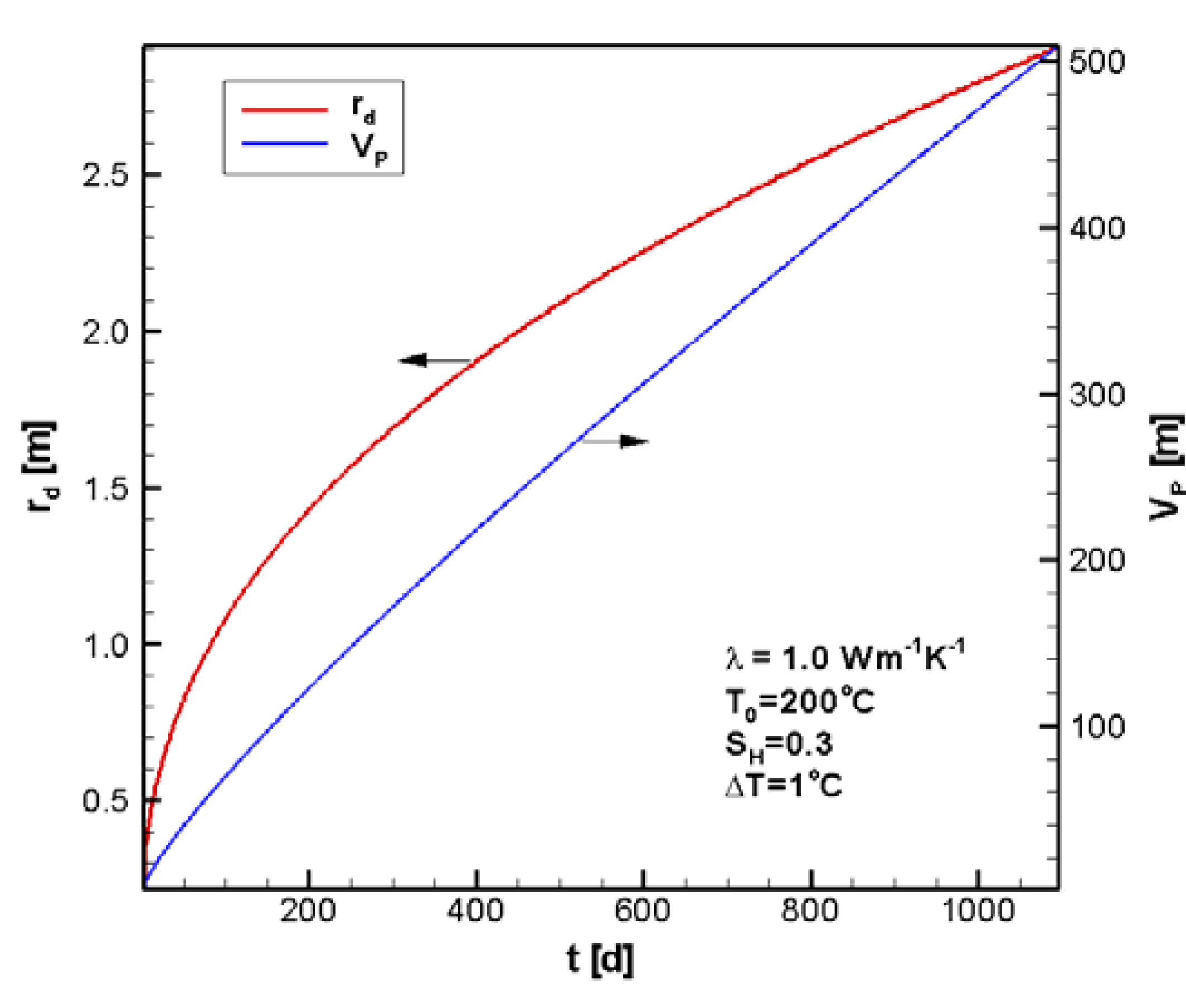
| rd | dissociation radius |
| rw | radius of vertical well, rw = 0.10 m |
| rmax | maximum radius of cylindrical domain simulated, rmax = 10 m |
| Δr | grid step in radius direction of cylindrical domain, Δr = 0.01 m |
| SH | hydrate saturation |
| T | system temperature |
| T0 | temperature at well |
| Te | hydrate phase equilibrium temperature |
| ΔT | temperature difference, |
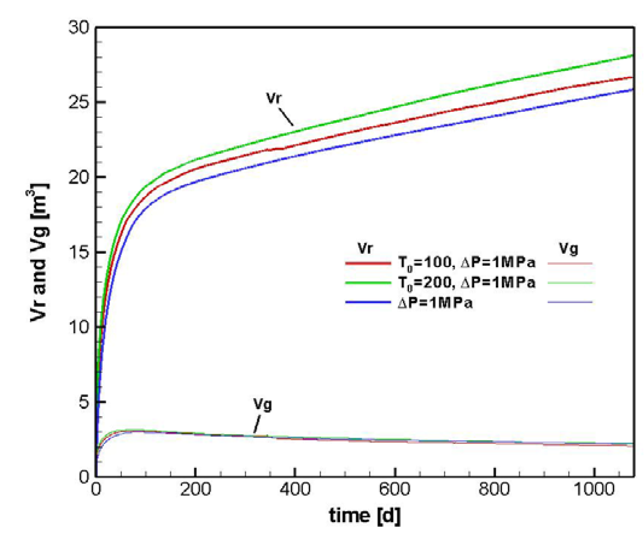
| Vg | cumulative volume of gas remained in reservoir |
| Vr | cumulative volume of gas released from hydrate deposit |
| z | system ordinate |
| Δz | discretized interval in vertical direction |
porosity of sediment | |
| ρ | density of sediment |
| λ | thermal conductivity of sediment |
| ΔH | decomposition enthalpy of methane hydrate |
| Δη | net calorific value of methane gas |
Acknowledgements
References
- Sloan, E.D. Clathrate Hydrates of Nautral Gases; Marcel Decker, Inc.: New York, NY, USA, 1998. [Google Scholar]
- Moridis, G.J.; Collett, T.; Dallimore, S.; Satoh, T.; Hancock, S.; Weatherhill, B. Numerical studies of gas production from several methane hydrate zones at the Mallik site, Mackenzie Delta, Canada. J. Pet. Sci. Eng. 2004, 43, 219–239. [Google Scholar] [CrossRef]
- Moridis, G.J.; Reagan, M.T.; Kim, S.-J.; Seol, Y.; Zhang, K. Evaluation of the gas production potential of marine hydrate deposits in the Ulleung Basin of the Korean East Sea. In Proceedings of 2007 SPE Asia Pacific Oil & Gas Conference and Exhibition, Jakarta, Indonesia, 30 October–1 November 2007.
- Moridis, G.J.; Reagan, M.T. Strategies for gas production from oceanic Class 3 hydrate accumulations. In Proceedings of OTC 18865,2007 Offshore Technology Conference, Houston, TX, USA, 30 April–3 May 2007.
- Moridis, G.J.; Reagan, M.T. Gas production from oceanic Class 2 hydrate accumulations. In Proceedings of 2007 Offshore Technology Conference, Houston, TX, USA, 30 April–3 May 2007.
- Moridis, G.J.; Kowalsky, M.B.; Pruess, K. Depressurization-Induced gas production from Class 1 hydrate deposits. In Proceedings of 2005 SPE Annual Technical Conference and Exhibition, Dallas, TX, USA, 9–12 October 2005.
- Moridis, G.J.; Collett, T.S.; Boswell, R.; Kurihara, M.; Reagan, M.T.; Koh, C.; Sloan, E.D. Toward production from gas hydrates: Current status, assessment of resources,and simulation-based evaluation of technology and potential. In Proceedings of 2008 Unconventional Reservoirs Conference, Keystone, CO, USA, 11–13 February 2008.
- Su, Z.; Zhang, K.; Moridis, G.J.; Yang, R.; Wu, N. Numerical investigation of gas production strategy for the hydrate deposits in the Shenhu area. In Proceedings of 2010 Offshore Technology Conference, Houston, TX, USA, 3–6 May 2010.
- McDonnell, S.L.; Max, M.D.; Cherkis, N.Z.; Czarnecki, M.F. Tectono-sedimentary controls on the likelihood of gas hydrate occurrence near Taiwan. Mar. Pet. Geol. 2000, 17, 929–936. [Google Scholar] [CrossRef]
- Wang, P.; Prell, W.; Blum, P. Ocean Drilling Program Leg 184 Scientific Prospectus South China Sea; Ocean Drilling Program: College Station, TX, USA, 2000; pp. 1–97. [Google Scholar]
- Wu, N.; Yang, S.; Zhang, H.; Liang, J.; Wang, H.; Su, X.; Fu, S. Preliminary discussion on gas hydrate reservoir system of Shenhu Area, North Slope of South China Sea. In Proceedings of the 6th International Conference on Gas Hydrates (ICGH 2008), Vancouver, Canada, 6–10 July 2008.
- Wu, N.; Yang, S.; Zhang, H.; Liang, J.; Wang, H.; Lu, J. Gas Hydrate System of Shenhu Area,Northern South China Sea: Wire-line Logging, Geochemical Results and Preliminary Resources Estimates. In Proceedings of 2010 Offshore Technology Conference, Houston, TX, USA, 3–6 May 2010.
- Chen, D.; Cathles, L.M. On the thermal impact of gas venting and hydrate crystallization. J. Geophys. Res. 2005, 110, B11204:1–B11204:13. [Google Scholar]
- Duan, Z.; Miller, N.; Greenberg, J. The prediction of methane solubility in natural waters to high ionic strengths from 0 to 250 °C and from 0 to 1600 bar. Geochim. Cosmochim. Acta 1992, 56, 1451–1460. [Google Scholar] [CrossRef]
- Kim, H.C.; Bishnoi, P.R.; Heidemann, R.A.; Rizvi, S.S.H. Kinetics of Methane Hydrate Decomposition. Chem. Eng. Sci. 1987, 42, 1645. [Google Scholar] [CrossRef]
- Clarke, M.A.; Bishnoi, P.R. Determination of the Intrinsic Rate of Methane Gas Hydrate Decomposition. Chem. Eng. Sci. 2000, 55, 4869. [Google Scholar] [CrossRef]
© 2011 by the authors; licensee MDPI, Basel, Switzerland. This article is an open access article distributed under the terms and conditions of the Creative Commons Attribution license (http://creativecommons.org/licenses/by/3.0/).
Share and Cite
Su, Z.; Cao, Y.; Wu, N.; He, Y. Numerical Analysis on Gas Production Efficiency from Hydrate Deposits by Thermal Stimulation: Application to the Shenhu Area, South China Sea. Energies 2011, 4, 294-313. https://doi.org/10.3390/en4020294
Su Z, Cao Y, Wu N, He Y. Numerical Analysis on Gas Production Efficiency from Hydrate Deposits by Thermal Stimulation: Application to the Shenhu Area, South China Sea. Energies. 2011; 4(2):294-313. https://doi.org/10.3390/en4020294
Chicago/Turabian StyleSu, Zheng, Yuncheng Cao, Nengyou Wu, and Yong He. 2011. "Numerical Analysis on Gas Production Efficiency from Hydrate Deposits by Thermal Stimulation: Application to the Shenhu Area, South China Sea" Energies 4, no. 2: 294-313. https://doi.org/10.3390/en4020294