Article

Electrical Performance and Carbon Deposition Differences between the Bi-Layer Interconnector and Conventional Straight Interconnector Solid Oxide Fuel Cell

1
Key Laboratory of Thermo-Fluid Science and Engineering, Ministry of Education, Xi'an Jiaotong University, Xi'an 710049, Shaanxi, China
2
Nuclear Safety Technology Research Center, Suzhou Nuclear Power Institute, Xihuan Road 1788#, Suzhou 215004, Jiangsu, China
3
Department of Mechanical Engineering, Virginia Tech, Blacksburg, VA 24060, USA
*
Author to whom correspondence should be addressed.
Energies 2014, 7(7), 4601-4613; https://doi.org/10.3390/en7074601
Submission received: 20 May 2014 / Revised: 7 July 2014 / Accepted: 16 July 2014 / Published: 22 July 2014
(This article belongs to the Special Issue Reacting Transport Phenomena in Solid Oxide Fuel Cells)

Abstract

:
Carbon deposition considered in a solid oxide fuel cell (SOFC) model may be influenced by the operating voltage, inlet water/methane ratio, working temperature and pressure, inlet molar fraction of fuel and so on. The effects of these parameters in a planar SOFC implementing a novel bi-layer interconnector are not well understood. This paper is focused on the numerical study of carbon deposition and electrical performance of a bi-layer interconnector planar SOFC. The results illustrate that the electrical performance of the bi-layer interconnector SOFC is 11% higher than that of the conventional straight interconnector SOFC with initial state. After 120 days of operation, the electrical performance of the bi-layer interconnector SOFC has a slight decrease and more carbon deposit because of the increased electrochemical reaction rate. However, these differences minimize if higher operating voltages are involved.

Graphical Abstract

1. Introduction

With the industrialization of modern society, the world is faced with the serious problem of environmental pollution. Several entities are conducting extensive research towards clean and renewable energy. Solid oxide fuel cells (SOFCs) have also been investigated as part of this effort. SOFCs have the advantage of having a high efficiency of energy conversion and low carbon emission [1]. Therefore, several research institutions, specialists and scholars have devoted themselves to developing more efficient SOFCs using both experiments as well as numerical methods.
There are several reasons which influence the efficiency of SOFCs [2], amongst which are the structure of the interconnector and carbon deposition on the anode. Both of these are extremely important since they can influence the state of flow, as well as the mass transfer in the gas channel and porous layer. Many researchers have focused heavily on these two areas: For the optimization of the interconnector, a protruding design was proposed by Li et al. [3] to enhance the mass transfer ability of the gas channel. Yuan et al. [4] have found through numerical simulations, that the mass transfer rate, aspect ratio and base angle have significant effects on the thermal-hydraulic parameters. Kong et al. [5] and Liu et al. [6] optimized the size of the gas channel for cathode-supported SOFCs and proton-conductive SOFCs with a direct interconnector. Nguyen et al. [7] proposed a ribbed interconnector SOFC. A circular planar SOFC with ribs was also reported in reference [8]. Many researchers experimentally analyzed the influence of several factors (catalyst activity, temperature, type of fuel and so on) on carbon deposition in a SOFC [9,10,11,12,13,14]. The damage due to carbon deposition in a SOFC under operation, fueled with tar-laden biomass gas was numerically studied by Singh et al. [15]. Effective ways to minimize the carbon deposition in SOFCs were also studied by several researchers [16,17,18,19,20].
However, all these studies examine either the effect of novel interconnector designs neglecting carbon deposition, or the phenomenon of carbon deposition on conventional interconnector SOFCs. There is no numerical data available on carbon deposition in a SOFC with a novel bi-layer interconnector design. The influence of carbon deposition on the performance of a new interconnector design has been numerically studied by COMSOL Multiphysics 3.5 in this paper. The design under consideration is based on the bi-layer interconnector we have proposed in previously published papers [21,22]. The porosity, catalyst activity, current density and amount of carbon deposition are considered through comparison of conventional direct interconnector SOFC and bi-layer interconnector SOFC. The results show that the bi-layer interconnector could cause more carbon deposition due to more electrochemical reactions were include.

2. Physical Model

2.1. Geometric Model

Figure 1 illustrates the structure of a bi-layer interconnector SOFC, which is formed by several positive-electrolyte-negative layers (PENs). The bi-layer interconnectors are used for joining these PENs. The specific structure and operating principle can be found in references [21,22]. Bi-layer interconnectors not only enhance mass transfer, but also collect the current produced by SOFCs.
Figure 1. Schematic plot of bi-layer interconnector solid oxide fuel cell (SOFC) in the references [21,22]. Reprinted/Reproduced with permission from [21]. Copyright 2011 Elsevier.
Energies 07 04601 g001
Figure 2 is the schematic of two 2D carbon deposition SOFC models. One consists of the bi-layer interconnector, and the other does not. The diameter of the ribs in the gas channel of the bi-layer interconnector SOFC model are 0.5 mm (H), 3 mm (W) and 3 mm (S), respectively. The porous materials of the anode and cathode are homogenous. The anode material is Ni/yttria stabilized zirconia (Ni/YSZ) where the gas is composed of O2 and N2. The cathode material is lanthanum strontium manganate (LSM)/YSZ purged with CH4, O2, H2O, CO and CO2. The model is divided into seven layers: fuel channel, anode support layer, anode reaction layer, electrolyte, cathode reaction layer, cathode support layer and air channel, where electrochemical reactions only happen in electrode reaction layers. The gases are as assumed to be laminar and ideal flow and the Reynolds number in gas channel is chosen to be 20 in this paper. The operating voltage of the fuel cell is constant. All the cases are operating in 1073 K and 1 atm, the velocity of both oxidizing agent and reducing agent remain the same with 4 m/s. The other related operating parameters and physical dimension of the model are the same as that in literature [20].
Figure 2. The schematic of the SOFC model with: (a) conventional straight interconnector; and (b) bi-layer interconnector.
Energies 07 04601 g002

2.2. Mathematical Model

When comparing the models with and without ribs, we consider both models at the initial state and again after 120 days in operation. COMSOL Multiphysics is used to couple the Navier-Stokes (N-S) equations, mass transfer equations, energy equations and charge balance equations.
Unsteady N-S equations are used to study the flow characteristics of the gas in the gas channels. Due to the porosity characteristics of the electrode reaction layers and electrode support layers, unsteady state Brinkman equations are implemented. Because of the high working temperature of SOFCs, the gas density can be obtained by the state equation of ideal gas. The governing equations are as follows:
Energies 07 04601 i001
Energies 07 04601 i002
The dynamic viscosity of the inlet gas is written as:
Energies 07 04601 i003
where ηi is the dynamic viscosity of species i.
The fuel and air channel inlets are maintained with fuel and air at a steady velocity, while a pressure boundary condition is imposed on the outlets.
Dusty-gas model is chosen to study the mass transfer performance of the multicomponent diffusion in gas channels and porous layers:
Energies 07 04601 i004
Here, the effective binary diffusion coefficient Dijeff of component i and j in gas channels and porous layers was obtained from literature [23]:
Energies 07 04601 i005
Established mass fraction of fuel and air is given at the inlet of gas channels [20].
For the charge transfer equations, this study has chosen effective electron and ion conductivity as the physical property of the related materials. The governing equations are given as:
Energies 07 04601 i006
The upper boundary of the anode support layer is assumed as ground and the lower boundary of this layer is at the operating voltage of the cell. The interface of electrode reaction layers and electrolyte layer keeps continuity.
Butler-Volmer equations are used to obtain the current density that is produced by electrochemical reactions and the open circuit voltage (OCV) is expressed by Nernst equation:
Energies 07 04601 i007
Energies 07 04601 i008
Because of difficulty in measuring the local temperature in a working SOFC, majority of the related studies have chosen porous local thermal equilibrium model: Alazmi et al. [24] and Kim et al. [25] use this model to study the characterastics of porous media. Damm et al. [26] and Andersson et al. [27] find that it is necessary to use this model to obtain the temperature distribution especially there is an internal heat source caused by current, such as in SOFC. This is also the case in the current study:
Energies 07 04601 i009
here Sq is the source term of heat transfer equations. A constant temperature condition and a heat convection condition are imposed on the inlets and outlets, respectively. All the source terms mentioned in the above equations can be found in literature [20].
When we consider the carbon deposition, the graphite produced by methane cracked reaction and Boudouard reaction will be absorbed at the surface of the catalyst. Because of the porosity characteristics mentioned above, it is difficult for the catalyst to desorb the carbon. Based on the porosity variation rate we have investigated [20], the permeability of the porous layer is changed:
Energies 07 04601 i010
Energies 07 04601 i011
The interface between porous support layer and reaction layer is assumed to be continuous. The models are calculated by COMSOL Multiphysics and the components of inlet fuel are listed in Table 1 [23].
The SOFC model and chemical reaction kinetics model have been validated in our previous work [20]. The verification of grid independence is shown in Figure 3 and Figure 4. The elements of Grid-1 and Grid-2 are 2760 and 5120, respectively. For the average absolute deviation between these two models is lower than 0.015%, this study has chosen a mesh similar to Grid-1.
Table 1. Molar fraction of inlet fuel.
Component of inlet fuelInlet molar fractionBasic case inlet molar fraction
H2O0.1710.5
CH40.2630.5
CO0.4930
CO20.0290
H20.0440
Figure 3. Schematic plot of grids.
Energies 07 04601 g003
Figure 4. Grids independence test: (a) I-V; and (b) temperature.
Energies 07 04601 g004

3. Results and Discussion

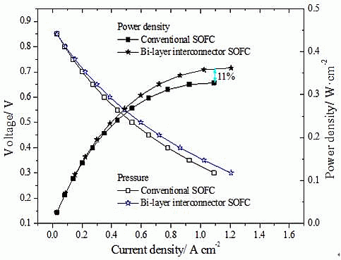
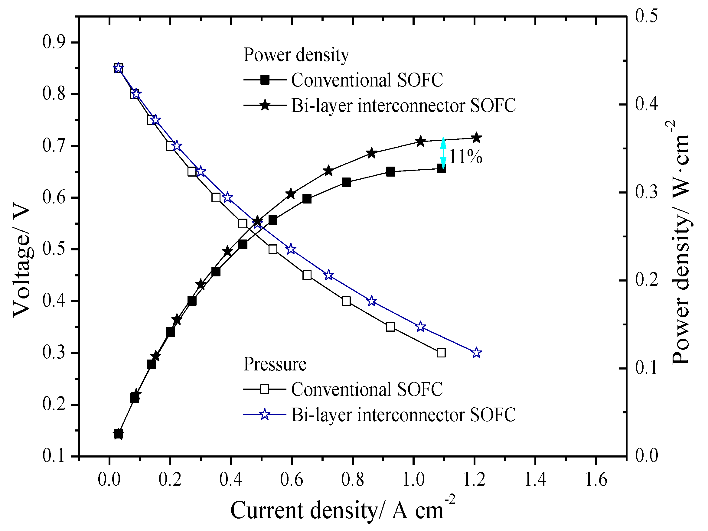
3.1. Original Steady State Electrical Properties

Comparing the models with straight channel interconnector and bi-layer interconnector, the results of initial steady state models show that electrical performance of the SOFC model with bi-layer interconnector is better than that of conventional interconnector, as shown in Figure 5. There is no lessening of ohmic polarization because the model is 2D. At the very beginning, both cases are almost with the same current density and circuit voltage, but when the current density is increasing to 0.1 A/cm2, there have some differences: the voltage of bi-layer interconnector SOFC is higher than that of conventional models if the models are working with the same current density. In other words, with the same working voltage, model with bi-layer interconnector has higher current density. This result means a higher power density: when the current density is rising to 1.1 A/cm2, the power density of the two cases has already presenting a divergence up to 11%. The bi-layer interconnector could increase the velocity of the fuel gas both in the porous layer and at the interface between anode and electrolyte (triple phase boundary, TPB), more gas is spreading into these porous layers and replenishing the consumed fuel gas, thus relieve the demand of fuel in short supply. The enhanced mass transfer ability would largely lessen the concentration gradient in reaction layers, reduced concentration gradient leads to less concentration polarization loss and more electrochemical reactions are happened. Precisely because of these reasons, the electrical property of the bi-layer interconnector SOFC model is better than the conventional straight one.
Figure 5. The electrical properties of steady state models with different interconnector.
Energies 07 04601 g005

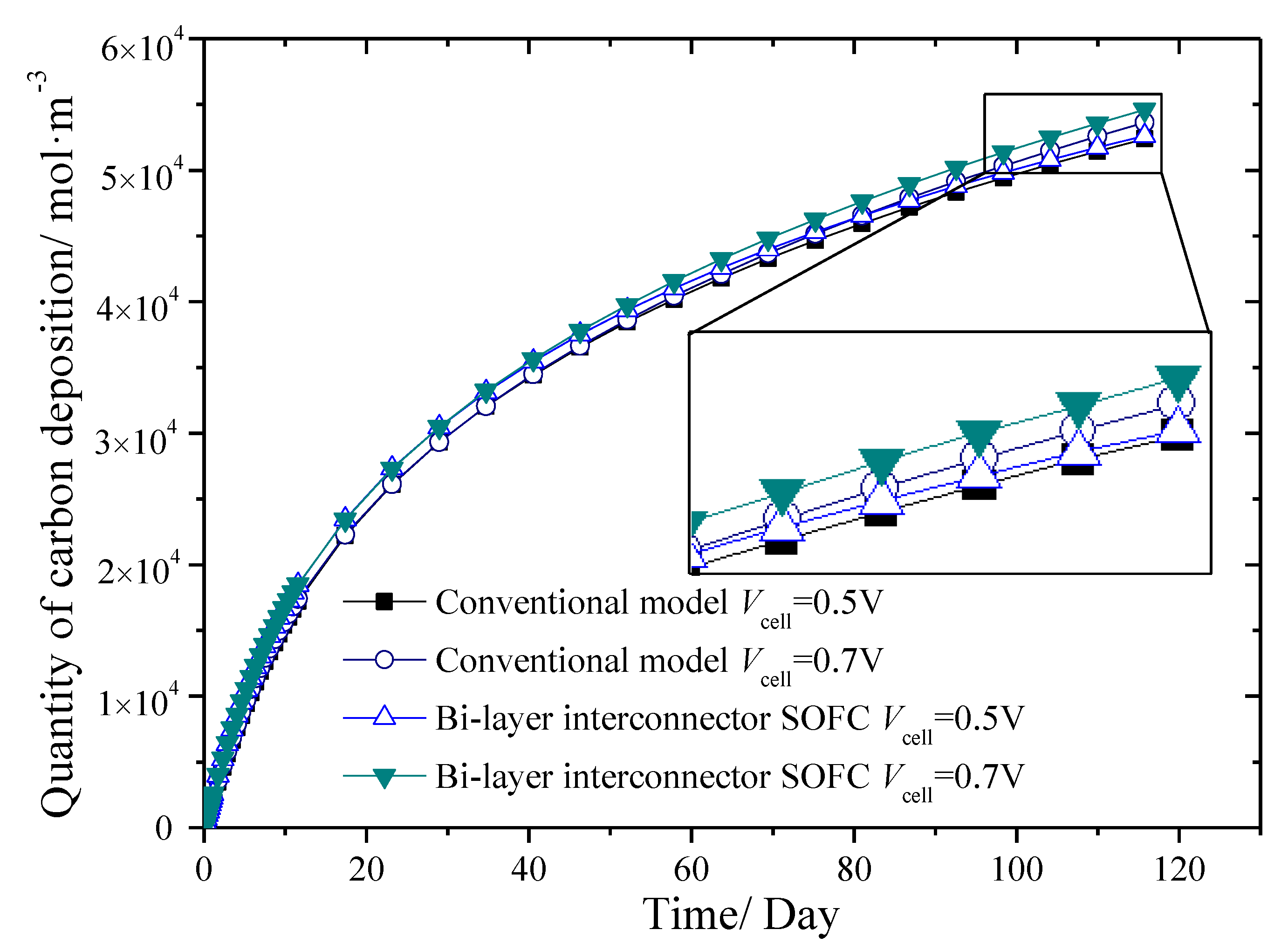
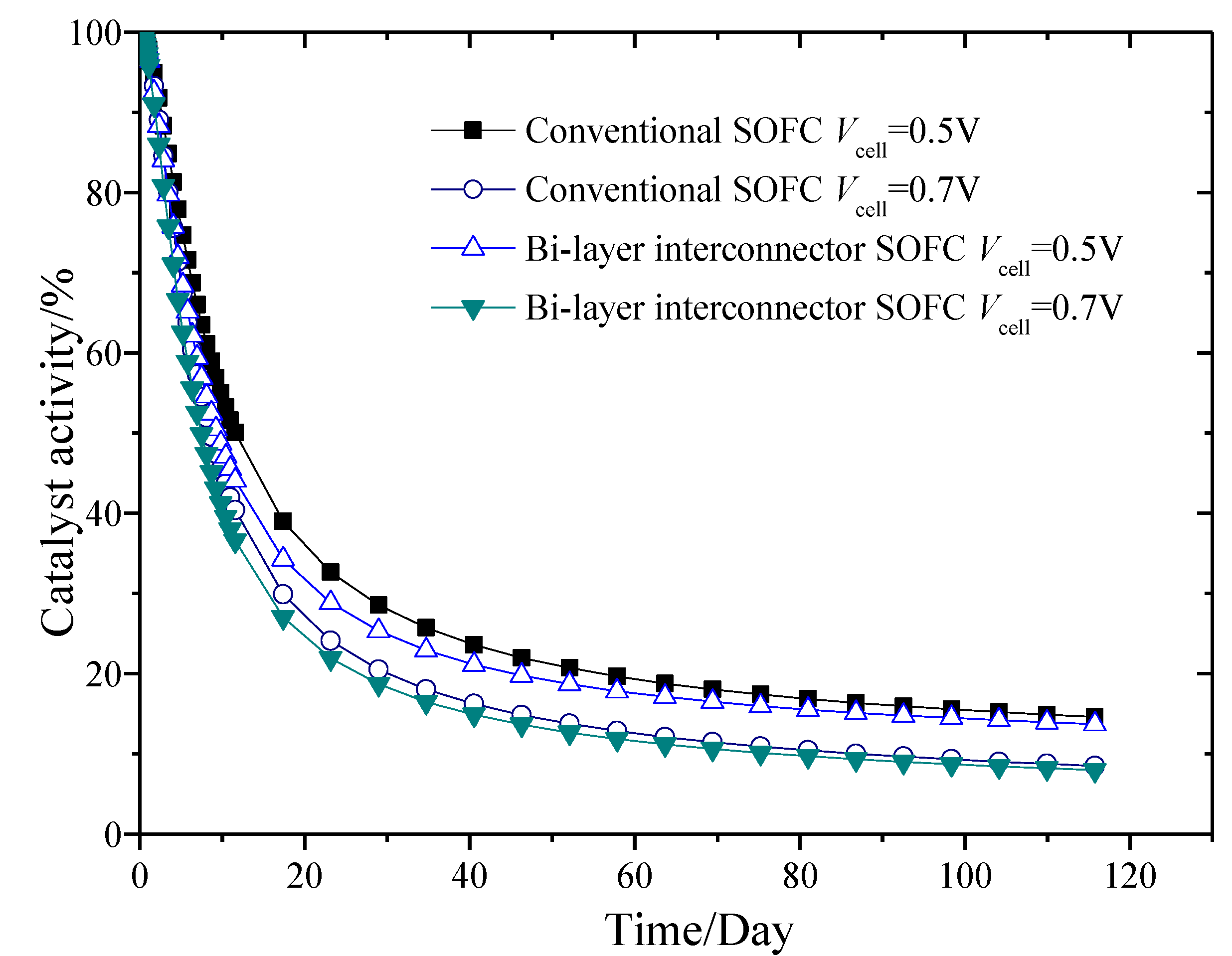
3.2. Unsteady State Performance of Models with Different Interconnectors

The variations of several electrical performance parameters, including the quality of carbon deposition, porosity, catalyst activity and current density have been investigated. As for the bi-layer interconnector model, the ribs disturb the fuel in the gas channel and porous layer of anode, which enhance mass transfer of the fuel and increase reaction rate of each electrochemical reaction. The reaction rate of methane cracked reaction which produces carbon may also have been enhanced, and thus in the bi-layer interconnector model, the quantity of carbon deposition is slightly higher than that of the conventional SOFC model, as shown in Figure 6. Because of the enhanced mass transfer ability, there is a sharper decrease in both the porosity and catalyst activity in the bi-layer interconnector SOFC as compared to the conventional SOFC. Figure 6 also indicates that the higher the working voltage is, the more carbon is formed.
From Figure 6, Figure 7, Figure 8 and Figure 9, it can be observed that the operating voltage has little impact on the variation of the amount of carbon deposited and the porosity of SOFC models with different interconnectors. However, it affects the catalyst activity and the current density more obviously. In Figure 6, it could be found that when the operating voltage is 0.5 V, the quantity of carbon deposition is almost the same in both cases, but when the voltage is increased to 0.7 V, the carbon quantity differences between the bi-layer interconnector SOFC model and the conventional one is becoming obviously.
Figure 6. Quantity of carbon deposition for SOFC models with different interconnectors.
Energies 07 04601 g006
Figure 7. Variation of porosity for SOFC models with different interconnectors.
Energies 07 04601 g007
This phenomenon could also be found in Figure 8: the size of the pore in porous layer becomes smaller if bi-layer interconnector is used, the descending rate of porosity would increase if voltage is rising. That is because enhanced mass transfer ability also means an even faster electrochemical reaction rate, the formed carbon would cover on the surface of pore in porous layers, more carbon gathers thus causes the shrinking of porosity. Catalyst activity has only a slight change in both cases with different interconnector, but the operating voltage would have more obviously influence on it, just as shown in Figure 8. For both conventional and bi-layer interconnector SOFC model, a higher operating voltage leads to more carbon deposition, smaller porosity, decreasing catalyst activity and current density.
Figure 8. Variation of catalyst activity for SOFC models with different interconnectors.
Energies 07 04601 g008
Figure 9 shows that the current density attenuation for the bi-layer interconnector is almost the same as the conventional interconnector when operating voltage is 0.7 V. After running for 120 days, current density reduces 53%. However, when the operating voltage decreases to 0.5 V, the damping of current density in the bi-layer interconnector SOFC model (39%) is inferior to that in the conventional SOFC model (41%).
Figure 9. Variation of current density for SOFC models with different interconnectors.
Energies 07 04601 g009

4. Conclusions

Unsteady models were developed in this paper to study the electrical performance and carbon deposition of conventional interconnector SOFC and bi-layer interconnector SOFC. In the case of bi-layer interconnector SOFC, carbon deposition on the surface of the porous structure in the anode decreases catalyst activity and narrows the holes of the porous layer, which leads to a decline in the electrical performance. The results show that the bi-layer interconnector improves the electrical performance of SOFC as compared to the conventional SOFC due to its enhanced mass transfer ability, but it also causes more carbon deposition. The porosity, catalyst activity and current density attenuation rate of the bi-layer interconnector has a slight decrease when compared with the conventional model. Operating voltage could also influence the quantity of carbon deposition. The higher the operating voltage, the more the carbon deposit. This result will be useful for researchers to look more closely to the mechanism of electrochemical reactions of SOFCs.

Acknowledgments

This work is supported by China National Funds for Distinguished Young Scientists (No. 51025623) and Doctoral Fund of Education of China (No. 20090201110009).

Author Contributions

The present model is developed by Min Yan and Pei Fu based on the research of Qiuyang Chen, Qiuwang Wang and Min Zeng are the reviewers of this paper, Jaideep Pandit is the author who checks the English spelling.

Nomenclature

cC
Molar concentration of carbon (mol·m−3)
cpi
Specific heat of species i at constant pressure (J·mol−1·K−1)
Dij
Binary diffusion coefficient (m2·s−1)
F
Faraday’s constant (96,487 C·mol−1)
J
Current density (A·m−2)
k
Thermal conductivity (W·m−1·K−1)
ki
Thermal conductivity of pure component i (W·m−1·K−1)
M
Molecular weight of species i (kg·mol−1)
mi
Mass of species i (kg)
Ni
Molar flux of species i (mol·m−2·s−1)
n
Moles of electrons transferred per mole reactant
ni
Moles of species i (mol)
p
Pressure (Pa)
pi
Partial pressure of species i (Pa)
Rg
Universal gas constant (8.3143 J·mol−1·K−1)
rC
Carbon deposition rate (mol·m−3·s−1)
Si
Source term of component i
T
Temperature (K)
t
Time (s)
u
Velocity vector (m·s−1)
Vi
Volume of species i (m3)
wi
Mass fraction of species i (%)
xi
Molar fraction of species i

Greek symbols

α
Catalyst activity (%)
σ
Electronic conductivity (S·m−1)
φel
Electronic potential (V)
φio
Ionic potential (V)
ε
Porosity
ηact
Electrode activation over-potential (V)
ρi
Density of species I (kg·m−3)
κ
Permeability
η
Dynamic viscosity
τ
Tortuosity

Subscripts

act
Activity
an
Anode
B
Boudouard reaction
C
Methane cracked reaction
ca
Cathode
cell
Fuel cell
pore
Porous media
R
Methane steam reforming reaction
re
Electrode reaction layer
S
CO water-gas shift reaction
st
Electrode support layer
total
Total amount
TPB
Triple phase boundary, the interface between anode and electrolyte
io
Ionic
el
Eelctronic

Superscripts

eff
Effective
T
Transposed matrix

Conflicts of Interest

The authors declare no conflict of interest.

References

  1. Najafi, B.; Shirazi, A.; Aminyavari, M.; Rinaldi, F.; Taylor, R.A. Exergetic, economic and environmental analyses and multi-objective optimization of an SOFC-gas turbine hybrid cycle coupled with an MSF desalination system. Desalination 2014, 334, 46–59. [Google Scholar] [CrossRef]
  2. Shirazi, A.; Aminyavari, M.; Najafi, B.; Rinaldi, F.; Razaghi, M. Thermal-economic-environmental analysis and multi-objective optimization of an internal-reforming solid oxide fuel cell-gas turbine hybrid system. Int. J. Hydrog. Energy 2012, 37, 19111–19124. [Google Scholar] [CrossRef]
  3. Li, P.W.; Chen, S.P.; Chyu, M.K. To achieve the best performance through optimization of gas delivery and current collection in solid oxide fuel cells. ASME J. Fuel Cell Sci. Technol. 2006, 3, 188–194. [Google Scholar] [CrossRef]
  4. Yuan, J.L.; Rokni, M.; Sundén, B. Simulation of fully developed laminar heat and mass transfer in fuel cell ducts with different cross-sections. Int. J. Heat Mass Transf. 2001, 44, 4047–4058. [Google Scholar] [CrossRef]
  5. Kong, W.; Gao, X.; Liu, S.; Su, S.; Chen, D. Optimization of the interconnect ribs for a cathode-supported solid oxide fuel cell. Energies 2014, 7, 295–313. [Google Scholar] [CrossRef]
  6. Liu, H.; Akhtar, Z.; Li, P.W.; Wang, K. Mathematical modeling analysis and optimization of key design parameters of proton-conductive solid oxide fuel cells. Energies 2014, 7, 173–190. [Google Scholar] [CrossRef]
  7. Nguyen, Q.M.; Craig, R.H. Method of Fabricating a Monolithic Solid Oxide Fuel Cell. U.S. Patent No. 5,290,642 A1, 1 March 1994. [Google Scholar]
  8. Bedogni, S.; Campanari, S.; Iora, P.; Montelatici, L.; Silva, P. Experimental analysis and modeling for a circular-planar type IT-SOFC. J. Power Sources 2007, 171, 617–625. [Google Scholar] [CrossRef]
  9. Koh, J.H.; Yoo, Y.S.; Park, J.W.; Lim, H.C. Carbon deposition and cell performance of Ni-YSZ anode support SOFC with methane fuel. Solid State Ion. 2002, 149, 157–166. [Google Scholar] [CrossRef]
  10. Xu, Z.R.; Fu, X.Z.; Luo, J.L.; Chuang, K.T. Carbon deposition on vanadium-based anode catalyst for SOFC using syngas as fuel. J. Electrochem. Soc. 2010, 157, B1556–B1560. [Google Scholar] [CrossRef]
  11. Sumi, H.; Puengjinda, P.; Muroyama, H.; Matsui, T.; Eguchi, K. Effects of crystal structure of yttria- and scandia-stabilized zirconia in nickel-based SOFC anodes on carbon deposition and oxidation behavior. J. Power Sources 2011, 196, 6048–6054. [Google Scholar] [CrossRef]
  12. Maček, J.; Novosel, B.; Marinšek, M. Ni–YSZ SOFC anodes—Minimization of carbon deposition. J. Eur. Ceram. Soc. 2007, 27, 487–491. [Google Scholar] [CrossRef]
  13. Bae, G.; Bae, J.; Kim-Lohsoontorn, P.; Jeong, J. Performance of SOFC coupled with n-C4H10 autothermal reformer: Carbon deposition and development of anode structure. Int. J. Hydrog. Energy 2010, 35, 12346–12358. [Google Scholar] [CrossRef]
  14. Kan, H.; Lee, H. Sn-doped Ni/YSZ anode catalysts with enhanced carbon deposition resistance for an intermediate temperature SOFC. Appl. Catal. B Environ. 2010, 97, 108–114. [Google Scholar] [CrossRef]
  15. Singh, D.; Hernández-Pacheco, E.; Hutton, P.N.; Patel, N.; Mann, M.D. Carbon deposition in an SOFC fueled by tar-laden biomass gas: A thermodynamic analysis. J. Power Sources 2005, 142, 194–199. [Google Scholar] [CrossRef]
  16. Girona, K.; Laurencin, J.; Fouletier, J.; Lefebvre-Joud, F. Carbon deposition in CH4/CO2 operated SOFC: Simulation and experimentation studies. J. Power Sources 2012, 210, 381–391. [Google Scholar] [CrossRef]
  17. Eveloy, V.; Daoudi, M. Numerical Investigation of the Effect of Fuel Recycling on the Susceptibility of a Direct Internal Methane Reforming SOFC to Carbon Deposition. In Proceedings of the ASME International Mechanical Engineering Congress and Exposition, Boston, MA, USA, 31 October–6 November 2008.
  18. Lee, W.Y.; Hanna, J.; Ghoniem, A.F. On the predictions of carbon deposition on the nickel anode of a SOFC and its impact on open-circuit conditions. J. Electrochem. Soc. 2013, 160, F94–F105. [Google Scholar] [CrossRef]
  19. Koh, J.H.; Kang, B.S.; Lim, H.C.; Yoo, Y.S. Thermodynamic analysis of carbon deposition and electrochemical oxidation of methane for SOFC anodes. Electrochem. Solid State Lett. 2001, 4, A12–A15. [Google Scholar] [CrossRef]
  20. Yan, M.; Zeng, M.; Chen, Q.Y.; Wang, Q.W. Numerical study on carbon deposition of SOFC with unsteady state variation of porosity. Appl. Energy 2012, 97, 754–762. [Google Scholar] [CrossRef]
  21. Chen, Q.Y.; Wang, Q.W.; Zhang, J.; Yuan, J.L. Effect of bi-layer interconnector design on mass transfer performance in porous anode of solid oxide fuel cells. Int. J. Heat Mass Transf. 2011, 54, 1994–2003. [Google Scholar] [CrossRef]
  22. Chen, Q.Y.; Zeng, M.; Zhang, J.; Wang, Q.W. Optimal design of bi-layer interconnector for SOFC based on CFD-Taguchi method. Int. J. Hydrog. Energy 2010, 35, 4292–4300. [Google Scholar] [CrossRef]
  23. Hussain, M.M.; Li, X.; Dincer, I. A general electrolyte-electrode-assembly model for the performance characteristics of planar anode-supported solid oxide fuel cells. J. Power Sources 2009, 189, 916–928. [Google Scholar] [CrossRef]
  24. Alazmi, B.; Vafai, K. Constant wall heat flux boundary conditions in porous media under local thermal non-equilibrium conditions. Int. J. Heat Mass Transf. 2002, 45, 3071–3087. [Google Scholar] [CrossRef]
  25. Kim, S.J.; Jang, S.P. Effects of the Darcy number, the Prandtl number, and the Reynolds number on local thermal non-equilibrium. Int. J. Heat Mass Transf. 2002, 45, 3885–3896. [Google Scholar] [CrossRef]
  26. Damm, D.L.; Fedorov, A.G. Local thermal non-equilibrium effects in porous electrodes of the hydrogen-fueled SOFC. J. Power Sources 2006, 159, 1153–1157. [Google Scholar] [CrossRef]
  27. Andersson, M.; Yuan, J.L.; Sundén, B. Review on modeling development for multiscale chemical reactions coupled transport phenomena in solid oxide fuel cells. Appl. Energy 2010, 87, 1461–1476. [Google Scholar] [CrossRef]

