1. Introduction
Inspired by the Smart Grid, electrical power systems are undergoing a global transformation in structure and functionality to increase efficiency and reliability. Such transformations are expanded by the introduction of new technologies such as advanced communication and control, integration of new flexible loads and new electricity generation sources. In smart electrical power networks, proper coordination and control of generation and load resources provide flexible frequency regulation services to enhance efficiency and reliability in smart grids. The distributed control strategies for coordination of distributed energy and load resources are proposed to provide active power for the provision of ancillary frequency regulations.
Traditionally, centralized frequency control is implemented and operated at different timescales in dispatching centering [
1]. Automatic generation control (AGC) and governor control are adjusted to maintain the system frequency tightly around the nominal value when these distributed energy and load resources fluctuate uncertainly. The objective of the frequency controller is to keep the system frequency and the inter-area power transmission to the scheduled values during normal conditions, and when the system is subject to disturbances or sudden changes [
2]. The primary frequency control operates at a timescale in minutes or so, and adjusts the operating points of governors in a centralized mode to drive the frequency back to its reasonable and secure value. Kothari
et al. [
3] have proposed an optimal PI controller by using area control error (ACE) stability control techniques. Malik
et al. [
4] have developed a generalized approach based on dual-mode discontinuous control and variable structure systems. Moon
et al. [
5] have devised a PID frequency controller to realize noise-tolerable differential control problems in power systems. Adaptive PI controllers are also proposed to regulate the power supply based on the self-tuning regulator. Yamashita
et al. [
6] have devised a method of designing a multi-variable self tuning-regulator for frequency problem on load demand. Khodabakhshian
et al. [
7] have proposed a new designed PID controller for automatic generation control in power systems.
Furthermore, decentralized control techniques have been used to deal with frequency control problems on the generation side. The robust decentralized controllers are designed independently, mainly based on the uses of a reduction model observer and a PI/PID controller. Yang
et al. [
8] have transformed the decentralized frequency controller design problem into an equivalent problem of controller design for a multi-port control system. Liu
et al. [
9] have proposed a new nonlinear constraint predictive control algorithm to guarantee the frequency dynamic stability. The design and operation of each local controller requires only its local states, and the errors between the outputs of two physical connected controllers are used to adaptively correct for the interactions from a global approximation model. Ilic
et al. [
10] have investigated a decentralized multi-agent frequency control system based on power communication technology. A robust load frequency controller is proposed to use genetic algorithms and linear matrix inequalities [
11]. Nowadays, model free and data processing techniques also have been studied in control power generations to dump oscillations [
12]. Some relative works are also proposed in literature [
13] on the techniques of intelligent frequency control methods. It shows that decentralized control methods might provide efficient control with self-healing characters [
14].
Recently, the distributed cooperative control manner for multi-agent systems has attracted increasing attention due to their flexibility and networked computational efficiency in many areas such as mobile robots, vehicle and traffic control. One kind of basic and challenging problem in distributed cooperative control is the consensus problem for multi-agent systems. The coordination and synchronization process necessitates that each agent could exchange information with neighboring agents according to some restricted communication protocols and distributed algorithms [
15,
16]. Ilic
et al. [
17] have proposed a fully distributed frequency control algorithm for electrical power systems. A push-sum algorithm is used to adapt to the demand [
18], and a modified consensus algorithm including weights in the network is proposed in distributed control [
19]. Andreasson
et al. [
20] have studied the consensus algorithm for frequency control considering agents with system dynamics. Zhao
et al. [
21] have designed continuous distributed load control for primary frequency regulation and the Lyapunov function method is used to prove the convergence of the analytic model. It shows that distributed control methods might provide efficient control with self-healing characters. If all the agents on a network converge to a common state, we could make a decision that the consensus problem has been solved and the common state is called the consensus state of the agents.
In smart grids, new hierarchical model of frequency adjustment and the distributed control techniques are proposed considering distributed communication protocols [
2]. The cooperative frequency control strategy is executed to achieve a primary and secondary frequency recovery using the optimized average consensus algorithm. Furthermore, utilizing load side control is an appealing alternative to control the system frequency on the demand side, which can reduce the dependency of grids on the expensive generation side controllers. Remarkably, it emphasizes that such frequency adaptive loads would allow the system to accept more readily a stochastically fluctuating energy source. It can be seen that the proposed distributed control has possible benefits over centralized frequency control [
22].
Compared with the traditional centralized power regulation strategies, the distributed controllers have the following features: (i) The pressure of communication becomes more distributed between various distributed controller devices; (ii) The distributed resources can take decisions collectively from the network to achieve better quality and efficiency. While there are many studies and discussions in frequency control, there is not much analytic study that relates the behavior of the distributed frequency controllers with the dynamic behavior of the loads in smart grids.
In this paper, we further focuses on the distributed primary frequency control on these energy resources and demand responses in smart grids. Considering the model of the power system dynamics by the swing equations, we apply and further develop the theory of distributed consensus to realize the stability of the proposed algorithm. The agents can reach an agreement on certain frequency deviations by sharing information locally with their neighbors. The analytic model and simulations exhibit that the proposed consensus protocol can attenuate the time-varying oscillations and lead the agents to steady state values for frequencies after disturbances.
The main structure and the content of this paper are organized as follows. In
Section 2 (Consensus for Agents by Distributed Integral Action), we introduce the mathematical notation about the consensus protocol for the agents. In
Section 3 (Network Model with Load Dynamics), we analyze the formulation of the frequency dynamic model and the consensus for agents. In
Section 4 (Distributed Frequency Control Algorithm), based on the developed consensus protocol, we propose a distributed control algorithm for frequency control of electrical power systems, and compare the performance with traditional control algorithms. Simulation results of a two-area four-machine system using the proposed distributed control scheme are presented and discussed in
Section 5 (Simulations). Finally, the conclusion of the distributed frequency control regulation is given in
Section 6 (Conclusions).
2. Consensus for Agents by Distributed Integral Action
One basic and challenging problem in cooperative control is the consensus problem. It is assumed that there are multiple agents on a network. This network is usually modeled by a graph consisting of nodes (representing the agents) and edges (representing the interactions between agents). If all the agents on a network converge to a common state, we say that the multi-agent system solves a consensus problem or has a consensus property, and the common state is called group decision value or consensus state. This network is usually modeled by a graph consisting of nodes (representing the agents) and edges (representing the interactions between agents).
The proposed control architecture is illustrated including the distributed coordination frequency controller and the meshed electrical network describing the exchange of information among the multi-agents. For the application of frequency control in the electrical network, a connected and undirected graph of order nis considered with the set of nodes = {1, ..., n}, set of edges , and a weighted adjacency matrix with nonnegative adjacency elements . In the undirected graph , the Laplacian matrix holds that , where means the vertex-edge adjacency matrix of . denotes the identity matrix of dimension n.
Consider the agents with second-order dynamics:
where
and
are the position and velocity states of the
ith agent(node),
is the system input,
are fixed parameters, and
is a disturbance.
denotes the set formed by all agent nodes connected to the node
i.
Consider the linear coordinate change
,
, where
, S is a matrix such that
is an orthonormal matrix. Thus the system dynamic (1) can be rewritten as:
We can eliminate the uncontrollable state
w1 and
z1, thus obtaining the realization of the dynamic system by defining the new coordinates
and
:
Since
is invertible, the states
and
can be defined to consider the disturbance matrix transform.
so in the new coordinates the system dynamics become:
The characteristic polynomial of
A'' is given by det(
).Compared with the characteristic polynomial det(
), we note that the eigenvalues satisfy with solutions
by lemma 10 in [
23]. Since
is full-rank, we obtain that the eigenvalues of
A'' could satisfydet(
)
= 0 with solutions
by the Routh-Hurwitz stability criterion. Using the coordinates’ shifts, it shows that the agents can converge to a common state and the consensus is reached for any
,
.
3. Network Model with Load Dynamics
In the smart grid, the power system can be modeled by a graph
. There are two typical kinds of buses in the network: generator buses and load buses. The generator buses can convert the mechanical power into electric power and transmit them along the network. Then, the frequency dynamics on an
ith synchronous generator can be modeled as follows:
where
is the phase angle of bus
i,
is the angular velocity of bus
i,
and
are the inertia and damping coefficient,
is the power injection at bus
i,
is the outputactive power of the generator
i,
is the load at bus
i,
is the mechanical input from frequency controller
i. Let
,
,
denote the initial uncontrolled operating point where
.
In general, load dynamics may diverge with the bus voltage magnitude (which is assumed fixed) and frequency. We distinguish between three types of loads, static controllable loads, frequency sensitive dynamic loads and uncontrollable loads. We assume that the frequency sensitive dynamic loads may increase linearly with frequency oscillations, and model these loads by
, where
represents the load consumption due to the frequency deviation. Considering
,
, the deviation
from the adjacent branch flows follows the linearized dynamic
, where
is a constant determined by the operating bus voltages and the line reactance. We assume that the frequency deviations are small for all the buses
and the differences between phase angle deviations are small across all the links in
. Then, the deviation satisfy:
Let us consider the power system model by a graph
. Each energy resource node here is denoted by each agent, which is assumed to obey the linearized swing equation. The phased angle and the angular velocity of the agent
i is
and
. By defining the state vectors
and
, we may rewrite (7) in state-space form as
where
,
,
,
is the weighted Laplacian with agents edge weights
,
,
,
. The model (8) illustrates the power system dynamic behaviors. The system operates in an equilibrium point state where all frequency deviations are constant over time.
4. Distributed Frequency Control Algorithm
In this section, we design a distributed frequency controller based on the second-order consensus algorithm, where each agent measures its neighbors state information and integrates the relative differences. Compared with the traditional central controller, the distributed frequency controller solves the frequency control problem by several agents cooperatively, which results in better performance when an islanding network occurs or central signals are unavailable.
To control the agents reaching the consensus states, the controller of agent
i from its adjacent agent
j is assumed to be given by:
We obtain a state feedback
which is designed based on a distributed protocolwith topology
. The distributed frequency controller can be designed as follows:
The protocol asymptotically solves the consensus problem when there exists an asymptotically stable equilibrium for all agent nodes. Then Equation (8) under the distributed Equation (10) can be given as:
It is easy to see that the characteristic equation of A can be given by 0 = det(()). Let , and . We may rewrite: , and , where , are diagonal matrix with positive entries respectively. We now define the matrix . The eigenvalues of are given by . By noticing that the characteristic equation of : 0=det(), where, we can obtain the equation. It shows that s must satisfy this equation for each . Considering, the above equation has all its solutions . In the translated coordinates, it follows that the matrix A is also Hurwitz. By simple calculation under the Routh-Hurwitz stability criterion, it can be seen that the aforementioned equation has its solutions if .
Given an initial position under the dynamics (11), the power system is proved to be stable, hence, the consensus of the frequency is obtained. With the adjustment of the controllable loads, their frequency regulation functions are distributed to each node agent. For the case in which is a undirected and connected network, it guarantees that every trajectory converges to a compact set as and converges to an optimal point for the distributed frequency control.
So, several important features are illustrated:
- 1)
Distributed Control. Each agent can make local decisions according to the local frequency and distributed coordination of power deviations. It allows a completely distributed solution and decreases the communication messages among the agents. A distributed control turns out to be gradually optimal with the coordination control of agents.
- 2)
Equilibrium Frequency Objective. The frequency deviations of agents are synchronized to no matter the transient dynamic difference. The new common frequency may be different from the initial frequency point when different disturbances occur. Mechanical power supplies and frequency-sensitive dynamic load consumptions are illustrated to drive the new system frequency regulation. Thus, an equilibrium frequency objective is proposed to converge to an optimal value.
- 3)
Solution Optimization. The consensus algorithm by distributed integral dynamic action is developed to prove the stability of the frequency control problem. In an undirected and connected network, the consensus of the agents can be realized with distributed proportional-integral controllers. It illustrates that the trajectory of each agent can converge to the optimal frequency point to rebalance power flows after a disturbance.
5. Simulations
As a test system, a two-area four-machine system is provided to test the distributed frequency control algorithm [
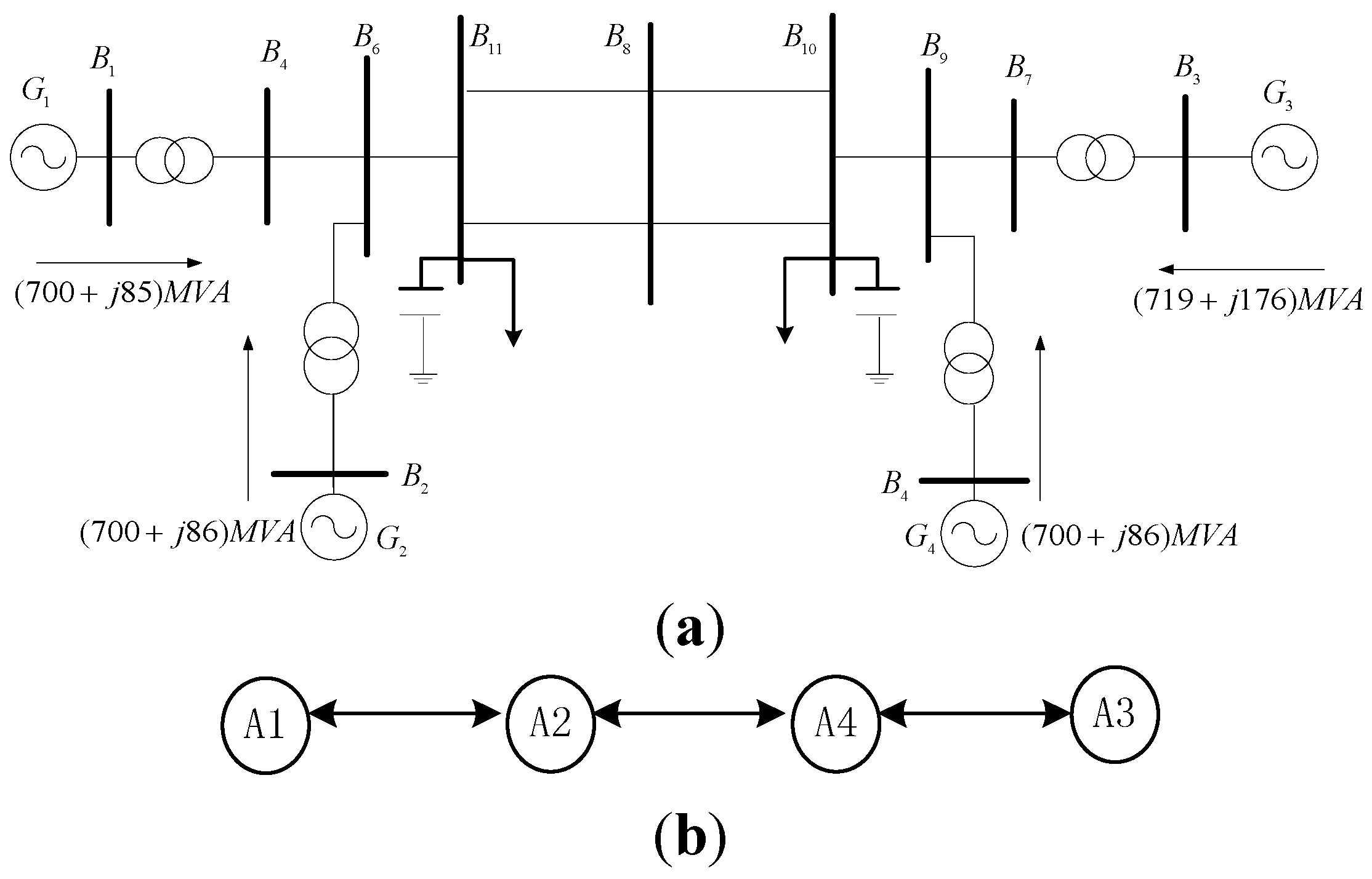
1]. The single line diagram of this system is given in
Figure 1a. It consists of two areas and each area has two equivalent generators. The topology of communication network describing the exchange of information between generator agents is given in
Figure 1b, where agents
A1,
A2,
A3 and
A4 represent generators
G1,
G2,
G3 and
G4. In this network, there are three pairs of agents, namely
A1 and
A2,
A2 and
A4,
A4 and
A3, and the agents in each pair share information with each other.
Figure 1.
Two-area four-machine system. (a) Single line diagram; (b) The topology of communication network.
Figure 1.
Two-area four-machine system. (a) Single line diagram; (b) The topology of communication network.
In our proposed method, generators are coordinated to collectively provide active power for the provision of ancillary frequency regulation service. We select loads in Bus 11 as controllable dynamic loads to perform load characteristic. The proportion of regulating frequency is −3%–3% of the average loads in Bus 11. So Kd = 0.2 is defined to these controllable loads. These loads are controlled in frequency ancillary regulation and power damping.
In the simulation, we use the Power System Toolbox in MATLAB/SIMULINK to test closed-loop responses of controlled nonlinear systems. The simulation step size is 0.001 s. Unlike the proposed analytic model, the simulation model is much more detailed and realistic, including two-axis transient generator model, AC nonlinear power flows, and non-zero line resistances. The simulation would show whether our analytic model and control algorithm is a suitable approximation of the simulation model.
Considering multi-agent system with dynamics (8) and the communication topology given in
Figure 1b, the Laplacian matrix is shown as
. The simulations are conducted for different cases including the small signal disturbances and the short circuit faults. In addition, the system with various parameters for each of the cases are simulated. These simulations aim to check the robustness of distributed controllers obtained with parameter variations. Meanwhile, simulations for the system with different operating conditions are implemented for illustrating the effectiveness of the controller. For all simulations, detailed dynamic responses are considered. For evaluating the performance of the proposed controller, the integral of absolute frequency deviation,
, is selected as a performance index. Nis the total bus node number. The total time internal of
for all simulations are taken as 20 s.
5.1. A Small Signal Disturbance and Stability Analysis
In this case, a small disturbance has occurred in the load demand. The system operates stability before the time of
t = 0 s. At
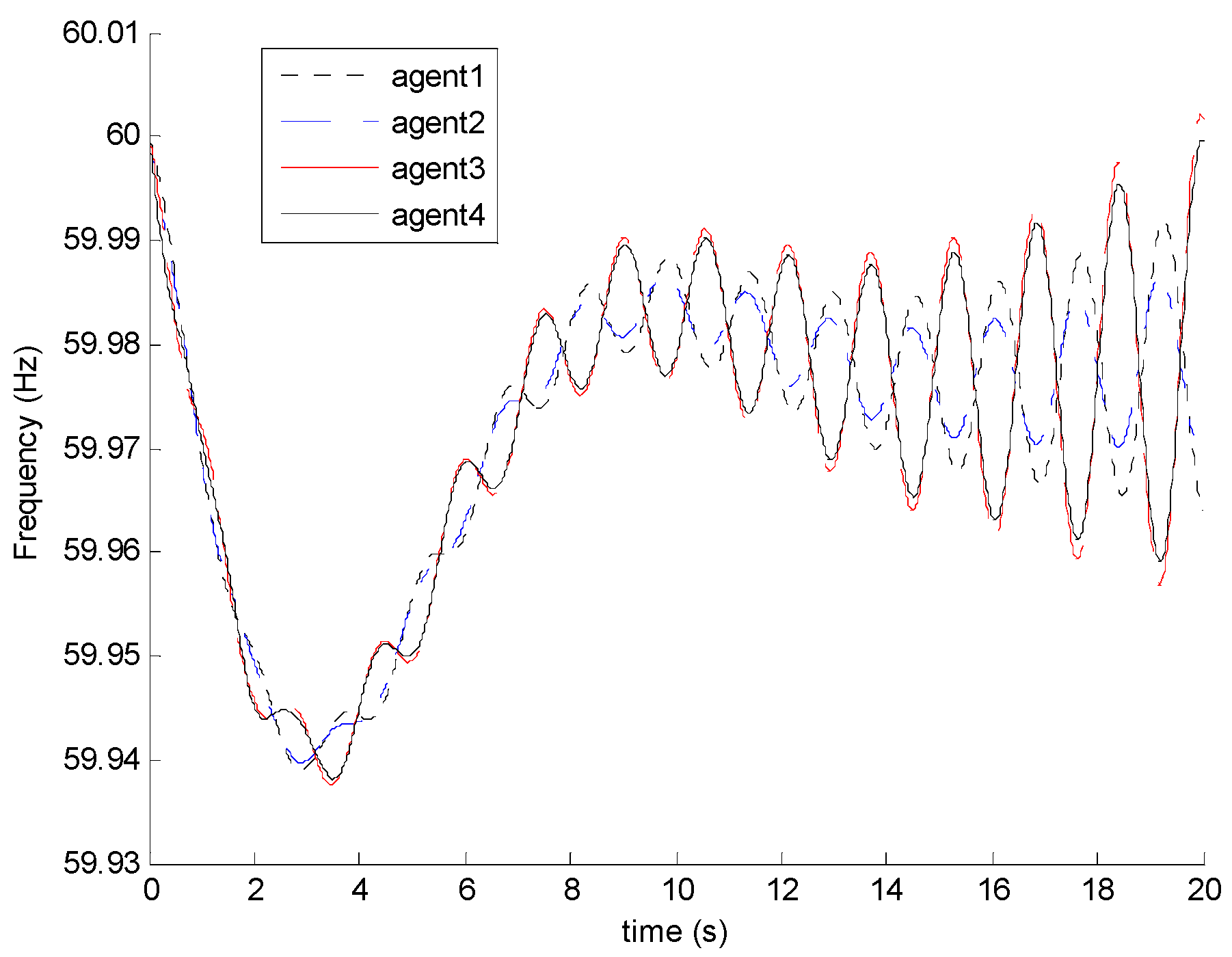
t = 0 s, there is a 1% step increase of the total demand. The frequency curve of the system for the case of without control is given in
Figure 2. It shows that after the instant of load increase, the frequency of the system oscillates and the amplitude increases. Therefore, the system is prone to lose stability when small disturbance happens. In order to guarantee the system’s stability, proper control schemes are required.
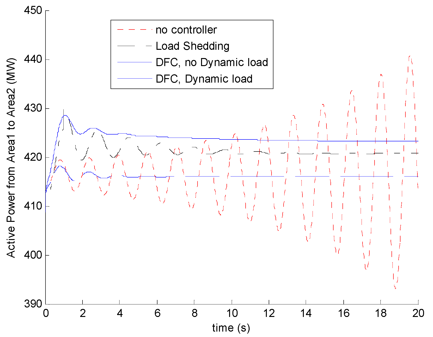
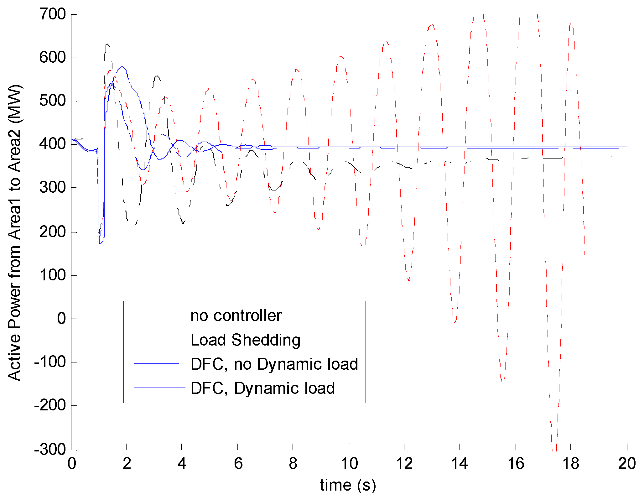
The proposed distributed frequency controllers are tested in the system operation. The power transmitted from area1 to area 2 through the tie-line for the cases of with and without the distributed frequency controller (DFC) are given in
Figure 3. Without the DFC, the power oscillates and the amplitude increases largely. If frequency-sensitive load shedding control strategy is used in Bus 11, the curtailment of the loads is varied according to the frequency drop, which is fluctuated nearly from 16 MW to 10 MW around. The curve shows that the trajectories of the tie-line power continue oscillating at a long time. With the distributed frequency control and no dynamic loads, thepower deviations converge to zero in less than 3 s. Considering DFC and dynamic load characteristics, the power oscillations could be damped faster. It can been seen that the performance of DFCs is more beneficial than load shedding control strategy. It also shows that considering dynamic loads’ characters for frequency regulations, the power transportation and frequency values can increase more than distributed frequency regulations without dynamic loads.
Figure 2.
The frequency deviations without control in a small disturbance.
Figure 2.
The frequency deviations without control in a small disturbance.
Figure 3.
The tie-line active power (MW) versus time (s) with a small disturbance for cases (i) no controller; (ii) load shedding control; (iii) DFC without dynamic loads; (iv) DFC considering dynamic loads.
Figure 3.
The tie-line active power (MW) versus time (s) with a small disturbance for cases (i) no controller; (ii) load shedding control; (iii) DFC without dynamic loads; (iv) DFC considering dynamic loads.
5.2. The Effects of Control Parameters of DFC on Frequency Stability
Previous simulation results indicate that the proposed method is capable to reduce the oscillation. In this section, we will discuss the effects of the control parameters, and , on power system frequency stability.
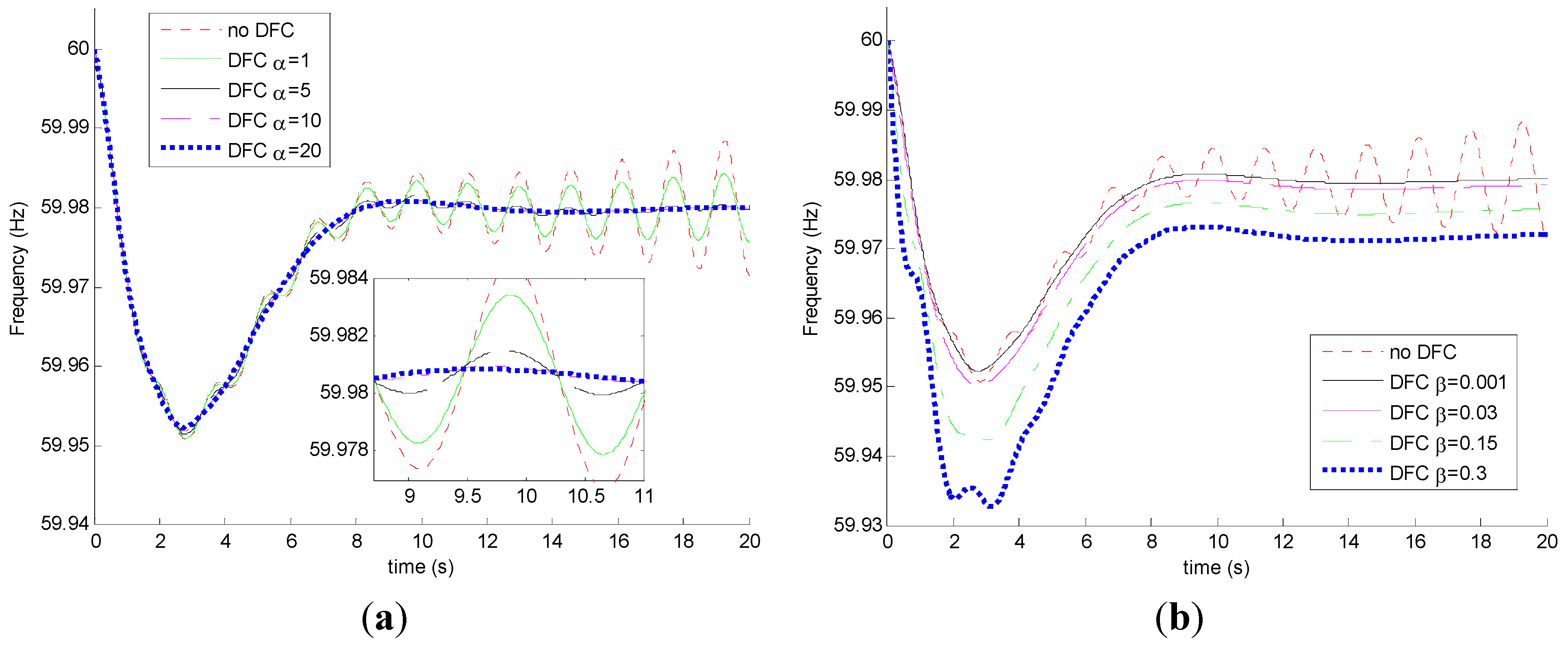
We first set
as zero to observe the effects of parameters
with various values. In fact,
= 0 means that the DFC cannot regulate the agents’ angular acceleration.
Figure 4a gives the frequency curves of system with different controller parameter
. From the figure, we found that the increase of parameter
brings a positive effect on damping frequency oscillations. Obviously, the control with the ability to regulate agents’ angular acceleration would be more effective to damping frequency oscillations. Here we set
= 20 to observe the effects of parameters
with various values. The simulation results are given in
Figure 4b. It shows that the system frequency oscillation is suppressed. In addition, a smaller value of
indicates a better control performance.
Figure 4.
Comparisons of the frequency deviations under different controller parameters in a small disturbance (a) different ( = 0); (b) different ( = 20).
Figure 4.
Comparisons of the frequency deviations under different controller parameters in a small disturbance (a) different ( = 0); (b) different ( = 20).
The performance index of the system with different controller parameter
and
= 0 are calculated. The values of the performance index
J and
are given in
Table 1. In addition, the performance index of the system with different controller parameter
and
= 20 are calculated. In
Table 2, the values of
J gradually increase with the increase of
. This is consistent with the observation that the larger
has a larger
.
Table 1.
The performance index under different controller parameters with the small disturbance ( = 0).
Table 1.
The performance index under different controller parameters with the small disturbance ( = 0).
| Different Controllers | | |
|---|
| NoDFC | 0.0145 | 0.0492 |
| DFC, = 1 | 0.0144 | 0.0491 |
| DFC, = 5 | 0.0143 | 0.0485 |
| DFC, = 10 | 0.0143 | 0.0481 |
| DFC, = 20 | 0.0143 | 0.0477 |
Table 2.
Different performances using different controller parameters with the small disturbance ( = 20).
Table 2.
Different performances using different controller parameters with the small disturbance ( = 20).
| Different Controllers | | |
|---|
| NoDFC | 0.0145 | 0.0492 |
| DFC, = 0.001 | 0.0144 | 0.0477 |
| DFC, = 0.03 | 0.0157 | 0.0497 |
| DFC, = 0.15 | 0.0215 | 0.0577 |
| DFC, = 0.3 | 0.0287 | 0.0673 |
It can be seen that frequency-sensitive loads have shown their frequency regulations in power networks. We also present simulation results below with different kinds of frequency-sensitive loads. Let
Kd denote different kinds of frequency-sensitive loads, different consumption of the frequency-sensitive loads are add on Bus 11. Thus, different kinds of frequency-sensitive load control performance are shown in
Figure 5. In
Figure 5a, the system has no controller, so that the different values of the parameter
Kd cause different undamped oscillations. In
Figure 5b, when the distributed frequency controllers are added, different values of the parameter
Kd can contribute in the power balance and frequency regulation. It shows that these linear frequency-sensitive dynamic loads can rebalance power and resynchronize frequency after a disturbance. If
Kd is larger, the load-side control time is often faster because of little time constants and evident load regulation solutions.
Figure 5.
Comparisons of the frequency deviations under different dynamic load characteristics in a small disturbance. (a) No DFC; (b) with DFC.
Figure 5.
Comparisons of the frequency deviations under different dynamic load characteristics in a small disturbance. (a) No DFC; (b) with DFC.
5.3. A Short-Circuit Fault and Stability Analysis
In order to obtain more information to investigate the distributed controller performance in improving the system stability, transient stability simulations are tested to evaluate the results. A three-phase short-circuit fault is applied at bus8 at t = 1 s, which is cleared after t = 200 ms.
The power transmitted from area1 and area 2 after the fault is observed. As shown in
Figure 6, with the distributed control, less fluctuation appears in the active power from area1 to area 2, and after a relatively short time (around 6 s) the power oscillation disappeared. It also shows that considering frequency-sensitive load regulation in a short circuit fault, the power transportation value could increase more than controllers without dynamic loads to improve system stability.
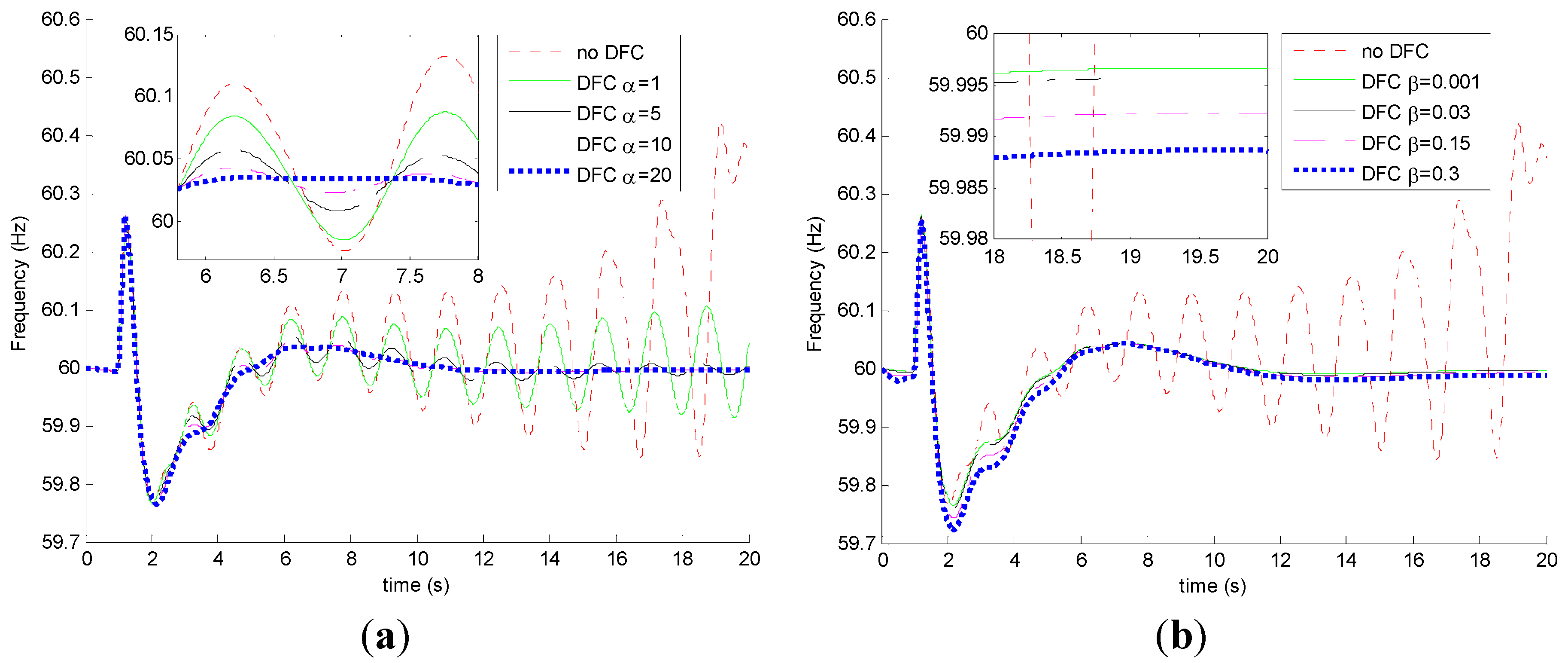
We also observed the frequency oscillation after the short circuit fault cleared. The curves of frequency oscillation of the system for the case with various
and
= 0 are given in
Figure 7a. From the figure, it can be found that the system could keep stable when
is larger than 5. This means that the proposed DFC improves the transient stability if proper
is selected.
In
Figure 7b, the curves of frequency oscillation after the short-circuit fault cleared for case with various
and
= 20 are provided. Observing these curves, we saw that the systems keep stable for all combination patterns of
and
. For different combination patterns of
and
, the performance of the system are quitesimilar, which indicate that parameter
plays a less important role compared to parameter
. If
is larger, the damping control effect is more significant. In addition, a smaller value of
performs a better control effect in the long time.
Figure 6.
The tie-line active power (MW) from area1 to area2 when a three-phase short-circuit fault occurs (i) no DFC; (ii) load shedding control; (iii) DFC without dynamic loads; (iv) DFC considering dynamic loads.
Figure 6.
The tie-line active power (MW) from area1 to area2 when a three-phase short-circuit fault occurs (i) no DFC; (ii) load shedding control; (iii) DFC without dynamic loads; (iv) DFC considering dynamic loads.
Figure 7.
Comparisons of the frequency deviations under different controller parameters with a short-circuit fault (a) different ; (b) different ( = 20).
Figure 7.
Comparisons of the frequency deviations under different controller parameters with a short-circuit fault (a) different ; (b) different ( = 20).
Table 3 and
Table 4 provide the values of the performance indices for the cases of various combination patterns of parameters. These performance indices give the quantitative control evaluation values under different controller parameters.
Table 3.
The performance index under different controller parameters with a short-circuit fault ( = 0).
Table 3.
The performance index under different controller parameters with a short-circuit fault ( = 0).
| Different Controllers | | |
|---|
| NoDFC | 0.3875 | 0.4230 |
| DFC, = 1 | 0.1132 | 0.2591 |
| DFC, = 5 | 0.0771 | 0.2600 |
| DFC, = 10 | 0.0765 | 0.2607 |
| DFC, = 20 | 0.0799 | 0.2616 |
Table 4.
Theperformance index using different controller parameters with a short-circuit fault disturbance ( = 20).
Table 4.
Theperformance index using different controller parameters with a short-circuit fault disturbance ( = 20).
| Different Controllers | | |
|---|
| NoDFC | 0.3875 | 0.4230 |
| DFC, = 0.001 | 0.0866 | 0.2645 |
| DFC, = 0.03 | 0.0829 | 0.2602 |
| DFC, = 0.15 | 0.0949 | 0.2558 |
| DFC, = 0.3 | 0.1096 | 0.2730 |
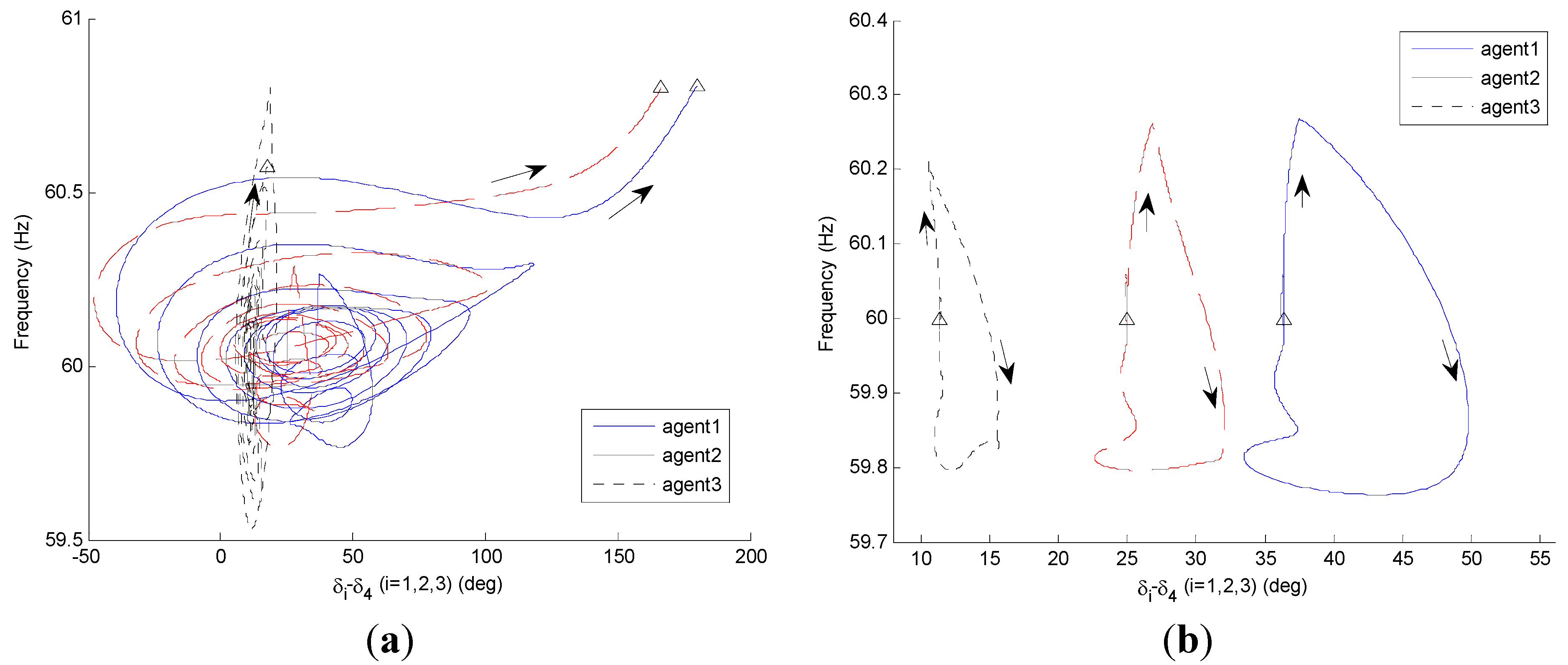
Figure 8a shows the phase plane diagram of frequency oscillation for the case without DFC. The agents’ frequencies oscillate and finally the system turns into being in an unstable state. Then, we install DFC to each of these agents. The phase plane diagram of frequency oscillation is given in
Figure 8b. In the figure, the state of each agent deviates from its original state, and after a certain time, goes back to the original state. This means that the DFC can keep the frequencies stable in the case of short-circuit fault occurred.
Figure 8.
The phase plane diagram under (a) no DFC; (b) DFC with a short-circuit fault disturbance.
Figure 8.
The phase plane diagram under (a) no DFC; (b) DFC with a short-circuit fault disturbance.
In summary, it can be concluded that the distributed frequency control can provide a guarantee of more reliable and stable power supply in the power system. The controller improves both the steady-state and transient performance of frequency. Compared with the central frequency control, the distributed frequency control method is more secure and efficient.


