
Simplified Minimum Copper Loss Remedial Control of a Five-Phase Fault-Tolerant Permanent-Magnet Vernier Machine under Short-Circuit Fault

Abstract
:1. Introduction
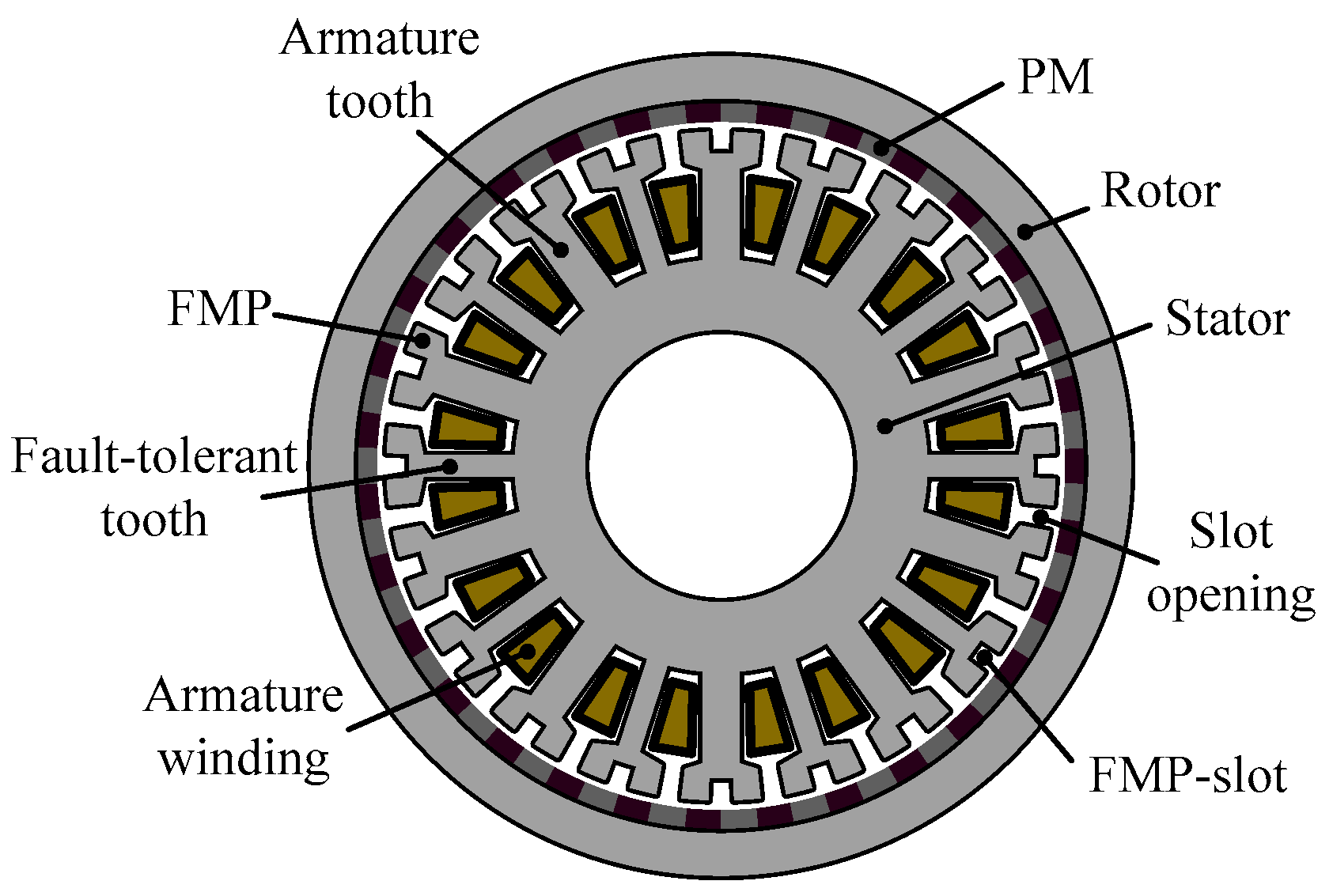
2. Topology and Feature
3. Open-Circuit Fault-Tolerant Control
4. Short-Circuit Fault-Tolerant Control
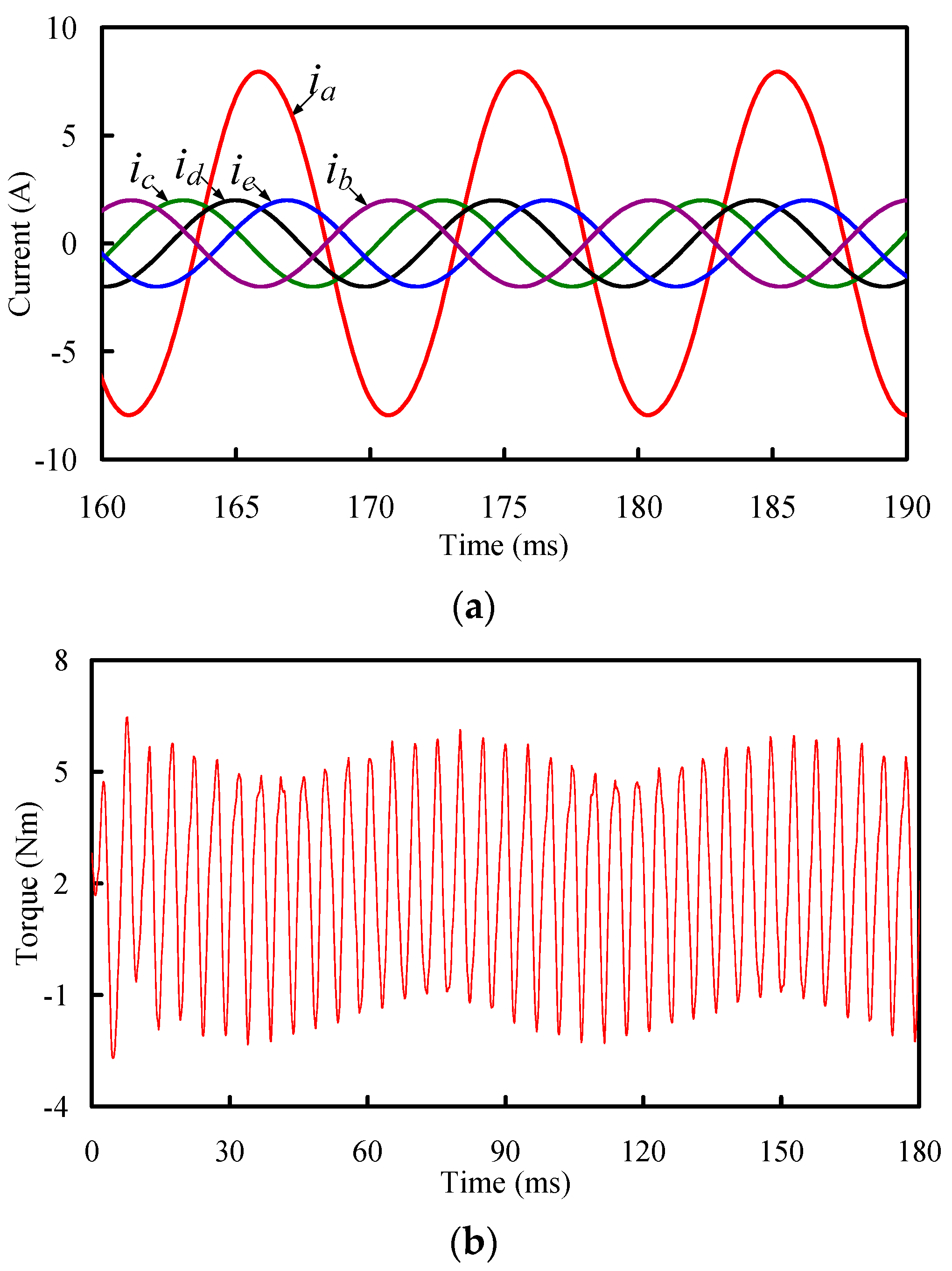
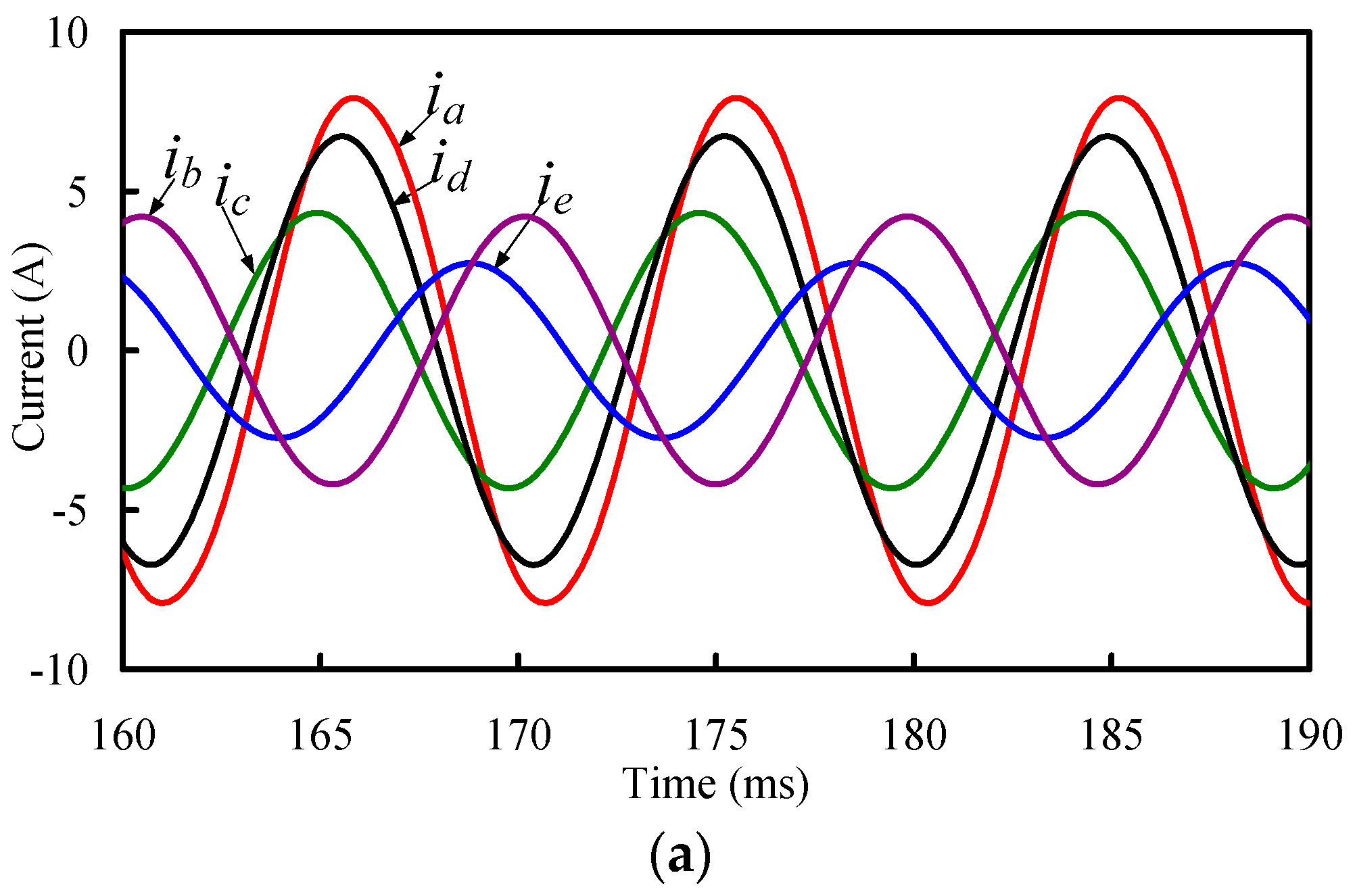
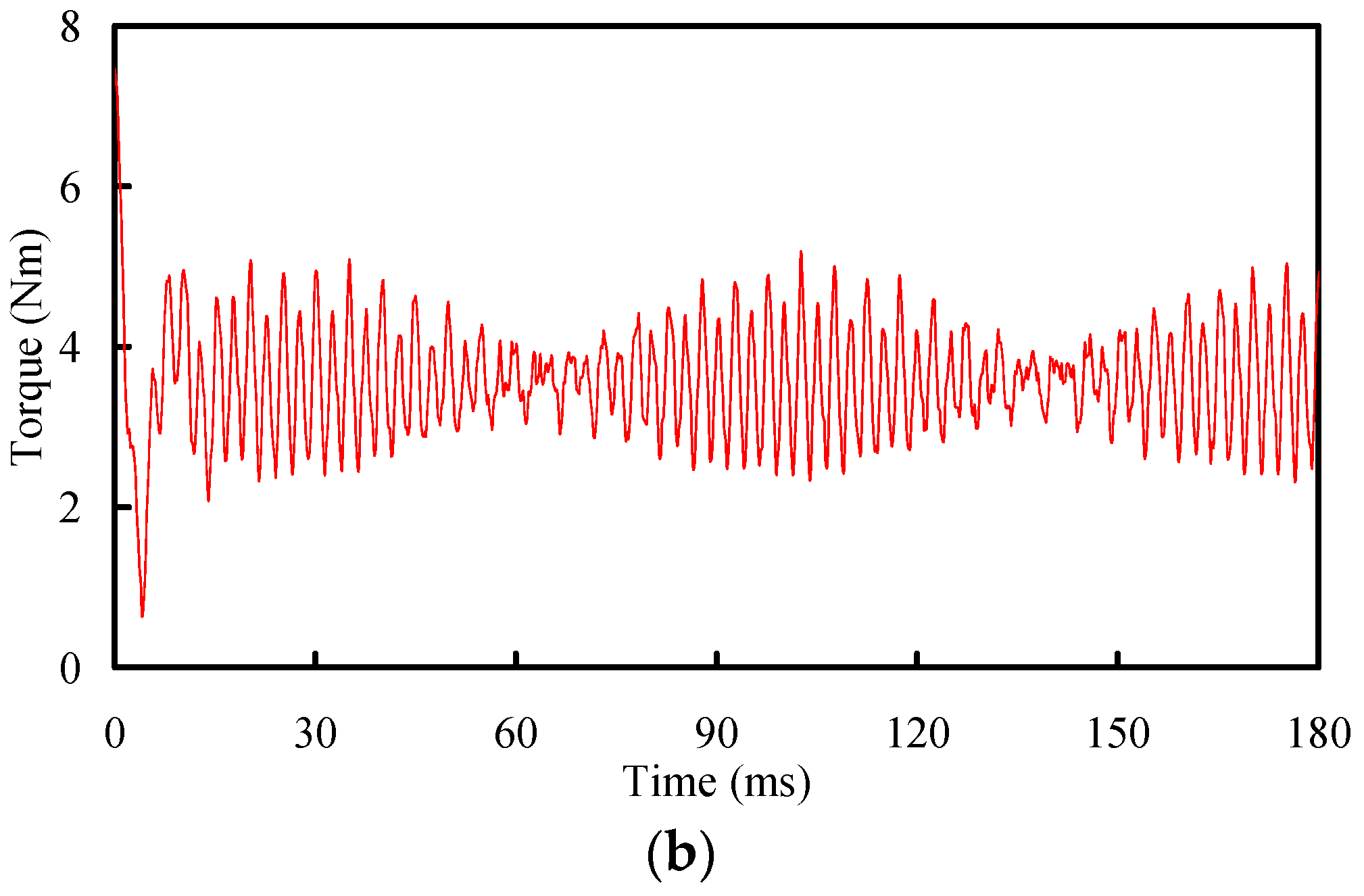
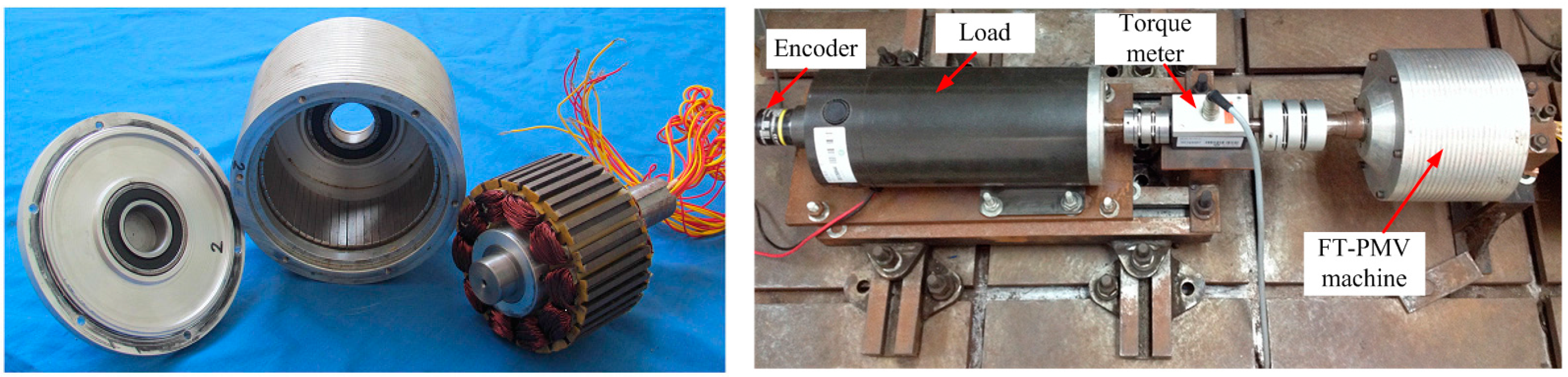
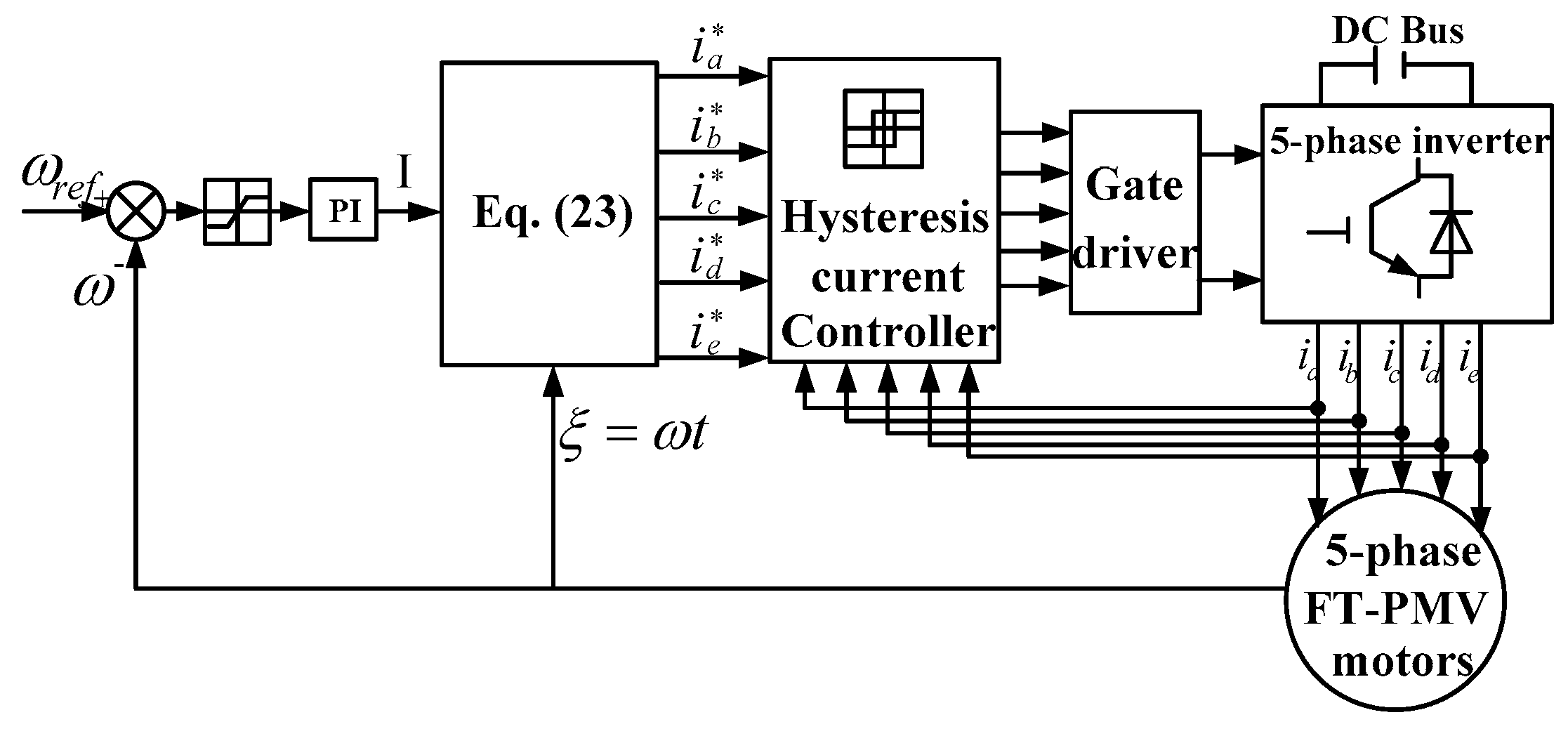
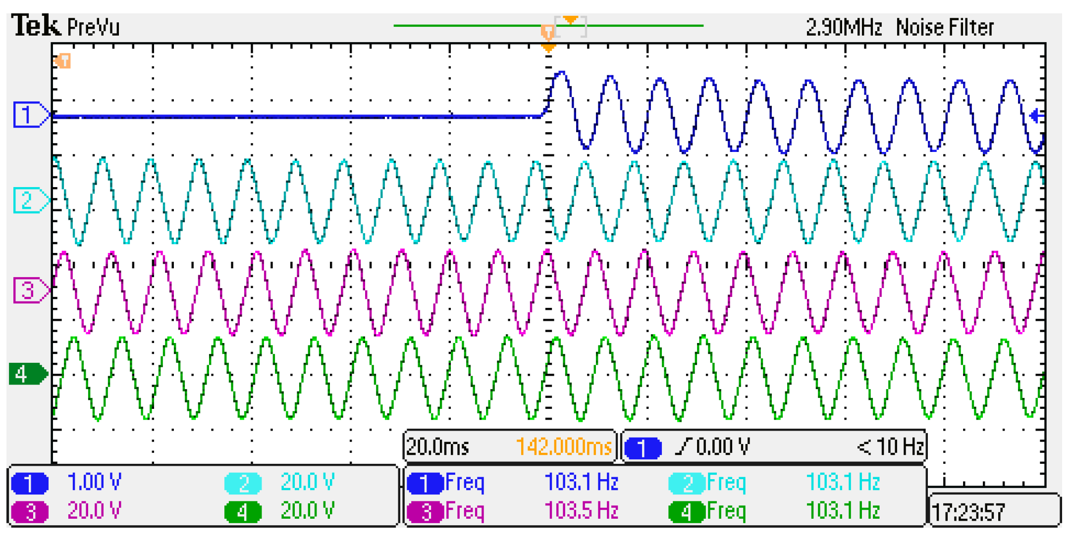
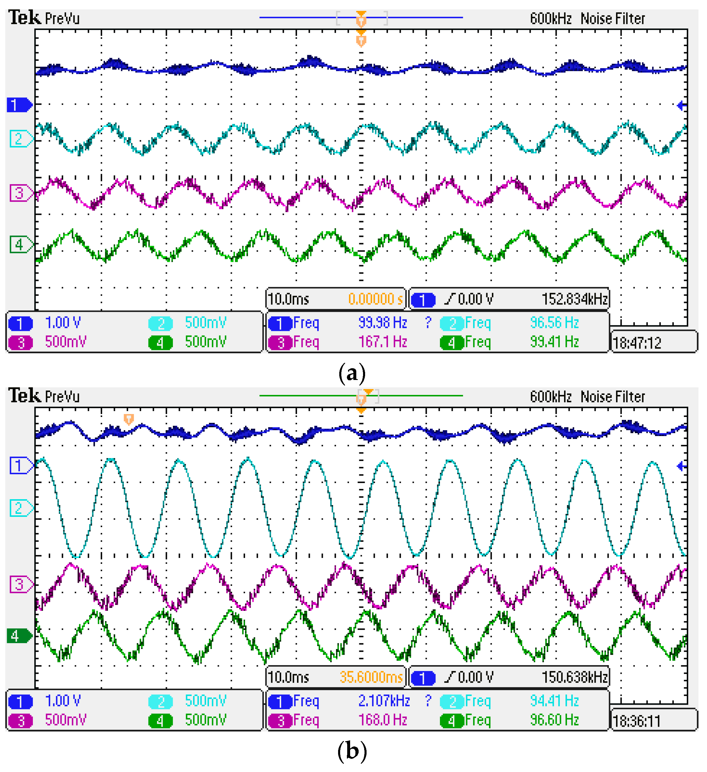
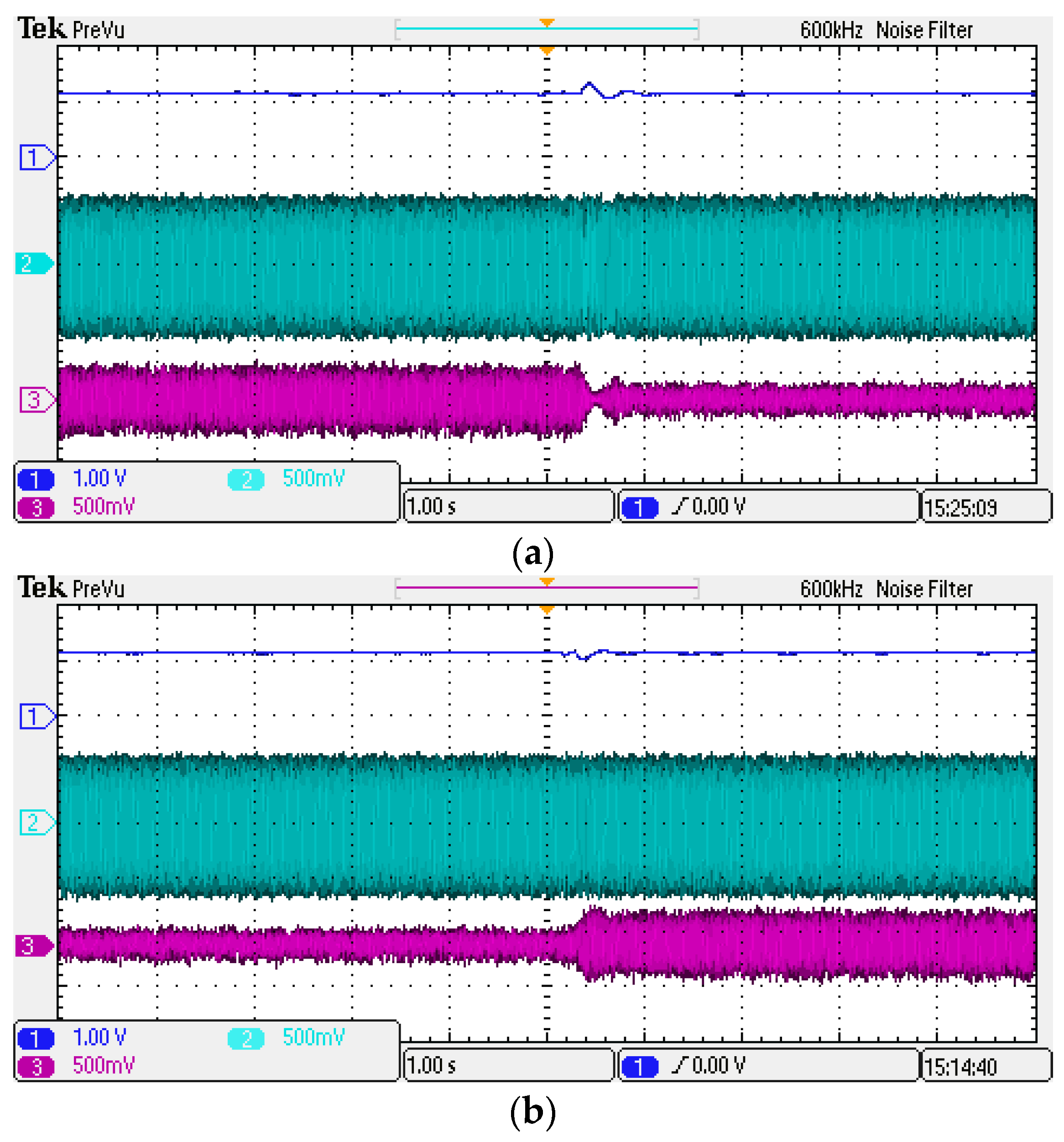
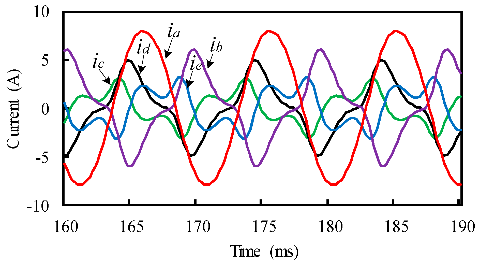
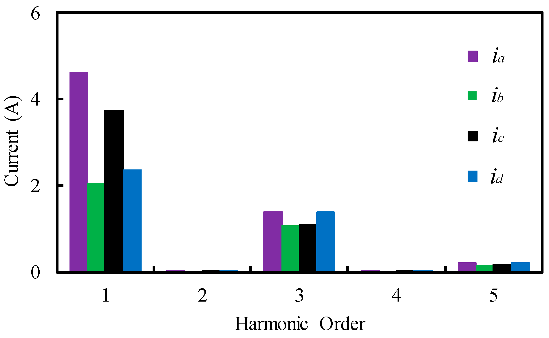
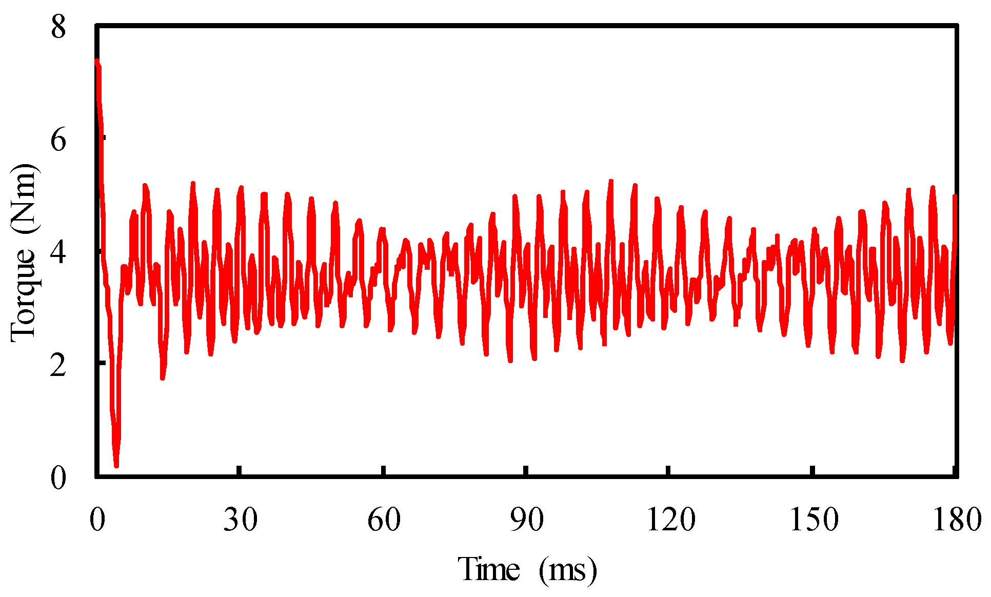
5. Validation
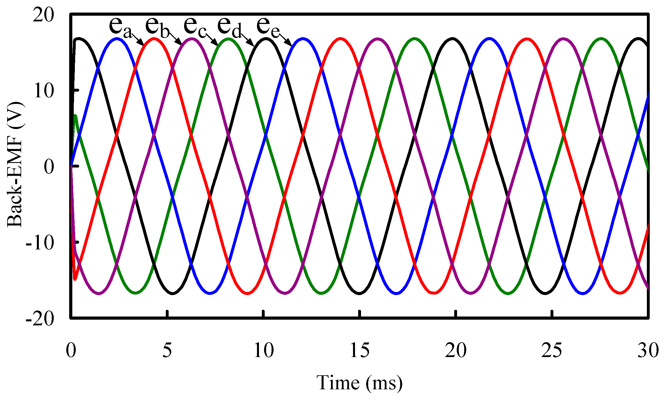
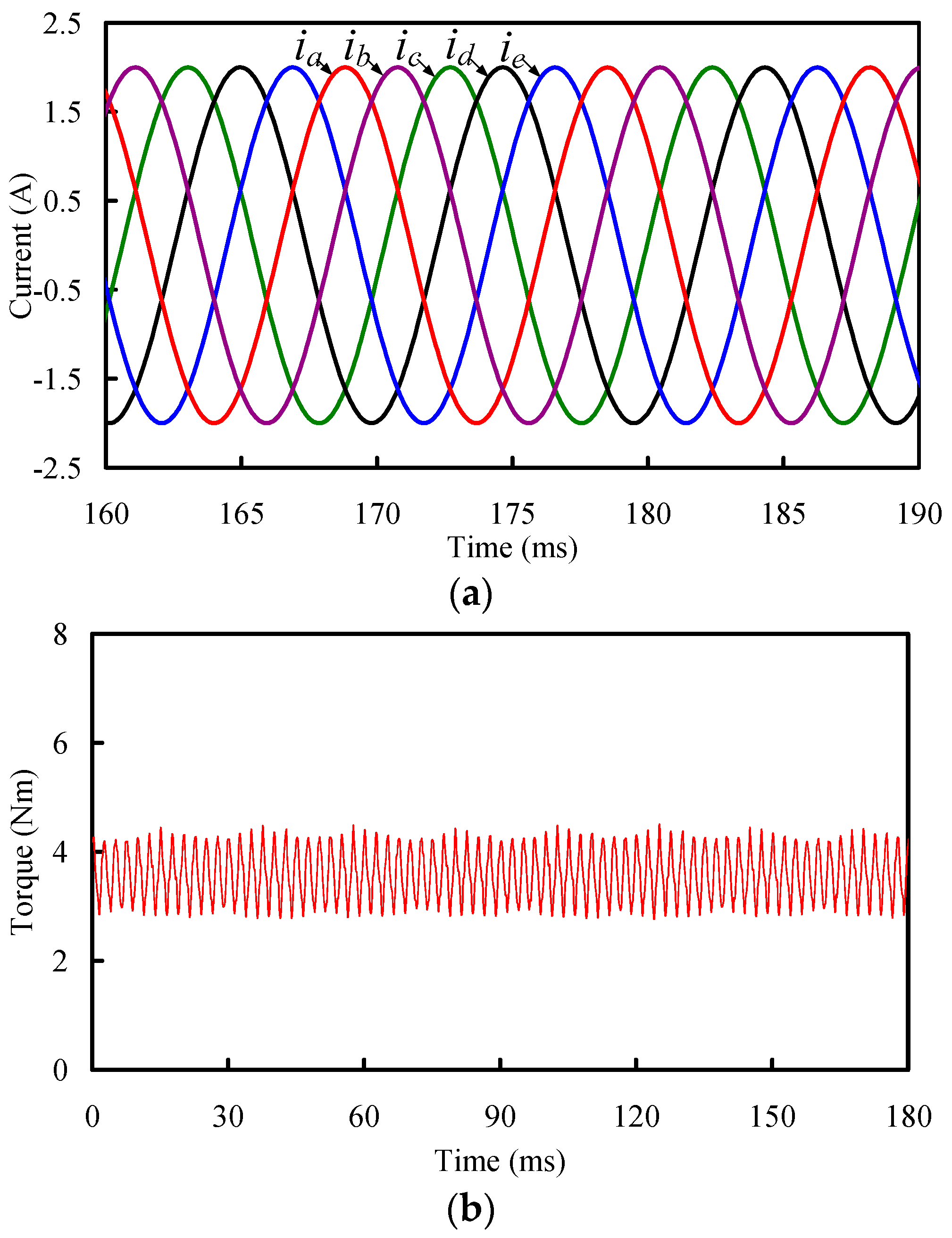
5.1. Simulation
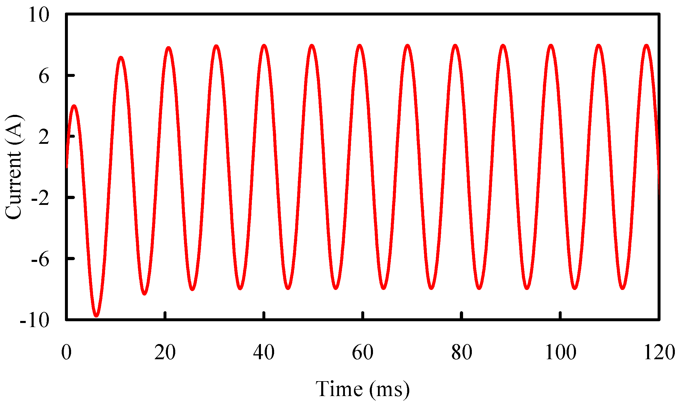
5.2. Experiment
6. Comparisons and Discussion
7. Conclusions
Acknowledgments
Author Contributions
Conflicts of Interest
References
- Cheng, M.; Sun, L.; Buja, G.; Song, L. Advanced electrical machines and machine-based systems for electric and hybrid vehicles. Energies 2015, 8, 9541–9564. [Google Scholar] [CrossRef]
- Jiang, X.; Huang, W.; Cao, R.; Hao, Z.; Li, J. Analysis of a dual-winding fault-tolerant permanent magnet machine drive for aerospace applications. IEEE Trans. Magn. 2015, 51, 8114704. [Google Scholar] [CrossRef]
- Zhao, J.; Gao, X.; Li, B.; Liu, X.; Guan, X. Open-phase fault tolerance techniques of five-phase dual-rotor permanent magnet synchronous motor. Energies 2015, 8, 12810–12838. [Google Scholar] [CrossRef]
- Bianchi, N.; Bolognani, S.; Zigliotto, M.; Zordan, M. Innovative remedial strategies for inverter faults in IPM synchronous motor drives. IEEE Trans. Energy Convers. 2003, 18, 306–314. [Google Scholar] [CrossRef]
- Mendes, A.M.S.; Cardoso, A.J.M. Fault-tolerant operating strategies applied to three-phase induction-motor drives. IEEE Trans. Ind. Electron. 2006, 53, 1807–1817. [Google Scholar] [CrossRef]
- Ding, W.; Hu, Y.; Wu, L. Investigation and experimental test of fault-tolerant operation of a mutually coupled dual three-phase SRM drive under faulty conditions. IEEE Trans. Power Electron. 2015, 30, 6857–6872. [Google Scholar] [CrossRef]
- Wang, Z.; Chen, J.; Cheng, M.; Zheng, Y. Fault tolerant control of paralleled voltage-source inverters fed PMSM drives. IEEE Trans. Ind. Electron. 2015, 62, 4749–4760. [Google Scholar] [CrossRef]
- Levi, E.; Bojoi, R.; Profumo, F.; Toliyat, H.; Williamson, S. Multiphase induction motor drives—A technology status review. IET Electr. Power Appl. 2007, 1, 489–516. [Google Scholar] [CrossRef]
- Baek, S.K.; Shin, H.U.; Kang, S.Y.; Park, C.S.; Lee, K.B. Open fault detection and tolerant control for a five phase inverter driving system. Energies 2016, 9, 355. [Google Scholar] [CrossRef]
- Wang, D.; Liu, C.; Li, G. An optimal integrated control scheme for permanent magnet synchronous generator-based wind turbines under asymmetrical grid fault conditions. Energies 2016, 9, 307. [Google Scholar] [CrossRef]
- Duran, M.J.; Barrero, F. Recent advances in the design, modeling, and control of multiphase machines. IEEE Trans. Ind. Electron. 2016, 63, 459–468. [Google Scholar] [CrossRef]
- Mohammadpour, A.; Parsa, L. A unified fault-tolerant current control approach for five-phase PM motors with trapezoidal back EMF under different stator winding connections. IEEE Trans. Power Electron. 2013, 28, 3517–3527. [Google Scholar] [CrossRef]
- Prieto, B.; Martínez-Iturralde, M.; Fontán, L.; Elosegui, I. Fault-tolerant permanent magnet synchronous machine-phase, pole and slot number selection criterion based on inductance calculation. IET Electr. Power Appl. 2015, 9, 138–145. [Google Scholar] [CrossRef]
- Liu, G.; Qu, L.; Zhao, W.; Chen, Q.; Xie, Y. Comparison of two SVPWM control strategies for give-phase fault-tolerant permanent-magnet motor. IEEE Trans. Power Electron. 2016, 31, 6621–6630. [Google Scholar] [CrossRef]
- Zhao, W.; Cheng, M.; Hua, W.; Jia, H.; Cao, R. Back-EMF harmonic analysis and fault-tolerant control of flux-switching permanent-magnet machine with redundancy. IEEE Trans. Ind. Electron. 2011, 58, 1926–1935. [Google Scholar] [CrossRef]
- Chen, Q.; Liu, G.; Zhao, W.; Sun, L.; Shao, M.; Liu, Z. Design and comparison of two fault-tolerant interior-permanent-magnet motors. IEEE Trans. Ind. Electron. 2014, 61, 6615–6623. [Google Scholar] [CrossRef]
- Liu, G.; Yang, J.; Zhao, W.; Ji, J.; Chen, Q.; Gong, W. Design and analysis of a new fault-tolerant permanent-magnet vernier machine for electric vehicles. IEEE Trans. Magn. 2012, 48, 4176–4179. [Google Scholar] [CrossRef]
- Dwari, S.; Parsa, L. An optimal control technique for multiphase PM machines under open-circuit faults. IEEE Trans. Ind. Electron. 2008, 55, 1988–1995. [Google Scholar] [CrossRef]
- Dwari, S.; Parsa, L. Fault-tolerant control of five-phase permanent-magnet motors with trapezoidal back EMF. IEEE Trans. Ind. Electron. 2011, 58, 476–485. [Google Scholar] [CrossRef]
- Tani, A.; Mengoni, M.; Zarri, L.; Serra, G.; Casadei, D. Control of multiphase induction motors with an odd number of phases under open-circuit phase faults. IEEE Trans. Power Electron. 2012, 27, 565–577. [Google Scholar] [CrossRef]
- Kestelyn, X.; Semail, E. A vectorial approach for generation of optimal current references for multiphase permanent magnet synchronous machines in real time. IEEE Trans. Ind. Electron. 2011, 58, 5057–5065. [Google Scholar] [CrossRef] [Green Version]
- Zhao, W.; Cheng, M.; Chau, K.T.; Cao, R.; Ji, J. Remedial injected-harmonic-current operation of redundant flux-switching permanent-magnet motor drives. IEEE Trans. Ind. Electron. 2013, 60, 151–159. [Google Scholar] [CrossRef] [Green Version]
- Mohammadpour, A.; Sadeghi, S.; Parsa, L. A generalized fault-tolerant control strategy for five-phase PM motor drives considering star, pentagon, and pentacle connections of stator windings. IEEE Trans. Ind. Electron. 2014, 61, 63–75. [Google Scholar] [CrossRef]
- Salehifar, M.; Salehi Arashloo, R.; Moreno-Eguilaz, M.; Sala, V.; Romeral, L. Observer-based open transistor fault diagnosis and fault-tolerant control of five-phase permanent magnet motor drive for application in electric vehicles. IET Power Electron. 2015, 8, 76–87. [Google Scholar] [CrossRef]
- Bianchi, N.; Bolognani, S.; Pre, M. Strategies for the fault-tolerant current control of a five-phase permanent-magnet motor. IEEE Trans. Ind. Appl. 2007, 43, 960–970. [Google Scholar] [CrossRef]
- Mohammadpour, A.; Mishra, S.; Parsa, L. Fault-tolerant operation of multiphase permanent-magnet machines using iterative learning control. IEEE J. Emerg. Sel. Top. Power Electron. 2014, 2, 201–211. [Google Scholar] [CrossRef]
- Mohammadpour, A.; Parsa, L. Post-fault control technique for multi-phase PM motor drives under short-circuit faults. In Proceedings of the 2013 Twenty-Eighth Annual IEEE Applied Power Electronics Conference and Exposition (APEC), Long Beach, CA, USA, 17–21 March 2013.
- Mohammadpour, A.; Parsa, L. Global fault-tolerant control technique for multi-phase permanent-magnet machines. IEEE Trans. Ind. Appl. 2015, 51, 178–186. [Google Scholar] [CrossRef]
- Sen, B.; Wang, J. Stationary frame fault-tolerant current control of polyphase permanent-magnet machines under open-circuit and short-circuit faults. IEEE Trans. Power Electron. 2016, 31, 4684–4696. [Google Scholar]
- Sedrine, E.B.; Ojeda, J.; Gabsi, M.; Slama-Belkhodja, I. Fault-tolerant control using the GA optimization considering the reluctance torque of a five-phase flux switching machine. IEEE Trans. Energy Convers. 2015, 30, 927–938. [Google Scholar] [CrossRef]
- Nguyen, N.; Meinguet, F.; Semail, E.; Kestelyn, X. Fault-tolerant operation of an open-end winding five-phase PMSM drive with short-circuit inverter fault. IEEE Trans. Ind. Electron. 2016, 63, 595–605. [Google Scholar] [CrossRef]
- Jen-Ren, F.; Lipo, T.A. Disturbance-free operation of a multiphase current-regulated motor drive with an opened phase. IEEE Trans. Ind. Appl. 1994, 30, 1267–1274. [Google Scholar] [CrossRef]
- Atallah, K.; Wang, J.; Howe, D. Torque-ripple minimization in modular permanent-magnet brushless machines. IEEE Trans. Ind. Appl. 2003, 39, 1689–1695. [Google Scholar] [CrossRef]


| Rated output power (kW) | 1.8 |
| Rated current (A) | 10 |
| Rated speed (rpm) | 200 |
| Number of phases | 5 |
| Number of stator slots | 20 |
| Number of rotor pole pairs | 31 |
| Number of FMPs | 40 |
| Rated voltage (V) | 70 |
| Current density (A/mm2) | 6.6 |
| Outside stator radius (mm) | 60 |
| Outside rotor radius (mm) | 70 |
| Stack length (mm) | 60 |
| Air-gap length (mm) | 0.5 |
| PM thickness (mm) | 3.2 |
| Fault-tolerant tooth length (mm) | 1.9 |
| Armature tooth length (mm) | 3.3 |
| Number of stator turns per coil | 48 |
| Torque | Normal | Fault | Remedial |
|---|---|---|---|
| Maximum torque (Nm) | 4.5 | 6.5 | 5.0 |
| Minimum torque (Nm) | 2.7 | −2.7 | 2.3 |
| Torque ripple (%) | 24.5 | 242.1 | 37.0 |
© 2016 by the authors; licensee MDPI, Basel, Switzerland. This article is an open access article distributed under the terms and conditions of the Creative Commons Attribution (CC-BY) license (http://creativecommons.org/licenses/by/4.0/).
Share and Cite
Gu, C.; Zhao, W.; Zhang, B. Simplified Minimum Copper Loss Remedial Control of a Five-Phase Fault-Tolerant Permanent-Magnet Vernier Machine under Short-Circuit Fault. Energies 2016, 9, 860. https://doi.org/10.3390/en9110860
Gu C, Zhao W, Zhang B. Simplified Minimum Copper Loss Remedial Control of a Five-Phase Fault-Tolerant Permanent-Magnet Vernier Machine under Short-Circuit Fault. Energies. 2016; 9(11):860. https://doi.org/10.3390/en9110860
Chicago/Turabian StyleGu, Chenyu, Wenxiang Zhao, and Bufeng Zhang. 2016. "Simplified Minimum Copper Loss Remedial Control of a Five-Phase Fault-Tolerant Permanent-Magnet Vernier Machine under Short-Circuit Fault" Energies 9, no. 11: 860. https://doi.org/10.3390/en9110860