Article

Design and Optimization of the Slide Guide System of Hydraulic Press Based on Energy Loss Analysis

1
School of Mechanical and Automotive Engineering, Hefei University of Technology, Hefei 230009, China
2
Environmental and Ecological Engineering, Purdue University, West Lafayette, IN 47907, USA
*
Author to whom correspondence should be addressed.
Energies 2016, 9(6), 434; https://doi.org/10.3390/en9060434
Submission received: 7 April 2016 / Revised: 21 May 2016 / Accepted: 31 May 2016 / Published: 3 June 2016
(This article belongs to the Special Issue Energy Saving Design for Manufacturing Process, Product, and System)

Abstract

:
The clearances in the slide guide system of a hydraulic press are one of the significant factors affecting its accuracy. These clearances also affect the energy consumption of the press. An energy loss model that considers the oil leaks and friction associated with these clearances was proposed, and the size of clearances was optimized based on the model. The maximum allowable eccentric load and the energy loss on the wedge clearance condition were calculated to ensure the slide and guide pillars function properly. The stiffness of pillars and wear of guide rails were checked under an eccentric load condition. A case for rapid sheet metal forming with a 20 MN hydraulic press was examined. For this case, the optimum fit clearances were found to be approximately 0.4 mm. The energy loss under an eccentric load condition was increased by approximately 83% compared to a non-eccentric load condition. The pillars were optimized by reducing excessive stiffness, which served to decrease the pillar weight by nearly 20%.

1. Introduction

It is often said that manufacturing is the engine for economic development; in many countries, manufacturing also represents the largest energy end-use. In 2010, China’s manufacturing sector accounted for about 60% of the total energy consumption [1]. A large portion of the energy consumption in this sector is associated with production processes, which is attributable to production equipment. Hydraulic presses are a mainstay in metal forming processes, owing to their ability to deliver high forming pressures; however, they are also large energy consumers [2,3]. In 2013, China produced about 2 million metal forming presses. If the average power demand of one of these presses is 40 kWh, more than 280 billion kWh will be consumed per year, which is comparable to the total energy consumed by Spain in 2014 [4]. Over the past several decades, much research has been performed on the efficiency and energy consumption of hydraulic presses [5,6]. This has shown that the slide, as the principal element of the press system, consumes most of the energy in the forming process. The slide guide system has a tremendous effect on the kinematic behavior of the slide and the associated forming accuracy, and affects the oil leakage from clearances associated with the working cylinder, wear of the guide rails [7], and life of the forming dies.
The slide guide system of a hydraulic press is composed of a slide and four guide pillars. The orientation of the slide, and its function, depends on the fit between the guide rails on pillars and the adjustable guide plates on the slide. The clearances are the gaps between the flat surfaces of the guide rails and the adjustable guide plates, as shown in Figure 1. An oil film exists within the clearances that separate the surfaces of rails on pillars and the adjustment plates on the slide. This film is used to avoid metal-on-metal rubbing. As the lubricating oil film migrates or leaks from the clearance gaps, a reservoir replaces the lost fluid. A small clearance means less leakage, but it also means larger friction. A large gap serves to reduce the friction but may compromise forming accuracy and produce more oil losses. It is evident the total energy is dependent on the sizes of the clearances, and that it is important to consider the fit of adjustable guide plates on the slide and the guide rails on pillars from an overall systems perspective.
When a hydraulic press is used to deform a workpiece, the asymmetric geometry of the workpiece, positioning errors, and uneven heating of dies may lead to an asymmetric resistance force that acts on the slide. This eccentric load produces a complex stress state [8]. Much research has been performed to analyze and solve this problem. Osakada et al. indicated that crank presses with two connecting rods could increase the power and maintain parallelism of the slide under an off-center load [9]. Wagener et al. focused on determining the angular deflection, lateral offset, and angular spring constant of the die guidance system under central and eccentric loading. They reported that heel blocks with brass plates produce optimal improvement with regard to die and slide tilting and lateral offset, and a combination of heel block guides and pillar guides produces only a small increase in angular stiffness [10]. Peipei and Haibin put forward the concept and operating principle for a moment leveling and position control system to find the required correcting moment [11]. Jimma, Sekine, and Tozawa proposed an analytical method to select a suitable press for a given die set and eccentric load [12].
As expected, the stiffness of the principal elements in a hydraulic press plays an important role in realizing forming accuracy. Finite element simulation has been widely used in the design, analysis, and optimization of presses (Chval et al. [13], Socrate et al. [14], and Zhao et al. [15]). Such efforts have been employed to predict the maximum safe stress beyond which defects and wear will occur, the optimal cross-sectional area of structural elements, etc. However, the stress distributions from simulations do not always compare well with the results of experiments. Other methods have been used to analyze the stiffness of presses. For example, Arentoft et al. proposed a new procedure for measuring press stiffness, including separated horizontal and vertical loading of the press frame. The load can be eccentrically positioned for measuring rotational stiffness [16].
The impact of eccentric loads and the stiffness of components has been investigated with respect to the forming accuracy of hydraulic presses. However, it is still unknown how the clearances and guide geometry of the system affect the stiffness and accuracy of a hydraulic press. No research literature was found that discusses how the clearances and guide geometry affect the press energy consumption. Almost always, the clearances and guide length are determined based on experience [17,18]. This paper aims to optimize the clearances and guide length for a slide guide system; it is envisioned that this solution will provide an excellent reference for the design of clearances and the adjustment of hydraulic presses.
The contents of this paper consists of four sections. The energy loss caused by the lubricating oil leakage and friction between the slide and guides (separated by clearances) under the conditions of centered and eccentric loading is analyzed in Section 2. Then, the maximum allowable lateral force is studied, and the stiffness of the pillars and wear of guide rails are examined under an eccentric load condition in Section 3. A case study is presented in Section 4. Finally, the paper presents a summary and conclusions.

2. Energy Loss Analysis in the Slide Guide System

During a metal forming process, the slide moves up and down, with its position constrained by the guides affixed to the pillars. Lubrication in the slide guide system is provided by an oil film that fills the clearance gaps between the guide rails and the adjustable guide plates. The lubricating oil in the clearance gaps ensures that relative motion between the slide and pillars occurs without metal on metal contact. A consequence of the relative motion of the slide and the clearance gaps is that the lubricating oil will leak from the system (oil is made up from a reservoir). Frictional power losses are associated with the interfaces between the slide and the guide rails. Since lost oil in the system must be replaced, this will also consume power [19].

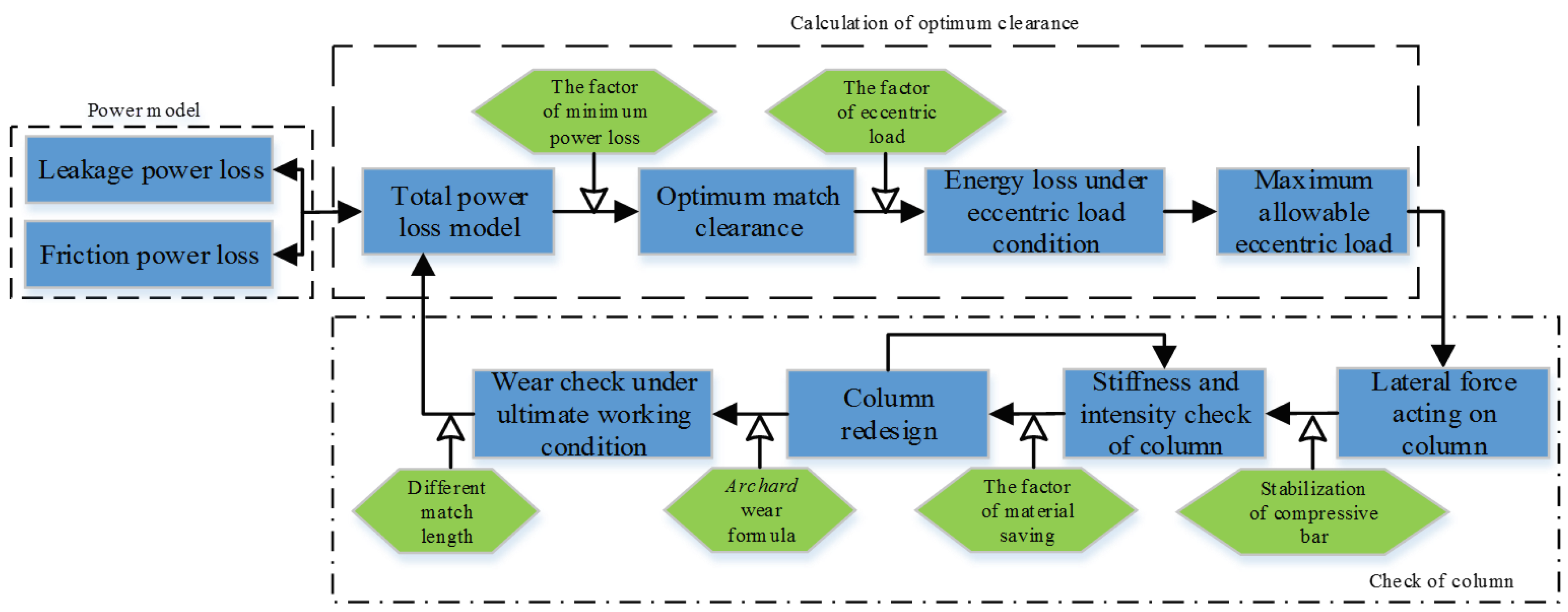
2.1. Energy Loss Model

Assuming that the guide surfaces are parallel to the plane of adjustable guide plates under central loading as shown in Figure 2, the amount of oil leakage q for a single clearance gap can be described with Equation (1) [20]:
q = b δ 3 Δ p 12 μ L b δ v 2
where δ is size of the clearance, Δp is the differential oil pressure between the two ends of clearance (produced by oil leakage), L is the length of adjustable guide plate, b is the width, μ is the dynamic viscosity of hydraulic oil, and v is the velocity of slide.
Then, the leaking power loss Pq is given by Equation (2):
P q = Δ p q = Δ p b ( δ 3 Δ p 12   μ L δ v 2 )
At the location of z = δ, the friction force in the parallel clearances is:
F f = τ A = μ d u d z | z = δ A = b L ( Δ p δ 2 L + μ v δ )
where τ is the shear stress of the oil at the moving surface. A is the contact area which is equal to the area of adjustable guide plate. The energy loss per unit time caused by friction, namely the friction power loss Pf, is given by Equation (4):
P f = F f v = v b L ( Δ p δ 2 L + μ v δ )
The total power loss is given by:
P T = P q + P f = b ( Δ p 2 δ 3 12   μ L + μ L v 2 δ )
From the equations above, it is evident that the power loss due to oil leakage increases with increasing δ, but the power loss due to friction decreases with increasing δ. Therefore, there must be an optimum clearance δ that minimizes the total power loss. This is given as follows:
d P d δ = 0 δ = 2 μ L v Δ p
Since the relative velocity v, between the slide and guide pillars changes during the forming process, the energy loss for a working cycle (slide moving down to execute the process and then returning to the starting position) of time T is given by Equation (7):
E = 0 T 16 P T d t = 4 3 b Δ p 2 δ 3 T μ L + 16 b μ L δ 0 t v ( t ) 2 d t

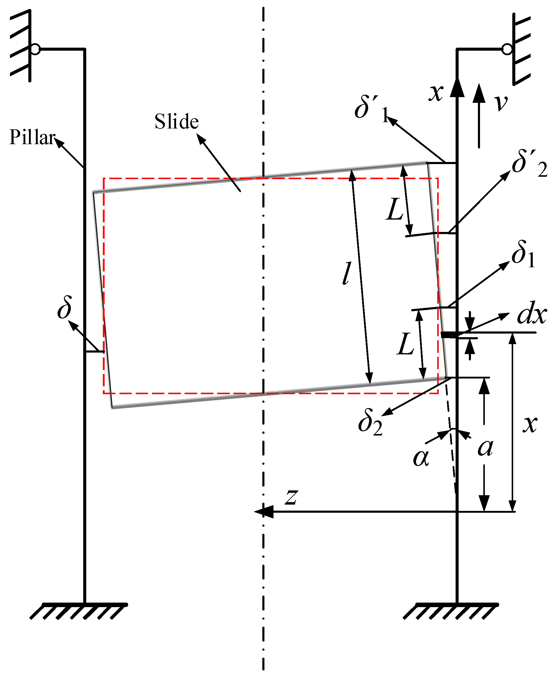
2.2. Energy Loss Considering Eccentric Load

The parallel oil-film clearances turn into wedge oil-film clearances in the slide guide systems under an eccentric load, as shown in Figure 2, in which the pillar moves with velocity v and the slide is regarded as stationary. The amount of oil leakage in the wedge clearance may be expressed using Equation (8) [20]:
q = b δ 1 δ 2 δ 1 + δ 2 ( δ 1 δ 2 6 μ L Δ p + v )
Since the tilt angle α caused by an eccentric load is very small, the following approximations may be made using the coordinate system of Figure 2: tanα = α, cosα ≈ 1, aα = δ2, (a + l − L)α = δ2′; (L + a)α = δ1, (l + a)α = δ1′; and = δ. Based on these approximations, the leakage in up and down wedge clearance could be given by Equation (9):
q = b a ( L + a ) α ( L + 2 a ) ( a ( L + a ) α 2 6 μ L Δ p + v ) + b ( l L + a ) ( l + a ) α ( 2 l + 2 a L ) ( ( l L + a ) ( l + a ) α 2 6 μ L Δ p + v )
Then, the power loss due to leakage for the wedge clearances is given by Equation (10):
P q = Δ p b a ( L + a ) α ( L + 2 a ) ( a ( L + a ) α 2 6 μ L Δ p + v ) + Δ p b ( l L + a ) ( l + a ) α ( 2 l + 2 a L ) ( ( l L + a ) ( l + a ) α 2 6 μ L Δ p + v )
The power loss caused by friction in an eccentric load state is:
P f = F f v = μ v b ( a a + L d v d z | z = 0 d x + l L + a l + a d v d z | z = 0 d x )
where: F f = τ A = μ d v d z | z = 0 A = μ ( Δ p μ a 2 ( L + a ) 2 α L ( L + 2 a ) x 2 + v α x ) A .
Additionally, the energy loss for a working cycle T under an eccentric load condition is:
E = 0 T 8 ( P q + P f ) d t = 4 3 ( Δ p 2 b a 2 ( L + a ) 2 α 3 μ L ( L + 2 a ) + Δ p 2 b ( l L + a ) 2 ( l + a ) 2 α 3 μ L ( L + 2 a ) ) + 16 ( Δ p b a ( L + a ) α ( L + 2 a ) + Δ p b ( l L + a ) ( l + a ) α ( 2 l + 2 a L ) ) 0 T v d t + 16 μ b α ( ln L + a a + ln l L + a l + a ) 0 T v 2 d t
As noted above, energy loss models have been established under the conditions of concentric and eccentric loading. Models for the energy loss are largely dependent on the size of the clearance δ and the guidance length L in the slide guide system.

3. Optimization of the Slide Guide System

The proposed energy loss model described above may now be used to determine the optimum clearances in the slide guide system. The press must be designed so that during metal forming processes, the eccentric loading must be less than some maximum value to ensure proper slide and pillar function. Furthermore, the lateral forces on the hydraulic press must be within the allowable range.
Under eccentric load conditions, and in order to ensure adequate clearance (so that fluid lubrication is present between the slide and pillars), the proposed method employs a stiffness check for the pillars. If there is excessive stiffness in the pillars, then their dimensions may be altered so that they are less stiff. This will not only satisfy operational requirements but also reduce the amount of material in the press.
In order to ensure that sliding between the pillar does not result in excessive wear under working conditions, the proposed method utilizes a wear check method under ultimate conditions. The procedure for optimizing the system is shown in Figure 3.

3.1. Lateral Force Analysis

In order to ensure hydraulic press functionality and avoid the rail wear associated with excessive friction, some minimum level of oil-film thickness must be guaranteed by the slide guide system. Above some maximum allowable lateral load [Fp] the large pressure in the clearances will compromise the oil-film. Since the plunger of the hydraulic cylinder and slide represents a rigid joint, the structure of hydraulic press could be simplified to a space frame, and the lateral force F1x on the pillars (produced by the eccentric moment Fe) may be expressed by Equation (13) [21]:
F 1 x = F e 4 ( Z + Y ) h
where F1x is the maximum eccentric load in the X direction, which is the component of the side thrust F1 on the pillars, as shown in Figure 4a. Force analysis of space frame under the eccentric load is shown in Figure 4b. Under the action of the operational load, Fworking, the slide is acted on by the eccentric moment Fe.
The pressure in the wedge clearances caused by the compression of the lubricating oil is given by Equation (14) [20]:
p = p 1 [ ( L + a x ) 2 1 ] Δ p ( L + a a ) 2 1 + 6 μ v α 2 ( L + 2 a ) ( x a ) [ L ( x a ) ] x 2 p = p 1 [ ( l + a x ) 2 1 ] Δ p ( l + a l + a L ) 2 1 + 6 μ v α 2 ( 2 l + 2 a L ) ( l + a x ) [ x ( l + a L ) ] x 2
Then the allowable lateral loads on the slide are given by Equation (15):
F p = b ( a a + L p d x + l + a L l + a p d x )
Since p′1p1, Equation (15) can be expressed as:
F p = 2 p 1 L b Δ p L b ( a L + 2 a + ( l + a L ) 2 l + 2 a L ) + 6 μ v b α 2 ( ln L + a a + ln l + a l + a L 2 L 2 a + L 2 L 2 l + 2 a L )
It is to be noted that the eccentric load condition must be met, i.e., F1x ≤ [Fp], where Fp is the allowable lateral force under the condition of minimum oil-film thickness, δ1.

3.2. Stiffness Check of Guide Pillars

The stiffness of the guide pillars must be checked under the maximum eccentric load condition to ensure the stability of the press. This check is performed with an applied force on the slide equal to the maximum allowable force and an offset distance, e, of half the dimension of the workbench. The axial forces acting on the pillars include the axial force F/4 caused by working force Fworking and the axial force caused by eccentric moment Fe (see reference [21]):
F 0 = F 4 + F e 2 d ( 1 0.5 Y 2 Z + Y )
In the stiffness check, the pillars may be regarded as compression bars with both ends under the action of axial force F0, and a lateral force F1x. The differential equations for the deflection are given by [22]:
{ E I d 2 δ d x 2 = F 1 x ( h Y h Z h ) h x F 0 δ ( 0 x ( Y h + Z h ) ) E I d 2 δ d x 2 = F 1 x ( Y h + Z h ) ( l x ) h F 0 δ ( ( Y h + Z h ) x l )
The solution is given by:
{ δ = F 1 x   sin   k ( h Y h Z h ) F 0 k   sin   k h sin   k ( h x ) + F 1 x ( h Y h Z h ) F   0 h ( h x ) M E I = F 1 x k   sin   k ( h Y h Z h ) F 0   sin   k h sin   k ( h x )
where the parameter
k 2 = F 0 / ( E I )
At the midpoint on the pillar where the lateral force, F1x, is applied, the maximum deflection and bending moment are given by:
δ max = F 1 x 2 F 0 k tan k h 4 + F 1 x h 8 F 0
M max = E I F 1 x k 2 F 0 tan k h 4
In order to ensure the demanded oil-film thickness between the slide and pillars, some clearance between the pillars and slide is needed. The stiffness of the pillar should satisfy the limitation: δmax ≤ |δ1δ2|. Meanwhile, the strength should also satisfy:
σ max = F 0 A + M max W [ σ ]
The dimensions of the pillar should be revisited if the stiffness of the pillars does not meet the required stiffness under the maximum eccentric load condition.

3.3. Wear Check in the Slide Guide System
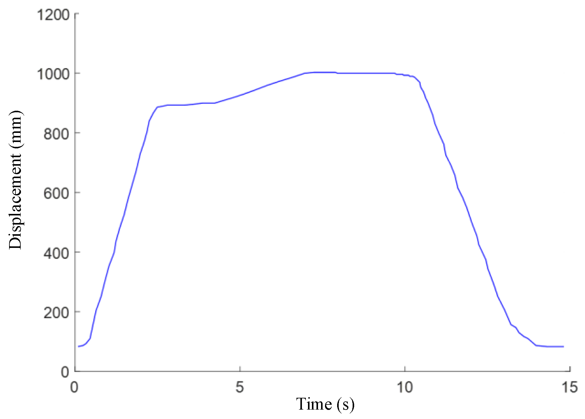
Under eccentric load conditions, when the length of the guide is too short the pressure in the clearances will be too large and the slide may become jammed due to friction. In this case, the wear between the guide rail and guide plate will be intensified. As shown in Figure 5, under the action of the force F1x, the stresses σ1 and σ2 are generated due to the elastic deformation of the rail. The length of each adjustable guide plate is L = L1 + L2. Due to the stress triangle similarity, the relation is given by Equation (24) [23].
{ L 1 2 L 2 2 = N 1 N 2 ( N 2 N 1 ) × ( S + L 2 3 ) = 2 L 3 N 1
Solving these equations results in:
L 1 = L 2 + 3 S L 3 L + 6 S L 2 = 2 L 2 + 3 S L 3 L + 6 S
The friction forces F1′ and F2′, associated with the lateral forces N1 and N2 between the guide plate and the sliding rail, are:
F 1 = N 1 f , F 2 = N 2 f
Based on these expressions, the mechanical equilibrium equations are given by Equation (27):
{ F 1 x h + N 1 ( S + L L 1 3 ) + M e = M a + N 2 ( S + L 2 3 ) F 0 = F 1 + F 2 F 1 x + N 1 = N 2 M a = Y ( 2 Y ) 8 ( Z + Y ) F e ,   M e = Y 2 8 ( Z + Y ) F e
Solving Equation (27), we obtain:
N 1 = 3 ( Y h + S + L 2 3 h ) 8 ( Z + Y ) h L F e ,   N 2 = 2 L + 3 ( Y h + S + L 2 3 h ) 8 ( Z + Y ) h L F e
The equivalent forces N1 and N2 approximately act along the flat surface of the sliding rails. The following constraints should be satisfied in order to avoid failure of the sliding pair:
max ( N 1 b L 1 , N 2 b L 2 ) [ P ]
The wear and associated pressure may be calculated using the work of Archard [24,25], and are given by Equation (30):
h = K c P v t H [ P ] = h H K c v t
If the pressure calculated in the guide clearances does not satisfy the requirement according to Equation (28), the critical pressure [P] may be used to calculate the side force N1 and N2 according to Equation (27), and the slide guide length L is then calculated based on the wear check method. The corresponding optimum clearances δ of the guides can then be calculated based on Equation (6).

4. Case Study

A hydraulic press (RZU2000HM) (Hefei Metrlforming Intelligent Maunfacturing Co., Ltd.: Hefei, China) was investigated as a case study. This press is a sheet metal drawing machine for the front door panel of an automobile. Based on the actual processing parameters, the models and calculation method presented above were used to optimize its slide guide system.

4.1. The Clearances Optimization Based on Energy Loss

The processing parameters for the case study are given in Table 1. ISO 46 hydraulic oil was used in the hydraulic press. The variation of displacement of the slide in a work cycle, T, is shown in Figure 6. At 20 °C, the kinematic viscosity of the hydraulic oil, υ, is 128 mm2/s, and for the an oil proportion S′ of 0.8741, the dynamic viscosity is: μ = Sv × 10−9 = 1.119 × 10⁻⁷ MPa·s. The clearance δ was calculated using Equation (6) as δ = 0.4338 mm.
The energy loss, E, in the cycle T may be found using Equation (7):
E = 2 3 b Δ p 2 δ 3 T μ L + 8 b μ L δ 0 T v ( t ) 2 d t = 5.243 × 10 3 δ 3 + 91.40 δ
The relation between δ and E is shown in Figure 7. It is a nonlinear relationship between the energy loss E and clearances δ. There is an optimum δ corresponding to the minimum E. For the variable velocity in a forming work cycle, the optimal clearances altered. The clearances were optimized based on the designed maximum velocity of the slide, and smaller clearance means heavy assemble and debugging tasks. According to Equation (7), the minimum energy loss is about 6.39 × 10² J when δ is about 0.4 mm.
Under the eccentric load condition, the energy loss in a cycle due to leakage and friction, based on Equations (8)–(12), is about E′ = 1.17 × 10³ J. For the reason that leakage and friction were increased in the clearance with the eccentric load according to the established model. The energy loss under this eccentric load condition increases by approximately 83% when compared to the non-eccentric load condition.

4.2. The Pillars Optimization in Slide Guide System

In order to ensure that the surfaces of the guide rails and adjustable guide plates in the slide guide system will not be badly worn by eccentric loading, the minimum thickness of the oil film must be guaranteed. For δ2 = 0.03 mm [18], the tile angle of the slide is α ≈ (δδ2)/(l/2) = 4.038 × 10⁻⁴ rad. According to Equation (16), the maximum allowable lateral force acting on the guide rails was calculated, and [Fp] is 1.94 × 10⁵ N. Then, the maximum eccentricity, e, in the X direction is 100 mm. According to Equation (13), the eccentric force on the pillar is F1x = 1.83 × 10⁵ N < [Fp]. Thus, the designed clearances meet the requirements under eccentric loading conditions.

4.2.1. Optimization Based on Stiffness Check

The pillars are made of S45C, and the material constants and key pillar variables are provided in Table 2 and Table 3. Under the maximum eccentric load condition in the X direction, according to Equations (13) and (17), the lateral force acting on the pillar F1xmax is 4.2125 × 10⁶ N, axial forces acting on the pillars F0 is 9.0846 × 10⁶ N, and the inertia moment Ix = BH3/12 = 3.0785 × 1010 mm4. Parameter k may be calculated using: k = [F0/(EI)]½ = 3.8412 × 105 mm−1. According to Equations (21)–(23), we obtain:
| δ max | = | F 1 x 2 F 0 k tan k h 4 + F 1 x h 8 F 0 | 0.2903   mm | δ 1 δ 2 | = 0.4038   mm
σ max = 54.8607   MPa [ σ ]
Under the ultimate eccentric load condition in the Y direction, we obtain:
| δ max | = 0.2365   mm | δ 1 δ 2 | ,   σ max = 41.3564   MPa [ σ ]
Therefore, the stiffness and strength of the pillars used in this hydraulic press meet the operational requirements and avoid excessive stiffness. Assuming that the deformation of pillar reached the allowable amount of deformation, which is |δ1δ2| = 0.4038 mm, then, according to Equations (20) and (21), the minimum inertia moments are Ix = 2.2149 × 1010 mm4 and Iy = 1.2048 × 1010 mm4, and the variation of sectional parameters B and H of the pillars, with respect to each other at the given minimum Ix and Iy, is shown in Figure 8. In order to meet the minimum stiffness requirement in both the X and Y directions, the optimal section may be calculated, which is a rectangle with B of 572 mm and H of 775 mm. For these dimensions, the stress intensities in the two directions are:
σ max = 67.1512   MPa [ σ ] ,   σ max * = 56.7040   MPa [ σ ]
As is evident, the strength of the pillars meet the working requirement, and the mass of each pillar is approximately 80.69% of the original mass; this saves about 5540.6 kg of steel for the four pillars.

4.2.2. Optimization Based on Wear Check

According to Equations (24)–(28), for the lengths: L1 = 270.4274 mm and L2 = 289.5726 mm, the following forces are obtained: N1 = 8.2309 × 10⁶ N, N2 = 4.0185 × 10⁶ N. During the forming process of the inner panel of a car front door, the velocity is v ¯ 121.62 mm/s based on Figure 6. The wear coefficient Kc of the bronze guides is 2 × 10⁻¹⁰ under the condition of poor lubrication, and the surface hardness of guide plates on the pillar is H = 590 N/mm2 (HB). For this extreme working condition, the life (work time) of the hydraulic press will be less than 30 days and produce an average wear depth of h′ = 0.03 mm. The contact pressure [P] for these conditions is about 280.74 MPa. Based on Equation (29), the contact pressure calculated in the clearances is within the allowable [P]. Therefore, the length of the siding pair between the pillar and slide satisfies the operational requirement with the clearances satisfying the objective of minimum total power loss.
The length of the guide plane on a slide is another important factor influencing the guide accuracy, and the contact stresses on the guide surface affects the life of the hydraulic machine under eccentric loading. According to the Xinlu [21], the guide length L should be about 0.3 to 0.6 times of the slide height, l. Giving different guide lengths L: 420 < L ≤ 600, N1 and N2 were calculated, and are shown as in Figure 9. Given a minimum length of the guide plane of L = 420 mm, the calculated L1 = 204.63 mm, and L2 = 215.38 mm, so:
max ( N 1 b L 1 , N 2 b L 2 ) = 1.0294 × 10 7 185 × 204.6154 = 271.9277   MPa [ P ]
Therefore, the length L of the adjustable guide plates on the slide lies on the interval (420,600); thus, the wear constraints are met for the sliding pair in the slide guide system. The relations between max (N1,N2) and L and between clearances δ and L are shown in Figure 9. It shows the lateral forces N1 and N2 are reduced with an increase in the guide length. This means the abrasion of the guide rails are decreased with an increase in the guide length L. Additionally, the guide length L is linear as a function of δ, and δ increases with an increase in L. As is evident, for a given guide length, the optimum clearances may be calculated based on the principle of minimum overall energy loss.

5. Summary and Conclusions

A mathematical model of total energy loss in a hydraulic press has been developed that considers the leakage and friction in a slide guide system. Based on the principle of minimum overall energy loss, a method for calculation of optimum clearances was proposed, for which the maximum allowable lateral load may be calculated, which determines the maximum allowable side force that a hydraulic press may undergo.
A stiffness and wear check method for the system under eccentric loading was presented. This method allows for the redesign of the press pillars. Based on an allowable wear constraint associated with the movable crossbeam and pillars, a procedure for calculating of the minimum guide length was proposed.
A case study was considered for a hydraulic press (RZU2000HM). The methods proposed in this paper were used to determine optimum clearances of approximately 0.4 mm. The energy loss was estimated to increase by approximately 83% when subjected to an eccentric loading condition. Using the relations developed herein, the press’ four pillars were redesigned and their weight was reduced by nearly 20% to 80.69%. The length of the guide plates was shown to be reasonable through a wear check. It is believed that the methods developed in this paper may serve as an excellent reference for the optimization of the slide guide system for a hydraulic press.

Acknowledgments

This work is financially supported by the National Natural Science Foundation of China (51135004), Funds for International Cooperation and Exchange of the National Natural Science Foundation of China (51561125002) and Program for New Century Excellent Talents in University of Ministry of Education of China (NCET-12-0837).

Author Contributions

For this article Mengdi Gao developed the models, data measurement for the case study and wrote the paper; Haihong Huang and Zhifeng Liu conceived and designed the verification method; Xinyu Li analyzed the data; John W. Sutherland contributed overall evaluation and revised the paper.

Conflicts of Interest

The authors declare no conflict of interest.

Abbreviations

The following abbreviations are used in this manuscript:
δclearances in slide guide system between slide and pillars
Δpdifferential pressure between the two ends of clearances
Llength of adjustable guide plate on slide
bwidth of adjustable guide plate on slide
μdynamic viscosity of hydraulic oil
V,v(t)velocity of slide
qleakage through the parallel clearances
τliquid shear stress
Fffriction force caused by shearing oil in parallel clearances
PTtotal power loss in parallel clearances
Pqpower loss caused by leakage in parallel clearances
Pfpower loss caused by friction force in parallel clearances
Tworking cycle
Eenergy loss in a working cycle T in parallel clearances
δ1,δ′1sizes of the upper end of the wedge clearances
p1,p′1pressure of inlet in wedge clearances
δ2,δ′2sizes of the lower end of the wedge clearances
aintermediate parameter according to the coordinate system in Figure 2
lheight of slide
ppressure distribution in wedge clearances
αtilt angle of slide
q′leaking caused by the up and down wedge clearances
F′ffriction force caused by shearing oil in wedge clearances
E′unit energy loss in a working cycle T in wedge clearances
[Fp]maximum allowable lateral force under the condition of minimum thickness of oil-film δ1
Fworkingoperational load
Feeccentric moment
F1side thrust
F1xmaximum eccentric load in the X direction
hdistance from lower surface of upper crossbeam to top surface of bottom crossbeam
Zhdistance from force bearing point on guide bush out of plunger in cylinder to the lower surface of upper crossbeam (Z < 1)
Yhdistance from bearing reaction force point on adjustable guide plates of slide to the bottom surface of top crossbeam (Y < 1)
F0total axial force
σ1,σ2distribution stress
L1,L2length of the distribution stress
N1,N2resultant force of the distribution stress
ffriction coefficient
[P]allowable pressure
Kccoefficient of wear
Pcontact pressure
twear time
Hcontact surface hardness
h′average wear depth
ddistance between two pillars
B, Hparameters of the section of pillar

References

  1. Energy Statistics of National Bureau of Statistics of China. China Enrgy Statistical Yearbook 2010; China Statistics Press: Beijing, China, 2010. [Google Scholar]
  2. Wagener, H.-W. New developments in sheet metal forming: Sheet materials, tools and machinery. J. Mater. Process. Technol. 1997, 72, 342–357. [Google Scholar] [CrossRef]
  3. Lee, M.; Kim, C.; Pavlina, E.; Barlat, F. Advances in sheet forming—Materials modeling, numerical simulation, and press technologies. J. Manuf. Sci. Eng. 2011, 133. [Google Scholar] [CrossRef]
  4. Statistical Review of World Energy. Available online: http://www.bp.com/en/global/corporate/about-bp/energy-economics/statistical-review-of-world-energy.html (accessed on 2 June 2015).
  5. Duflou, J.R.; Sutherland, J.W.; Dornfeld, D.; Herrmann, C.; Jeswiet, J.; Kara, S.; Hauschild, M.; Kellens, K. Towards energy and resource efficient manufacturing: A processes and systems approach. CIRP Ann. - Manuf. Technol. 2012, 61, 587–609. [Google Scholar] [CrossRef]
  6. Zhao, K.; Liu, Z.; Yu, S.; Li, X.; Huang, H.; Li, B. Analytical energy dissipation in large and medium-sized hydraulic press. J. Clean. Prod. 2015, 103, 908–915. [Google Scholar] [CrossRef]
  7. Hu, Z.; Dean, T. A study of surface topography, friction and lubricants in metalforming. Int. J. Mach. Tools Manuf. 2000, 40, 1637–1649. [Google Scholar] [CrossRef]
  8. Hasegawa, K.; Inada, A.; Kawachi, N.; Endou, J.-I. Effect of parallel control of press with eccentric load. Steel Res. Int. 2010, 81, 690–693. [Google Scholar]
  9. Osakada, K.; Mori, K.; Altan, T.; Groche, P. Mechanical servo press technology for metal forming. CIRP Ann. - Manuf. Technol. 2011, 60, 651–672. [Google Scholar] [CrossRef]
  10. Wagener, H.; Schlott, C. Influence of die guidance systems on the angular deflection of press slide and die under eccentric loading. J. Mech. Work. Technol. 1989, 20, 463–475. [Google Scholar] [CrossRef]
  11. Zhao, C.C.; Yang, S.F.; Liu, P.P.; Haibin, D. Principle and theoretical analysis of the balancing system for large die forging hydraulic press. J. Mech. Eng. 2012, 10. [Google Scholar] [CrossRef]
  12. Jimma, T.; Sekine, F.; Tozawa, Y. Effect of rigidity of die and press on blanking accuracy of electronic machine parts. CIRP Ann. - Manuf. Technol. 1992, 41, 319–322. [Google Scholar] [CrossRef]
  13. Chval, Z.; Cechura, M. Optimization of power transmission on mechanical forging presses. Proced. Eng. 2014, 69, 890–896. [Google Scholar] [CrossRef]
  14. Socrate, S.; Boyce, M.C. A finite element based die design algorithm for sheet-metal forming on reconfigurable tools. J. Eng. Mater. Technol. 2001, 123, 489–495. [Google Scholar] [CrossRef]
  15. Zhao, H.; Chen, X.-Y.; Dong, Y.-D.; Zhang, J.; Yu, L.-H. Research on lightweight design of press frame structure based on parametric fea. J. Eng. Graph. 2010, 31, 20–25. [Google Scholar]
  16. Arentoft, M.; Wanheim, T. A new approach to determine press stiffness. CIRP Ann. - Manuf. Technol. 2005, 54, 265–268. [Google Scholar] [CrossRef]
  17. Wang, D. The study of hydrostatic slide and its use in the design of machine tool. J. Hydraul. Pneum. Seals 2003, 5, 26–28. [Google Scholar]
  18. Yang, J.; Meng, X. Analysis and application on the optimum restrictive parameters of open hydrostatic sliding way. Lubr. Eng. 2004, 4, 85–86. [Google Scholar]
  19. Erhuang, S. Hydraulic Liquid Fluid Mechanics; National Defence Industry Press: Beijing, China, 1979. [Google Scholar]
  20. Massey, A.W.B. Mechanics of Fluids; Springer: New York, NY, USA, 1989. [Google Scholar]
  21. Xinlu, Y. Hydraulic Press Design and Application; Mechanical Industry Press: Beijing, China, 2006. [Google Scholar]
  22. Gere, J.M.; Timoshenko, S.P. Mechanics of Materials, 2nd ed.; Van Nostrand Reinhold: New York, NY, USA, 1984. [Google Scholar]
  23. Cheng, H.; Liu, Z.; Xie, P.; Zhan, Y.; Yuan, H. Calculation method of minimum length retained in cylinder for swash-plate plunger pump based on energy loss. Trans. Chin. Soc. Agric. Mach. 2014, 45, 333–339. [Google Scholar]
  24. Archard, J. Elastohydrodynamic lubrication of real surfaces. Tribology 1973, 6, 8–14. [Google Scholar] [CrossRef]
  25. Archard, J. Friction between metal surfaces. Wear 1986, 113, 3–16. [Google Scholar] [CrossRef]
Figure 1. A hydraulic press. The inset shows the clearance between the slide and one of the pillars.
Energies 09 00434 g001
Figure 2. The wedge oil-film clearances in hydraulic press between slide and pillars under eccentric loads.
Energies 09 00434 g002
Figure 3. Optimization flow of guidance for slide and pillar of hydraulic press.
Energies 09 00434 g003
Figure 4. Lateral force analysis: (a) eccentric moment acting on the slide, and (b) eccentric loads force acting on hydraulic press.
Energies 09 00434 g004
Figure 5. Force analysis of the pillar.
Energies 09 00434 g005
Figure 6. The displacement of the slide in the forming process of the automobile front door panel.
Energies 09 00434 g006
Figure 7. The energy loss changing with the fit clearances in a work cycle.
Energies 09 00434 g007
Figure 8. The sectional parameters B and H changing with each other for the minimum inertia moment Ix and Iy.
Energies 09 00434 g008
Figure 9. Max (N1, N2) and the fit clearances δ calculated according to different L in the range of (420,600).
Energies 09 00434 g009
Table 1. The data used in the case.
ParametersValueUnit
b185mm
L560mm
v450mm
Δp0.3MPa
l2000mm
p10.3MPa
F20,000kN
h5460mm
d5460mm
H820mm
B670mm
Table 2. The pillar material constants.
ParametersRangesValuesUnit
Elasticity Modulus E200~210200GPa
Poisson Ratio μ0.23~0.330.27
Yield Strength σs≥355MPa
The Allowable Stress [σs]150MPa
Table 3. The parameters of movable crossbeam of the hydraulic press.
ParametersValueUnit
Nominal Press20,000kN
The Size of Workbench and SlideWidth in Left-Right Direction4600mm
Width in Anterior-Posterior Direction2500mm
Height of Slide2000mm
The Working Velocity of SlideQuickly Falls≥450mm/s
Slow Press25–50mm/s
Quickly Returns≥400mm/s

