
Modeling and Experimental Validation of a Volumetric Expander Suitable for Waste Heat Recovery from an Automotive Internal Combustion Engine Using an Organic Rankine Cycle with Ethanol †


Abstract
:
1. Introduction
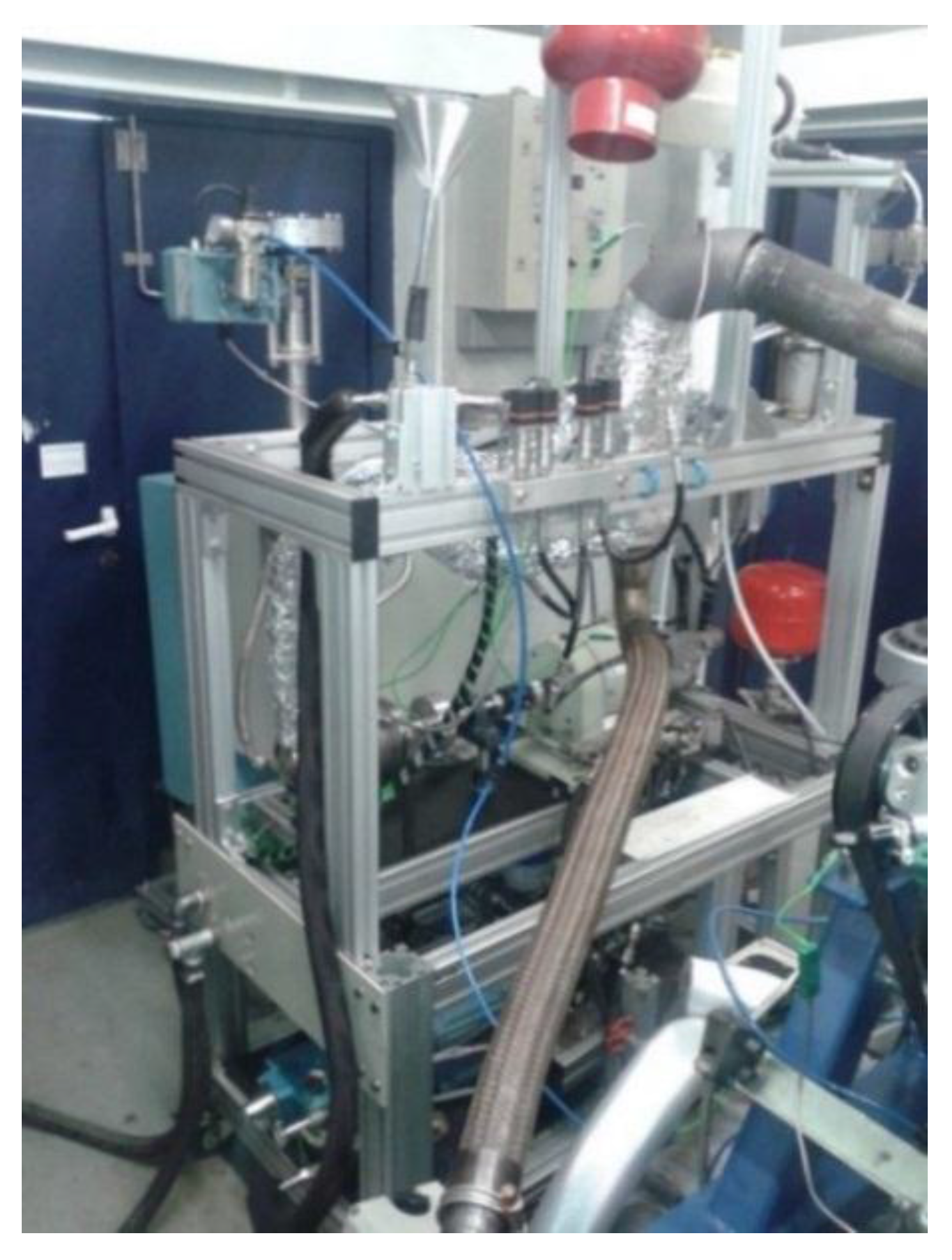
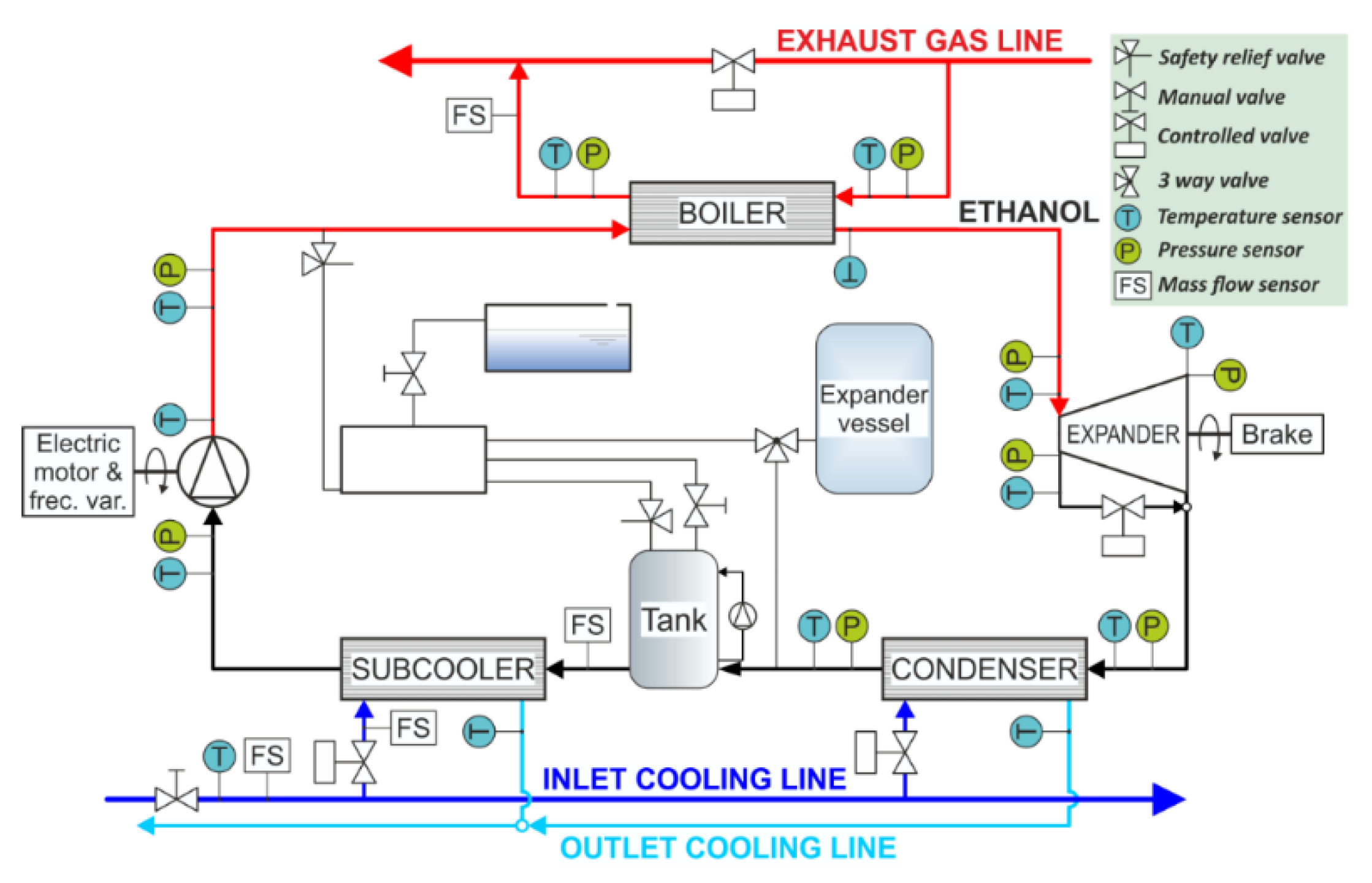
2. System Layout
2.1. Organic Rankine Cycle Layout
2.2. Swash-Plate Expander Layout
3. Modelling
3.1. Global Organic Rankine Cycle Model
3.1.1. Heat Exchangers
3.1.2. Volumetric Expander
3.1.3. Pump
3.1.4. Pipes and Pressure Drops
3.1.5. Expansion Vessel
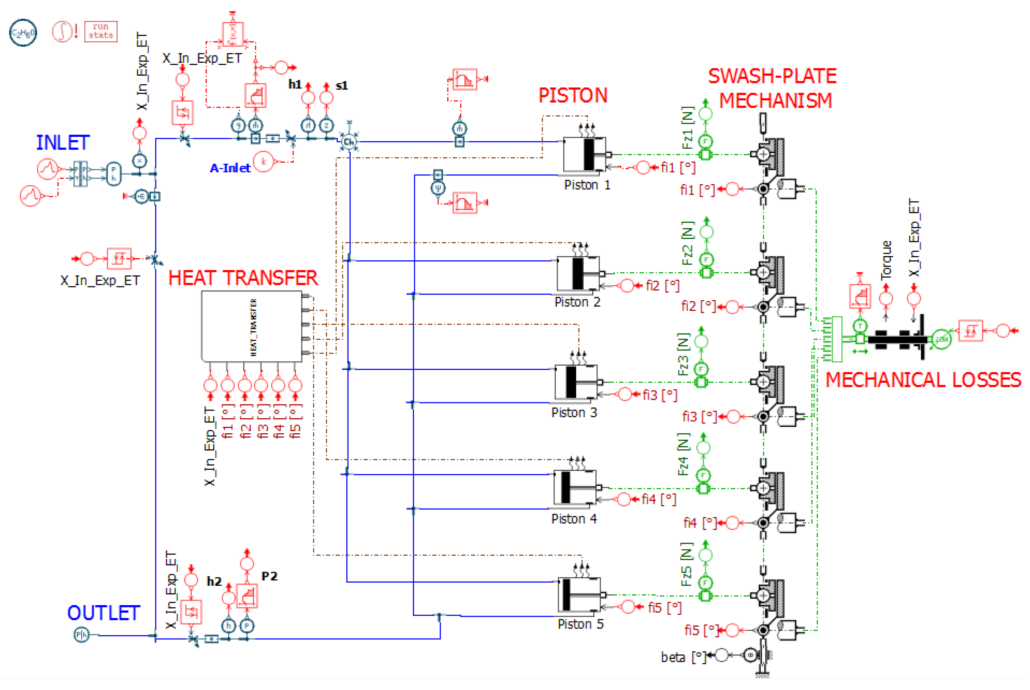
3.2. Swash-Plate Specific Model
- In the heat transfer element: Although the expander was insulated, the expansion and compression do not follow an adiabatic process. The transformation is rather polytropic with a heat exchange between the working fluid and the expander walls due to friction, temperature differences and possible condensation effects in the piston chamber. Therefore, the angle signal was used to consider the angles of compression and expansion and to apply for each process a heat transfer coefficient to model these phenomena.
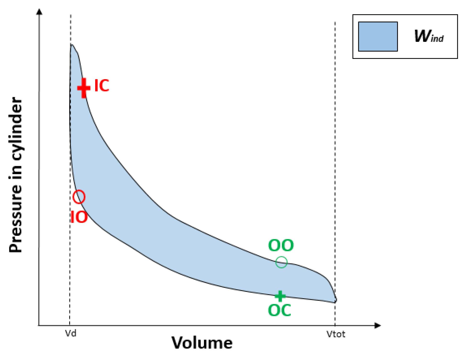
- In the valves: The angle was considered to take into account the discharge coefficient for the intake and the exhaust valve at each particular angle.
- In the rotary-linear transformer: It was considered to calculate the absolute displacement in Equation (7) and therefore the volume variation in Equation (8) of the piston as a function of the swash-plate angle:where Rsw is the radius of the swash-plate (m), αsw is the swash-plate angle (°), is the angle covered by the piston, Vd is the dead volume (m3), B is the bore (m), is the displacement of the piston (m) and is the volume of the piston (m3). No leakages effects have been modelled.
4. Model Validation
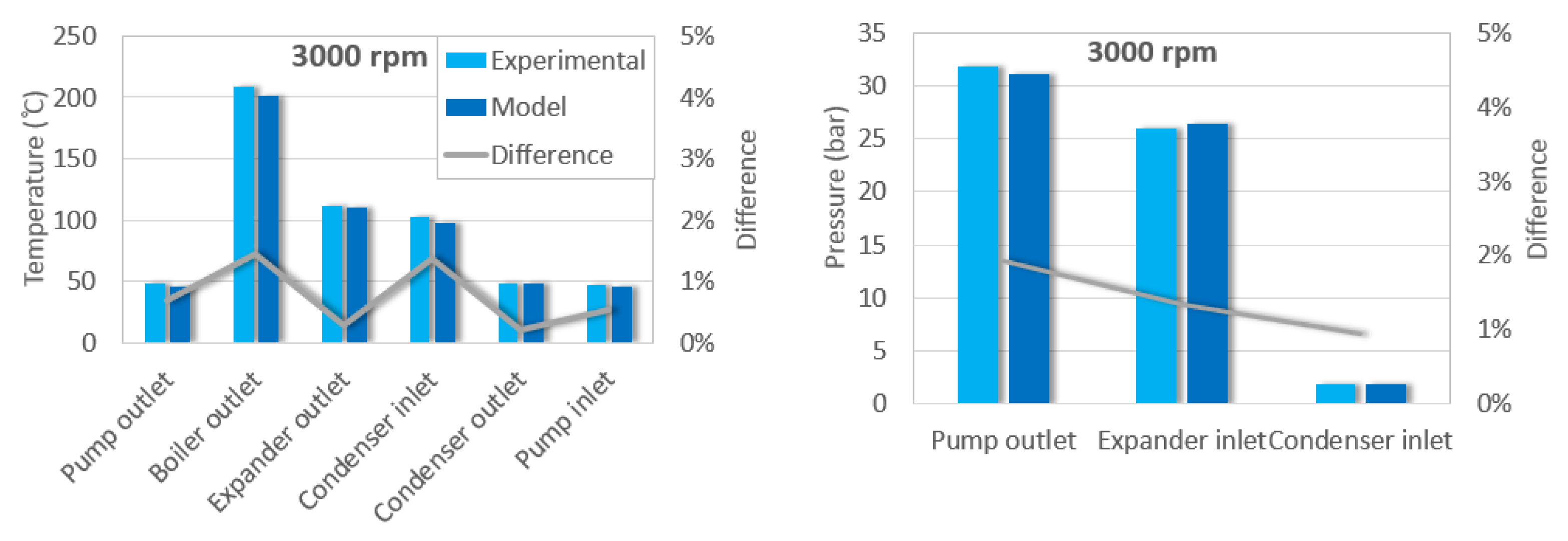
4.1. Global Organic Rankine Cycle Model
4.2. Swash-Plate Specific Model
5. Conclusions
- (1)
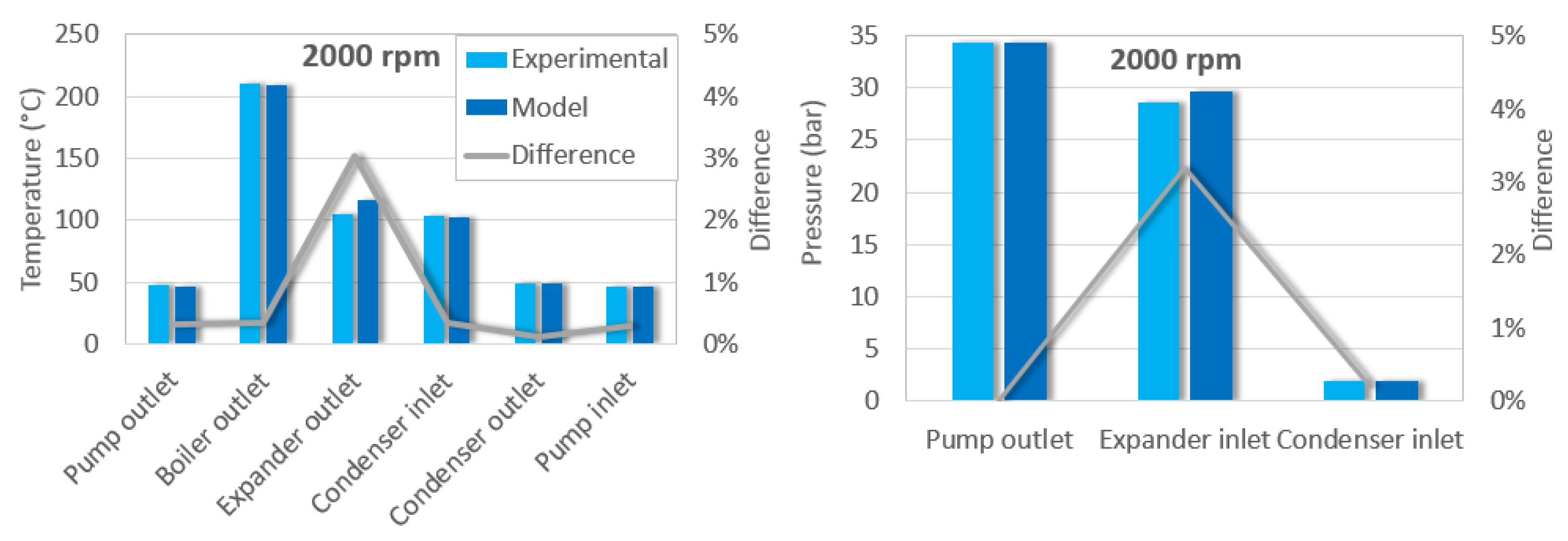
- An ORC model was developed using the software Amesim. This model allows to simulate the main parameters measured in the cycle. Comparing the three steady operating points, a maximum deviation of 4% regarding pressures and temperatures and a value of 5% regarding torque was attained.
- (2)
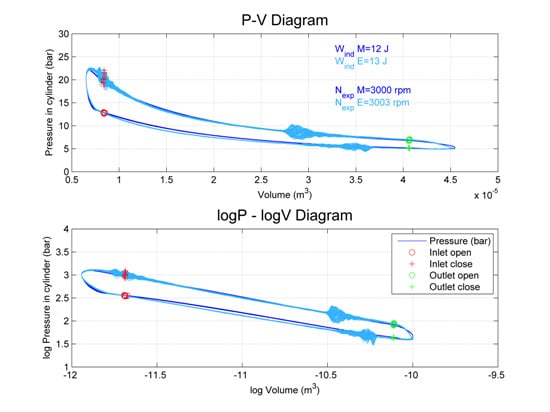
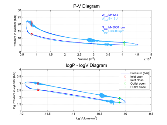
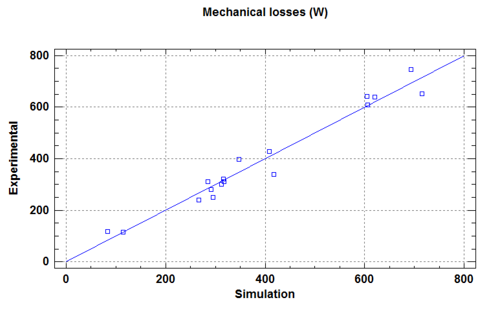
- A swash-plate expander model was presented using the software Amesim. This model represents the fluid dynamic behavior of the swash-plate using discharge coefficients, displacement laws, heat transfer coefficients and mechanical losses. The P-V diagram was measured by a piezoelectric pressure sensor and was compared to the expander model one. Maximum deviation of 10% in indicated power was achieved at point of 3000 rpm.
Acknowledgments
Author Contributions
Conflicts of Interest
Abbreviations
| BDC | Bottom dead center |
| ICE | Internal combustion engine |
| CHP | Combined heat and power |
| WHR | Waste heat recovery |
| NFPA | National fire protection association |
| HD | Heavy duty |
| E | Experimental |
| M | Modelled |
| ORC | Organic Rankine cycle |
| P-V | Pressure volume |
| TDC | Top dead center |
| TPF | Two phase flow |
| ODP | Ozone depletion potential |
| GWP | Global warming potential |
Nomenclature
| η | Efficiency |
| Power (kW) | |
| Work (J) | |
| N | Expander speed (rpm) |
| Mass flow (kg/h) | |
| P | Pressure (bar) |
| T | Temperature (°C) |
| Density (kg/m3) | |
| n | Number of cylinders |
| Pi | State point i |
| τ | Torque (Nm) |
| Disp | Displacement single cylinder (m3) |
| Vd | Dead volume (m3) |
| B | Cylinder bore (m) |
| Rswash | Radius of the swash-plate (m) |
| X | Displacement covered by the piston (m) |
| V | Volume covered by the piston (m) |
Subscript
| ET | Ethanol |
| W | Water |
| EG | Exhaust gases |
| PP | Pump |
| Exp | Expander |
| C | Condenser |
| B | Boiler |
| In | Inlet |
| Out | Outlet |
| Iso | Isentropic |
| Ind | Indicated |
| S | Shaft |
| Vol | Volumetric |
| Mec | Mechanical |
| cyl | Cylinder |
References
- Saidur, R.; Rezaei, M.; Muzammil, W.K.; Hassan, M.H.; Paria, S.; Hasanuzzaman, M. Technologies to recover exhaust heat from internal combustion engines. Renew. Sustain. Energy Rev. 2012, 16, 5649–5659. [Google Scholar] [CrossRef]
- Yang, J. Potential Applications of Thermoelectric Waste Heat Recovery in the Automotive Industry. In Proceedings of the 24th International Conference on Thermoelectric 2005 ICT, Clemson, SC, USA, 19–23 June 2005; pp. 170–174.
- Apostol, V.; Pop, H.; Dobrovicescu, A.; Prisecaru, T.; Alexandru, A.; Prisecaru, M. Thermodynamic analysis of ORC configurations used for WHR from a turbocharged diesel engine. Procedia Eng. 2015, 100, 549–558. [Google Scholar] [CrossRef]
- Conklin, J.C.; Szybist, J.P. A highly efficient six-stroke internal combustion engine cycle with water injection for in-cylinder exhaust heat recovery. Energy 2010, 35, 1658–1664. [Google Scholar] [CrossRef]
- Dolz, V.; Novella, R.; García, A.; Sánchez, J. HD Diesel engine equipped with a bottoming Rankine cycle as a waste heat recovery system. Part 1: Study and analysis of the waste heat energy. Appl. Therm. Eng. 2012, 36, 269–278. [Google Scholar] [CrossRef]
- Serrano, J.R.; Dolz, V.; Novella, R.; García, A. HD Diesel engine equipped with a bottoming Rankine cycle as a waste heat recovery system. Part 2: Evaluation of alternative solutions. Appl. Therm. Eng. 2012, 36, 279–287. [Google Scholar] [CrossRef]
- Bracco, R.; Clemente, S.; Micheli, D.; Reini, M. Experimental tests and modelization of a domestic-scale ORC (Organic Rankine Cycle). Energy 2013, 58, 107–116. [Google Scholar] [CrossRef]
- Lecompte, S.; Huisseune, H.; Van den Broek, M.; De Schampheleire, S.; De Paepe, M. Part load based thermo-economic optimization of the Organic Rankine Cycle (ORC) applied to a combined heat and power (CHP) system. Appl. Energy 2013, 111, 871–881. [Google Scholar] [CrossRef]
- Manente, G.; Toffolo, A.; Lazzaretto, A.; Paci, M. An organic Rankine cycle off-design model for the search of the optimal control strategy. Energy 2013, 58, 97–106. [Google Scholar] [CrossRef]
- Quoilin, S.; Lemort, V.; Lebrun, J. Experimental study and modeling of an Organic Rankine Cycle using scroll expander. Appl. Energy 2010, 87, 1260–1268. [Google Scholar] [CrossRef]
- Wei, D.; Lu, X.; Lu, Z.; Gu, J. Dynamic modeling and simulation of an Organic Rankine Cycle (ORC) system for waste heat recovery. Appl. Therm. Eng. 2008, 28, 1216–1224. [Google Scholar] [CrossRef]
- Ziviani, D.; Beyene, A.; Venturini, M. Advances and challenges in ORC systems modeling for low grade thermal energy recovery. Appl. Energy 2014, 121, 79–95. [Google Scholar] [CrossRef]
- Mendoza, L.C.; Navarro-Esbrí, J.; Bruno, J.C.; Lemort, V.; Coronas, A. Characterization and modeling of a scroll expander with air and ammonia as working fluid. Appl. Therm. Eng. 2014, 70, 630–640. [Google Scholar] [CrossRef]
- Cipollone, R.; Bianchi, G.; Di Battista, D.; Contaldi, G.; Murgia, S. Mechanical energy recovery from low grade thermal energy sources. Energy Procedia 2014, 45, 121–130. [Google Scholar] [CrossRef]
- Ferrara, G.; Manfrida, G.; Pescioni, A. Model of a small steam engine for renewable domestic CHP (combined heat and power) system. Energy 2013, 58, 78–85. [Google Scholar] [CrossRef]
- Giuffrida, A. Modelling the performance of a scroll expander for small organic Rankine cycles when changing the working fluid. Appl. Therm. Eng. 2014, 70, 1040–1049. [Google Scholar] [CrossRef]
- Lemort, V.; Quoilin, S.; Cuevas, C.; Lebrun, J. Testing and modeling a scroll expander integrated into an Organic Rankine Cycle. Appl. Therm. Eng. 2009, 29, 3094–3102. [Google Scholar] [CrossRef]
- Qiu, G.; Liu, H.; Riffat, S. Expanders for micro-CHP systems with organic Rankine cycle. Appl. Therm. Eng. 2011, 31, 3301–3307. [Google Scholar] [CrossRef]
- Seher, D.; Lengenfelder, T.; Gerhardt, J.; Eisenmenger, N.; Hackner, M.; Krinn, I. Waste Heat Recovery for Commercial Vehicles with a Rankine Process. In Proceedings of the 21st Aachen Colloquium Automobile and Engine Technology, Aachen, Germany, 11 October 2012; pp. 7–9.
- Howell, T.; Gibble, J. Development of an ORC System to Improve HD Truck Fuel Efficiency. In Proceedings of Deer Conference, Deer, MA, USA, 5 October 2011; pp. 1–21.
- Galindo, J.; Ruiz, S.; Dolz, V.; Royo-Pascual, L.; Haller, R.; Nicolas, B.; Glavatskaya, Y. Experimental and thermodynamic analysis of a bottoming Organic Rankine Cycle (ORC) of gasoline engine using swash-plate expander. Energy Convers. Manag. 2015, 103, 519–532. [Google Scholar] [CrossRef]
- Macián, V.; Serrano, J.R.; Dolz, V.; Sánchez, J. Methodology to design a bottoming Rankine cycle, as a waste energy recovering system in vehicles. Study in a HDD engine. Appl. Energy 2013, 104, 758–771. [Google Scholar] [CrossRef]
- Shah, M.M. A general correlation for heat transfer during film condensation inside pipes. Int. J. Heat Mass Transf. 1979, 22, 547–556. [Google Scholar] [CrossRef]
- Steiner, D.; Taborek, J. Flow boiling heat transfer in vertical tubes correlated by an asymptotic model. Heat Transf. Eng. 1992, 13, 43–69. [Google Scholar] [CrossRef]
- Churchill, S.W. Friction-factor equation spans all fluid flow regimes. Chem. Eng. 1977, 84, 91–92. [Google Scholar]
- McAdams, W.H.; Woods, W.K.; Heroman, L.C. Vaporization inside horizontal tubes -II- Benzene-oil mixtures. Trans. ASME 1942, 64, 193–200. [Google Scholar]


| References | Model Features | Software | Max. Power | Working Fluid |
|---|---|---|---|---|
| [7] | ORC with a scroll expander | Amesim | 1.5 kW (mechanical) | R245fa |
| [8] | ORC for CHP with a volumetric expander | Matlab with RefProp | 207 kW (output) | R152a, R1234yf, R245fa |
| [9] | Dynamic ORC model with a turbine | Matlab (Simulink) | 8 MW (net power) | Isobutene and R134a |
| [10] | ORC with a scroll expander | EES | 1.8 kW (mechanical) | HCFC-123 |
| [11] | Dynamic ORC model with a turbine | Modelica and Dymola | 100 kW | R245fa |
| [12] | ORC with a scroll expander | Amesim | 2.16 kW (mechanical) | R245fa |
| [13] | Scroll expander | - | 260 W (mechanical) | Air and ammonia |
| [14] | Sliding vane rotary expander | - | 2 kW (mechanical) | R236fa |
| [15] | Reciprocating expander | WAVE Ricardo Software and EES | 2.26 kW (output) | Water |
| [16] | Scroll expander | Matlab with Refprop | 2 kW (mechanical) | Several fluids |
| [17] | Scroll expander | - | 1.8 kW (mechanical) | HCFC-123 |
| Variable Measured | Type | Range | Accuracy |
|---|---|---|---|
| Exhaust gas pressure | Piezoresistive | 0–2 bar | 0.05% full scale |
| Ethanol high pressure loop | Piezoresistive | 0–50 bar | 0.05% full scale |
| Ethanol low pressure loop | Piezoresistive | 0–5 bar | 0.05% full scale |
| Temperatures | K-type thermocouples (Class 2) | 0–1100 °C | ±2.5 °C |
| Ethanol flow meter | Coriolis flow meter | 0–2720 kg/h | ±0.1% |
| Water flow meter | Electromagnetic flow sensor | 0.3–1 m/s | ±0.5% of rate |
| Expander rotational speed | Optical tachymeter | 0–20,000 rpm | ±1 rpm |
| Expander torque meter | Strain gauges | 0–200 Nm | 0.05% full scale |
| Pistons Number | Bore | Stroke | Maximum Expander Speed |
|---|---|---|---|
| 5 | 40 | 31 | 4500 |
| - | mm | mm | rpm |
| Property | Ethanol | ||
|---|---|---|---|
| Chemical formula | C2H6O | ||
| Critical temperature | Tc | 240.9 | °C |
| Critical pressure | Pc | 61.4 | bar |
| Atmospheric boiling point | Tb | 78.3 | °C |
| Ozone depletion potential | ODP | 0 | - |
| Global warming potential | GWP | n/a | - |
| NFPA health hazard | H | 2 | - |
| NFPA flammability hazard | F | 3 | - |
| Auto ignition temperature | Tign | 363 | °C |
| Variable | P1 | P2 | P3 | Units |
|---|---|---|---|---|
| 73.85 | 75.99 | 74.79 | kg/h | |
| P_in_PP_ET | 1.571 | 1.899 | 1.589 | bar |
| NExp | 2001 | 2502 | 3003 | rpm |
| T_in_B_EG | 749.5 | 740 | 749 | °C |
| P_out_B_EG | 1.018 | 1.024 | 1.018 | bar |
| 154.98 | 159.47 | 155.25 | kg/h | |
| T_in_C_W | 48.5 | 49 | 48 | °C |
| Variable | P1 | P2 | P3 | Units |
|---|---|---|---|---|
| ind | 1739 | 2007 | 1874 | W |
| mec | 1649 | 1543 | 1531 | W |
| iso | 3431 | 3413 | 3338 | W |
| ηvol | 19.37% | 17.21% | 14.54% | - |
| ηiso | 50.68% | 58.81% | 56.14% | - |
| ηmec | 94.81% | 76.90% | 81.72% | - |
| ηglob | 48.05% | 45.22% | 45.88% | - |
| Variable | P1 E | P1 M | Difference | P2 E | P2 M | Dif. | P3 E | P3 M | Dif. | Units |
|---|---|---|---|---|---|---|---|---|---|---|
| T_out_PP_ET | 47.5 | 46.5 | 0.31% | 47 | 46 | 0.25% | 48.5 | 46 | 0.70% | °C |
| T_out_B_ET | 210 | 209 | 0.33% | 215 | 199 | 3.28% | 208 | 201 | 1.44% | °C |
| T_out_Exp_ET | 105 | 116 | 3.04% | 109 | 107 | 0.50% | 111 | 110 | 0.30% | °C |
| T_in_C_ET | 104 | 102.5 | 0.33% | 103 | 99 | 1.16% | 102 | 97 | 1.37% | °C |
| T_out_C_ET | 48 | 48.5 | 0.10% | 48 | 48.5 | 0.17% | 48 | 48.5 | 0.22% | °C |
| T_in_PP_ET | 46.5 | 46 | 0.28% | 46.5 | 46 | 0.23% | 47.5 | 46 | 0.53% | °C |
| T_out_C_W | 74 | 71 | 0.71% | 67 | 69 | 0.52% | 73 | 71.5 | 0.38% | °C |
| P_out_PP_ET | 34.26 | 34.26 | 0.01% | 31.01 | 31.48 | 1.51% | 31.77 | 31.16 | 1.92% | bar |
| P_in_Exp_ET | 28.65 | 29.57 | 3.20% | 27.00 | 26.53 | 1.74% | 26.01 | 26.36 | 1.33% | bar |
| P_in_C_ET | 1.89 | 1.89 | 0.20% | 2.01 | 2.10 | 4.48% | 1.90 | 1.88 | 0.95% | bar |
| τExp | 7.81 | 7.98 | 2.18% | 5.86 | 5.59 | 4.47% | 4.87 | 4.96 | 1.85% | Nm |
| Variable | P1 | P2 | P3 | Units | I/O |
|---|---|---|---|---|---|
| Pin_Exp_ET | 28.65 | 27.00 | 26.01 | bar | Input |
| NExp | 2001 | 2502 | 3003 | rpm | Input |
| ind_E | 18 | 16 | 13 | J | - |
| ind_M | 20 | 15 | 12 | J | Output |
| ind_E | 1739 | 2007 | 1874 | W | - |
| ind_M | 1857 | 1877 | 1678 | W | Output |
| Dif. Power (%) | 6.79% | 6.48% | 10.46% | - | - |
© 2016 by the authors; licensee MDPI, Basel, Switzerland. This article is an open access article distributed under the terms and conditions of the Creative Commons by Attribution (CC-BY) license (http://creativecommons.org/licenses/by/4.0/).
Share and Cite
Galindo, J.; Dolz, V.; Royo-Pascual, L.; Haller, R.; Melis, J. Modeling and Experimental Validation of a Volumetric Expander Suitable for Waste Heat Recovery from an Automotive Internal Combustion Engine Using an Organic Rankine Cycle with Ethanol. Energies 2016, 9, 279. https://doi.org/10.3390/en9040279
Galindo J, Dolz V, Royo-Pascual L, Haller R, Melis J. Modeling and Experimental Validation of a Volumetric Expander Suitable for Waste Heat Recovery from an Automotive Internal Combustion Engine Using an Organic Rankine Cycle with Ethanol. Energies. 2016; 9(4):279. https://doi.org/10.3390/en9040279
Chicago/Turabian StyleGalindo, José, Vicente Dolz, Lucía Royo-Pascual, Regine Haller, and Julien Melis. 2016. "Modeling and Experimental Validation of a Volumetric Expander Suitable for Waste Heat Recovery from an Automotive Internal Combustion Engine Using an Organic Rankine Cycle with Ethanol" Energies 9, no. 4: 279. https://doi.org/10.3390/en9040279