1. Introduction
In recent years, several studies have underlined the potential of low-grade heat recovery to reduce the amount of worldwide industrial energy consumption [
1]. Organic Rankine cycle (ORC) systems are considered a viable and mature technology for waste heat recovery applications in the standard power range (from hundreds of
to a few
) [
2,
3]. On the other hand, for micro-WHR applications, the highly fluctuating nature of the heat source makes the development of a reliable ORC unit a challenging task [
4,
5]. The objectives to optimally operate an ORC power unit for WHR applications can be synthesized in the two following points: (1) keep the cycle in safe working conditions, to preserve the components’ life expectancy; (2) maximize the ORC unit net output power, to boost energy production and decrease the payback-time of the installation [
6]. In order to achieve these goals, the development of a reliable and effective control strategy able to meet the industrial requirements of simplicity is deemed necessary.
As far as safe working conditions are concerned, a minimum level of superheating must be ensured at the inlet of the expander in order to avoid the formation of liquid droplets that could damage the expansion machine [
7,
8]. Several contributions focusing on the development of control strategies to ensure safe working conditions are available in the literature. Traditional control strategies could not offer satisfactory results, as illustrated in [
9], where a supervisory predictive control scheme is necessary to achieve the desired performance. Similarly, in [
10], the authors implement a predictive functional control and compare its performance to PI controllers, showing that the main challenge for the controller is superheating regulation. Further efforts on better tuning PI-like strategies are reported in [
11], where gain-scheduling and feed-forward are implemented to improve PI performance. In [
12], an explicit multi-model predictive controller is used to regulate the superheating of an ORC mounted on a heavy duty truck. Multivariable predictive control strategies are also studied as reported in [
13,
14].
Most of these studies are restricted to guaranteeing safety conditions by regulating the superheating, but little attention has been paid to the performance of the power unit in terms of energy production. In order to maximize the output power, the evaporating temperature is usually considered as the most relevant controlled variable [
15,
16]. In [
17], the modeling and control of a waste heat recovery system for a Euro-VI heavy-duty truck engine was achieved through the use of a switching model predictive control strategy to guarantee the safe operation of the WHR system and to maximize output power. Furthermore, in the automotive field, the problem of maximizing the power produced by an ORC waste heat recovery system on board a diesel-electric rail car is tackled using dynamic real-time optimization [
18]. In [
16], an experimental study is conducted using an
pilot plant, showing that the constrained model predictive control (MPC) outperforms PID-based strategies, as it allows one to accurately regulate the evaporating temperature with a lower control effort while keeping the superheating in a safer operating range.
The latest contributions available in the literature indicate a clear trend towards the preferential use of advanced model-based controllers, especially predictive controllers, over the more traditional PID-based strategy. This is due to their ability to ensure safe and optimal working conditions, especially for WHR applications characterized by highly transient heat source profiles.
In this contribution, we propose a two-layer control structure consisting of a perturbation-based extremum seeking (ES) algorithm coupled to a constrained MPC to guarantee safe and optimal working operation for a stationary sub-critical ORC unit for a WHR application.
Extremum seeking is a well-developed research area that addresses the problem of objective value optimization when the objective function, its gradient and optimum value are unknown [
19]. To the best of our knowledge, work has been proposed to optimize vapor compression cycles [
20,
21,
22] using ES schemes, but this has never been applied to ORC systems. A possible drawback for ES algorithms appears when the extremum causes other variables to violate safety limits. One option to tackle this situation is to design a complex ES algorithm that accounts for constraints, as proposed in [
23]. In the present work, we propose to use a simple ES algorithm and let a lower level controller deal with the constraints, e.g., taking actions where the superheating is below a threshold value.
The extended prediction self-adaptive control (EPSAC) approach to constrained model predictive control is proposed as the lower level control strategy. Since it uses input/output models for prediction and not state-space models, as in other MPC algorithms [
24], it avoids the need for state estimators, making it a suitable tool for industrial applications. More traditional PI-like strategies are developed for the sake of comparison with the proposed EPSAC-MPC strategy, including a PI controller to regulate superheating at a constant operating point, as is very often done in industrial practice. The control strategies are implemented in MATLAB and tested at the simulation level on a validated nonlinear dynamic model developed in the Modelica language [
25]. The coupling between the two software is achieved through the Functional Mockup Interface (FMI) standard. Furthermore, in order to assess the capabilities of the ES algorithm to identify the optimal evaporating condition, the ES algorithm results are compared to the optimal evaporating temperature profile obtained off-line through the nonlinear dynamic model of the ORC unit.
The paper is structured as follows: a description of the
sub-critical ORC power system and of the unit Modelica model is presented in
Section 2, followed by a description of the adaptive extremum seeking algorithm in
Section 3. In
Section 4, the EPSAC-MPC algorithm is formulated.
Section 5 is dedicated to the main simulation results and
Section 6 to providing some guidelines to tune the extremum seeking algorithm. Finally, a conclusion section summaries the main outcome of this contribution.
2. Process Description
This section describes the architecture and main characteristics of the ORC system used for evaluating the performance of the developed control strategies.
2.1. The Organic Rankine Cycle System
The ORC power unit investigated in this work is a sub-critical experimental unit for stationary low temperature waste heat recovery. The rig is installed at Ghent University campus Kortrijk. The system is based on a regenerative cycle and employs Solkatherm (SES36) as the working fluid. The expander is originally a single-screw compressor adapted to run in expander mode. It drives an asynchronous generator connected to the electric grid through a four-quadrant inverter, which allows varying the generator rotational speed (). The circulating pump is a vertical variable-speed 14-stage centrifugal pump with a maximum pressure of 14 bar and nominal power.
Three identical brazed plate heat exchangers are used for the evaporator, internal heat exchanger and condenser. The evaporator is insulated with a glass wool layer of a 180-mm thickness. The Coriolis flow meter enables a direct measurement of the working fluid mass flow rate. Absolute pressure sensors with a range of 0–16 bar are used in conjunction with built-in 4–20-mA transmitters to measure the pressures.
The low-capacity waste heat thermal energy source is ensured by means of an electrical boiler where thermal oil, Therminol66, is pumped through to temperatures of up to C. The boiler has a maximum power of . A PI (proportional integral) controller is implemented to maintain a constant oil temperature at the inlet of the evaporator during transients (e.g., change of ORC pump rotational speed).
A variable flow rate of glycol water ( ethylene glycol of total volume ) is used to cool down the working fluid in the condenser. The thermal energy is rejected by the cooling fluid to the ambient environment by means of an air cooler. A by-pass of the air cooler allows controlling the condenser cooling fluid inlet temperature by means of an adjustable solenoid valve.
Starting from the bottom of the scheme (
Figure 1), it is possible to recognize the liquid receiver (b) installed at the outlet of the condenser (a) where the fluid is collected in saturated liquid condition. From the receiver outlet, the fluid is pumped (c) through the re-generator (d) cold side and the evaporator (e), where it is heated up to superheated vapor, reaching its maximum temperature at the evaporator outlet. The fluid, after being expanded in the volumetric machine (f), enters the re-generator hot side, and then, it flows into the condenser (a) to close the cycle. The interested reader can refer to [
26] for a more detailed description of the ORC test-rig.
2.2. The ORC Unit Modelica Model
In order to assess the performance of the different developed control strategies, a dynamic model of the ORC system presented in
Figure 1 has been developed in the Modelica language using existent components from the ThermoCycle library [
27]. Dymola is selected as the simulation environment software. The finite volume (FV) modeling approach is used to simulate the three heat exchanger components of the unit. The FV method consists of discretizing the heat exchanger (HE) volume in a number of equal and constant control volumes. It is considered a reliable and robust approach for the modeling of HE involving two-phase fluid flows [
25,
28].
As the time constants characterizing the compression and expansion processes are negligible compared to the ones characterizing the mass and heat transfer phenomena in the heat exchangers, the pump and the expander are described with semi-empirical quasi-steady-state models. A description of these models is reported in [
29]. The liquid receiver at the condenser outlet is modeled assuming thermodynamic equilibrium at all times. Pressure drops in the heat exchangers are lumped at the lowest vapor density section of the ORC system and are modeled according to a quadratic law accounting for linear and turbulent effects [
15].
The thermo-physical properties of the working fluid (SES36), the cooling fluid (glycol-water) and the thermal oil (therminol66) are computed coupling Modelica with the open-source fluid properties’ library CoolProp [
30] through the use of the ExternalMedia package [
27]. For a more detailed description of the modeling approach, the interested reader can refer to [
25].
The developed Modelica model is then exported into the Simulink/MATLAB environment by means of the Functional Mockup Interface (FMI) open standard, using a model exchange format. This simulation approach takes advantage of the strengths of each platform: Modelica for modeling and Simulink/MATLAB for control design. The presented simulation results are performed with an expander rotational speed set constant at , so as to emulate an installation directly connected to the grid.
2.3. ORC Unit Optimal Working Conditions
In order to optimally operate a sub-critical ORC unit for waste heat recovery applications, two main conditions need to be satisfied: (1) ensure safe working operation; and (2) maximize the net output power.
As far as safety operations are concerned, a super-heated vapor state must be ensured at the expander inlet. In applied thermodynamic terms, an accurate regulation of the superheating () is deemed fundamental to avoid a wet expansion: the formation of liquid droplets during the expansion process that could damage the machine.
The superheating is defined as:
where
is the temperature measured at the inlet of the expander and
the evaporating temperature at the evaporating pressure
.
For waste heat recovery applications in order to optimize the ORC unit performance, the net output power needs to be maximized during operation. In this regard, the evaporating temperature is considered the most relevant control variable [
16]. The net output power is selected as the most relevant performance index and is defined by:
The cycle first law efficiency is also provided for indicative purposes and is defined by:
where
is the expander electrical power,
is the pump electrical power and
is the thermal power supplied to the ORC working fluid in the evaporator.
2.4. ORC Unit Model-Based Investigation
The developed Modelica dynamic model is used to gain insight into the system’s dynamics, in particular the relationship between superheating (), evaporating temperature (), pump speed () and expander electrical power ().
The system is perturbed by applying
step changes on the pump rotational speed in the range between 1300 and 2100
for different heat source conditions. The heat source temperature,
, is varied between 90 and
C while the heat source mass flow,
, is comprised of a range between
and
. The heat sink temperature,
, and heat sink mass flow,
, were kept constant at
C and
, respectively. The steady-state values obtained at each pump speed are depicted in
Figure 2, where the expander electrical power
is represented as a function of
and
.
Figure 2a illustrates that for each heat source condition, there exists an optimal evaporating temperature that maximizes the expander output power: as an example, for a heat source of
and
C, an optimum is reached for
C, corresponding to an output power of
.
As the pump speed is increased, the working fluid mass flow and the superheating decreases, extracting more thermal energy from the heat source and consequently leading to an electrical power increment. In
Figure 2b, the influence of the pump speed and the superheating level on the expander output power is reported. Once the superheating reaches zero (
i.e., the fluid is in the two-phase condition), the expander power drops.
The model-based investigation allows one to conclude that the ORC unit output power is inversely proportional to the degree of superheating in the evaporator, and it exhibits an optimum as a function of the evaporating temperature. For limited values of the superheating (e.g., lower than C), the gain in output power remains limited (about ), which indicates an acceptable target range for the control.
Based on the acquired simulation data, it is possible to derive a correlation describing the optimal evaporating temperature as a function of the heat source conditions:
Equation (4) is valid in the range of
and
C given a constant saturation temperature in the condenser of
. It is computed considering a minimum superheating value of
C, as represented by the black circles in
Figure 2 and provides an accuracy of
.
Based on the obtained simulation results, it is concluded that the design of a control strategy focusing on the regulation of the evaporating temperature while ensuring a minimum amount of superheating is deemed necessary for optimal operation. Controlling the expander speed or turbine guide vanes is not considered in the present work, since it constitutes an additional system complexity and cost and is not implemented in most commercial ORC systems [
4].
3. Adaptive Optimization
The identification of the optimal evaporating temperature is a fundamental step towards the implementation of a control strategy aimed at maximizing the output power of the sub-critical ORC unit. If a dynamic model of the system is available and calibrated for the target system, an optimal correlation can be developed, which further satisfies the system safety constraints (cf. Equation (4)). However, there are two drawbacks in this approach: (1) a validated dynamic model is not always available; (2) model errors can bias the computed optimal operating conditions.
In order to overcome these issues, we propose a different approach based on the implementation of an extremum seeking (ES) algorithm. Such an approach allows identifying the optimal evaporating temperature, without the need for a model of the investigated system. Extremum seeking is a well-developed field that addresses the problem of objective value optimization when the objective function, its gradient and optimum value are unknown [
19]. From the different algorithm variations, the perturbation-based ES framework is the most popular method in the literature [
19], as it has proven to be more robust to noise and dynamic effects in the system, thus producing smoother references, which decrease the risk of instability [
31].
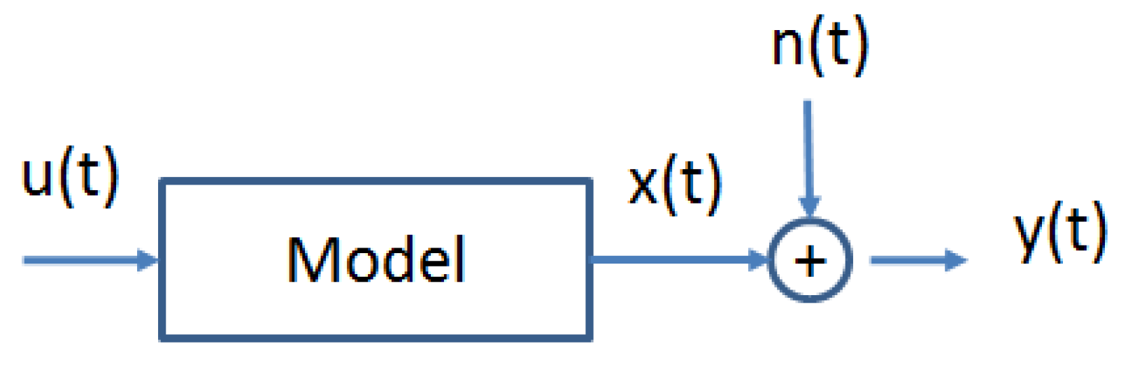
The schematic representation of the proposed control structure is depicted in
Figure 3. The perturbation-based ES algorithmis in charge of finding the extremum
that arises from the reference-to-output nonlinear map (
i.e.,
to
), while a low-level feedback controller keeps the system stable at that equilibrium optimal point.
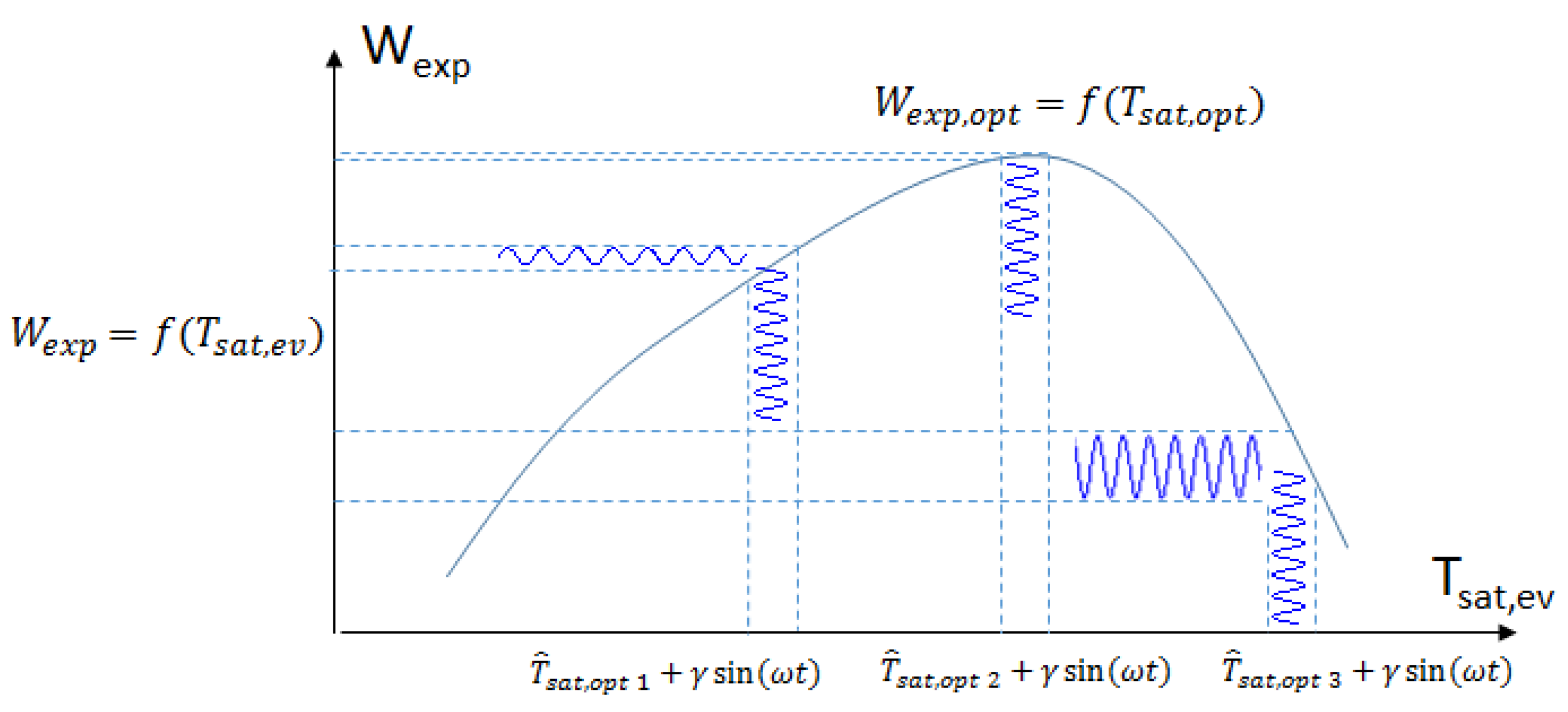
The working principle of the ES algorithm is depicted in
Figure 4. The ES algorithm estimates the gradient of the nonlinear mapping,
f, by perturbing its input with a periodic dither signal with radial frequency
ω and by processing its output
. Although the relationship between
and
is nonlinear and
a priori unknown, it is assumed that an extremum
exists.
In this study, the dither signal is assumed to be a sine wave, although other types of dither can be used, as well [
32].
Figure 4 shows the response of a nonlinear function with a global maximum to such a sinusoidal perturbation signal around three different
. At
,
, resulting in an inversion of the dither signal phase in the output of the nonlinear function. Instead, at
,
, the phase of the dither signal component remains unchanged.
The perturbation around results in a larger amplification of the dither signal, compared to perturbation around . Around , which is close to the extremum , the dither signal is hardly visible in the output, because . Furthermore, in this figure, . Intuitively, the dither signal component in the output can be regarded as an estimate of the local gradient around a certain
The reference to the low-level controller consists of the sine wave dither signal and an adaptation input:
where
γ is the amplitude and
ω is the modulation frequency. The adaptation signal,
, shifts the sine wave towards the gradient direction. The response of the system to this signal is measured in the objective value (
). This output is filtered by a high-pass filter to eliminate the DC component and demodulated by the same sine signal to extract the gradient direction. Note that filters and integrator are represented using the Laplace variable
s.
This information is used to calculate the shift in the sine signal towards the gradient. The adaptation law is then computed by:
where
k is a positive constant that specifies the adaptation speed. Since only the DC component of the demodulated signal is needed for gradient calculation, a low pass filter is often used. The amplitude and frequency of the sine wave signal and the cutoff frequencies of the filters are important design parameters. A detailed study of how the design of the perturbation signal affects the performance of the ES algorithm is presented in [
32].
5. Simulation Results
The developed ES algorithm is tested with three low-level control strategies: the proposed EPSAC-MPC and two PI-like controllers. Furthermore, the performance of a PI controller that would simply maintain a constant superheating, as commonly implemented in industrial practice, is also investigated.
The heat source and heat sink profiles of the ORC system are depicted in
Figure 6. The thermal oil evaporator inlet temperature is characterized by a gradual increase of
C, while the other variables slightly oscillates around the operating point.
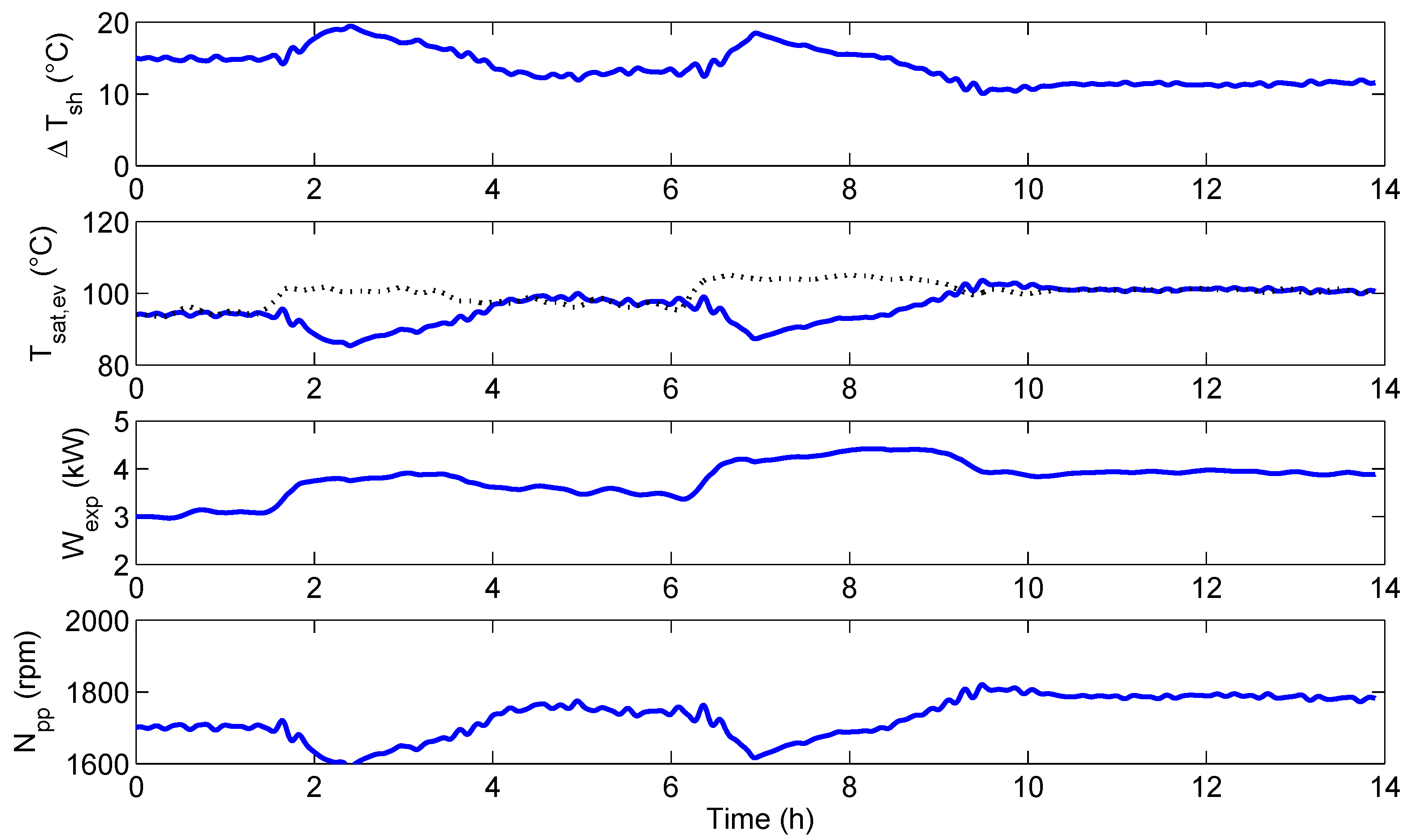
5.1. Constrained EPSAC-MPC Strategy
The control objective for EPSAC-MPC consists of tracking the setpoint generated by the optimizer (
Figure 3), while keeping the superheating above a desired threshold value to guarantee a safe operation. The control strategy must satisfy these conditions using only one degree of freedom (
i.e., pump speed
), while satisfying actuator constraints (
;
;
) and constraints at the process output (
C).
The EPSAC-MPC is designed with control horizon
and prediction horizons
,
. The ES optimizer is designed with tuning parameters:
,
,
,
and
. The results are depicted in
Figure 7, where two optimal evaporating temperatures are present, one computed using the ES algorithm (dashed red line) and the other (black circles) computed from correlation in Equation (4).
The ES algorithm is able to adapt properly to the heat source variation, maximizing the output power. Notice that in the time range between 250 and 300 s, the controller is not following the ES setpoint. The latter is due to the active constraint in superheating, which causes the controller to take actions in the pump to bring the system to a safer regime (i.e., C).
5.2. PI-Like Strategies
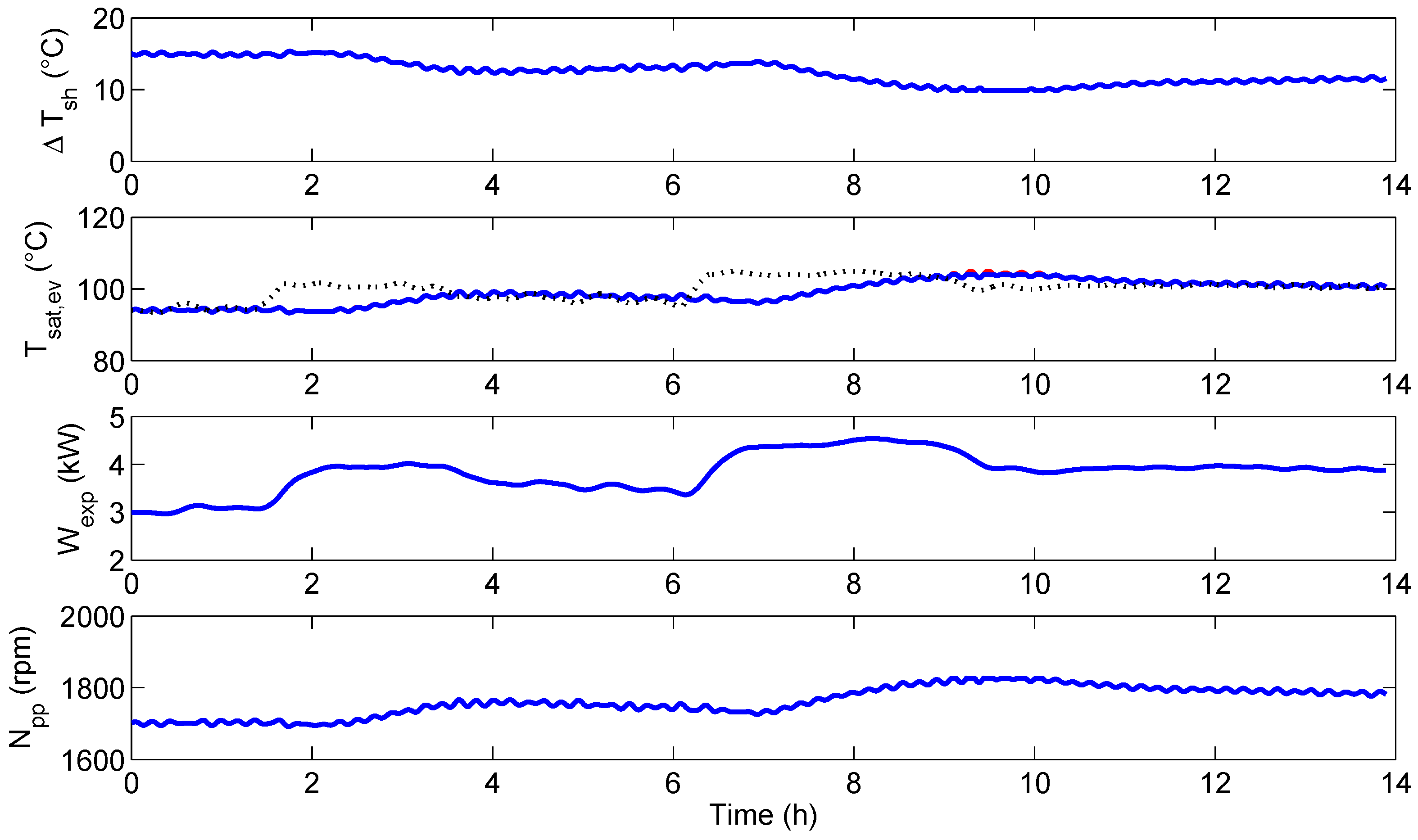
The performance of the MPC regulator is compared with two PI-like strategies.
Single PI strategy: a PI controller for evaporating temperature, , is used to track the reference given by the ES optimizer.
Switching PI strategy: this consists of using a PI controller, , to track the optimal evaporating temperature, unless superheating goes below the threshold value of C, in which case, a second PI controller for superheating, , with reference at C, is enabled, thus bringing the system back into a safer regime.
The results for the single PI strategy are depicted in
Figure 8. The ES optimizer (dashed red line) adapts the reference to the local PI controller,
, towards the optimal evaporating temperature,
, in order to maximize the output power. As the superheating is not controlled, the ORC unit is brought to hazardous working conditions characterized by a two-phase state (
i.e., gas and liquid phase) at the expander inlet as observed at time 250–300 s and 350–400 s.
The performance of the switching PI-like strategy is reported in
Figure 9. The
controller tracks the reference generated by the ES optimizer, unless the superheating value goes below a threshold value, in which case the
controller with reference at
C is enabled. The latter takes the system back to a safe operating condition, avoiding the two-phase state at the expander inlet.
Despite the adoption of two controllers, super-heating values below C are registered during operation from time 250–300 s. Furthermore, more aggressive control actions are imposed on the pump rotational speed compared to the MPC methodology.
In order to assess the capabilities of the proposed control strategies to maximize the ORC unit performance, the net energy generation is computed by integrating the net output power over the simulation time. As the single PI strategy is not able to ensure safety conditions, it is discarded from this comparison. Taking the switching PI as a reference (), the EPSAC-MPC strategy allows increasing the net energy production by . This is due to a better handling of the constraints, thus operating the system closer to the constraint for superheating while requiring a lower control effort (i.e., less power consumption in the pump).
5.3. Superheating Control Strategy
Many contributions available in the literature and most of approaches followed in industrial practice suggest the use of a controller that would simply maintain a constant superheating. It is therefore interesting to investigate its performance and to compare it to the approach proposed in this paper.
The PI controller in charge of regulating superheating is tuned, making a trade-off between diminishing the output variability (i.e., minimizing the tracking error) and the required control effort. The reference for the controller is set at C, in order to get an extra safety margin, thus avoiding superheating going below the desired minimum limit (i.e., C).
The PI controller is able to regulate the superheating level around the setpoint, respecting almost at all times the superheating safety limit of
C (
Figure 10). In terms of power production, it sometimes outperforms the ES with a low-level controller as observed from time 350–450 s, where, due to the active constraint, the controllers allow a larger tracking error in order to bring the system to a safer regime.
Although the controller for superheating is performing well, it requires more aggressive control actions, leading to a higher pump power consumption. The net energy output is thus reduced and lower compared to the proposed strategy using ES and a low-level controller. Computing the net energy produced, the PI superheating controller generates () more compared to the switching PI strategy, but () less if compared to the ES-MPC approach.
6. Guidelines for ES Tuning and the Stability Test
The perturbation-based extremum seeking algorithm includes five parameters that should be tuned: the cut frequencies of the low and high pass filters, the integrator gain k, the amplitude γ and frequency ω of the dither signal. This section is an attempt to provide guidelines for the ES parametrization.
Selecting the dither frequency
ω is a trade-off between the speed of convergence and precision. The dither signal should vary slowly enough for the plant to settle, thus preventing the plant dynamics from interfering with the peak seeking scheme [
32]. On the other hand, increasing the dither frequency allows the integrator gain to be increased proportionally, while retaining the same domain of attraction [
36]. As a rule of thumb, the dither frequency should be slower than the open-loop dynamics of the plant to obtain a useful signal to noise ratio (SNR) at the input of the ES scheme. It is worth mentioning that although the exact bandwidth of the plant is unknown, the low-order model used for MPC can be used to determine a suitable value for
ω.
The value of the integrator gain
k is a trade-off between the speed of convergence, precision and stability. A higher gain results in faster convergence, but the influence of any noise present in the output of the low pass filter becomes more dominant. Furthermore, there is an upper limit on the integrator gain with respect to the stability of the adaptation loop. Increasing the integrator beyond this value will render the adaptation unstable [
37].
The amplitude of the dither signal is a trade-off between accuracy and precision. A large
γ results in a larger offset with respect to the optimal point [
36]. On the other hand, a smaller
γ leads to a reduction in precision, as the decrease in the amplitude of the modulated gradient brings a deterioration of the SNR at the input of the ES scheme.
In order to investigate the stability and robustness of the presented adaptive control strategy, a second test is performed including measurement noise, as well as large variations in the heat source mass flow rate
. The heat source and heat sink profiles used for the test are depicted in
Figure 11.
In
Figure 12, the performance of the proposed constrained adaptive strategy is tested when using a dither signal amplitude of
. The algorithm faces some problems to quickly converge to the optimal evaporating temperature, represented by the dashed black line obtained from Equation (4). This is due to the low SNR obtained using such a low amplitude of the dither signal. The system, although stable, is not performing optimally as concluded by observing the ‘high’ level of superheating obtained and the power generated.
A new experiment is performed using the same external conditions, but increasing the dither signal amplitude by two,
i.e.,
. By increasing the value for
γ, the SNR is increased, thus making it possible for the algorithm to quickly converge close to the optimal value, as reported in
Figure 13. Attention has to be paid to avoid increasing this value unnecessarily, as a large
γ could result in a larger offset with respect to the optimal point [
36].


 ,
, 


