Article

Thermodynamic Simulation on the Performance of Twin Screw Expander Applied in Geothermal Power Generation

School of Mechanical Engineering, Shanghai Jiao Tong University, Shanghai 200240, China
*
Author to whom correspondence should be addressed.
Energies 2016, 9(9), 694; https://doi.org/10.3390/en9090694
Submission received: 23 June 2016 / Revised: 1 August 2016 / Accepted: 23 August 2016 / Published: 31 August 2016

Abstract

:
A three-dimensional (3D) geometry model of twin screw expander has been developed in this paper to measure and analyze geometric parameters such as groove volume, suction port area, and leakage area, which can be described as functions of rotation angle of male rotor. Taking the suction loss, leakage loss, and real gas effect into consideration, a thermodynamic model is developed using continuity and energy conservation equation. The developed model is verified by comparing predicted results of power output and internal efficiency with experimental data. Based on the model, the relationship between mass flow rate through inlet port and leakage path with rotation angle of male rotor as well as effects of the inlet parameter and operating parameter on the performance of the expander are analyzed.

1. Introduction

Owing to energy shortage, concerns over environmental issues, as well as interest in power recovery from geothermal energy and industrial waste heat have increased all over the world. Currently, Organic Rankine Cycle (ORC) system, trilateral flash cycle system, and flash steam cycle system are widely applied in geothermal power generation. The twin screw expander is a core component of the system because of its simple construction, high overall efficiency, and the ability to accept two-phase liquid-vapor mixtures. Theoretical analysis and computer simulation for investigating the geometry model and thermodynamic model of screw expander would be beneficial for optimizing its performance.
Geometric modelling is the foundation of one-dimensional thermodynamic modelling and the three-dimensional Computational Fluid Dynamics (CFD) analysis of screw expander, and computer aided design could provide benefits for accurate identification of geometric parameters. Buckney et al. [1] calculated geometric parameters of screw compressor such as volume, gradient and cross-section, leakage flow, and blow-hole areas by 3D Computer Aided Design (CAD). The results were compared with that generated by usual geometric calculation procedures, from which improvement in the accuracy can be demonstrated. A lot of research on the numerical study of screw compressors has been done over the years. Xing and Wu [2] built a new mathematical model to calculate the indicator diagram of twin screw refrigeration compressor, taking heat transfer between oil and gas and leakage loss into account. They also developed the key technology for screw compressor including profile design method, cutter design, and soft package of SCCAD [3,4]. Kovacevic, Smith, and Stosic [5,6,7] introduced the geometric characteristic, design philosophy and design example of the screw compressor and screw expander, and the performance of screw compressors was calculated based on one-dimensional (1D) and 3D computer models. Seshaiah et al. [8] carried out mathematical analysis of the oil injected twin-screw compressor on the basis of the laws of perfect gas and standard thermodynamic relations to analyze the effect of certain compressor operating and design parameters on the performance. They concluded that inter-lobe clearance and rotational speed greatly affect the efficiency and P-V diagram. Zamfirescu et al. [9] experimentally studied the performance of oil free two phase ammonia(water) screw compressor and proposed a non-homogeneous model considering the heat and mass transfer phenomena in the compressor. Based on three conservation equations and the state equation of homogenous NH3/H2O mixture, Zaytsev et al. [10,11] presented a one-dimensional leakage flow model for two-phase ammonia-water twin screw compressors, which took viscous and acceleration forces into account. Chamoun et al. [12] presented a twin screw compressor model including a water injection system. The effect of water injection, external compression ratio, and rotational speed on the compressor’s behavior were also analyzed. Smith et al. [13,14,15] compared the trilateral flash cycle (TFC) with Rankine cycle by means of theoretical and experimental analysis and showed the viability of the TFC system. Öhman et al. [16] presented the experimental findings in a series of laboratory tests on a semihermetic Lysholm Turbine operating with R134a with superheated, saturated, and wet inlet gas conditions. The conclusions were that Lysholm Turbines were well suited for low temperature power generation, but the further research of performance during two-phase conditions was required. Papes et al. [17] presented the CFD analysis of a twin screw expander in an ORC system with refrigerant R245fa and obtained the pressure-volume diagram, mass flow rates, and power output for different pressure ratios. They found that additional injection of the working fluid could increase the generated power and avoid over-expansion. Kovacevic et al. [18] built the CFD model of an oil free twin screw air expander to analyze pressure-angle diagrams, mass flow rates and expansion power at different operating conditions and concluded that correct design of the high pressure port is vital and leakage flows have a significant effect on screw expander efficiency. Hütker et al. [19,20] described the technical and physical processes within a screw expander by using experiments as well as thermodynamic simulations on the basis of a multi-chamber model. They also investigated the effect of variation of the geometric parameters and system parameters on the operating behavior of the screw motor. It was shown that the primary loss mechanisms of a screw expander are the inlet throttling during chamber filling as well as the gap mass flows in the expansion start range.
There are a few experimental and theoretical researches on the twin screw expander. However, CFD model is too complicated for engineering design. Theoretical investigation on the leakage of screw expander is not sufficient. A new geometry-based thermodynamic analysis method is presented in this paper. A 3D geometry model of twin screw expander is developed, which consists of male and female rotors and of inlet and outlet ports. Some geometric parameters such as groove volume, suction port area, and leakage area as a function of rotation angle of male rotor could be measured with the geometry model. Then the mathematical model of the screw expander is established to research the influence of inlet pressure, mass flow rate, and rotate speed on the leakage, internal efficiency, and power output. The model is verified by comparing predicted results of power output and internal efficiency with experimental data.

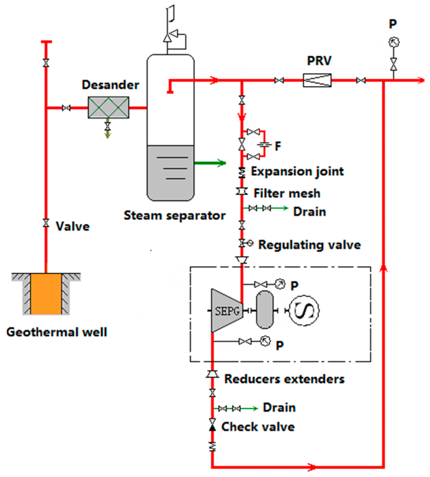
2. Geothermal Power Projects in China

In the early 1970s, geothermal development was becoming a hot trend in China. Seven low-temperature geothermal power plants had been established all over the country using flash evaporation or binary cycle, but the generated output of one unit was less than 300 kW and the generating efficiency was low.
High temperature geothermal power generation began to develop in Tibet in the middle 1970s. From 1977 to 1991, nine steam turbine generator units were installed, and the total installed capacity reached 25.18 MW in YangBaJing geothermal power plant and it is a successful example of geothermal development in China. Up to 2013, YangBaJing geothermal power plant has a total output of 2.8 billion kilowatt hours with stable power output, high load rate, and an average utilization of 68%.
Screw expander power generation unit was applied in Tibet firstly in 2008. Two screw expander power generation units were installed at YangBaJing geothermal power plant with an output power of 1000 kW. The picture of the second screw expander generating unit is shown in Figure 1. This generating unit produces real power of 800 kW with actual operation parameters of inlet pressure of 0.39 MPa, outlet pressure of 0.09 MPa, and the mixture flow rate of 22 t/h.
Figure 2 shows a schematic of the screw expander power generation unit. Steam water mixture from the geothermal well flows through the desander, and then flows into the steam separator where vapor is separated from water. This vapor flows through the twin screw expander and is expanded to generate mechanical work to drive the electrical generator.
The pressure and temperature of vapor at the expander inlet and outlet are measured by the sensors, and the vapor flow rate is measured by flow meter. Then, the internal efficiency and power output of the screw expander could be calculated and compared with simulated values.
Screw expander is a core component of geothermal power generation system, and a detailed analysis of its working process is conducive to promote the efficiency of the system. The geometry model and thermodynamic model of twin screw expander driven by saturated steam are presented below, which are the foundation of researching a screw expander driven by two-phase geothermal sources.

3. Geometry Model

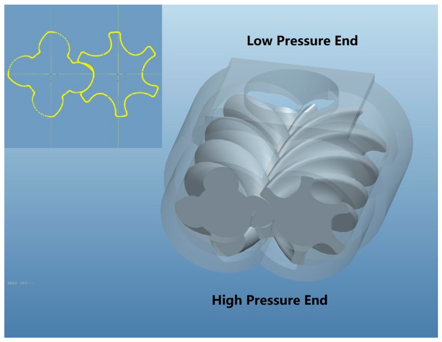
3.1. 3D Model and Basic Parameters
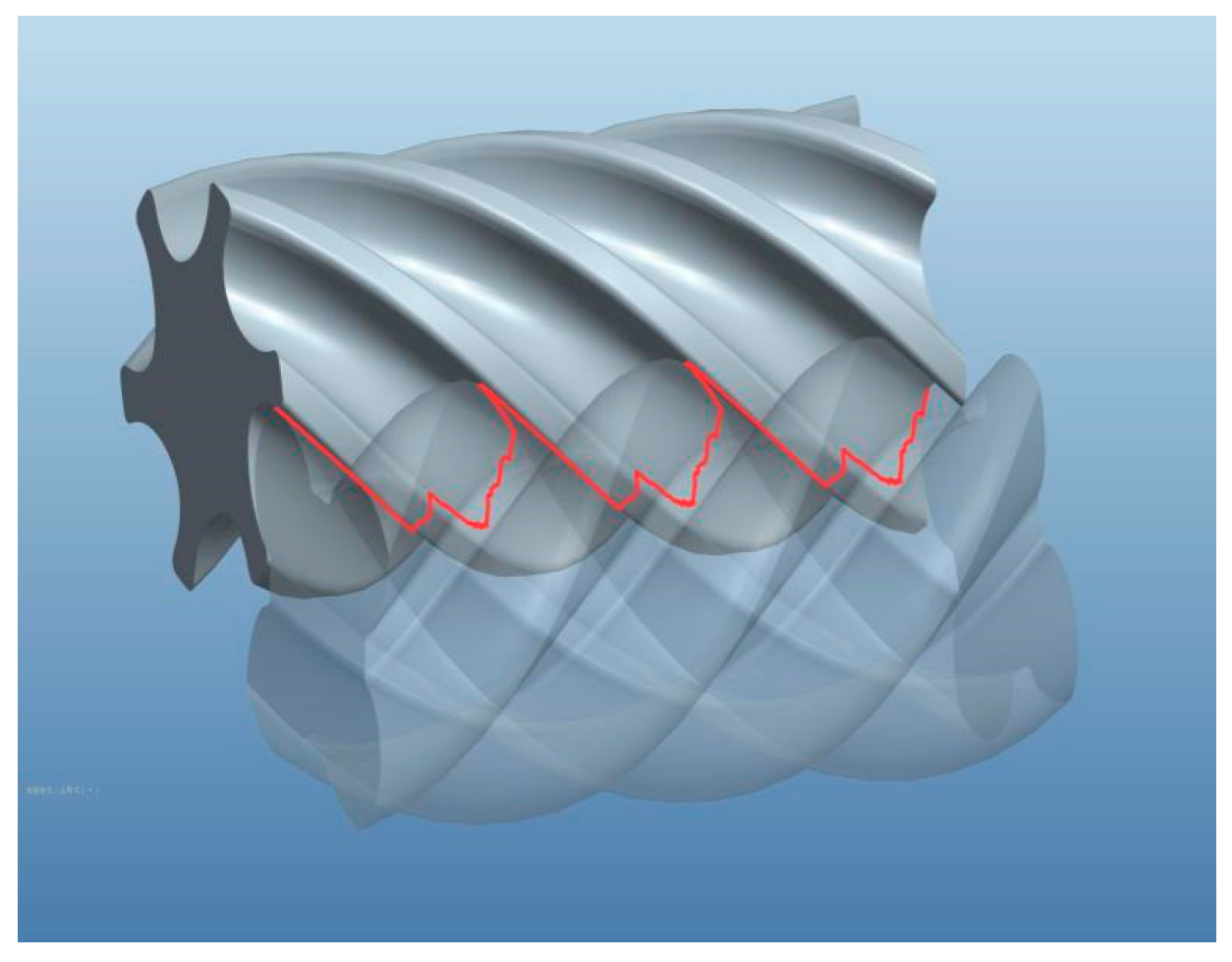
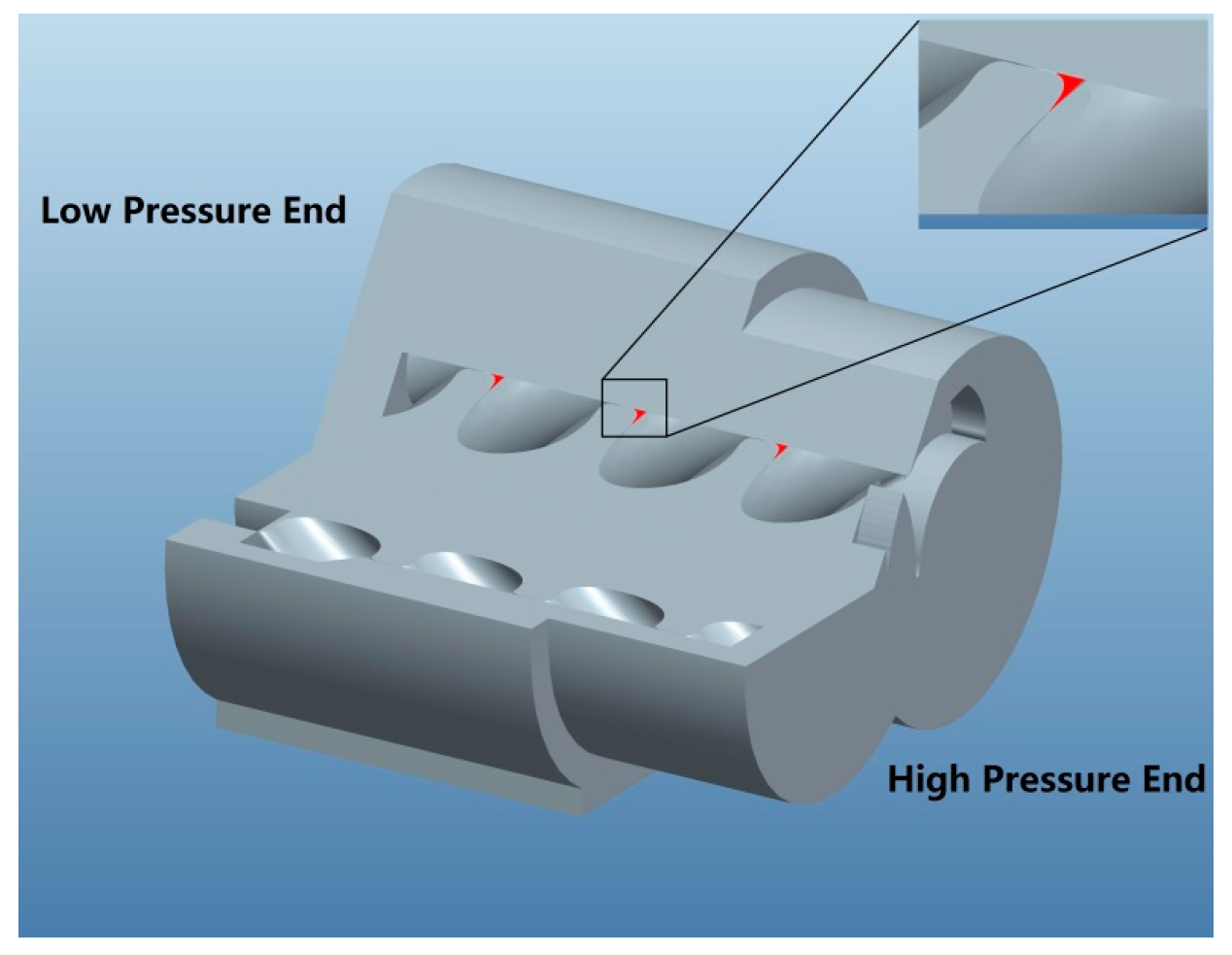
The main components of twin screw expander are a pair of meshing helical rotors, bearings, seals and a fixed casing. With the reversing rotation of rotors, each pair of meshing teeth complete one work cycle in succession. The working chamber formed by a pair of meshing teeth and its surrounding case is called the primitive volume, and the dimension and position of the primitive volume vary with time. The research on the expander can be simplified as the research on the primitive volume. Rotor profile is shown on the top left corner in Figure 3. A 3D geometry model of the twin screw expander could be built based on rotor profile and the basic geometric parameters which are listed in Table 1.
A new working chamber forms and is connected with the inlet port when the rotors rotate in opposite directions, and the mass of working fluid increases with increasing chamber volume. As rotation continues, the working chamber is cut off from its connection with the inlet port, the suction process ends and the expansion process begins while the chamber volume continuously increases. During expansion process, the increase of chamber volume leads to decrease of pressure of the trapped fluid. When the volume reaches a maximum, the working chamber connects to the discharge port and the discharge process begins. Suction and discharge processes are decided by the shape and position of inlet and outlet ports which is depended on the inner volume ratio Ɛ, Ɛ is defined by:
ε = V max V i
where, Vmax is only determined by geometric parameters of screw expander. A larger inner volume ratio leads to a shorter filling period and a greater inner pressure ratio, accounting for a more serious throttling effect during suction. Figure 4 shows the relationship between working chamber volume as well as inlet port area with male rotor angular position under different inner volume ratios. The area between male and female tooth at the inlet port A(θ) could be measured by a geometric model and the chamber volume V(θ) could be calculated by the following formula:
0 < θ 300   V ( θ ) = 0 θ L β A ( t ) d t 300 < θ 560   V ( θ ) = θ 300 θ L β A ( t ) d t 560 < θ 860   V ( θ ) = θ 300 560 L β A ( t ) d t

3.2. Leakage Paths

As a result of the existence of machining tolerance and thermal expansion, clearances exist between lobes, and between rotors and the casing. The pressure difference induces leakage of working fluid, in turn affecting the performance of expander.
The main leakage paths in twin screw expander are leakage through inter lobe clearance, rotor tip-housing clearance, clearance of inlet end face, and blowhole. Leakage mass through inter lobe clearance will go directly into the discharge chambers. The contact line and blowhole are shown in Figure 5 and Figure 6 separately. The leakage paths area which changes with male rotor angular position is measured and calculated by geometric model and the results are presented in Figure 7. The coordinates of the contact points can be got in PROE, so the length of contact line can be measured directly. The blowhole will be formed among the top point, the contacting point between the cusp and the male rotor, and the contacting point between the cusp and the female rotor. The area of the blowhole can also be measured in PROE. The rotor tip leakage includes female rotor and male rotor, and the sealing lines are circular helix. The length of rotor tip sealing line can be calculated by the calculation formula of spiral length. The sealing line length of inlet end face leakage can also be measured for each male rotor angular position in PROE.
The leakage flow rate depends on leakage path area, flow coefficient, pressure, and temperature difference between the working chamber and its adjacent chambers. As can be seen from Figure 7, leakage path area through rotor tip-housing clearance is largest due to the large size of screw expander. The blow hole is the smallest and once formed it will remain the same until disappear.

4. Thermodynamic Model

4.1. Assumptions

In order to simplify the calculation, the following assumptions are made to establish the mathematical model of the working process:
1.
State parameters of the steam in a working chamber are uniform.
2.
Heat transfer between working chamber and the surroundings is negligible and working fluid leak through clearance is isentropic.
3.
Discharge process is isobaric.

4.2. Governing Equations

The differential equations of pressure, temperature, and mass with respect to male rotor angle can be deduced by using the basic formula of thermodynamics, the conservation equation of energy and mass equations of variable mass system. The expressions are as follows:
d P d θ = c P ( P v ) T d v d θ + ( P T ) v 1 m [ d m i d θ ( h i h ) ] c v
d T d θ = T ( P T ) v d v d θ + 1 m [ d m i d θ ( h i h ) ] c v
d m d θ = d m i d θ d m o d θ
With the data of working chamber volume, inlet area and leakage paths area as well as complementary equation, Equations (3)–(5) can be solved by fourth order Runge-Kutta method.

4.3. State Equation of Steam

The state of working fluid should be described by state equation and ideal gas equation of state is not suitable for steam. For the steam temperature under critical temperature and low pressure, the two coefficients of the Virial equation can satisfy the calculation accuracy. The general expression of Virial equation is as follows:
P v R g T = 1 + B ( T ) v + C ( T ) v + D ( T ) v
where B(T), C(T), and D(T) are Virial coefficients and can be expressed as functions of temperature.

4.4. Suction Steam Mass and Leakage Mass

The leakage flow path can be simulated as an isentropic convergent nozzle (Ziwen 2000):
d m l e a d θ = { C A l P 1 ω 2 k ( k 1 ) R g T 1 [ ( P 2 P 1 ) 2 k ( P 2 P 1 ) k + 1 k ]       ( 2 k + 1 ) k k 1 P 2 P 1 1 C A l P 1 ω k ( k 1 ) R g ( 2 k + 1 ) k + 1 k 1                   0 P 2 P 1 ( 2 k + 1 ) k k 1
where, C is the flow coefficient and is decided by operation condition and the type of leakage path.
Inducted steam mass is determined by inlet port area and pressure difference between the working chamber and inlet pipe, and is given as following:
d m i d θ = ρ i A i C i 2 ( h i h ) ω
The selection of inlet flow coefficient should make sure that simulated mass flow rate is equal or close to the actual mass flow rate of screw expander.

5. Results and Discussion

5.1. Model Verification

The twin screw expander used in this paper has been put into practical application in YangBaJing geothermal power plant and some factories to generate electricity. In this paper, choosing five sets of experimental data that recorded in YangBaJing geothermal power plant (Case 1 and 2), Shanxi Longmen Iron and Steel Company Limited (Case 3), SINOPEC Maoming Company (Case 4), and Yongfeng Steel Company Limited (Case 5) to validate the accuracy of the model. The operation conditions of five cases are listed in Table 2.
The accuracy of the model can be evaluated by the comparison of internal efficiency, power output and mass flow rate. The internal efficiency of the twin screw expander is the ratio of the indicated expansion work output to the isentropic expansion work output, and is given as following:
η i = W ind W iso
The isentropic expansion work output is given by:
W iso = m c ( h i h o ' )
where mc is the mass of the working fluid in the control working chamber, hi is the specific enthalpy of the working fluid at the inlet port, h o ' is the specific enthalpy of the working fluid at the outlet port during the isentropic process.
The simulated indicated work is represented by the area of the indicated P-V diagram:
W ind = V d P
The experimental indicated work is calculated as:
W inde = m c ( h i h o )
where ho is the specific enthalpy of the working fluid at the outlet port. mc is the mass of vapor suctioned into the primitive volume, and it can be calculated by the equation below:
m c = 60 Q n z 1
where z1 is the number of teeth on the male rotor, and n is the number of revolutions per minute of the male rotor, and Q is inlet mass flow rate.
The power output of the expander can be computed by using the indicated work in a single working chamber:
P ind = W ind z 1 n 60
Comparison of power output, mass flow rate, and internal efficiency between model prediction and experimental data are shown in Table 3. The mean deviations of the simulated from the measured values are 4.68% for power Pind, 3.62% for mass flow rate mt and 4.66% for internal efficiency ƞ. The results prove that the model has good accuracy.

5.2. Simulation Results

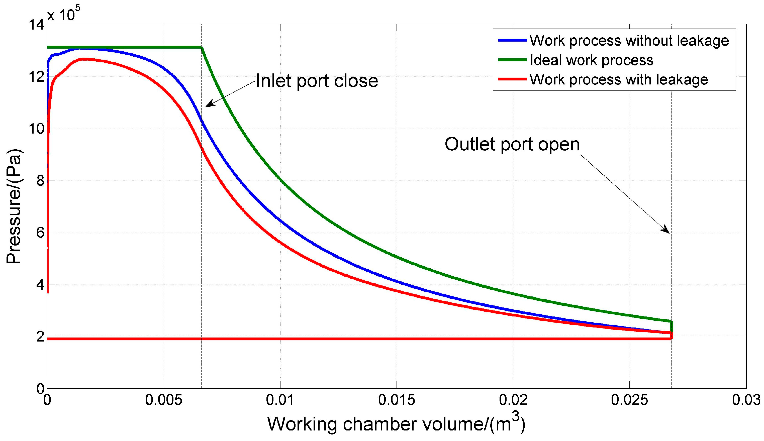
5.2.1. Comparison of the Ideal and Actual Working Process

P-V diagrams of case 5 for ideal and simulated work processes are presented in Figure 8. At the beginning of suction process, the area between two lobes increases from zero and is smaller than the area of inlet port, thus resulting in throttling effect and pressure drop. Leakage between working chamber and adjacent chambers will aggravate the throttling losses. With the rotation of the rotor, decrease of the inlet area in conjunction with increase of the working chamber volume lead to pre-expansion during suction process. Leakage has a significant effect on the performance of twin screw expander. At the later period of expansion, the pressure in working chamber is low and the inflow exceeds outflow, therefore the pressure in the working chamber is higher when taking leakage into consideration. A serious inflow can even cause the pressure of the chamber to rise at the final expansion phase.
The relationship between the ideal and simulated working fluid mass with male rotor angle is depicted in Figure 9. The actual mass in the chamber is lower than the ideal work process at the end of suction as a consequence of leakage and throttling effect. The mass in the working chamber decreases with the increase of rotation angle at the beginning of expansion and then increases. The reason is that the mass leaking out of the chamber is more at the initial expansion stage and it is just opposite at the end of expansion.

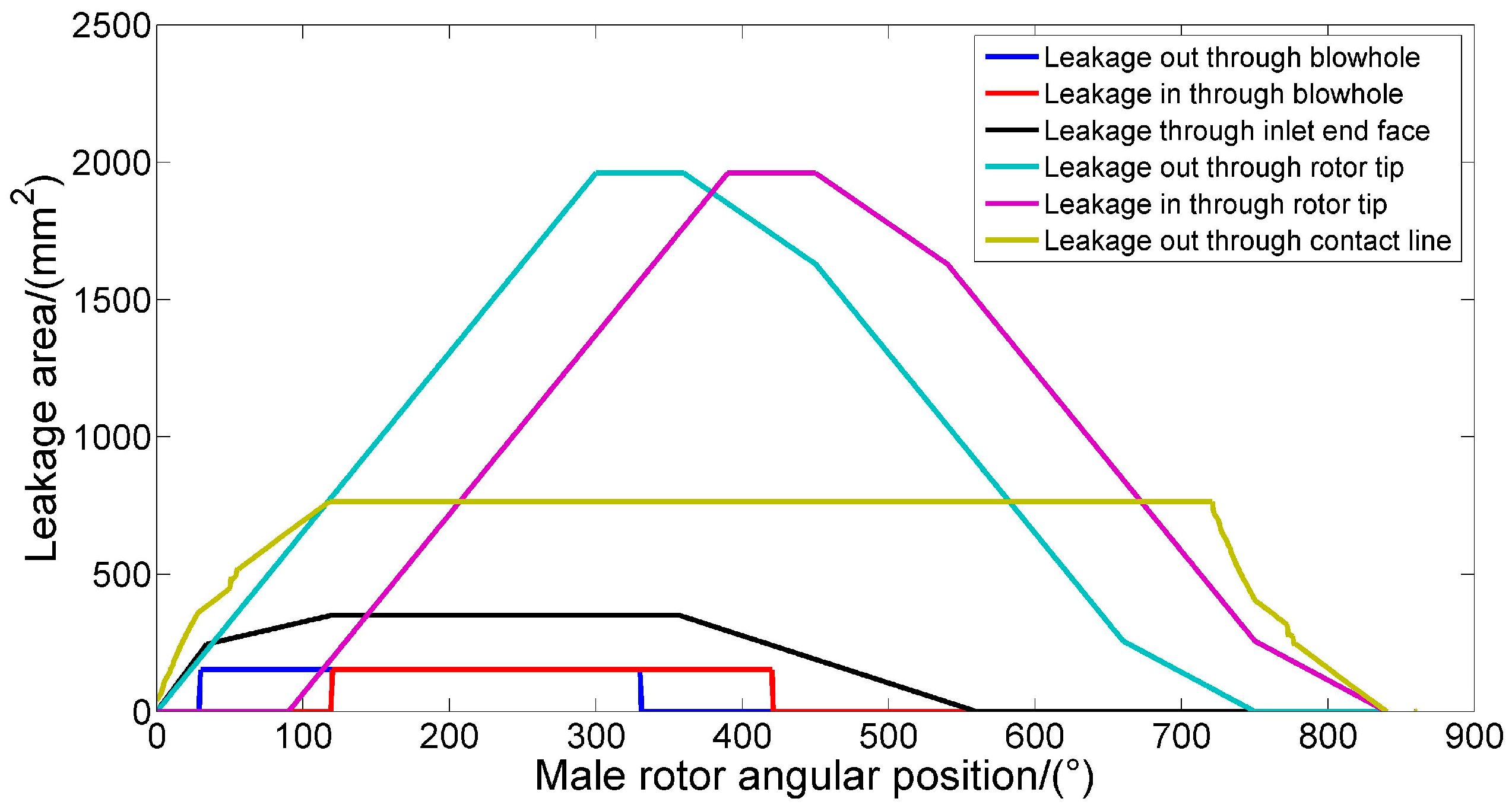
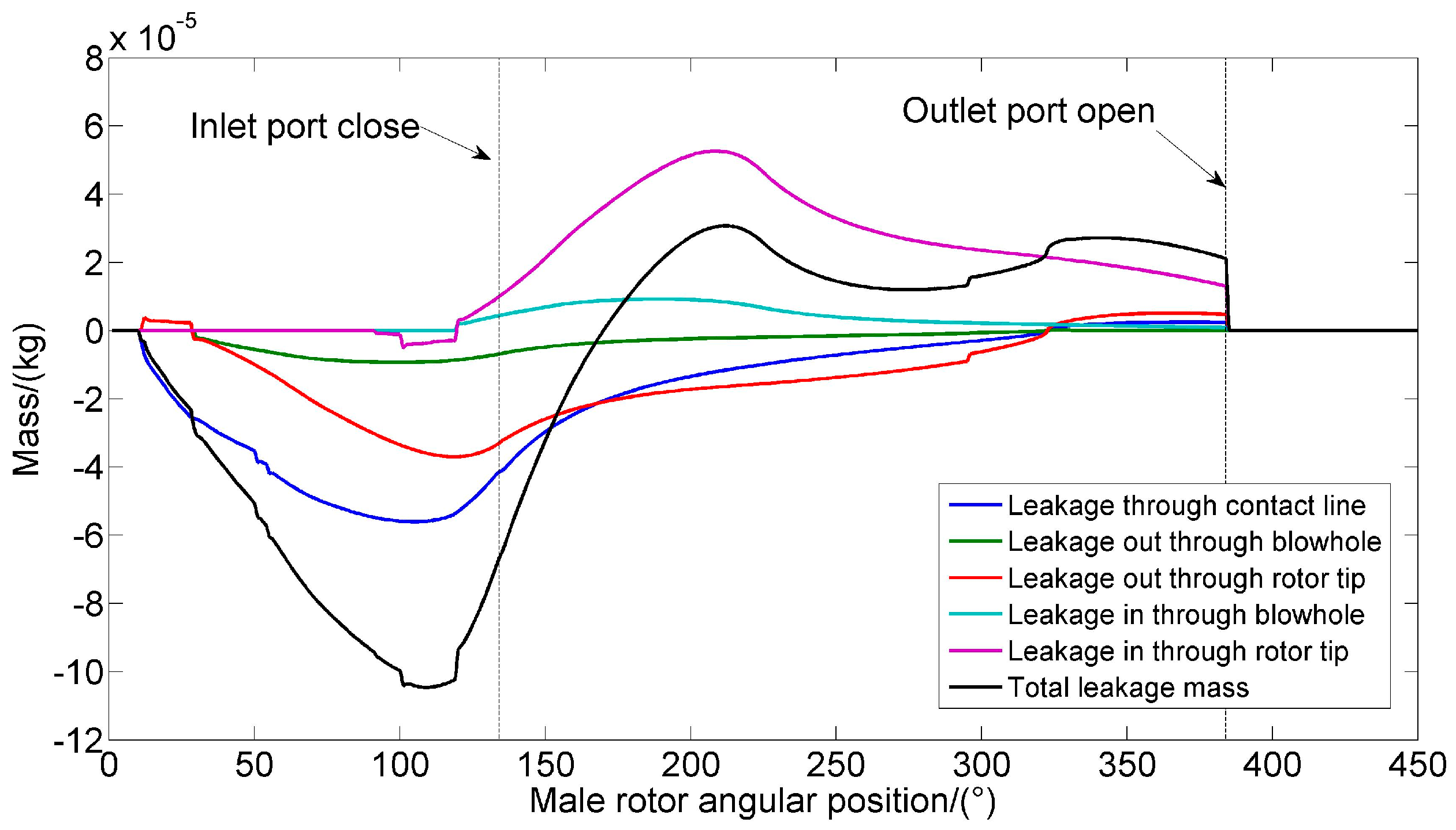
5.2.2. Comparison of Leakage through Different Paths

Simulated leakage mass over the rotation angle of the male rotor is presented in Figure 10. Leakage into or out of the control volume are indicated by positive and negative of the mass value. During the suction process and early stage of expansion process, leakage through contact line is predominant because of the large pressure difference between working chamber and discharge chamber. In the expansion process, the rotor tip leakage becomes a major leak path on account of the increasing leakage area. With the proceed of rotating, the amount of leakage gradually recedes because of the decrease of the chamber pressure. Considering that the blowhole area and the pressure difference of adjacent chamber are small, leakage through blow hole has a little impact on the efficiency of screw expander. The total leakage mass is the sum of leakage through four leakage paths. During the suction process and early stage of expansion process, leakage of the working fluid in the control volume is outward on the whole, and the leakage mass increases until reaching maximum at 100° and then reduces to zero. In the later stage of expansion, leakage of the working fluid is inward on the whole. The influence of thermal deformation, thermal expansion and centrifugal force on leakage mass is not taken into consideration and needs further study.

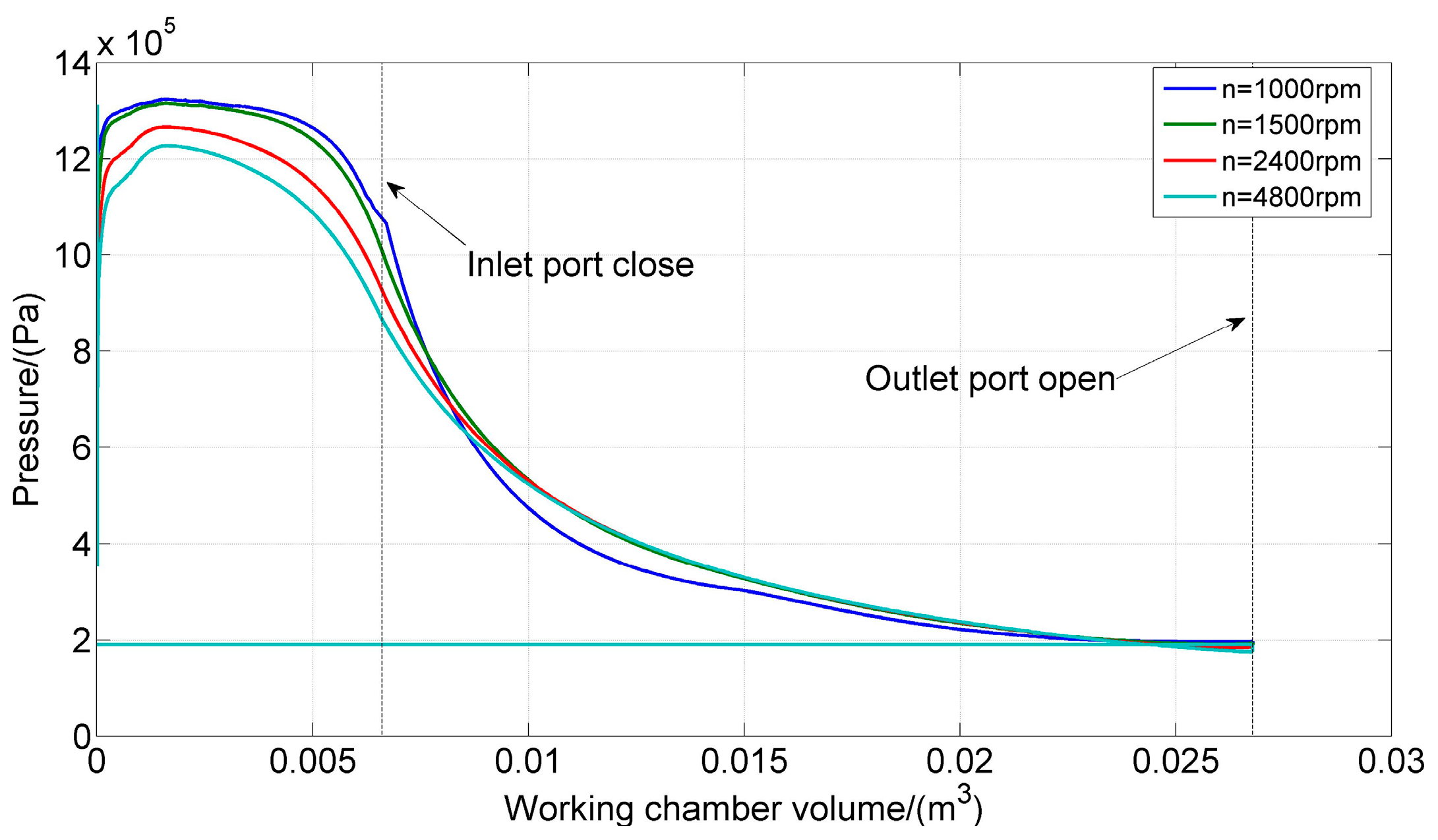
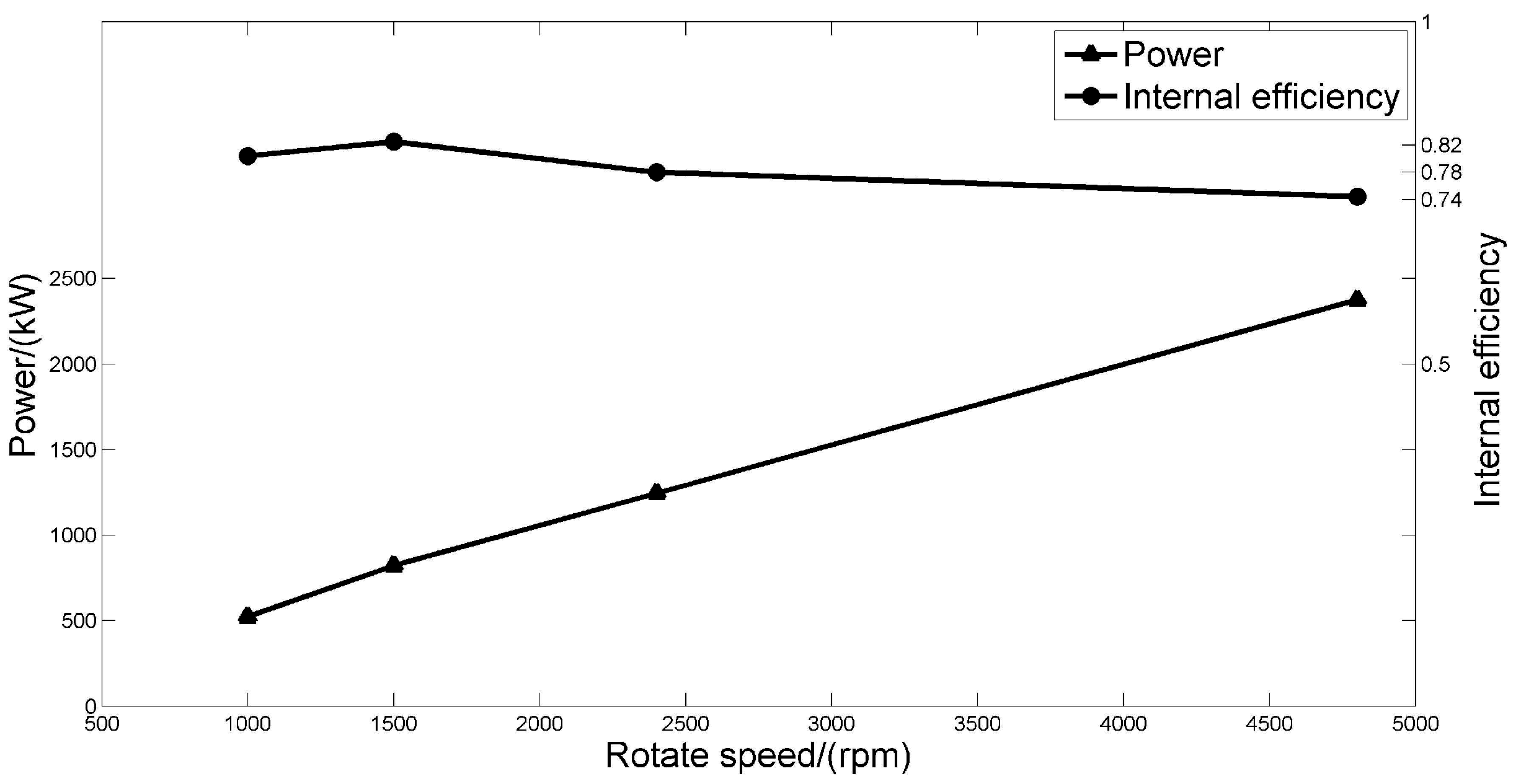
5.2.3. The Effect of Inlet Pressure and Rotational Speed on the Performance of Expander

As shown in Figure 11, rotate speed also has an impact on the performance of screw expander. A higher rotate speed means a larger inlet mass flow rate and power output, but not always the higher the better. Although increasing rotate speed can reduce leakage losses, but inlet pressure drop losses and throttling losses increase simultaneously, and the pressure in the chamber will be lower at the end of suction process. For selected geometric parameters and operation conditions, the relationship between power and internal efficiency of twin screw expander with rotate speed are presented in Figure 12. The power increases with the speed while the internal efficiency increases as well until reaching a maximum value and then reduces slightly.
Figure 13 shows the P-V diagram of different inlet pressure under fixed rotate speed, inlet end angle, and discharge pressure. Choosing a high inlet pressure will result in the increase of throttling losses, leakage losses, and pressure drop in the suction process. Consequently, the pre-expansion will take place in advance. As is shown in Figure 14, when the internal specific volume equals to the built-in volume ratio determined by geometric parameters, screw expander has the highest internal efficiency. If the inlet pressure is too high for a given set of operating conditions and geometric parameters, under-expansion will happen. On the contrary, if the inlet pressure is too low, over-expansion will happen. The above-mentioned two cases will cause the decrease of the efficiency of the twin screw expander. The power increase with increasing inlet pressure but the upward trend is slow at high pressure.

6. Conclusions

Geometry modelling and thermodynamic modelling of twin screw expanders have been established and validated. The maximum simulation error of power, mass flow rate and internal efficiency are 5.83%, 5.56%, and 5.84% separately. Using the model, mass flow rate through inlet port and leakage paths as a function of rotation angle of male rotor as well as the influence of inlet pressure and rotate speed on the performance of the expander are analyzed. The following conclusions were obtained from the results of the investigation:
(1)
Throttling losses, pressure drop losses, and leakage losses during the working process are the main influence for the internal efficiency of twin screw expander.
(2)
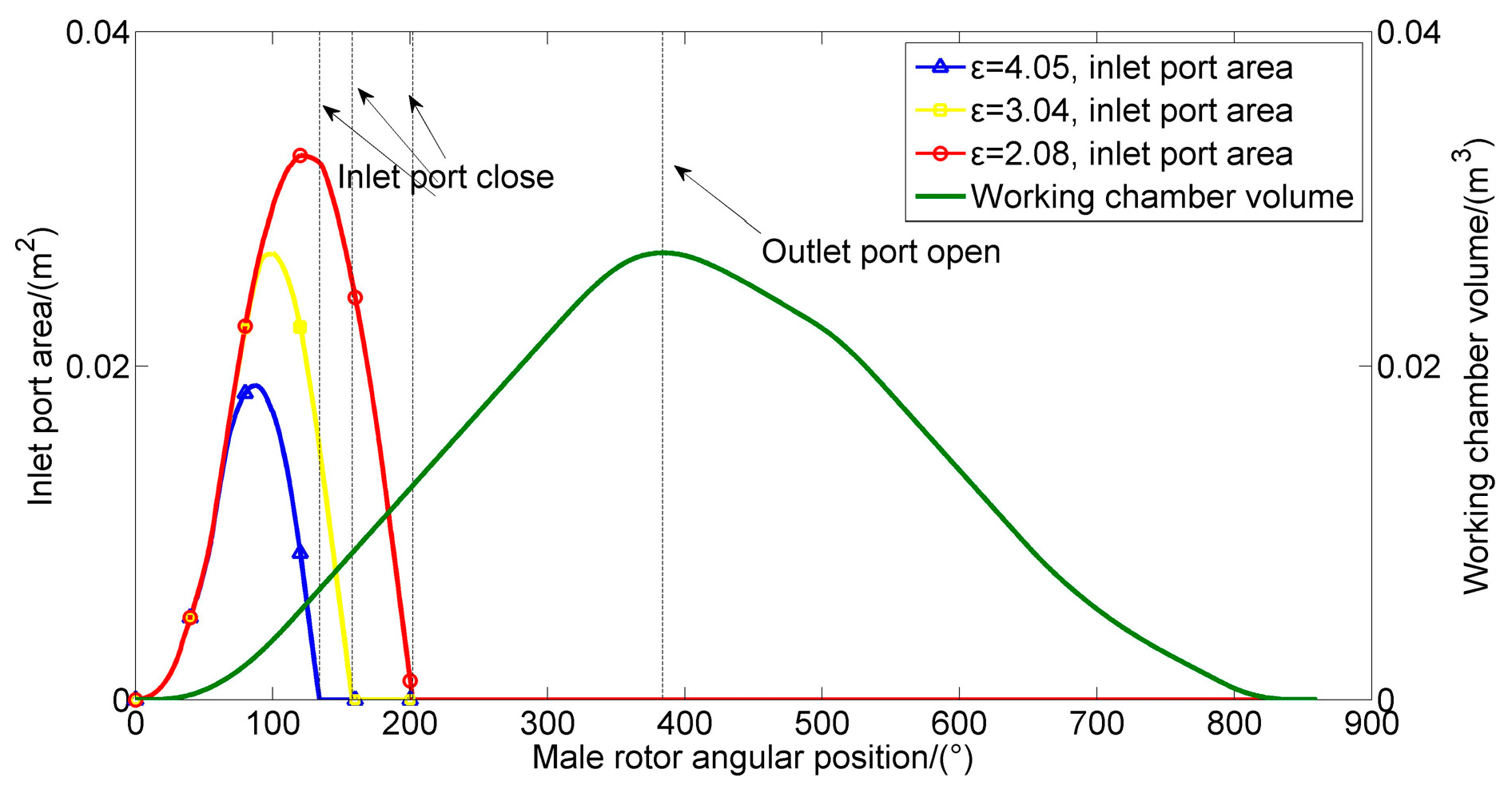
The mass in the chamber decreases with the increase of rotation angle at the beginning of expansion and then increases until the discharge process starts. Because of the large leakage area, leakage through rotor tip-housing clearance is predominant.
(3)
Leakage in the suction process and the early stage of expansion process are most serious, while the contact line and the rotor tip are two main leakage paths. Large pressure difference is the cause of the serious leakage of the former, and the long sealing line of the rotor tip-housing clearance contribute to the serious leakage of the latter. The increase of inlet pressure and the decrease of the rotational speed will increase the mass of leakage.
(4)
The throttling losses and pressure drop losses increase with the increasing rotate speed and inlet pressure, and with higher inlet pressure, the pre-expansion begins earlier. Power increases with the inlet pressure and rotate speed but has a slow ascending trend at high pressure.
Choosing appropriate operating parameters is extremely important for the twin screw expander to achieve the highest efficiency. The geometry model and thermodynamic model presented in this paper will contribute to optimizing the design of twin screw expander.

Author Contributions

Yu Yuefeng conceived and designed the study; Yu Yuefeng performed the field experiments; Qi Yuanqu built the simulation model and analyzed the data; Qi Yuanqu wrote the paper.

Conflicts of Interest

The authors declare no conflict of interest.

Abbreviations

The following abbreviations are used in this manuscript:
Vspecific volume, m3/kg
Vivolume of working space at the end of inlet, m3
Vmaxthe maximal volume, m3
Ppressure, Pa
Pindpower, KW
Ttemperature, K
Woutput work, J/kg
mmass of steam, kg
cpspecific heat of steam at constant pressure, J/(kg·K)
cvspecific heat of gas at constant volume, J/(kg·K)
hspecific enthalpy, J/kg
θmale rotor rotation angle, °
Aleffective area of leakage paths, m2
Aicross sectional area of inlet port, m2
Vvolume, m3
Rggas constant, J/(mol·K)
Cflow coefficient,
Lrotor length, m
Kratio of specific heats,
ωmale rotor rotation speed, rpm
ρdensity of steam, kg/m3
βwrap angle of male rotor, °
ƞiinternal efficiency,
Subscript
Isteam into the control volume
Osteam into the control volume
1high pressure zone
2low pressure zone

References

  1. Buckney, D.; Kovacevic, A.; Mujic, E.; Stosic, N. Some aspects of estimating geometric characteristics of screw compressors. In Proceedings of the International Compressor Engineering Conference, Purdue University, West Lafayette, IN, USA, 14–15 July 2012.
  2. Wu, H.; Xing, Z.; Shu, P. Theoretical and experimental investigation on working process of screw refrigeration compressor with R134a. J. Xi’an Jiaotong Univ. 2004, 35, 488–499. [Google Scholar]
  3. Xing, Z.; Wu, H.; Shu, P. Research and development on design theory and key technology of screw compressors. J. Xi’an Jiaotong Univ. 2007, 41, 756–763. [Google Scholar]
  4. Xing, Z. Screw Compressor-Theory, Design and Application; China Machine Press: Beijing, China, 2000. [Google Scholar]
  5. Kovacevic, A.; Stosic, N.; Smith, I. Screw Compressors: Three Dimensional Computational Fluid Dynamics and Solid Fluid Interaction; Springer Science & Business Media: New York, NY, USA, 2007. [Google Scholar]
  6. Smith, I.; Stosic, N.; Kovacevic, A. Power Recovery From Low Grade Heat by Means of Screw Expanders; Elsevier: Amsterdam, The Netherlands, 2014. [Google Scholar]
  7. Stosic, N.; Smith, I.; Kovacevic, A. Screw Compressors: Mathematical Modelling and Performance Calculation; Springer Science & Business Media: New York, NY, USA, 2005. [Google Scholar]
  8. Seshaiah, N.; Subrata, K.; Sahoo, R.; Sarangi, S.K. Mathematical modeling of the working cycle of oil injected rotary twin screw compressor. Appl. Therm. Eng. 2007, 27, 145–155. [Google Scholar] [CrossRef]
  9. Zamfirescu, C.; Nannan, N.; Marin, M.; Infante Ferreira, C.A. Oil Free Two Phase Ammonia (Water) Compressor; Report K-336 NOVEM-BSE-NEO; TUDelft: Delft, The Netherlands, 2004. [Google Scholar]
  10. Zaytsev, D.; Ferreira, C. Aspects of two-phase flow screw compressor modeling part I: Leakage flow and rotor tip friction. In Proceedings of the International Compressor Engineering Conference, Purdue University, West Lafayette, IN, USA, 25–28 July 2000.
  11. Zaytsev, D.; Ferreira, C. Aspects of two-phase flow screw compressor modeling part II: Friction between rotors. In Proceedings of the International Compressor Engineering Conference, Purdue University, West Lafayette, IN, USA, 25–28 July 2000.
  12. Chamoun, M.; Rulliere, R.; Haberschill, P.; Peureux, J. Modelica-based modeling and simulation of a twin screw compressor for heat pump applications. Appl. Therm. Eng. 2013, 58, 479–489. [Google Scholar] [CrossRef]
  13. Smith, I. Development of the trilateral flash cycle system part 1: Fundamental considerations. Proc. Inst. Mech. Eng. Part A J. Power Energy 1993, 207, 179–194. [Google Scholar] [CrossRef]
  14. Smith, I.; da Silva, R.P.M. Development of the trilateral flash cycle system part 2: Increasing power output with working fluid mixtures. Proc. Inst. Mech. Eng. Part A J. Power Energy 1994, 208, 135–144. [Google Scholar] [CrossRef]
  15. Smith, I.; Stosic, N.; Aldis, C. Development of the Trilateral Flash Cycle System: Part 3: The Design of High-Efficiency Two-Phase Screw Expanders. Proc. Inst. Mech. Eng. Part A J. Power Energy 1996, 210, 75–93. [Google Scholar] [CrossRef]
  16. Öhman, H.; Lundqvist, P. Experimental investigation of a Lysholm Turbine operating with superheated, saturated and 2-phase inlet conditions. Appl. Therm. Eng. 2013, 50, 1211–1218. [Google Scholar] [CrossRef]
  17. Papes, I.; Degroote, J.; Vierendeels, J. 3D CFD analysis of a twin screw expander for small scale ORC systems. In Proceedings of the 11th World Congress on Computational Mechanics, Barcelona, Spain, 20–25 July 2014; pp. 7207–7217.
  18. Kovacevic, A.; Rane, S. 3D CFD analysis of a twin screw expander. In Proceedings of the 8th International Conference on Compressors and their Systems, San Diego, CA, USA, 15–21 November 2013; pp. 417–429.
  19. Hütker, J.; Brümmer, A. Physics of a dry running unsynchronized twin screw expander. In Proceedings of the International Conference on Compressors and their Systems, City University London, London, UK, 9–10 September 2013.
  20. Hütker, J.; Brümmer, A. Thermodynamic design of screw motors for constant waste heat flow at medium temperature level. In Proceedings of the International Compressor Engineering Conference, West Lafayette, IN, USA, 16–19 July 2012.
Figure 1. The second screw expander generating unit in YangBaJing geothermal power plant.
Energies 09 00694 g001
Figure 2. Schematic drawing of the screw expander power generation unit.
Energies 09 00694 g002
Figure 3. 3D geometry model and rotor profile.
Energies 09 00694 g003
Figure 4. Inlet area and volume curve of the screw expander.
Energies 09 00694 g004
Figure 5. Contact line formed between rotors.
Energies 09 00694 g005
Figure 6. Blowhole.
Figure 6. Blowhole.
Energies 09 00694 g006
Figure 7. Leakage paths area.
Energies 09 00694 g007
Figure 8. P-V diagram of ideal and simulated work process (Pi = 1.3 MPa, Ti = 192 °C, mt = 20 t/h, Po = 0.19 Mpa, n = 2400 rpm).
Energies 09 00694 g008
Figure 9. m-θ diagram of ideal and simulated work process (Pi = 1.3 MPa, Ti = 192 °C, mt = 20 t/h, Po = 0.19 Mpa, n = 2400 rpm).
Energies 09 00694 g009
Figure 10. Simulated leakage mass over the rotation angle of the male rotor during the expansion process (Pi = 1.3 MPa, Ti = 192 °C, mt = 20 t/h, Po = 0.19 Mpa, n = 2400 rpm).
Energies 09 00694 g010
Figure 11. P-V diagram for different rotate speed (Pi = 1.3 MPa, Ti = 192 °C, Po = 0.19 Mpa).
Energies 09 00694 g011
Figure 12. Internal efficiency and power for different rotate speed (Pi = 1.3 MPa, Ti = 192 °C, Po = 0.19 Mpa).
Energies 09 00694 g012
Figure 13. P-V diagram for different inlet pressure (Po = 0.19 Mpa, n = 2400 rpm).
Energies 09 00694 g013
Figure 14. Internal efficiency and power for different inlet pressure (Po = 0.19 Mpa, n = 2400 rpm).
Energies 09 00694 g014
Table 1. Geometric parameters of twin screw expander.
Number of LobesWrap AngleExternal Diameter (mm)Length (mm)Volume RatioInter lobe Clearance (mm)Rotor Tip-Housing Clearance (mm)Clearance of Inlet End Face (mm)
Male rotor4300°5108404.0510.70.5
Female rotor6200°
Table 2. Operation conditions of different cases.
Inlet Pressure (MPa)Inlet Temperature (°C)Inlet Mass Flow Rate (t/h)Outlet Pressure (MPa)Rotation Speed (rpm)
Case 10.68164320.253000
Case 20.80170280.252400
Case 30.4114590.102250
Case 40.45148150.162400
Case 51.3192200.192400
Table 3. Comparison of measured and calculated results.
Case 1Case 2Case 3Case 4Case 5
PindmtηPindmtηPindmtηPindmtηPindmtη
Measured9803268%9952868%432980%4631568%11812079%
Calculated103230.9571.64%105326.9171.97%4529.583.73%47714.871.01%123319.282.54%
Error5.5%3.28%5.36%5.83%3.91%5.84%4.63%5.56%4.67%3.02%1.33%2.95%4.4%4%4.49%

