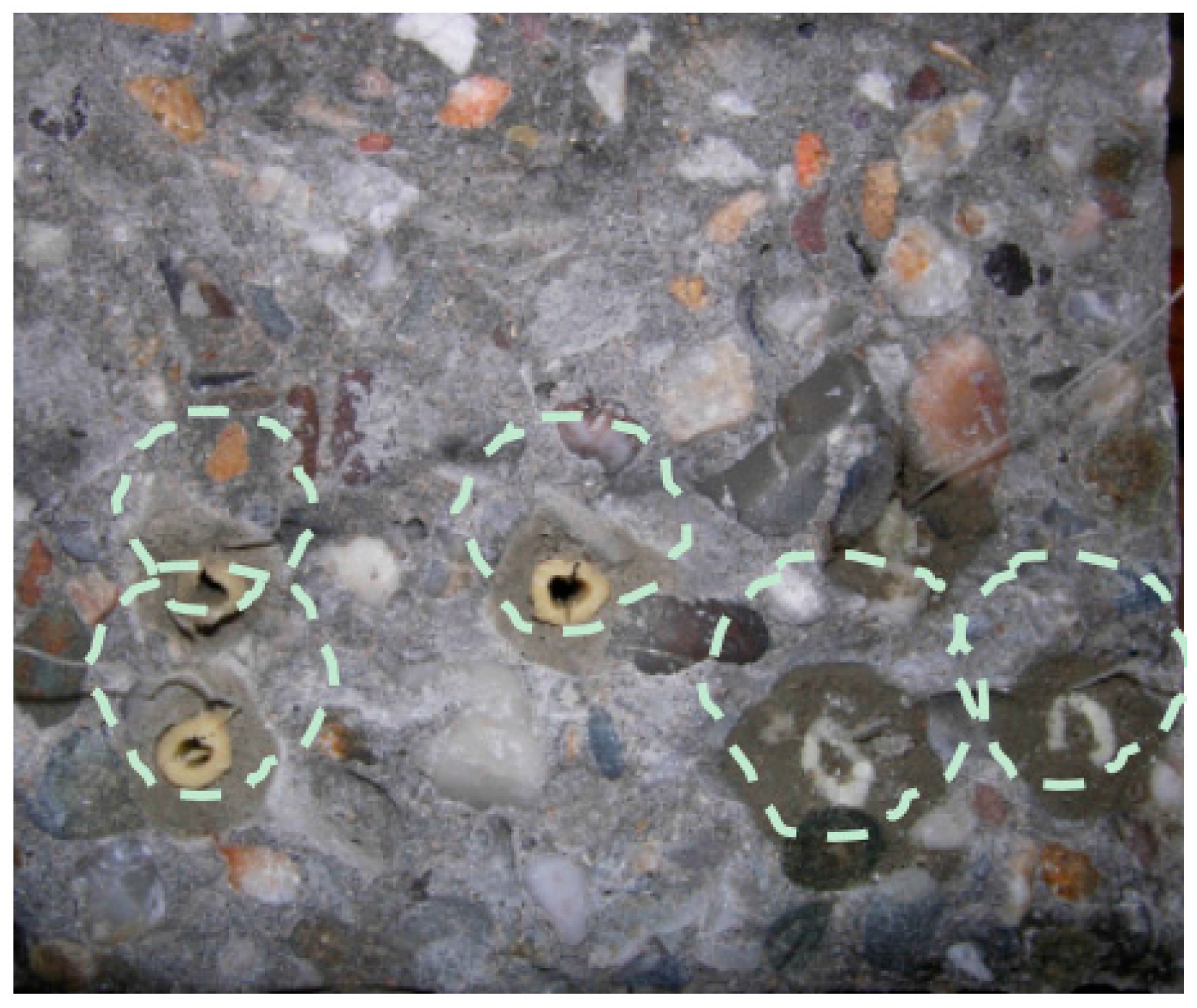
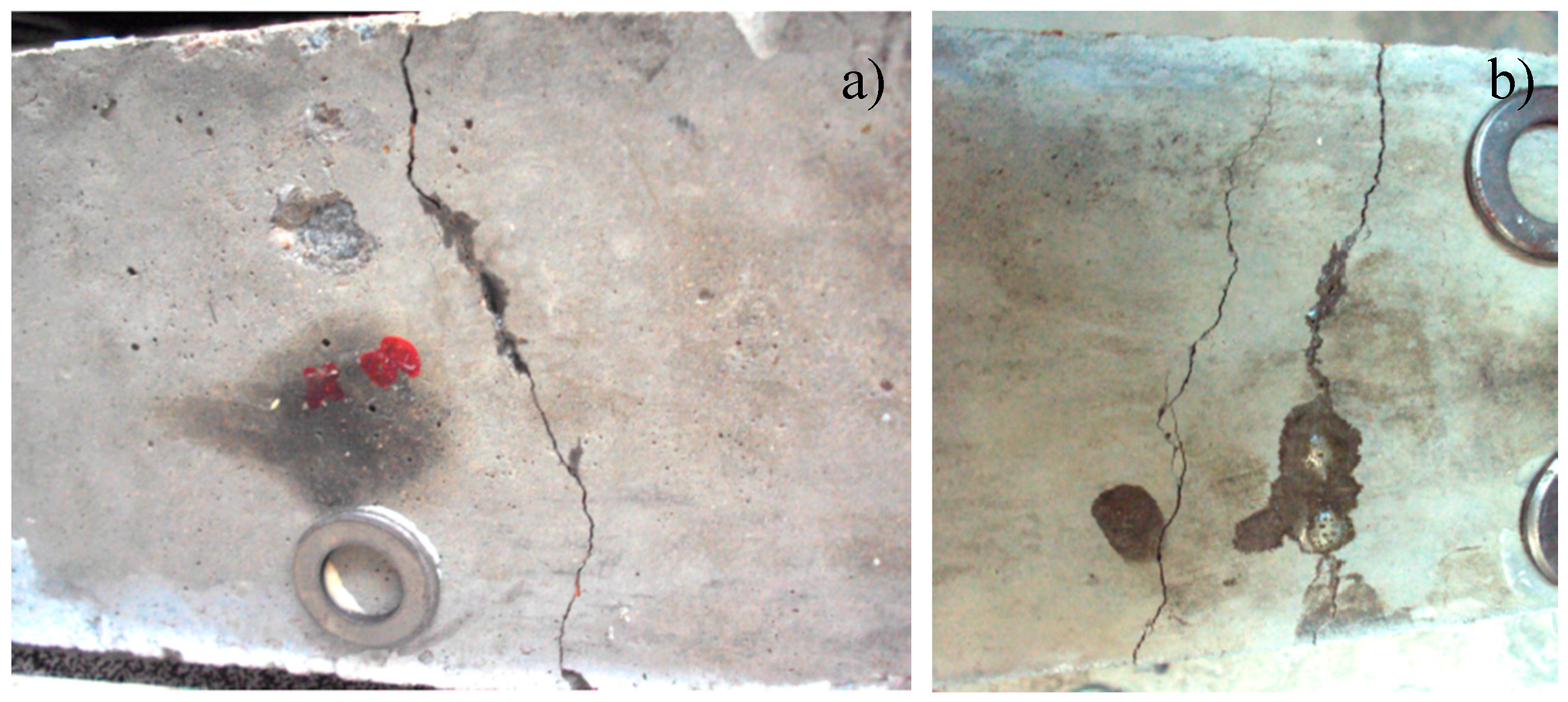
Figure 1.
Concrete fractured surface after bending with the embedded starch-based capsules, the dotted line marks the zone surrounding the capsules.
Figure 1.
Concrete fractured surface after bending with the embedded starch-based capsules, the dotted line marks the zone surrounding the capsules.
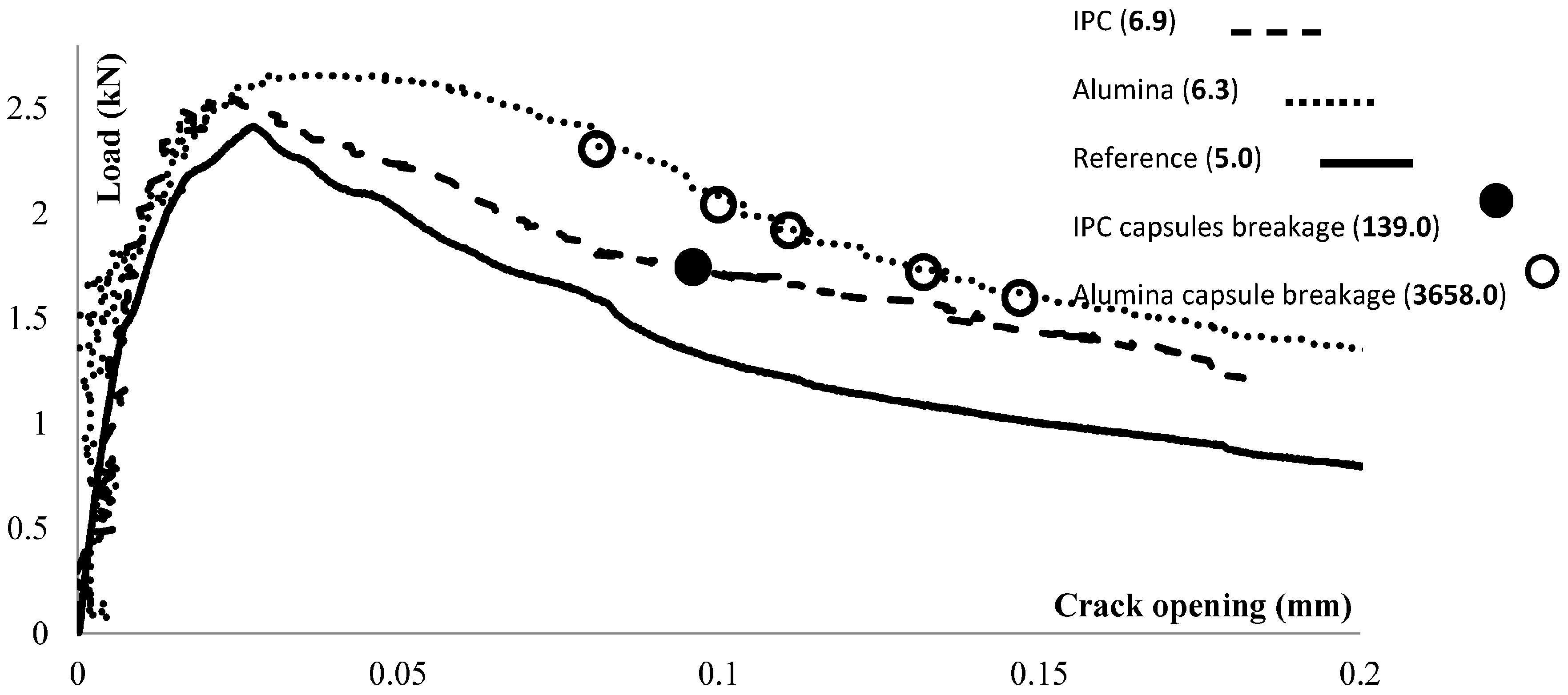
Figure 2.
Reference beam and beams carrying ceramic (alumina) and cementitious (IPC) capsules loaded under three-point-bending.
Figure 2.
Reference beam and beams carrying ceramic (alumina) and cementitious (IPC) capsules loaded under three-point-bending.
Figure 3.
Strain (εxx) and deformation (U) maps of the beam’s side at the end of the each loading cycle: (a,b) cementitious (IPC); and (c,d) ceramic (alumina) tubes.
Figure 3.
Strain (εxx) and deformation (U) maps of the beam’s side at the end of the each loading cycle: (a,b) cementitious (IPC); and (c,d) ceramic (alumina) tubes.
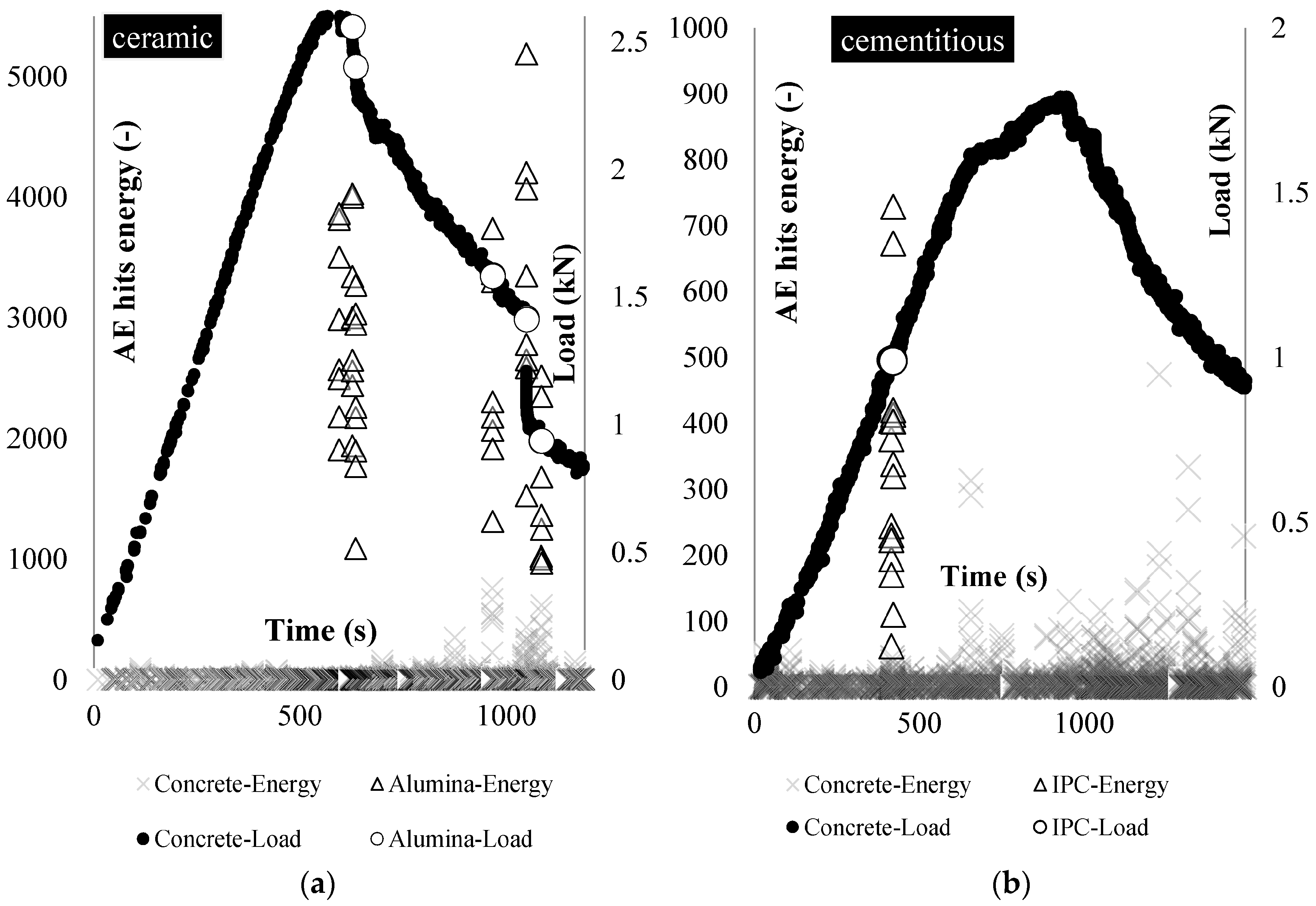
Figure 4.
Beams carrying: (a) ceramic; and (b) cementitious piping network tested under three-point-bending: the load (black points) and the tubes rupture location (red points) based on AE energy analysis (triangular shapes).
Figure 4.
Beams carrying: (a) ceramic; and (b) cementitious piping network tested under three-point-bending: the load (black points) and the tubes rupture location (red points) based on AE energy analysis (triangular shapes).
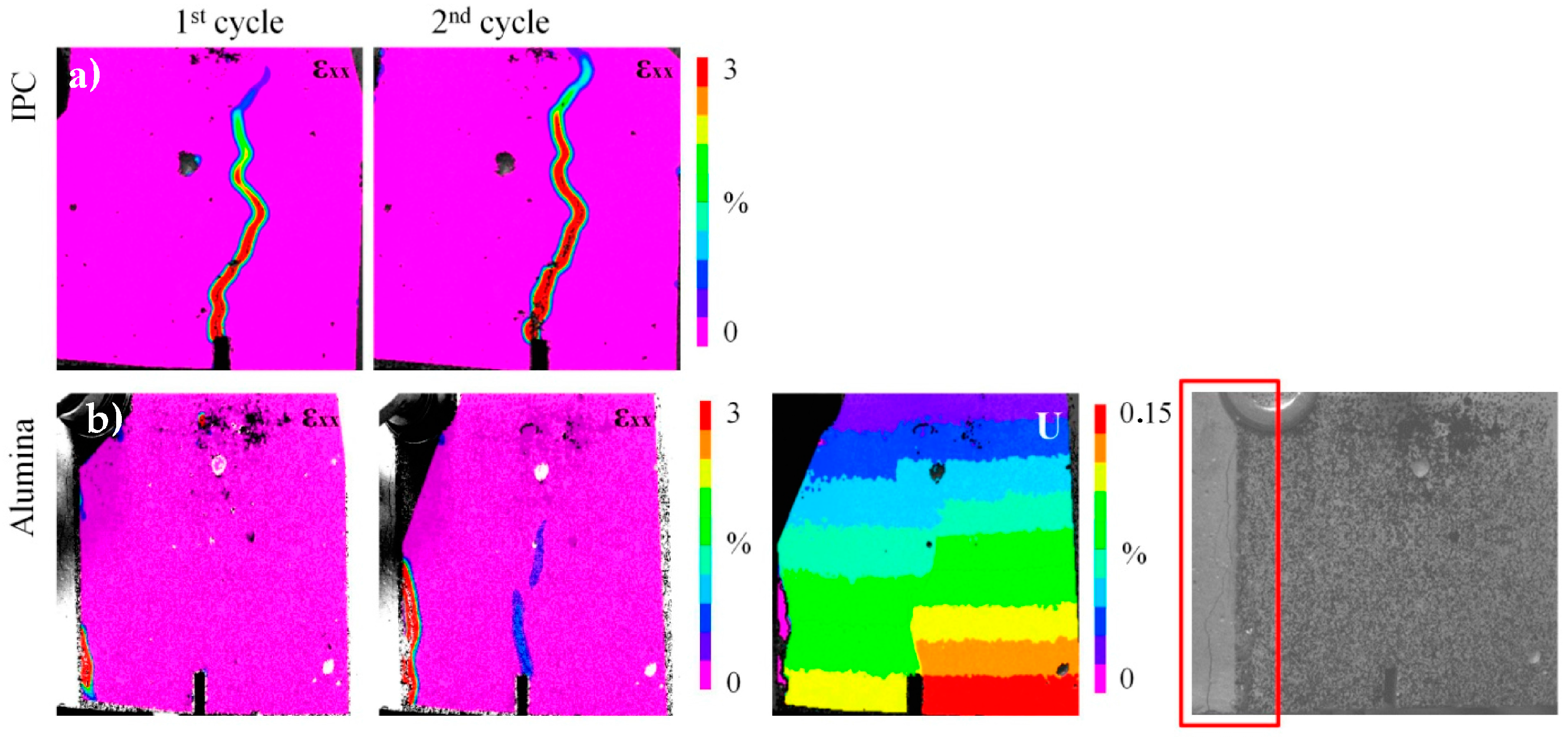
Figure 5.
(a) DIC strain (εxx) maps at the end of loading and reloading cycle (cementitious healing network case); and (b) DIC strain maps (εxx) at the middle region of the beam (ceramic healing network). DIC deformation (U) map at the end of the reloading cycle. The speckle pattern is not wide enough to visualize the crack that forms at the left side of the beam. The crack is shown in the last image of this series, captured at the end of the reloading cycle.
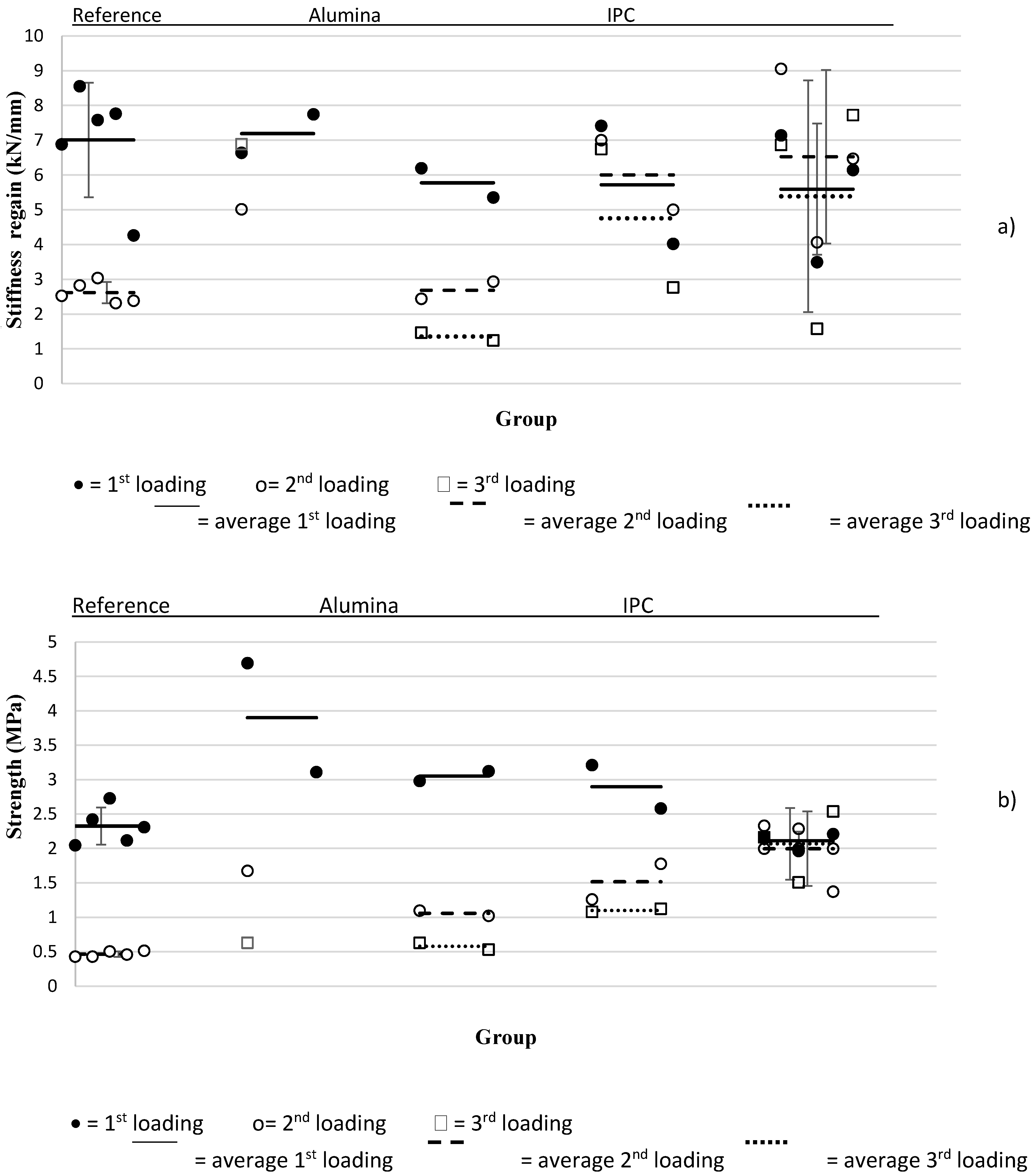
Figure 6.
(a) Strength; and (b) stiffness values overview.
Figure 6.
(a) Strength; and (b) stiffness values overview.
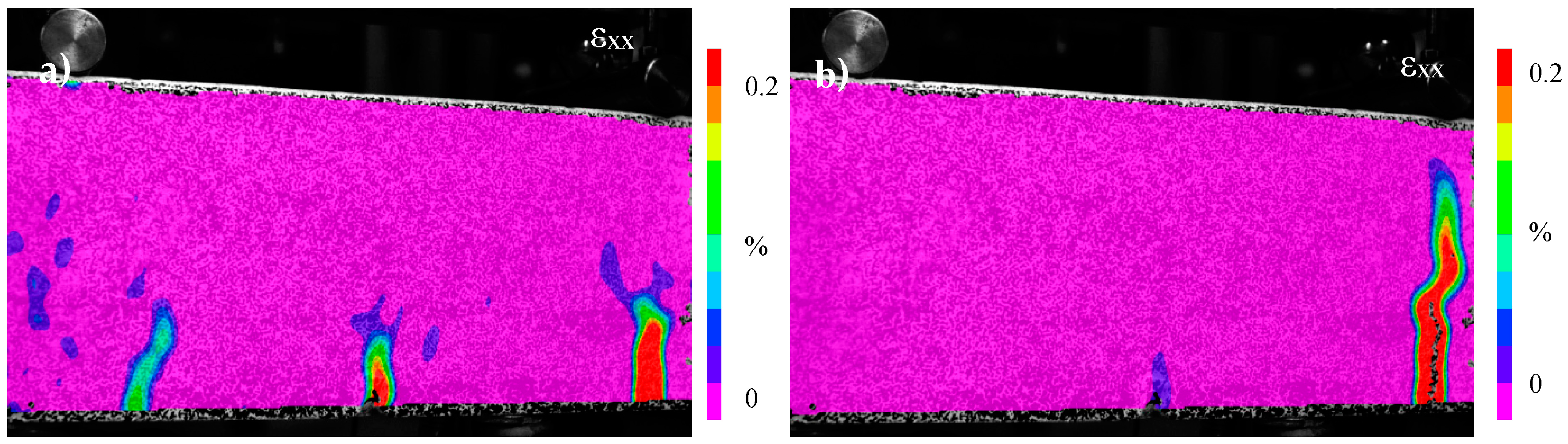
Figure 7.
DIC strain (εxx) profiles—Alumina piping system: (a) multiple cracks form; and (b) macro-crack formed at the 3D printed distribution piece.
Figure 7.
DIC strain (εxx) profiles—Alumina piping system: (a) multiple cracks form; and (b) macro-crack formed at the 3D printed distribution piece.
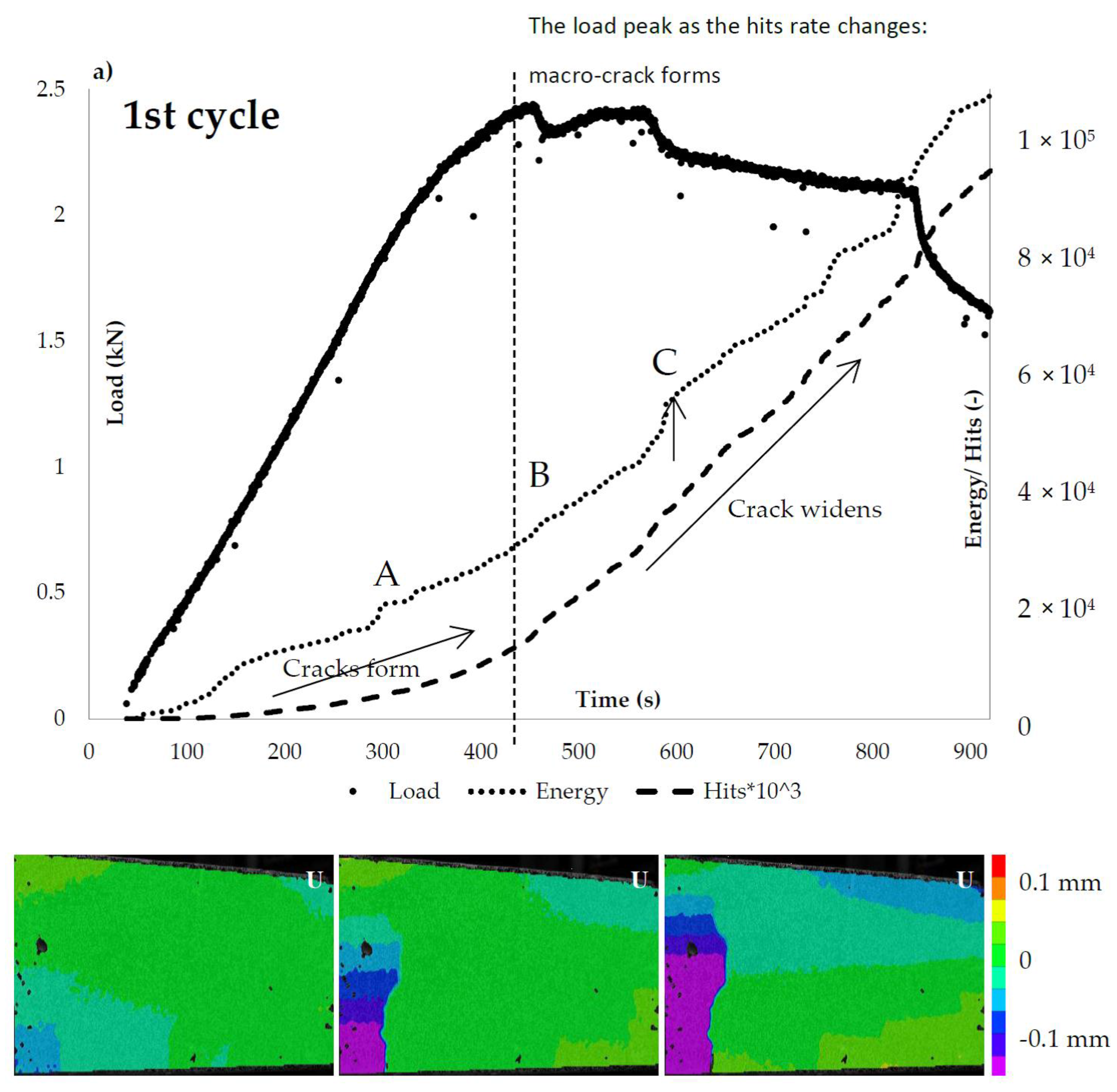
Figure 8.
The ceramic (alumina) vascular system load response and AE hits activity: (a) loading (1st cycle); and (b) reloading (2nd cycle).
Figure 8.
The ceramic (alumina) vascular system load response and AE hits activity: (a) loading (1st cycle); and (b) reloading (2nd cycle).
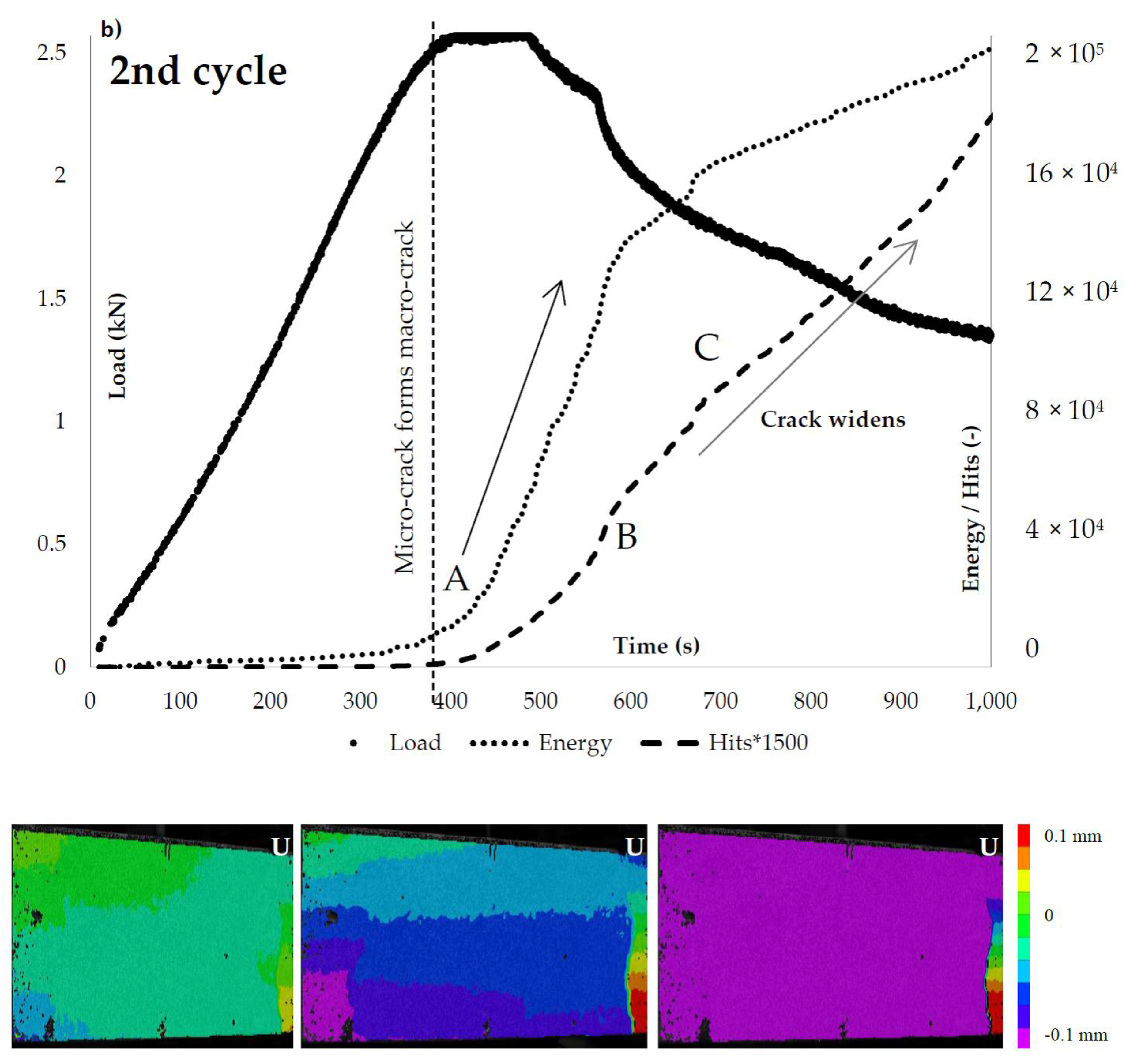
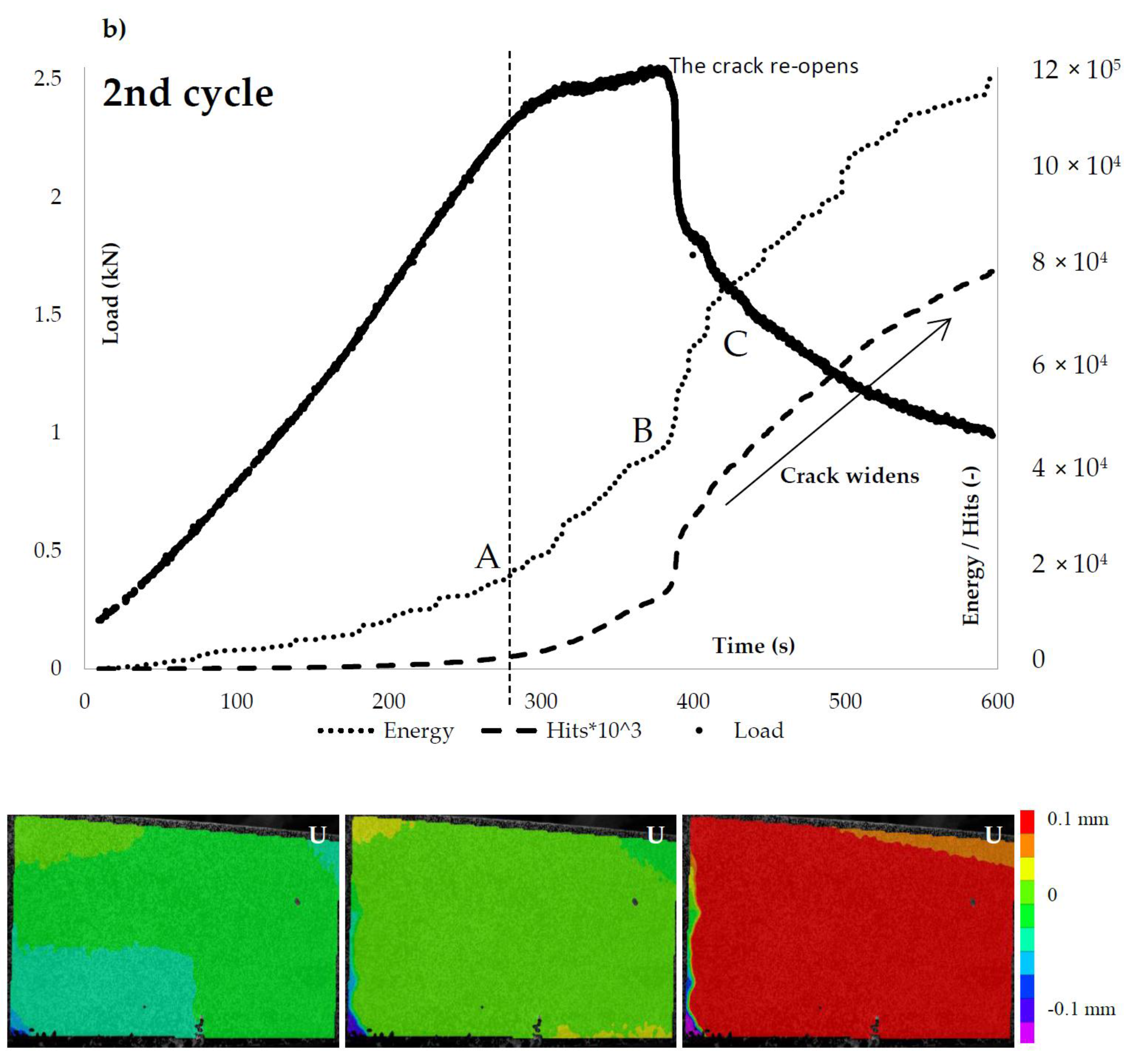
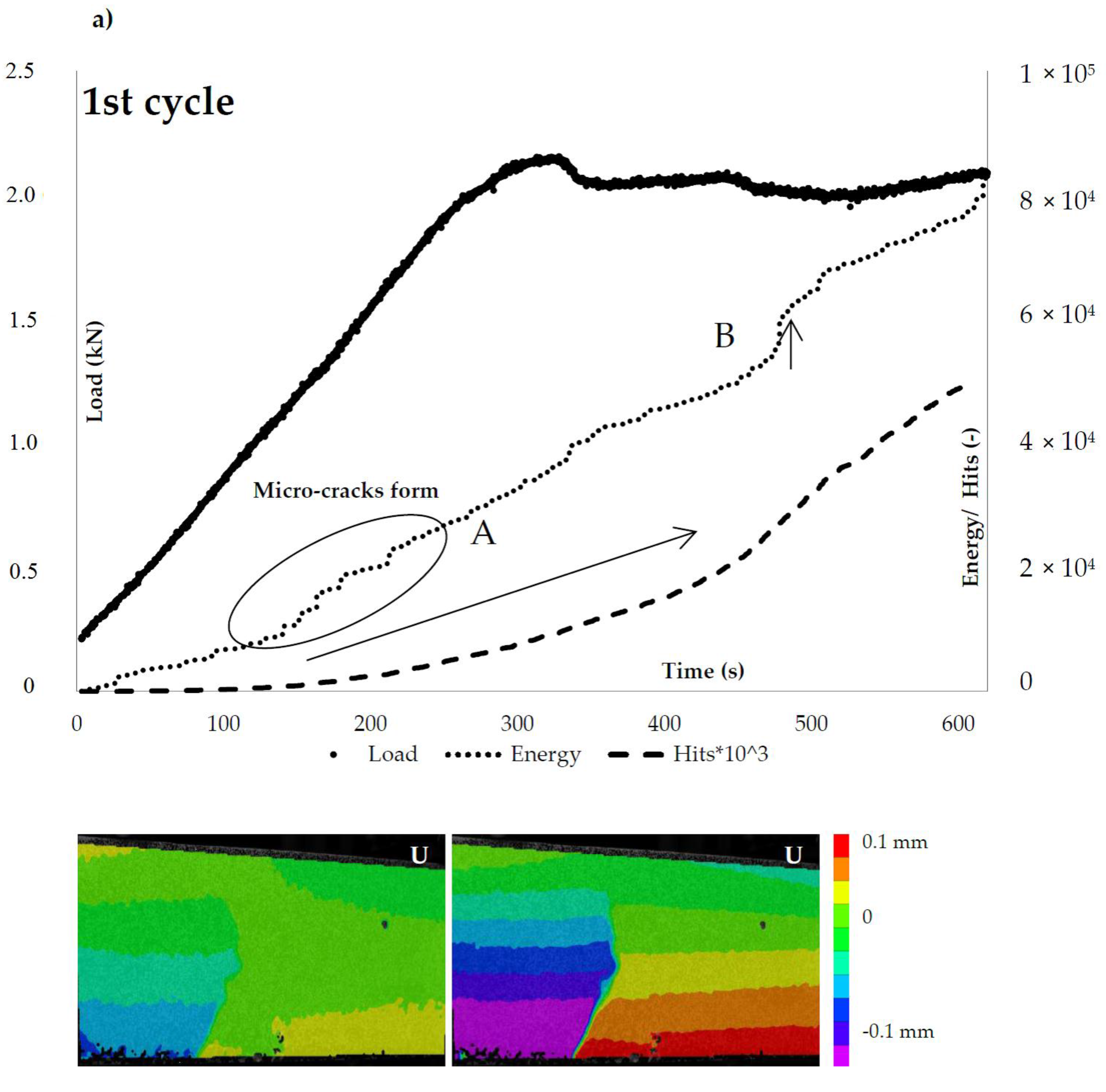
Figure 9.
The cementitious (IPC) vascular system load response and AE hits activity: (a) loading (1st cycle); and (b) reloading (2nd cycle).
Figure 9.
The cementitious (IPC) vascular system load response and AE hits activity: (a) loading (1st cycle); and (b) reloading (2nd cycle).
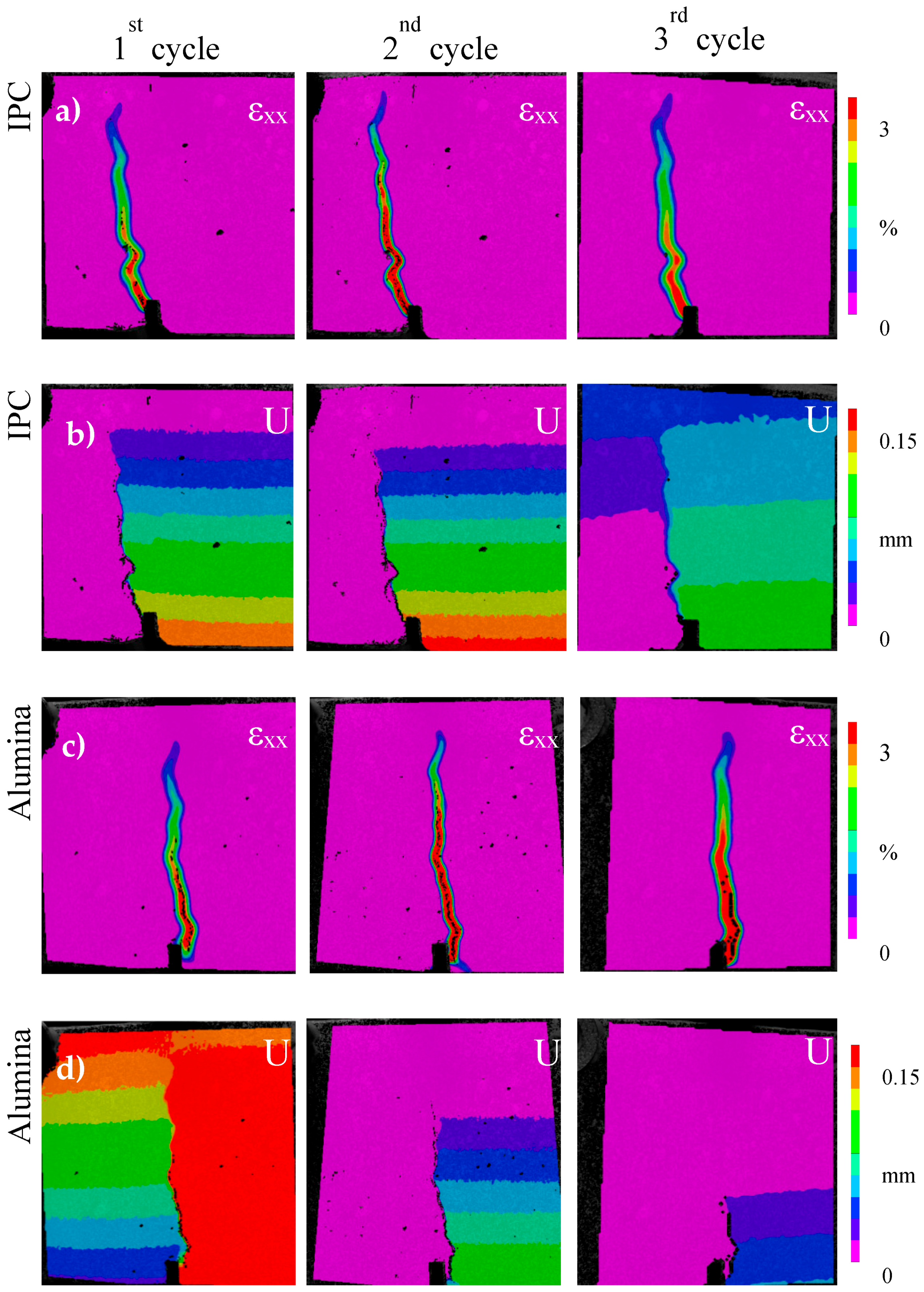
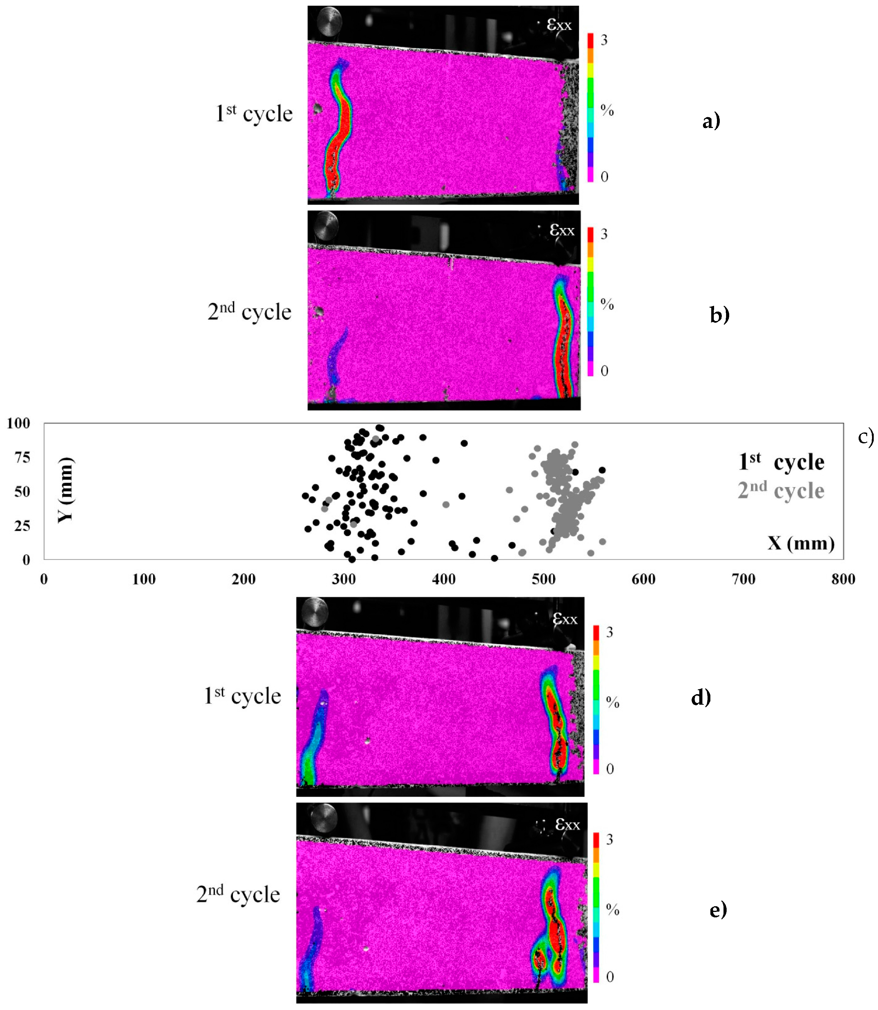
Figure 10.
(a,b) The strain (εxx) maps of beam carrying ceramic (alumina) network healing system at loading and reloading test cycles; (c) the AE events location map (X versus Y coordinates) is given for the first beam; and (d,e) the strain (εxx) maps of a second beam with the same healing system.
Figure 10.
(a,b) The strain (εxx) maps of beam carrying ceramic (alumina) network healing system at loading and reloading test cycles; (c) the AE events location map (X versus Y coordinates) is given for the first beam; and (d,e) the strain (εxx) maps of a second beam with the same healing system.
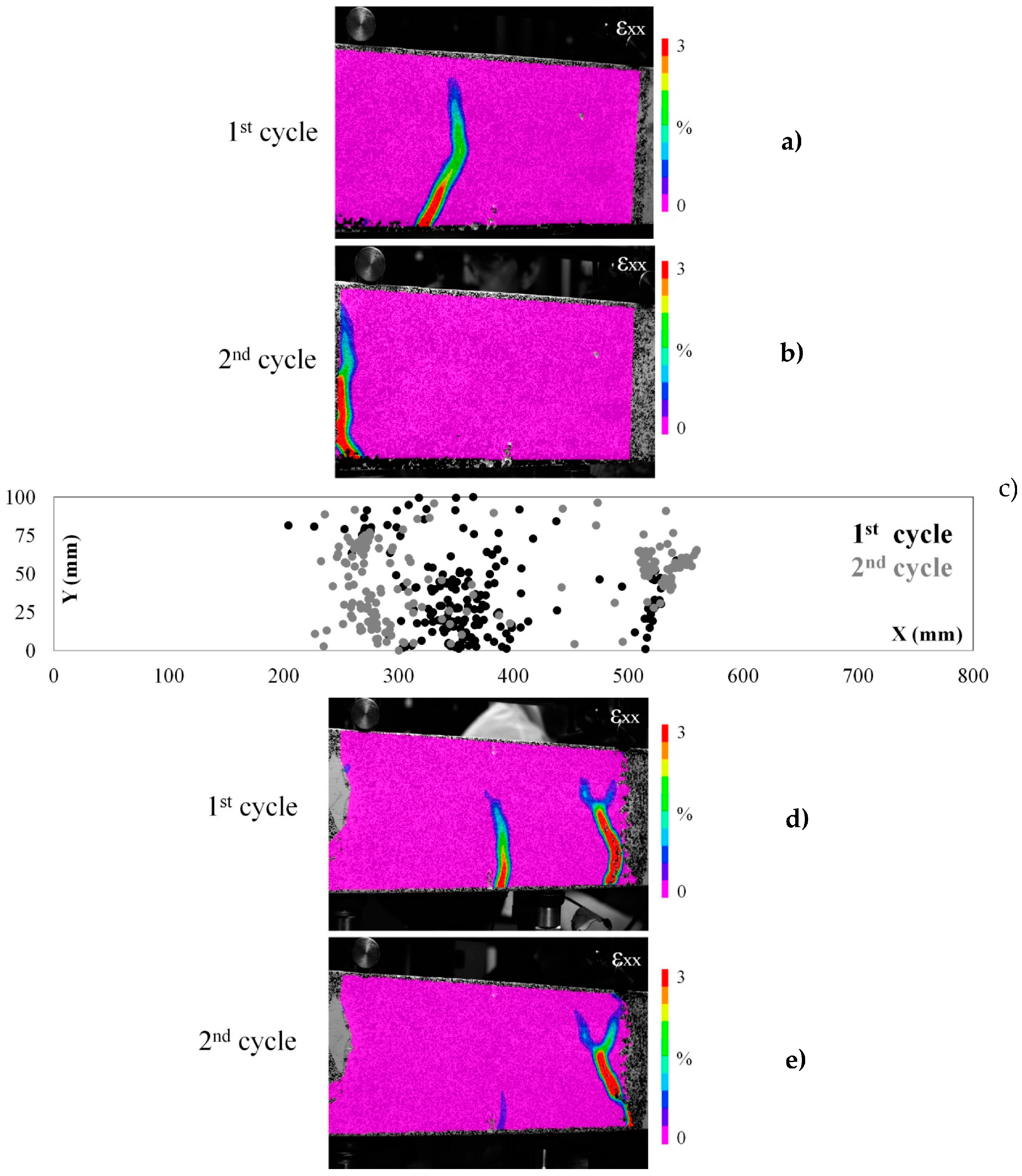
Figure 11.
(a,b) The strain (εxx) maps of beam carrying cementitious (IPC) network healing system at loading and reloading test cycles; (c) the AE events location map (X versus Y coordinates) is given for the first beam; and (d,e) the strain (εxx) maps of a second beam with the same healing system.
Figure 11.
(a,b) The strain (εxx) maps of beam carrying cementitious (IPC) network healing system at loading and reloading test cycles; (c) the AE events location map (X versus Y coordinates) is given for the first beam; and (d,e) the strain (εxx) maps of a second beam with the same healing system.
Figure 12.
The middle of the bottom of the sample with: (a) cementitious; and (b) ceramic piping network. The healing agent leakage is visible.
Figure 12.
The middle of the bottom of the sample with: (a) cementitious; and (b) ceramic piping network. The healing agent leakage is visible.
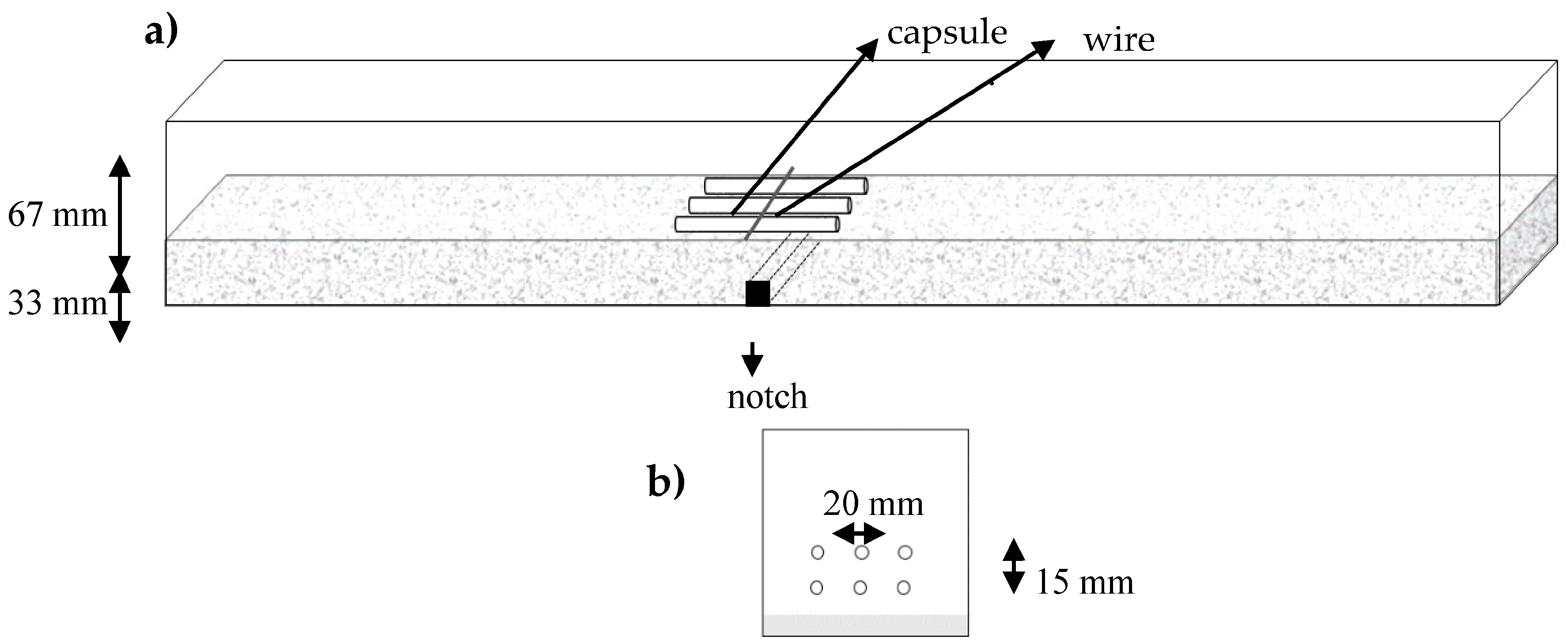
Figure 13.
(a) The process of placing the first layer of three capsules inside concrete beams, the wire keeps the capsules in place; and (b) the cross section with two layers of capsules.
Figure 13.
(a) The process of placing the first layer of three capsules inside concrete beams, the wire keeps the capsules in place; and (b) the cross section with two layers of capsules.
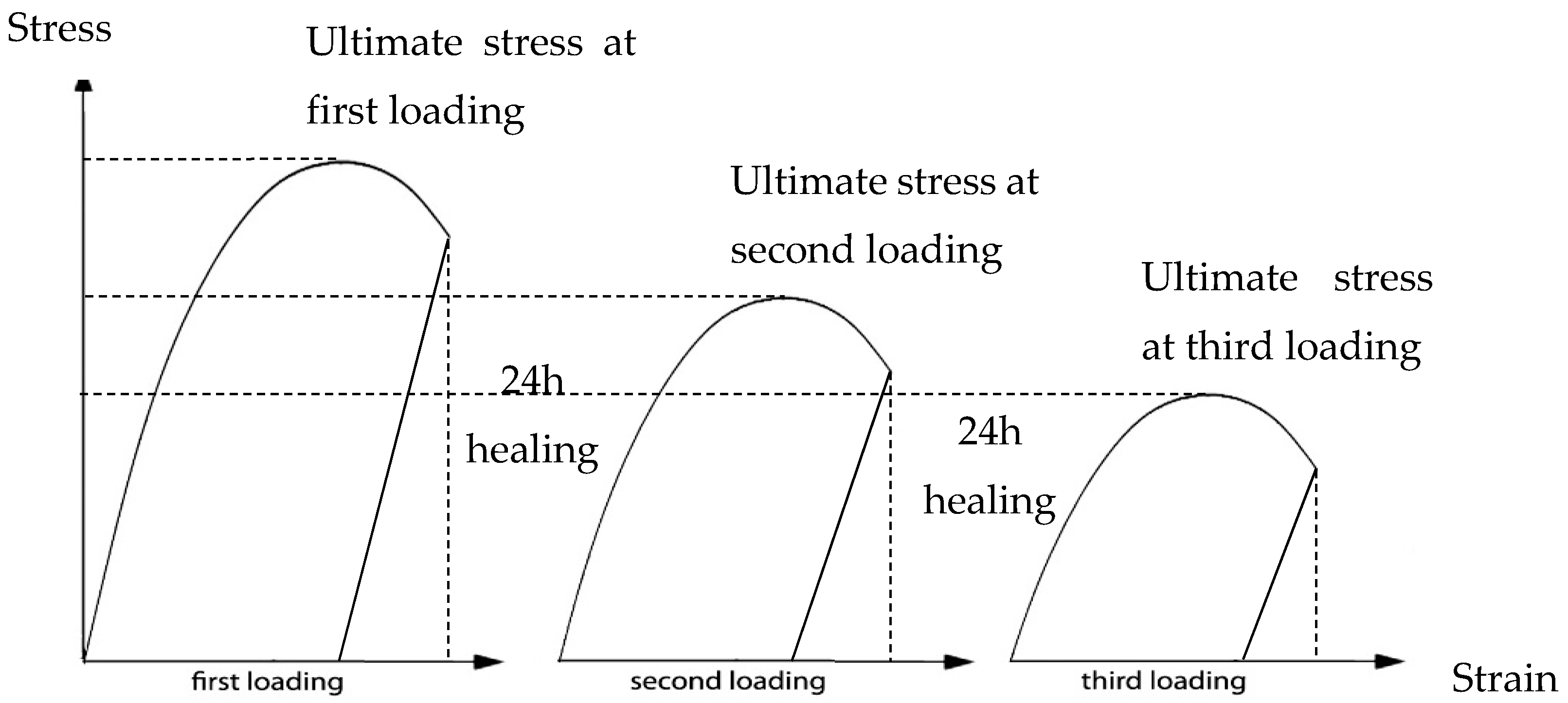
Figure 14.
The mechanical response of the pre-cracked concrete beam under three-point-bending.
Figure 14.
The mechanical response of the pre-cracked concrete beam under three-point-bending.
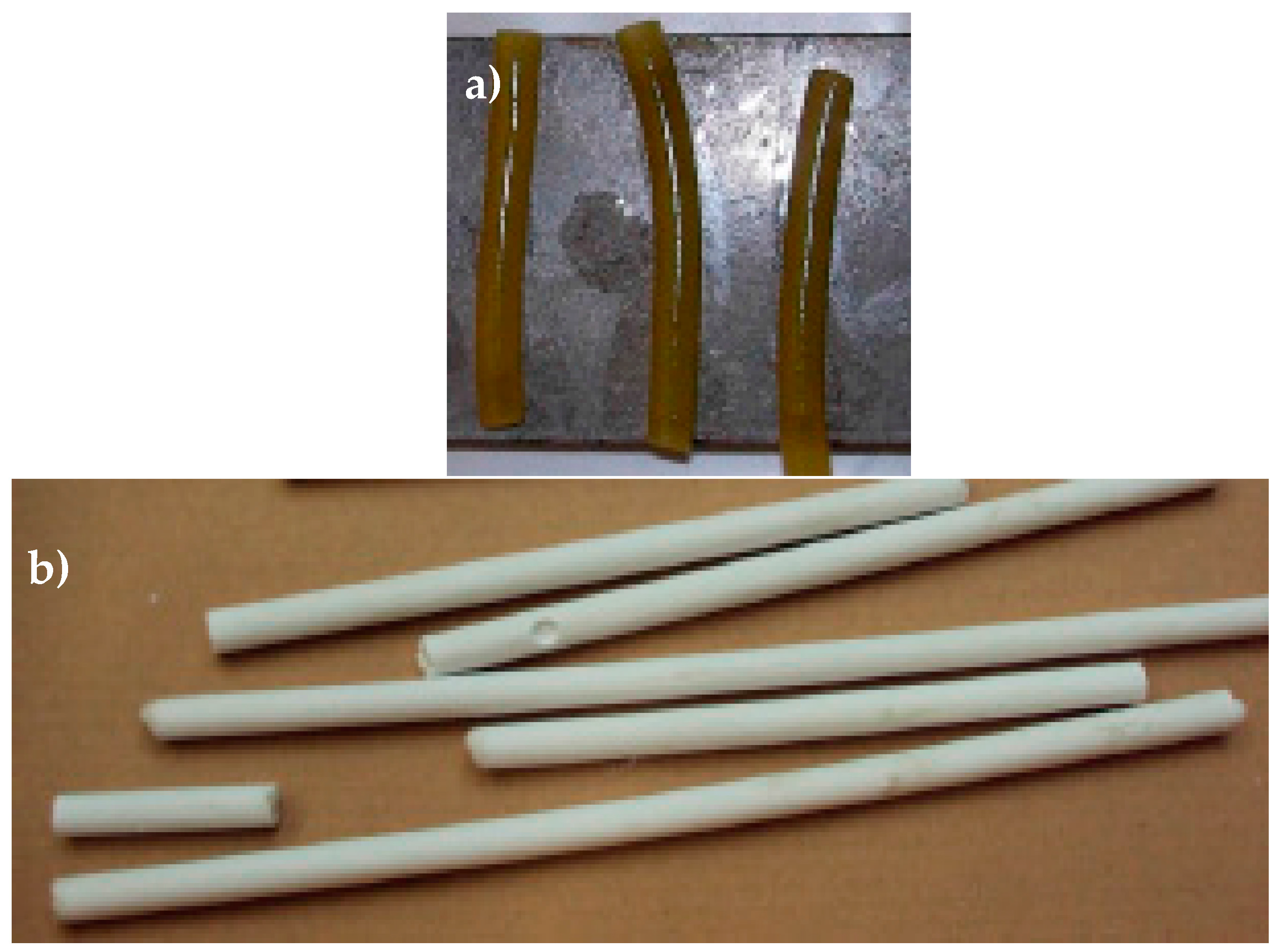
Figure 15.
(a) Starch-based capsules are coated with a water-repellent spray; and (b) IPC tubes after curing.
Figure 15.
(a) Starch-based capsules are coated with a water-repellent spray; and (b) IPC tubes after curing.
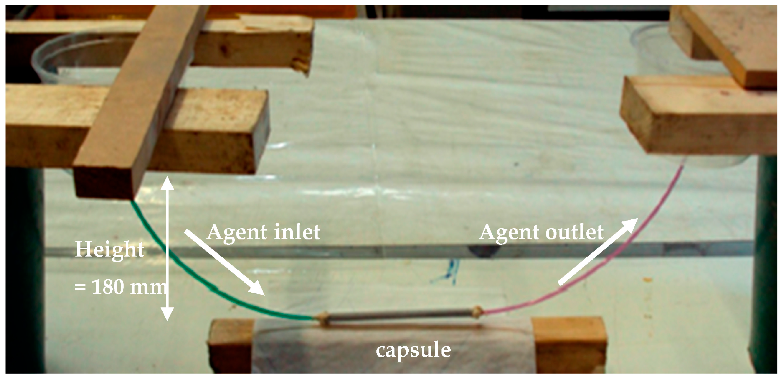
Figure 16.
Testing the flow of PU-based healing agent in one tube.
Figure 16.
Testing the flow of PU-based healing agent in one tube.
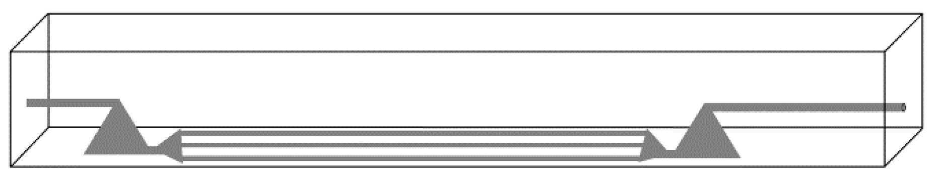
Figure 17.
Vascular concept with tubes, accessible from the outside.
Figure 17.
Vascular concept with tubes, accessible from the outside.
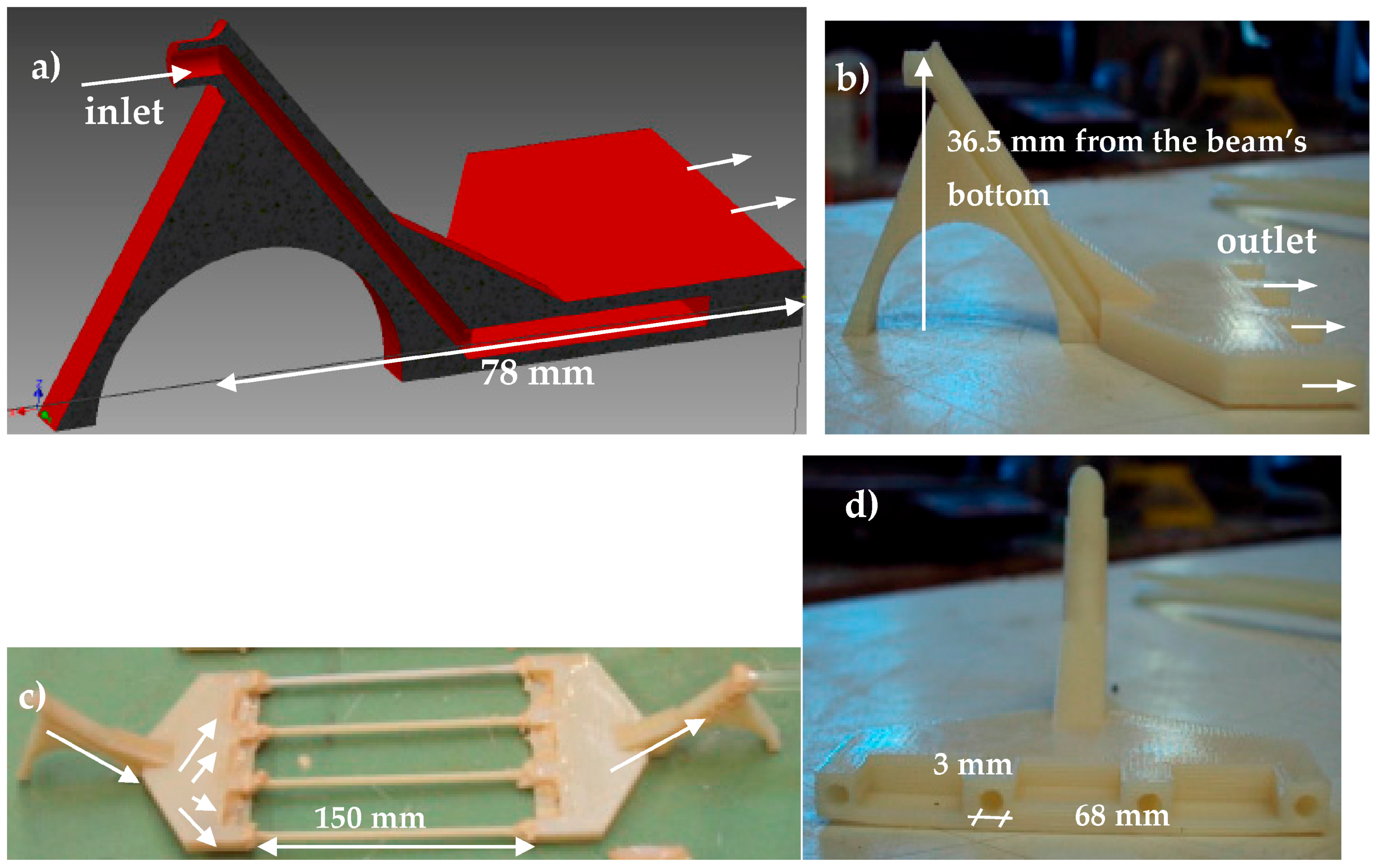
Figure 18.
(a) Cross section of the 3D printed distribution piece (computer model); (b) side view of the printed piece; (c) printed pieces connected to 4 cementitious tubes; and (d) front view of the printed piece.
Figure 18.
(a) Cross section of the 3D printed distribution piece (computer model); (b) side view of the printed piece; (c) printed pieces connected to 4 cementitious tubes; and (d) front view of the printed piece.
Figure 19.
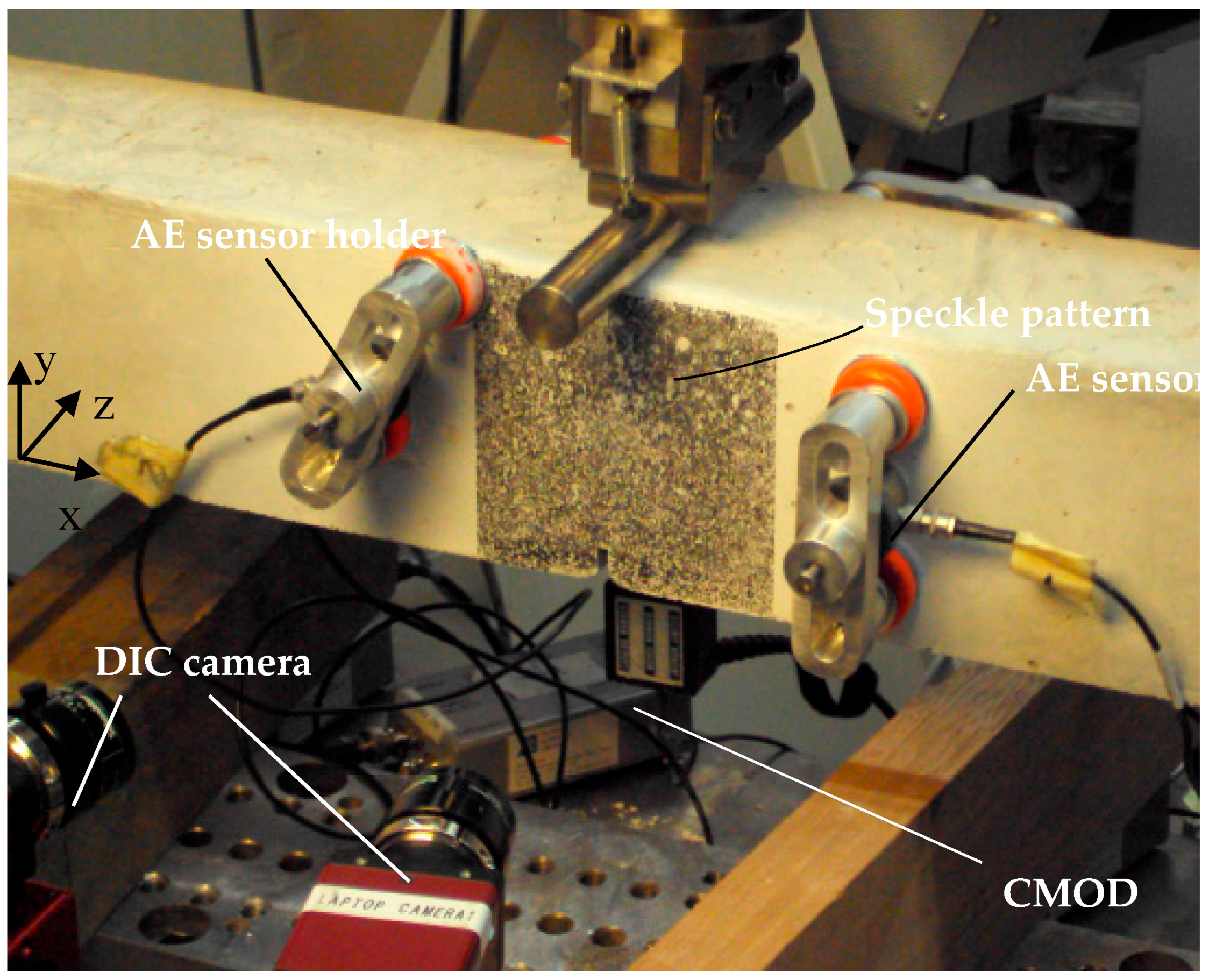
Experimental set-up for three-point-bending with AE-sensors and DIC speckle pattern.
Figure 19.
Experimental set-up for three-point-bending with AE-sensors and DIC speckle pattern.
Table 1.
The mean mechanical recovery of the beams carrying short capsules under three-point-bending.
Table 1.
The mean mechanical recovery of the beams carrying short capsules under three-point-bending.
| Sample Group | 1st Reload | 2nd Reload |
|---|
| ηstrenght (%) | ηstiffness (%) | ηstrenght (%) | ηstiffness (%) |
|---|
| Reference | 15 | 9 | - | - |
| IPC | 34 | 46 | 18 | 23 |
| Alumina | 36 | 76 | 13 | 104 |
Table 2.
Average mechanical recovery for the beams carrying a piping network and loaded under three-point-bending.
Table 2.
Average mechanical recovery for the beams carrying a piping network and loaded under three-point-bending.
| Sample Group | 1st Reload | 2nd Reload |
|---|
| ηstrenght (%) | ηstiffness (%) | ηstrenght (%) | ηstiffness (%) |
|---|
| Reference | 15 | 9 | - | - |
| IPC | 92.3 | 126 | 99 | 96 |
| Alumina | 40 | 94.4 | 34 | 91 |
Table 3.
The mechanical recovery for the beams carrying piping network under four-point-bending.
Table 3.
The mechanical recovery for the beams carrying piping network under four-point-bending.
| Sample Group | 1st Reload | 2nd Reload |
|---|
| ηstrenght (%) | ηstiffness (%) | ηstrenght (%) | ηstiffness (%) |
|---|
| Reference | 15 | 9 | - | - |
| IPC | 83 | 101 | 46 | 108 |
| Alumina | 76 | 102 | 82 | 76 |
Table 4.
Concrete composition.
Table 4.
Concrete composition.
| Component | Weight Fraction (kg/m3) |
|---|
| Sand 0/4 | 670 |
| Gravel 2/8 | 490 |
| Gravel 8/16 | 790 |
| CEM I 52.5N | 300 |
| Water | 150 |
Table 5.
Material properties of PMMA and Borosilicate glass.
Table 5.
Material properties of PMMA and Borosilicate glass.
| Property | PMMA | Borosilicate Glass |
|---|
| Ultimate strength (MPa) | 74 | 6.9 |
| Tensile strain at failure (%) | 0.03 | 0.0001 |
| E-modulus in tension (GPa) | 3.3 | 70 |
| Density (kg/m3) | 1190 | 2230 |
Table 6.
Material properties of IPC and concrete [
25].
Table 6.
Material properties of IPC and concrete [25].
| Property | IPC | Concrete |
|---|
| Compressive strength (MPa) | 80–120 | 28 |
| Tensile strength (MPa) | 6–14 | 2.2 |
| E-modulus in tension (GPa) | 18 | 30 |
| Density (kg/m3) | 2000 | 2400 |
Table 7.
Material properties of alumina (as provided by Ceratec).
Table 7.
Material properties of alumina (as provided by Ceratec).
| Property | Alumina |
|---|
| Bending strength (20 °C) (MPa) | 220–480 |
| E-modulus in tension (GPa) | 390 |
| Density (kg/m3) | 3900 |
Table 8.
An overview of the specimen, their code and the number of carried out loading cycles.
Table 8.
An overview of the specimen, their code and the number of carried out loading cycles.
| Encapsulation System | # of Specimens | # Loading Cycles |
|---|
| Reference | 5 | 2 |
| Tube Alumina | 2 | 2 |
| Tube IPC | 2 | 2 |
| Vascular Alumina | 2 | 3 |
| Vascular IPC | 3 | 3 |


 ,
, 


