1. Introduction
Metals are protected from corrosion in many aqueous environments by the formation of “passive” oxide films that are typically only a few nanometers thick. The transition metal oxides are an important class of functional materials [
1] because of their localized
d electrons [
2,
3,
4]. Among the iron oxides, α-Fe
2O
3, hematite, with an experimental band gap of 2.2 eV [
5] was identified as a charge transfer semiconductor [
2] rather than a Mott–Hubbard insulator because the upper edge of the valence band is dominated by oxygen
p states. Below the Néel temperature (955 K), α-Fe
2O
3 is an antiferromagnetic (AFM) insulator showing weak ferromagnetism above the Morin temperature (260 K), due to a slight canting of the two sublattice magnetizations [
6]. The geometric, electronic, and magnetic properties [
7,
8,
9]; carrier effective masses [
10]; and other related properties on Fe
2O
3 [
11] were present in theoretical work.
The technological importance of these films has led to widespread investigation of their structure, chemistry [
12] and practical applications such as water splitting [
13]. The atomic structure of α-Fe
2O
3 is important to passivity, since this often controls its protective properties, where interfacial strain due to lattice mismatch and charge transfer due to chemical heterogeneity between the Fe oxide film and steel are unavoidable. There could be different factors, such as epitaxial strain, structural deformation, molecular orbital hybridization, and interfacial charge transfer, which affect the properties of the film. However, experimental and theoretical analyses suggest strain and charge transfer are two important extrinsic factors to alter the intrinsic properties of ultrathin Fe oxide films grown on a stainless steel (SS). In fact, strain and interfacial engineering have now become a common strategy to tailor a wide range of thin film properties, from crystalline structure [
14], growth morphology (especially nanoscale assembly) [
15], electronic band structure [
16], magnetism [
17], and carrier mobility [
18] to superconductivity [
19].
It is generally known that SS resistance to stress corrosion cracking is poor, which is largely affected by the structure, thickness, and composition of the passive film [
20]. The strain is an effective approach to modulate the surface work function. Based on experimental observations and theoretical studies, we know that the work function is closely related to the corrosion potential, the lower work function of material, the lower corrosion potential is and the easier corrosion becomes, i.e., the work function is a sensitive parameter to the corrosion behavior [
21]. Strain is expected to affect the fundamental properties of systems, and conversely can be used as an effective mean to tailor the properties of materials for potential applications.
From a theoretical point of view, the main interest in these compounds lies in the role of strong electronic correlations in determining their physical and chemical properties. Motivated by these recent experimental and theoretical studies, we have carried out a systematic study of the electronic properties of α-Fe2O3 film focusing on the effects of strain, based on first-principles calculations. We find that the band gap of the α-Fe2O3 film and work function can be tuned by strain. These calculation results allow us to conclude that the electronic structure and work function of α-Fe2O3 film could be modified by strain when the α-Fe2O3 film is grown on a SS, which can be very useful for explaining the effect of strain, future experimental studies as well as fundamentally understand the corrosion behavior.
2. Methods
First, as is typical for transition-metal compounds, both GGA and the LDA+U corrections reduce the LDA overbinding problem and increase the equilibrium volume which becomes close to the experimental value. Rohrbach et al. [
22] performed a GGA+U calculation for Cr
2O
3 and obtained more reasonable results for the band structure. However, this approach is inaccurate for structural and magnetic properties. Mosey et al. [
23] obtained better overall agreement with experiment for structural and spectral properties using the spherically averaged LSDA+U method with U − J = 3.2 eV. For α-Fe
2O
3, because Fe d bands are strongly correlated, researchers adopted the LSDA+U approach [
24,
25]. Therefore, we tend to use LDA+U method for α-Fe
2O
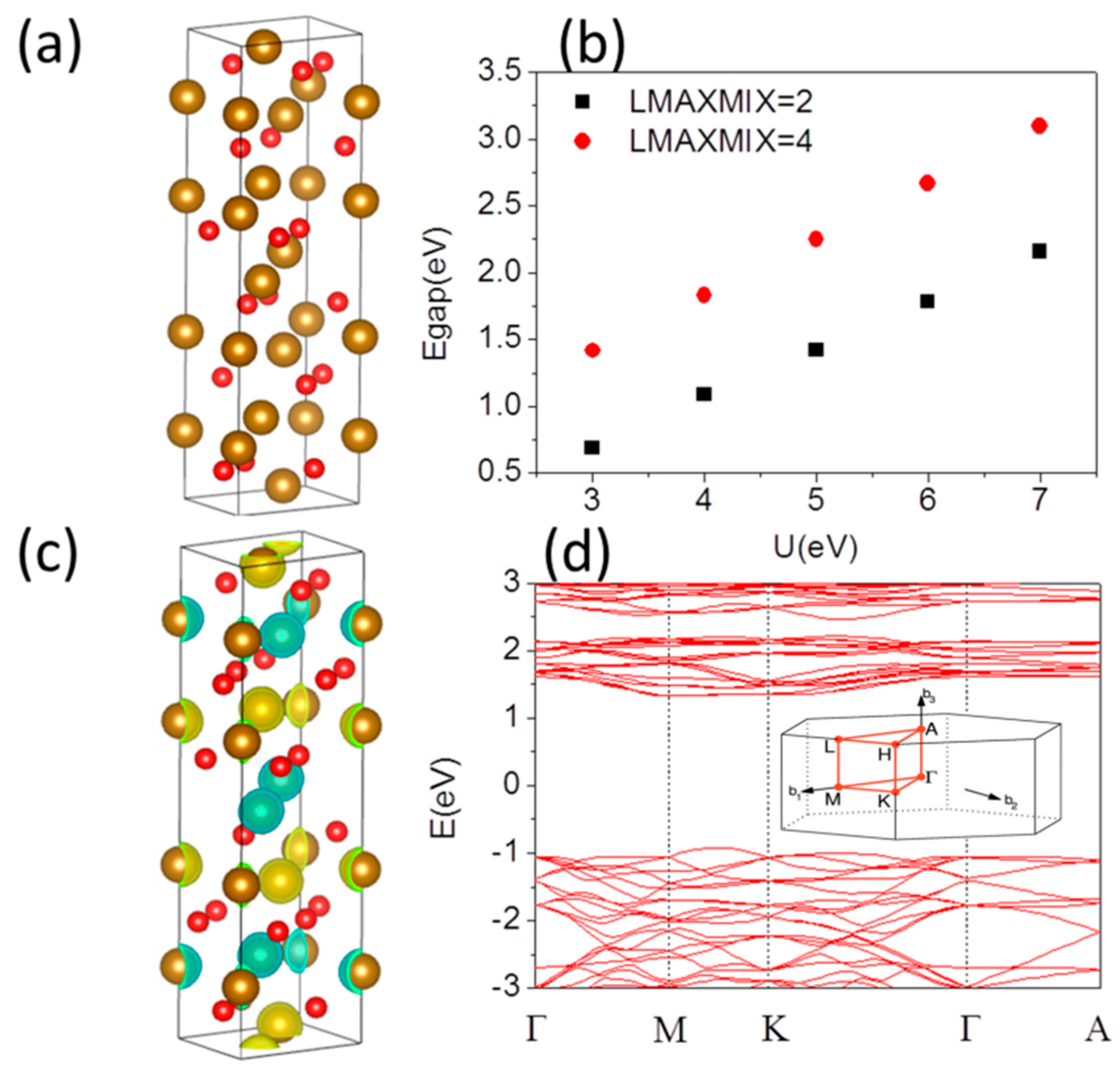
3 system. The hexagonal lattice of α-Fe
2O
3 film is shown in
Figure 1a. The electronic band structures and electronic properties were calculated as before [
26,
27,
28,
29,
30] in the framework of the (Slater exchange [
31] plus Vosko–Wilk–Nusair correlation [
32]) local density approximation LDA+U using Vienna Ab initio Simulation Package (VASP) package. The energy cutoff of 400 eV was selected to converge the total energy within 1 meV/atom on 5 × 5 × 5 and 5 × 5 × 1 (or 9 × 9 × 1) Monkhorst–Pack k-point mesh for bulk and film, respectively. For the calculation of band structures within the L(S)DA+U approach, it is hence strictly required to increase LMAXMIX (a parameter in VASP code) to 4 (
d elements). For structural relaxation, all the atoms are allowed to relax until atomic forces are smaller than 0.01 eV/Å. The optimized lattice constant for bulk is
a = 4.916 Å which is close to experimentally derived structural parameter 5.035 Å [
33]. It is expected that different surface Fe and O terminations will also lead to significant differences in the electronic and work function of the systems. We defined the strain percent as (
a −
a0)/
a0, where
a0 is the experimental lattice constant without strain, and
a is the lattice constant under compressive or tensile strain. The polar (0001) surface has been modeled by symmetric slabs containing 1–3 hexagonal unit cell layers for the Fe and O terminated surfaces and a 1 × 1 periodicity in the surface, containing 30 (33) to 90 (93) atoms, respectively. The use of symmetric slabs cancels out dipole moments, which can occur in nonsymmetric slabs. The vacuum layer is 15 Å thick for α-Fe
2O
3 films with strains up to ±6% (+ for tensile strain, − for compressive strain). The band gaps are calculated for different U parameters. The Coulomb repulsion is characterized by a spherically averaged Hubbard parameter U and a parameter J representing the screened exchange energy. While U depends on the spatial extension of the wave functions and on screening, J is an approximation of the Stoner exchange parameter and almost constant J ~1 eV. In our calculation the J is set to be 0.5 eV.
Figure 1b shows the band gap of α-Fe
2O
3 bulk as a function of U parameter of Coulomb repulsion. The band gap increases with increasing U parameter. It is important to be aware of the fact that when using the LDA+U, in general, the total energy will depend on the parameters U and J. Thus, it is not meaningful to compare the total energies resulting from calculations with different U and/or J (U − J in the case of Dudarev’s approach [
24]). The energy depends on the difference (U − J) introduced by Dudarev.
In Dudarev’s approach, the parameters U and J are not entered separately, only the difference (U − J) is meaningful. The more the U
eff (U − J) is, the more the band gap is. A larger (U − J) lowers the one-electron potential locally for a particular Fe d orbital and in turn reducing the hybridization with O atoms and enlarging the band gap. The band gap 2.22 eV with U = 5 eV is in agreement with experimentally derived 2.2 eV [
5]. If the computational lattice constants are used for the spin state calculations, there is a band gap difference slightly compared with experimental one with same U and J. U = 5 eV provides a good description of the band gap and magnetic moment of Fe, while higher values of U give a larger band gap than the experimental one. Thus, in our following calculations, we use U = 5 eV.
3. Results and Discussion
The α-Fe
2O
3 is an AFM insulator [
6] because of the strong superexchange interaction mediated by the O atoms. Different magnetic ordering including the A-type AFM (+ + − −) and G-type AFM (+ − + −) [
34] states have been studied using the experimental observed lattice constants. A-type AFM ordering + + − − state is energy favored, which means that Fe atoms in short distance along the hexagonal axis, have opposite magnetic moment, while Fe atoms in larger distance have equal magnetic moments. The spin-density distributions of this system presented in
Figure 1c, where the up- and down-spin densities are denoted by light yellow and green color, respectively, clearly indicating the AFM (ferromagnetic) coupling along the c-direction (ab-planes). The magnetic moments are well localized on the Fe ions. It is calculated to be 4.25 μ
B compared to an experimental value of 4.64 μ
B [
35]. The corresponding band structure is shown in
Figure 1d. Although there is some admixture of O-
p states throughout both the filled and unfilled bands, the about 90% contribution to valence band comes from oxygen
p states, while the occupied 3
d levels of Fe lie around 6–7 eV below the Fermi level and at 0–3 eV below the Fermi level dominated by O 2
p states is more pronounced. This is a consequence of the fact that the on-site Coulomb potential acts only on the Fe 3
d states, leading to a reduction of the Fe–O hybridization which is too strong. The conduction band minimum (CBM) is mainly populated by the unoccupied 3
d levels of Fe. In α-Fe
2O
3, the oxidation states of O and Fe are −2 and +3, respectively. Therefore, maghemite is a charge-transfer type of insulator rather than a Mott–Hubbard insulator, and the first excitation term should correspond to the transfer of electrons from the O
2− anions to the octahedral Fe
3+ cations. The band structure of α-Fe
2O
3 has an almost dispersionless CBM between the M and K points in the first Brillouin zone seen from
Figure 1d. This indicates that pure α-Fe
2O
3 has extremely heavy carrier effective masses, which will result in low mobility for the electrons. The conduction band between Γ and A is also very flat and at higher energy compared to the CBM. It implies that interlayer conduction along the
z-direction will be severely suppressed; the conductivity is known to be highly anisotropic, being significantly higher within the layers in the ab-plane. On the other hand, the favorable
p-
d hybridization between the O
p and Fe
d states leads to dispersion feature between M and K points of valence band maximum (VBM). Therefore, holes have a lower effective mass, which would suggest a higher mobility compared to electrons.
It was confirmed that the oxide film on steel after exposure to H
2O
2 and O
2 environments consists mainly of hematite (α-Fe
2O
3) [
36], although there would be Fe
3O
4, Fe(OH)
3 and so on. Depending on the aqueous environment, the thickness of α-Fe
2O
3 thin films varies from a few to several 100 nm. There are three possible planes to terminate the bulk to form a clean (0001) surface: a single Fe layer, a double Fe-Fe layer, or an oxygen layer, as indicated in the following notation: Fe-O3-Fe-R, Fe-Fe-O3-R, and O3-Fe-Fe-R, where R represents the continuing bulk atomic stacking sequence. Under ultrahigh vacuum conditions, the experimental and theoretical evidence was consistent with a highly relaxed Fe-terminated surface, Fe-O3-Fe-R, for α-Fe
2O
3 [
37,
38]. This is the most stable surface from a stoichiometric and electrostatic perspective, as the polar oxygen anion layer is stabilized by an equal number of positive metal cations above and below [
39]. For a comparative study, we have focused on two different Fe terminated (Fe-O3-Fe-R) and O terminated (O3-Fe-Fe-R) α-Fe
2O
3 thin film, respectively. The optimized lattice constant for 1 × 1 × 1 Fe terminated α-Fe
2O
3 thin film is
a = 5.014 Å which is in agreement with experimentally derived structural parameter 5.035 Å [
33]. In our study we use
a = 5.035 Å.
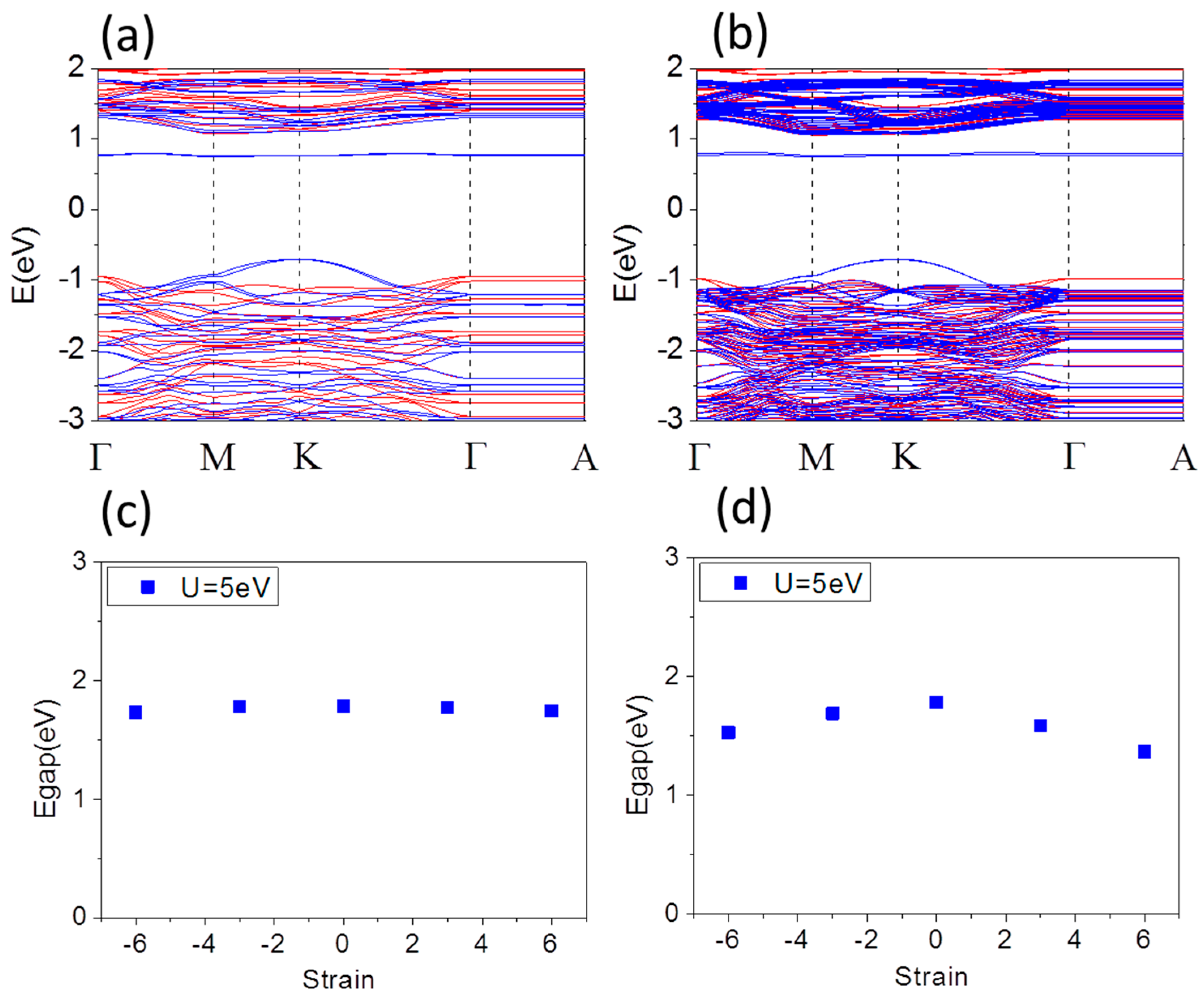
Figure 2a,b shows typical band structures of free standing Fe terminated α-Fe
2O
3 1 × 1 × 1 and 1 × 1 × 3 thin film with thickness 1.31 nm corresponding cell with 30 atoms and 4.06 nm corresponding supercell with 90 atoms, respectively. There is almost no change in the features of the CBM because it still has Fe 3
d character. On the Fe-terminated surface with a reduced Fe content in the top layer, the coordination of the surface Fe atom is very different from the octahedral environment in the bulk. The favorable
p-
d hybridization between the O
p and Fe
d states extends to dispersion region from M-K line to M-K-Γ of valence band maximum (VBM). The band gap is 1.78 and 1.79 eV in
Figure 2a,b for Fe terminated α-Fe
2O
3 1 × 1 × 1 and 1 × 1 × 3 thin film, respectively, which is smaller than that of bulk. The electronic band at the surface differs from that in the bulk mostly by a pronounced narrowing of the Fe-derived bands resulting from the reduced coordination of the Fe atoms. That does not follow the traditional rule of “the band gap of bulk is smaller than that of film” [
40]. The Fe-surface moment is 3.99 (4.00) μ
B in 1 × 1 × 1 (1 ×1 × 3) thin film. Hence, for the Fe-terminated surface, the magnetism of the surface should not differ appreciably from that in the bulk. Moreover, the in-plane lattice constant of α-Fe
2O
3 thin films does not match the steel substrate exactly with a perfect coherent interface, so that compressive (− %) or tensile (+ %) strain is suggested to play an important role in affecting the electronic structure of α-Fe
2O
3 films.
Figure 2c,d shows the band gap of 1 × 1 × 1 and 1 × 1 × 3 supercell of Fe terminated α-Fe
2O
3 thin film as a function of biaxial strain from compressive −6% up to tensile 6%, respectively. The band gaps of 1 × 1 × 3 supercell are significantly reduced, while the combination of the quantum confinement and surface coupling effect is likely to leads to the band gap of 1 × 1 × 1 cell decreasing slightly. Under compressive strain up to −6% the Fe-surface magnetic moment of 1 × 1 × 1 (1 × 1 × 3), supercell decreases from 3.99 (4.00) μ
B to 3.90 (3.80) μ
B, while it increases slightly from 3.99 (4.00) μ
B to 4.04 (4.04) μ
B under tensile strain up to 6%.
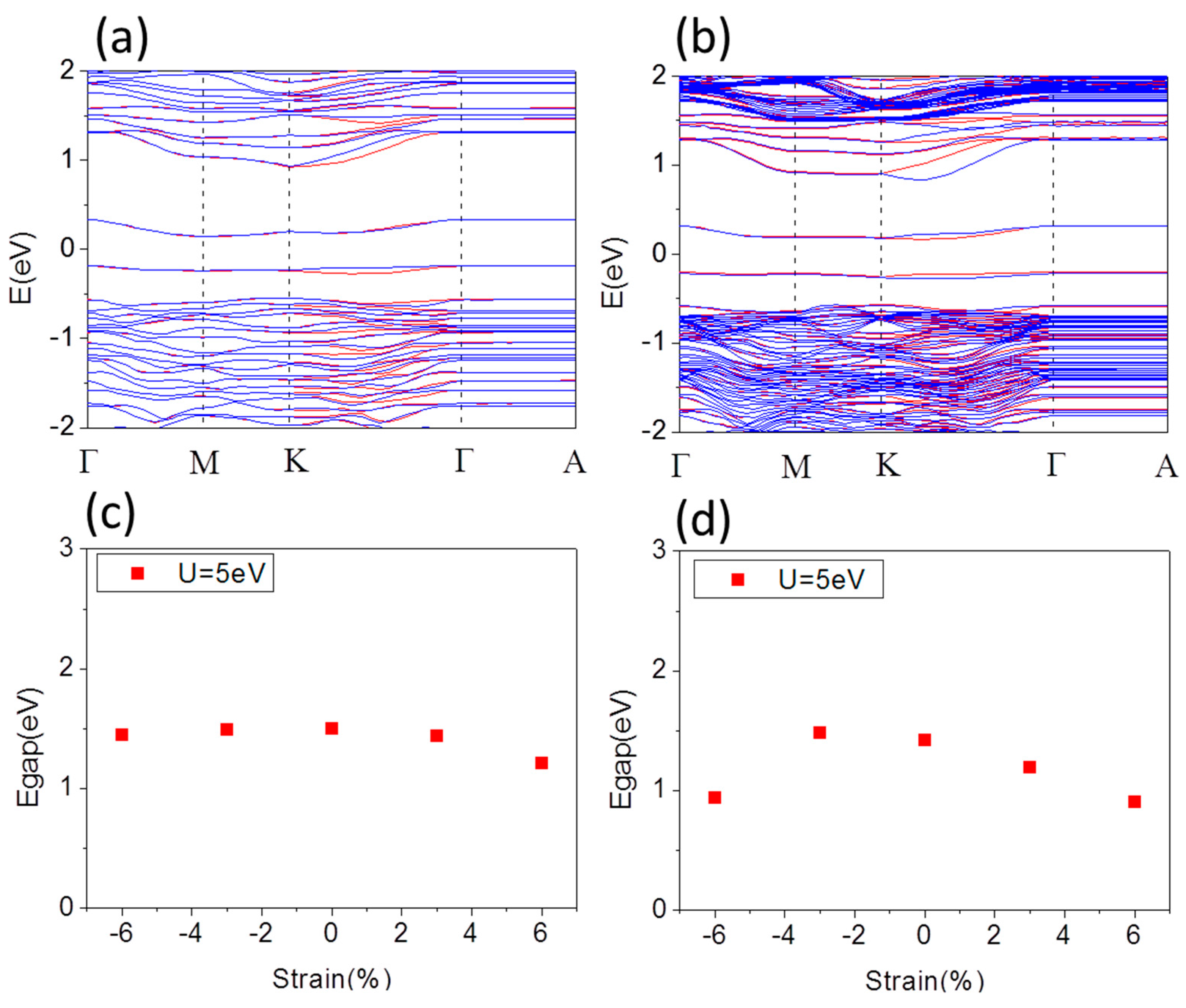
Figure 3a,b shows the typical band structure of free standing O terminated α-Fe
2O
3 1 × 1 × 1 thin film with thickness of 1.37 nm corresponding cell with 33 atoms and 1 × 1 × 3 thin film with thickness of 4.12 nm corresponding supercell with 93 atoms, respectively. The band gap is 1.50 eV and 1.48 eV, respectively, which is smaller than that of bulk, even smaller than that of Fe terminated α-Fe
2O
3 thin film. In O terminated α-Fe
2O
3 thin film there is more electrons transfer from Fe to O, so that
d Coulomb repulsion decreasing results in band gap decreasing much. The spin splitting only induces along K-Γ line. Two even bands showing spin split slightly along K-Γ line of band structure, are just below and above E
F, which mainly comes from the
p orbitals of O-surface atoms. In this case, the CBM becomes more dispersive than that of the pristine α-Fe
2O
3, indicating that O terminated α-Fe
2O
3 thin film may reduce the effective mass for electrons. Similarly, we investigate the electronic structure modulation of O terminated α-Fe
2O
3 films by strain.
Figure 3c,d shows the band gap of 1 × 1 × 1 and 1 × 1 × 3 supercell of O terminated α-Fe
2O
3 thin film as a function of biaxial strain from compressive −6% up to tensile 6%, respectively. For both compression and tension, the band gap of 1 × 1 × 1 cell of O terminated α-Fe
2O
3 thin film decreases slightly, while that of 1 × 1 × 3 supercell decreases obviously. Compression increases spin splitting along K-Γ line and the CBM becomes more dispersive, correspondingly decreasing the effective mass for electrons. In contrast, it decreases along K-Γ line under tension and the CBM becomes less dispersive. Under compressive strain up to −6% the O-surface magnetic moment of 1 × 1 × 1 (1 × 1 × 3) supercell decreases from 2.68 (2.68) μ
B at
a = 5.035 Å to 2.57 (2.50) μ
B at
a = 4.733 Å, while it increases to 2.80 (2.80) μ
B at
a = 5.337 Å under tensile strain up to 6%. Hence, for the O-terminated surface, the magnetism of the surface differs appreciably from that in the Fe-terminated surface.
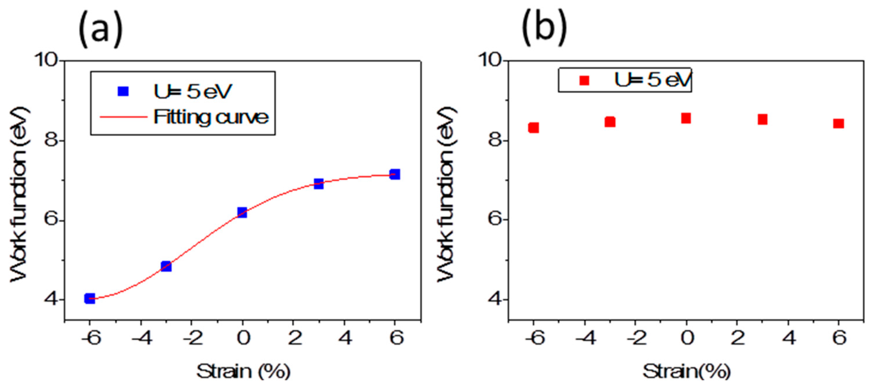
The work function (
W) is calculated as the difference between the vacuum level
Evacuum and the Fermi energy
EF:
W reflects electronic energy level and is therefore related to its electrostatic potential. The strain is an effective approach to modulate the surface work function.
Figure 4a,b presents the electrostatic potential (vacuum level) for the Fe-terminated and O-terminated 1 × 1 × 3 thin film changing with strain increasing, respectively. The vacuum levels (where Fermi energy is set as 0.0 eV) indicate the W relative to upper surfaces. The W for the Fe-terminated surface decreases strongly under compressive strain up to −6%, while it increases obviously under tensile strain up to 6%. For example, it is 4.85 eV under −3% strain with
a = 4.884 Å and 4.04 eV under −6% strain with
a = 4.733 Å, respectively, while it is 6.91 eV under 3% with
a = 5.186 Å and 7.16 eV under 6% strain with
a = 5.337 Å. For O-terminated 1 × 1 × 3 thin film, the W is higher than that of Fe-terminated 1 × 1 × 3 thin films and less sensitive to strain.
It is important to show the mechanism of band gap and W modulations by strain. In this system, the oxygen anions are arranged in an octahedral geometry around the Fe cation. In the crystal field (with ionic approach) of octahedral symmetry, two of the five
d orbitals label
eg with point-symmetry are destabilized and pushed up in energy, and the other three
d orbitals are stabilized and pulled down in energy with the point-symmetry label
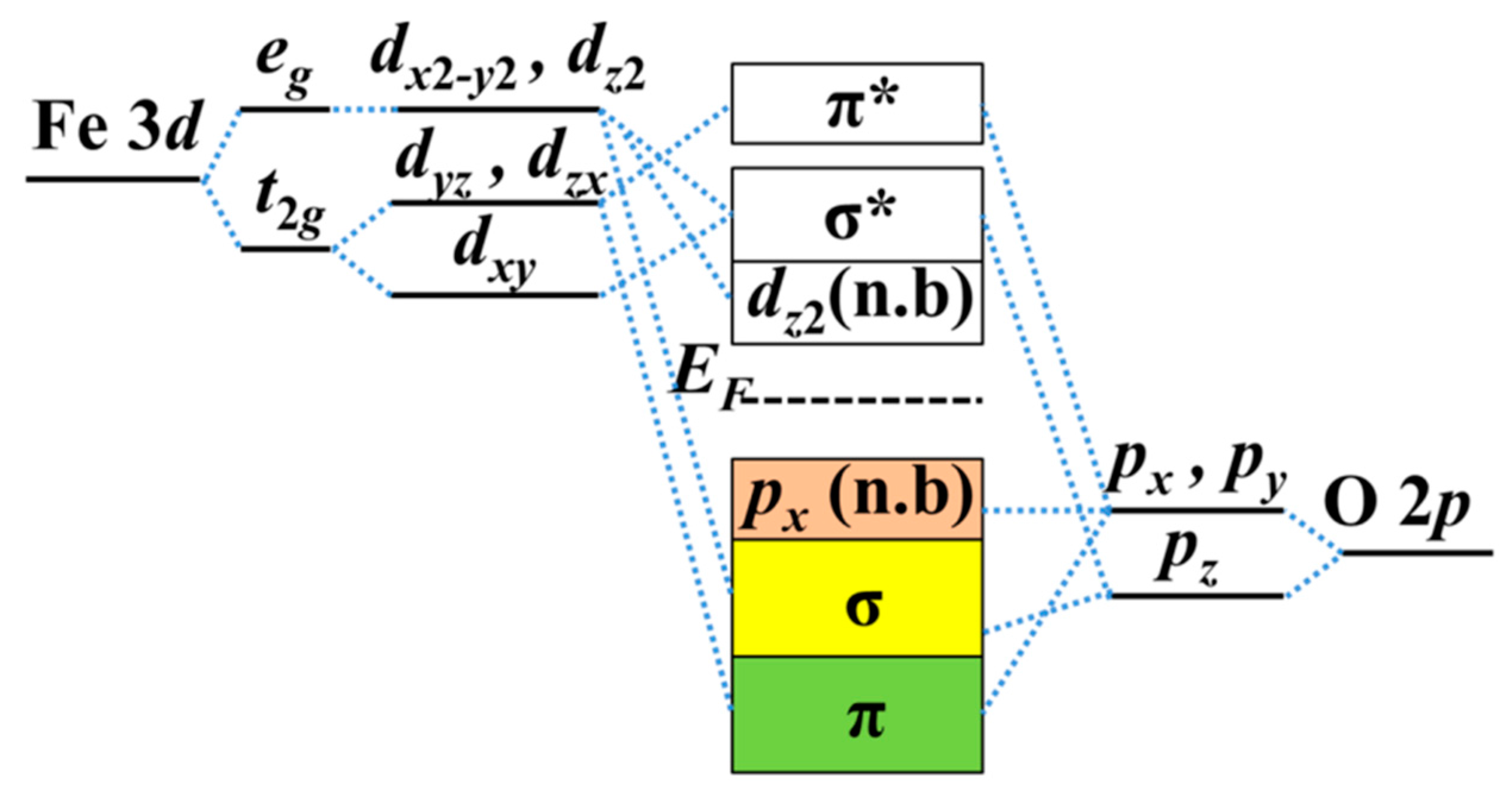
t2g. The schematic diagram of orbital energy-level of Fe
2O
3 is shown in
Figure 5. The σ bonds are formed by head-on overlapping among Fe
dx2-y2,
dz2 and O
pz orbitals, and π bonds are formed by shoulder-on overlapping among Fe
dxy,
dyz,
dyz, and O
px (
py) orbitals. Nonbonding
px (
py) electrons occupy the VBM below
EF. The O
2− molecular orbitals have to be higher than the Fe
3+ orbitals in the isolated system, while below the Fermi level are the orbitals from the O atoms (occupied) and those above are from the Fe (unoccupied) in the α-Fe
2O
3 thin film with the ionic model.
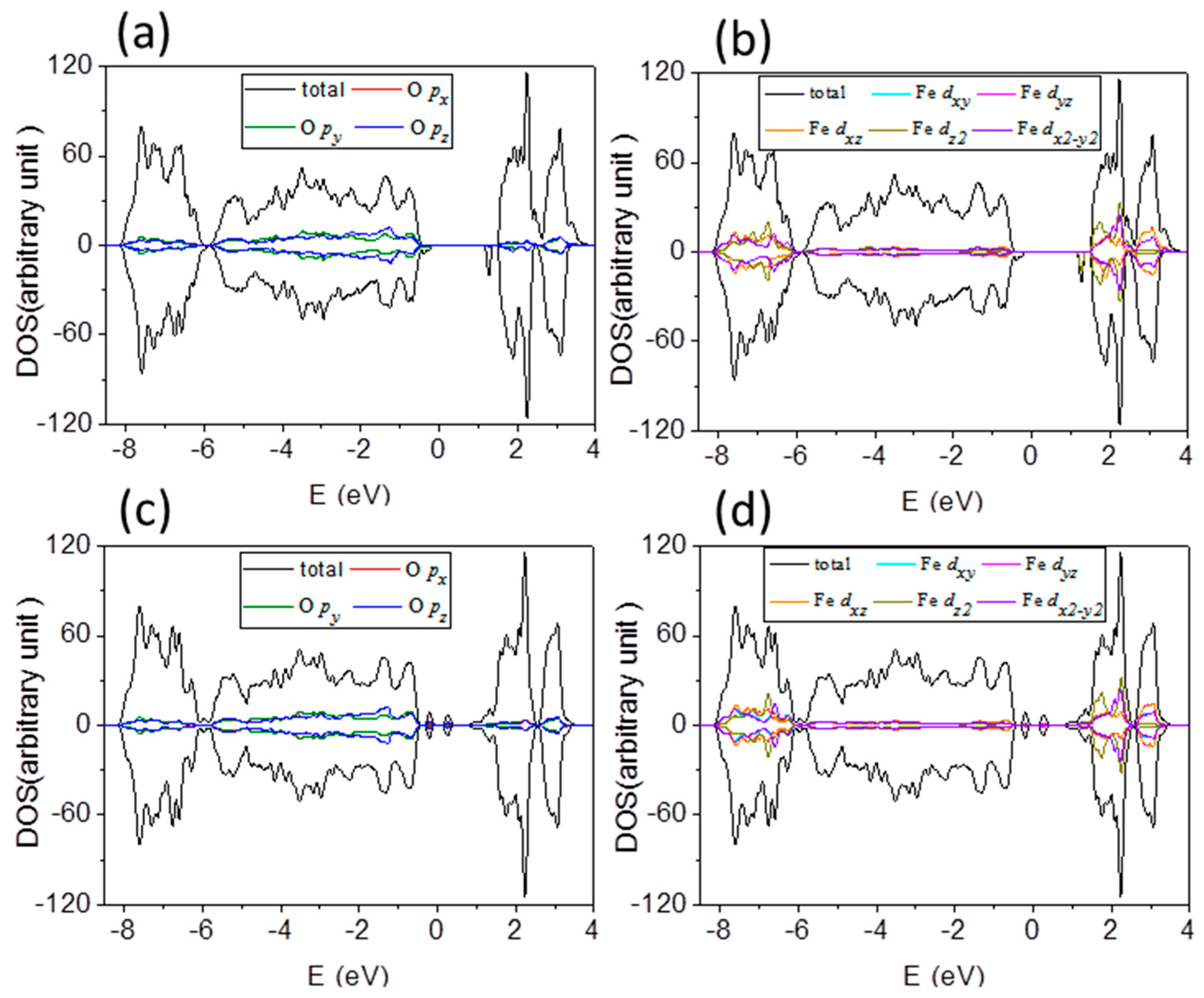
Total density of states (DOS) mainly comes from O 2
p states and Fe
d states. It can be divided into projected DOS plots, as shown in
Figure 6a,b, respectively, for O atom and Fe atom of Fe terminated 1 × 1 × 3 α-Fe
2O
3 films, and labeled in red, olive and blue for
px,
py, and
pz orbitals of O atoms; and cyan, magenta, orange, dark yellow and violet for
dxy,
dyz,
dxz,
dz2 and
dx2 orbitals of Fe atoms. One can see that DOS consist of a hybridized mixture of O and Fe states because overlap integrals between O 2
p states and Fe
d states are nonzero. The contributions from
px and
py states of O atoms to DOS play important role below Fermi level, while DOS above the Fermi level is dominated by Fe 3
d states. Thus, the occupied valence band is majority O 2
p character, and the unoccupied conduction band is majority Fe 3
d character.
Figure 6c,d presents the DOS of O and Fe atoms of O terminated α-Fe
2O
3 films, which reflect
px,
py, and
pz states of O atoms below
EF, and Fe 3
d states are more pronounced above
EF. One can see that it is a charge-transfer type of insulator rather than a Mott–Hubbard insulator, whether it is a Fe or O terminated α-Fe
2O
3 film. In addition to the valence state and the conduction band with significant difference, the shape of the DOS is very similar to that of Fe terminated α-Fe
2O
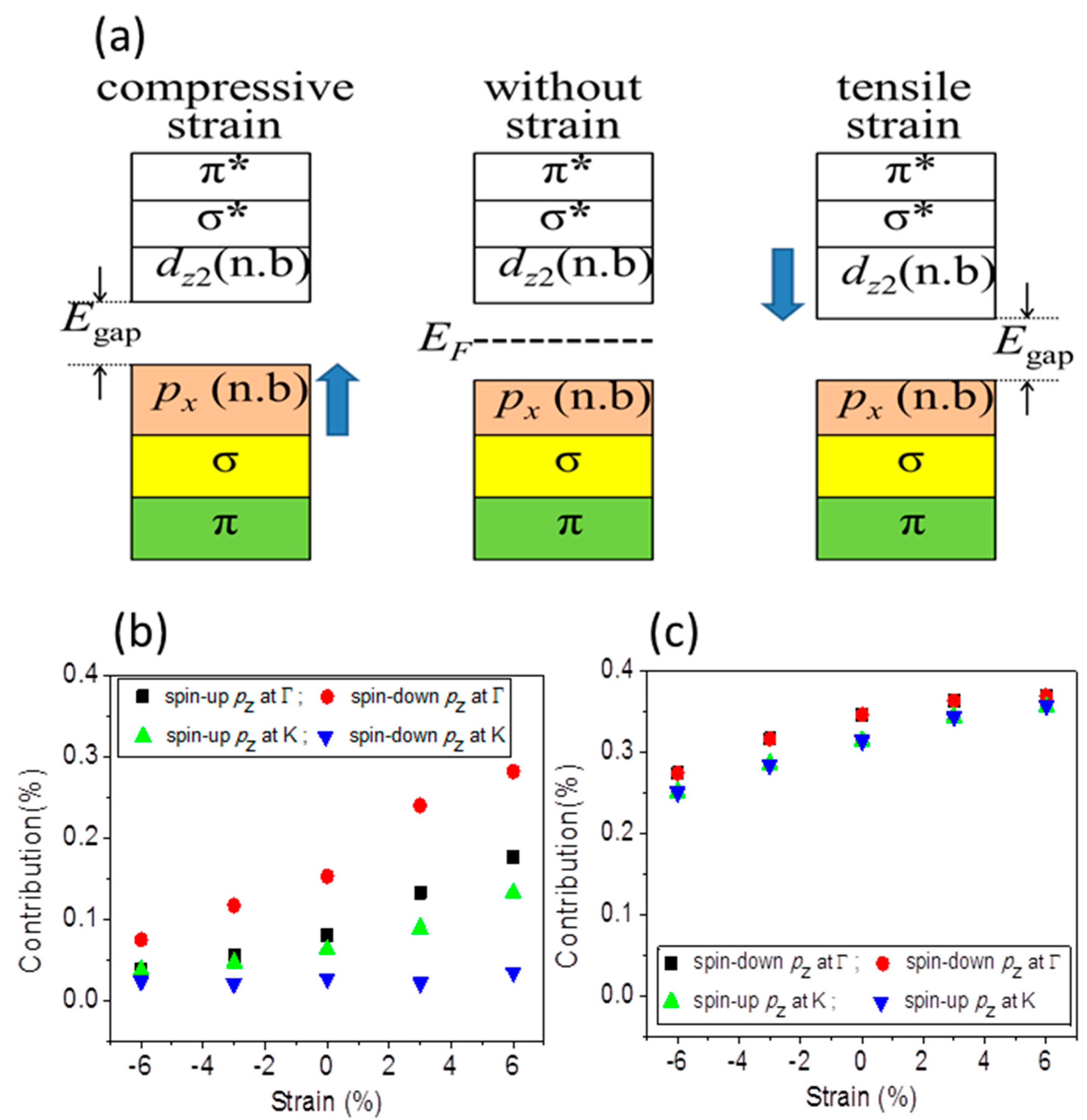
3 films. The mechanism of band gap decreasing under both compressive and tensile strains is similarly in Fe and O terminated α-Fe
2O
3 films. There is a consequence of the fact that the on-site Coulomb potential acts only on the Fe 3
d states, leading to a reduction of the Fe–O hybridization which is too strong under compressive strain. That lifts the degeneracy of Fe
eg orbitals, which competes with the AFM superexchange of localized
t2g electrons. The nonbonding
px and
py states enhance under compressive and then it pushes VBM toward
EF, as seen in
Figure 7a for the schematic diagram of orbital energy-level of Fe
2O
3. Tensile strain lowers the degeneracy of Fe
eg orbitals and the antiferromagnetic superexchange interaction between
t2g spins enhances, which draw CBM with
eg (
dz2) orbitals nearer to
EF. Therefore, under both compressive and tensile strains, the band gap between the VBM and CBM decreases.
The
pz states are strengthened (dropped) under tensile (compressive) strain, as seen in
Figure 7b for Fe terminated α-Fe
2O
3 films. The
pz state with spin down at K point (
Figure 2a,b) is insensitive to strain, which implies the surface state, arising from localized dangling-bond states, while the bulk band, with spin up at K or Γ point, arising from extended Bloch states, is very sensitive to strain. The electrons of
pz state have relatively small momentum because interlayer conduction along the
z-direction is severely suppressed from our results on the basis of very flat conduction band between Γ and A in
Figure 3. With the decrease (increase) of the contribution of the
pz state, the electrons with less momentum decrease (increases), while electrons of
px and
py states with higher momentum increase (decrease), so that the total wave vector and the Fermi sphere radius increase (decrease), the corresponding Fermi energy increase (decrease). Therefore, W reading from Equation (2) decreases under compressive strain and increases under tensile strain. With our results in
Figure 4a, we pbtain the expression of fitting curve for W,
where
x presents the strain. The formula shows the rather complicated relationship between the W and strain. Previous theoretical study has not been well established the relationship between electrostatic potential (or corrosion potential) and mechanical deformation. According to previous studies of the influence of deformation on the electron gas of a metal, it is possible to qualitatively predict changes in the electrode potential [
41] and hence to estimate the effect of deformation on the corrosion potential. Experimental data showed rather complicated relationship and experimental studies have shown that a simple relationship between stress and corrosion parameters does not exist [
42].
For O-terminated 1 × 1 × 3 thin film, the W is higher than that of Fe-terminated 1 × 1 × 3 thin film. The
pz states at Γ and K points are strengthened compared to that of Fe-terminated thin films seen from
Figure 7c under different strain. The electrons of
pz state are more than that of Fe-terminated thin films, whether with or without strain, and, correspondingly, more electrons have small momentum. As a result, the total wave vector and the Fermi sphere radius decreases, and the corresponding Fermi energy decreases. Therefore, W reading from Equation (2) is higher than that of Fe-terminated thin films. Although
pz state at VBM is lowered under compressive strain, it is still more notable than that of Fe-terminated thin films. Moreover, the Fe–O hybridization is stronger than that of Fe-terminated thin film, so electrons are difficult to escape from the surface.
The work function is highly sensitive to surface termination. In particular, the Fe-terminated film significantly drags down work functions under compressive strain. Our results reply that compressive strain lowers the corrosion potential and leads to corrosion easily because the work function is closely related to the corrosion potential and a sensitive parameter to the corrosion behavior. Especially, the W of O-terminated film changes slightly under both compressive and tensile strains, which indicate that strains could not lower the corrosion potential much. It is confirmed that metals are protected from corrosion by the formation of “passive” oxide films.


 ,
, 