
Microstructure Evolution of TiC Particles In Situ, Synthesized by Laser Cladding

Abstract
:
1. Introduction
2. Experiments
3. Results and Discussion
4. Conclusions
Acknowledgments
Author Contributions
Conflicts of Interest
References
- Tjong, S.C.; Ma, Z.Y. Microstructural and Mechanical Characteristics of In Situ Metal Matrix Composites. Mater. Sci. Eng. R 2000, 29, 49–113. [Google Scholar] [CrossRef]
- Lekatou, A.; Karantzalis, A.E.; Evangelou, A.; Gousia, V.; Kaptay, G.; Gacsi, Z.; Baumli, P.; Simon, A. Aluminium reinforced by WC and TiC nanoparticles (ex-situ) and aluminide particles (in-situ): Microstructure, wear and corrosion behaviour. Mater. Des. 2015, 65, 1121–1135. [Google Scholar] [CrossRef]
- Attar, H.; Bönisch, M.; Calin, M.; Zhang, L.C.; Scudino, S.; Eckert, J. Selective laser melting of in situ titanium—Titanium boride composites: Processing, microstructure and mechanical properties. Acta Mater. 2014, 76, 13–22. [Google Scholar] [CrossRef]
- Sandor, T.; Mekler, C.; Dobranszky, J.; Kaptay, G. An Improved Theoretical Model for A-TIG Welding Based on Surface Phase Transition and Reversed Marangoni Flow. Metall. Mater. Trans. A 2013, 44A, 351–361. [Google Scholar] [CrossRef]
- Chen, D.; Liu, D.; Liu, Y.; Wang, H.; Huang, Z. Microstructure and fretting wear resistance of gamma/TiC composite coating in situ fabricated by plasma transferred arc cladding. Surf. Coat. Technol. 2014, 239, 28–33. [Google Scholar] [CrossRef]
- He, J.; Zhang, B.G.; Li, W.L. The dependence of the electron beam remelting parameters on the surface residual stress and hardness of NbSi2 coatings on niobium alloys. J. Alloys Compd. 2013, 577, 436–438. [Google Scholar] [CrossRef]
- AlMangour, B.; Grzesiak, D.; Yang, J.-M. Nanocrystalline TiC-reinforced H13 steel matrix nanocomposites fabricated by selective laser melting. Mater. Des. 2016, 96, 150–161. [Google Scholar] [CrossRef]
- Zhang, H.; Zou, Y.; Zou, Z.; Zhao, W. Comparative study on continuous and pulsed wave fiber laser cladding in-situ titanium–vanadium carbides reinforced Fe-based composite layer. Mater. Lett. 2015, 139, 255–257. [Google Scholar] [CrossRef]
- Verezub, O.; Kálazi, Z.; Buza, G.; Verezub, N.V.; Kaptay, G. Classification of laser beam induced surface engineering technologies and in situ synthesis of steel matrix surface nanocomposites. Surf. Eng. 2011, 27, 428–435. [Google Scholar] [CrossRef]
- Limmaneevichitr, C.; Kou, S. Experiments to simulate effect of Marangoni convection on weld pool shape. Weld. Res. Suppl. 2000, 79, 231–237. [Google Scholar]
- Jiao, L.G.; Li, J.S.; Yuan, C.; Jiang, H.M.; Zhao, G.M. Irradiation effects of continuous laser on liquid tank: A natural convection study. Int. J. Heat. Mass. Transf. 2014, 77, 970–978. [Google Scholar] [CrossRef]
- Michael, F.G.; Jarred, C.H.; Panagiotis, M.; Todd, A.P. Modeling forced convection in the thermal simulation of laser cladding processes. Int. J. Adv. Manuf. Technol. 2015, 79, 307–320. [Google Scholar]
- Lee, Y.; Nordin, M.; Babu, S.S.; Farson, D.F. Effect of Fluid Convection on Dendrite Arm Spacing in Laser Deposition. Metall. Mater. Trans. B 2014, 45B, 1520–1529. [Google Scholar] [CrossRef]
- Shuja, S.Z.; Yilbas, B.S. Laser produced melt pool: Influence of laser intensity parameter on flow field in melt pool. Opt. Laser Technol. 2014, 43, 767–775. [Google Scholar] [CrossRef]
- Dahotre, N.B.; Mukherjee, K. Development of microstructure in laser surface alloying of steel with chromium. J. Mater. Sci. 1990, 25, 445–454. [Google Scholar] [CrossRef]
- Bartkowski, D.; Kinal, G. Microstructure and wear resistance of Stellite-6/WC MMC coatings produced by laser cladding using Yb: YAG disk laser. Int. J. Refract. Met. Hard Mater. 2016, 58, 157–164. [Google Scholar] [CrossRef]
- Drezet, J.M.; Pellerin, S.; Bezencon, C.; Mokadem, S. Modelling the Marangoni convection in laser heat treatment. J. Phys. IV 2004, 120, 299–306. [Google Scholar]
- Limmaneevichitr, C.; Kou, S. Visualization of Marangoni convection in simulated weld pools. Weld. Res. Suppl. 2000, 79, 126–135. [Google Scholar]
- Qi, Q.; Liu, Y.; Zhang, H.; Zhao, J.; Gai, L.; Huang, Y.; Huang, Z. The formation mechanism of TiC particles in TiC/Ni composites fabricated by in situ reactive infiltration. J. Mater. Sci. 2016, 51, 7038–7045. [Google Scholar] [CrossRef]
- Ya, B.; Zhou, B.; Yang, H.; Huang, B.; Jia, F.; Zhang, X. Microstructure and mechanical properties of in situ casting TiC/Ti6Al4V composites through adding multi-walled carbon nanotubes. J. Alloys Compd. 2015, 637, 456–460. [Google Scholar] [CrossRef]
- Huang, S.; Sun, D.; Wang, W.; Xu, H. Microstructures and properties of in-situ TiC particles reinforced Ni-based composite coatings prepared by plasma spray welding. Ceram. Int. 2015, 41, 12202–12210. [Google Scholar] [CrossRef]
- AlMangour, B.; Grzesiak, D.; Yang, J.M. Selective laser melting of TiC reinforced 316L stainless steel matrix nanocomposites: Influence of starting TiC particle size and volume content. Mater. Des. 2016, 104, 141–151. [Google Scholar] [CrossRef]
- Jin, C.; Plucknett, K.P. Microstructure instability in TiC-316L stainless steel cermets. Int. J. Refract. Met. Hard Mater. 2016, 58, 74–83. [Google Scholar] [CrossRef]
- Yu, H.L.; Zhang, W.; Wang, H.M.; Ji, X.C.; Song, Z.Y.; Li, X.Y.; Xu, B.S. In-situ synthesis of TiC/Ti composite by high frequency induction cladding. J. Alloys Compd. 2017, 701, 244–255. [Google Scholar] [CrossRef]
- AIMangour, B.; Grzesiak, D.; Yang, J.-M. In-situ formation of novel TiC-particle-reinforced 316L stainless steel bulk-form composites by selective laser melting. J. Alloys Compd. 2017, 706, 409–418. [Google Scholar] [CrossRef]
- Borkar, T.; Sosa, J.; Hwang, J.Y.; Scharf, T.W.; Tiley, J.; Fraser, H.; Banerjee, R. Laser-Deposited In Situ TiC-Reinforced Nickel Matrix Composites: 3D Microstructure and Tribological Properties. JOM 2014, 66, 935–942. [Google Scholar] [CrossRef]
- Li, Q.; Lei, Y.; Fu, H. Growth mechanism, distribution characteristics and reinforcing behavior of (Ti, Nb)C particle in laser cladded Fe-based composite coating. Appl. Surf. Sci. 2014, 316, 610–616. [Google Scholar] [CrossRef]
- Liu, Y.H.; Li, J.; Xuan, F.Z. Fabrication of TiC reinforced Ni based coating by laser cladding. Surf. Eng. 2012, 28, 560–563. [Google Scholar] [CrossRef]
- Bandyopadhyay, D.; Sharma, R.C.; Chakraborti, N. The Ti-Ni-C System. J. Phase Equilib. 2000, 21, 186–191. [Google Scholar] [CrossRef]
- Wang, X.; Ding, H.; Qi, F.; Liu, Q.; Fan, X.; Shi, Y. Mechanism of in situ synthesis of TiC in Cu melts and its microstructures. J. Alloys Compd. 2017, 695, 3410–3418. [Google Scholar] [CrossRef]


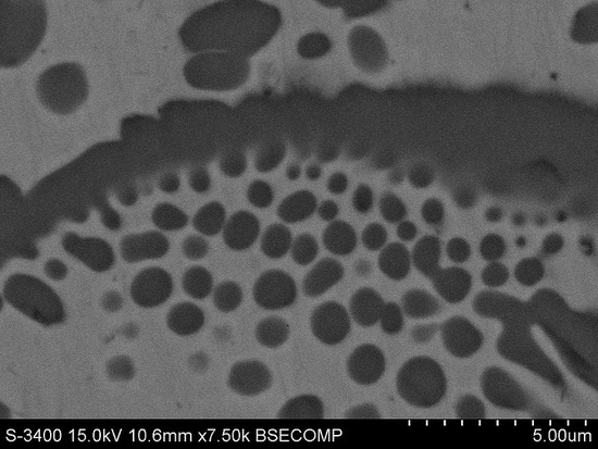
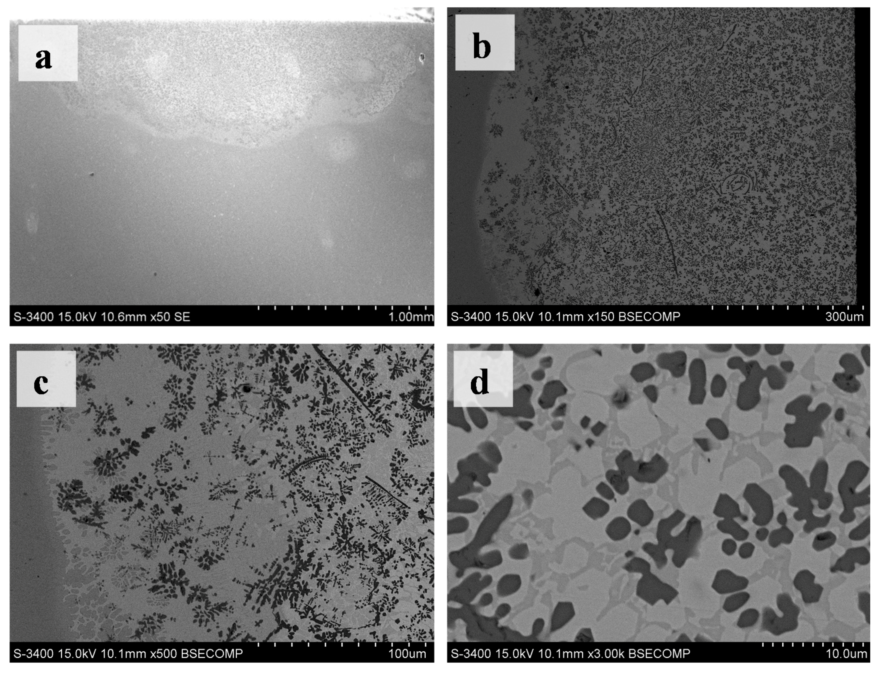
| Test Zone | Ni (at %) | Ti (at %) | C (at %) | Al (at %) | Matrix |
|---|---|---|---|---|---|
| Grey white zone | 75.95 | 20.06 | - | 3.99 | ZAF |
| Grey zone | 54.39 | 42.16 | - | 3.45 | ZAF |
| Black zone | 2.63 | 40.31 | 57.06 | - | ZAF |
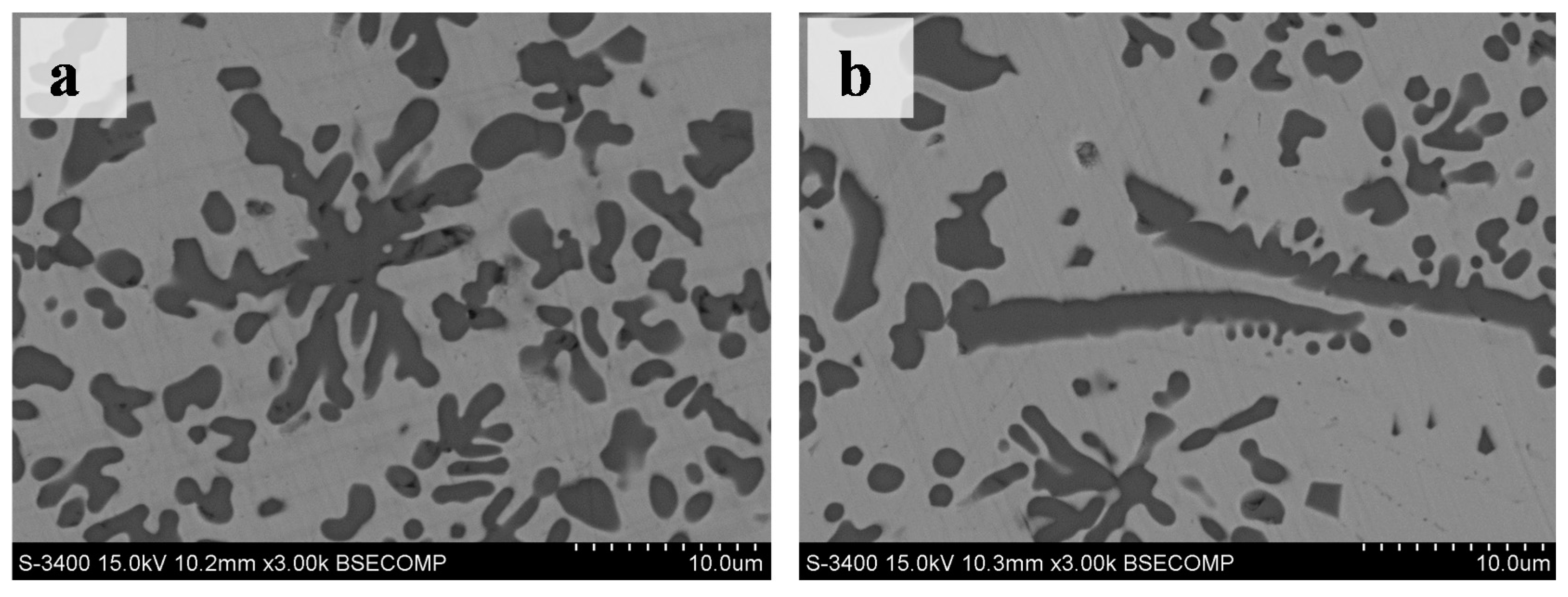
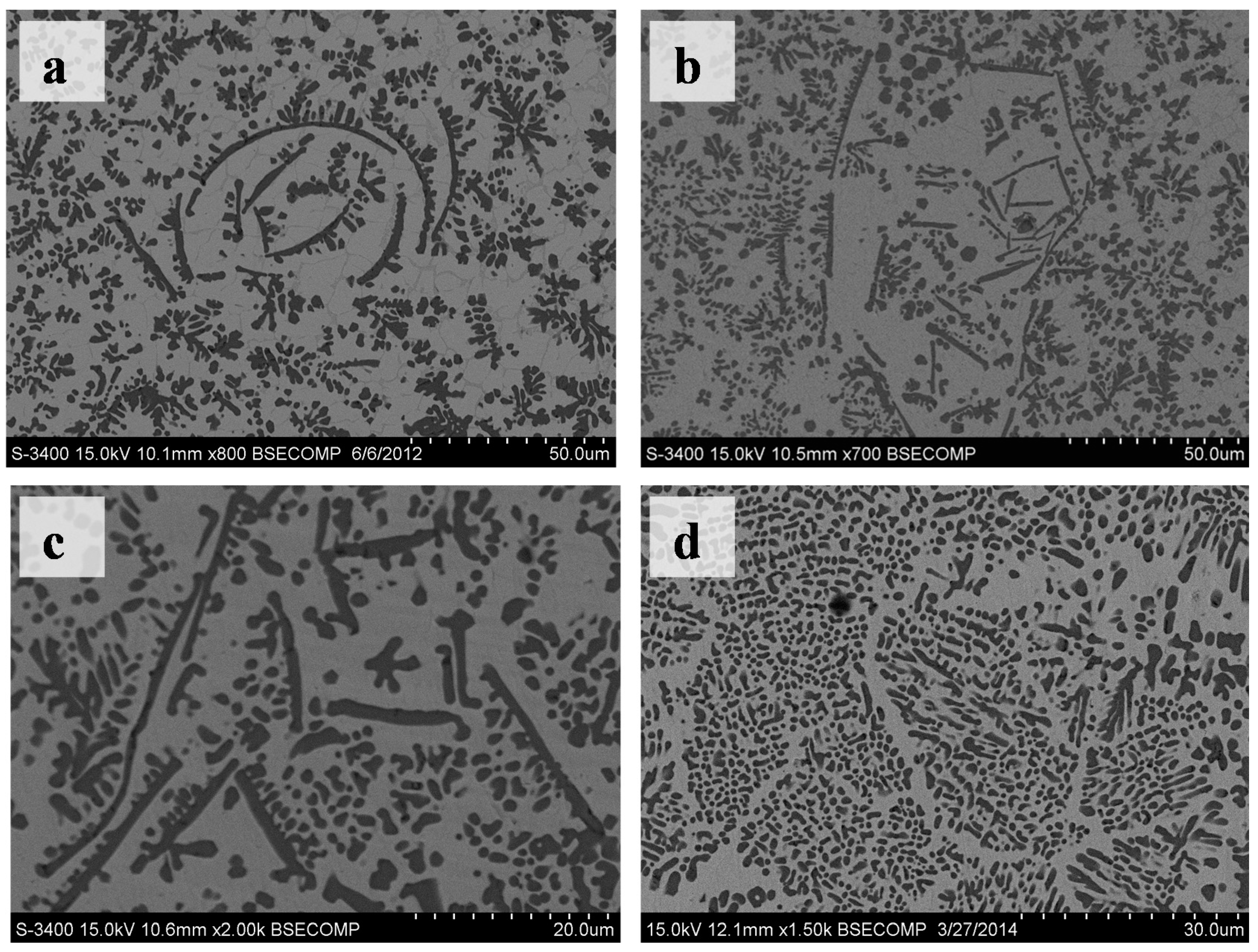
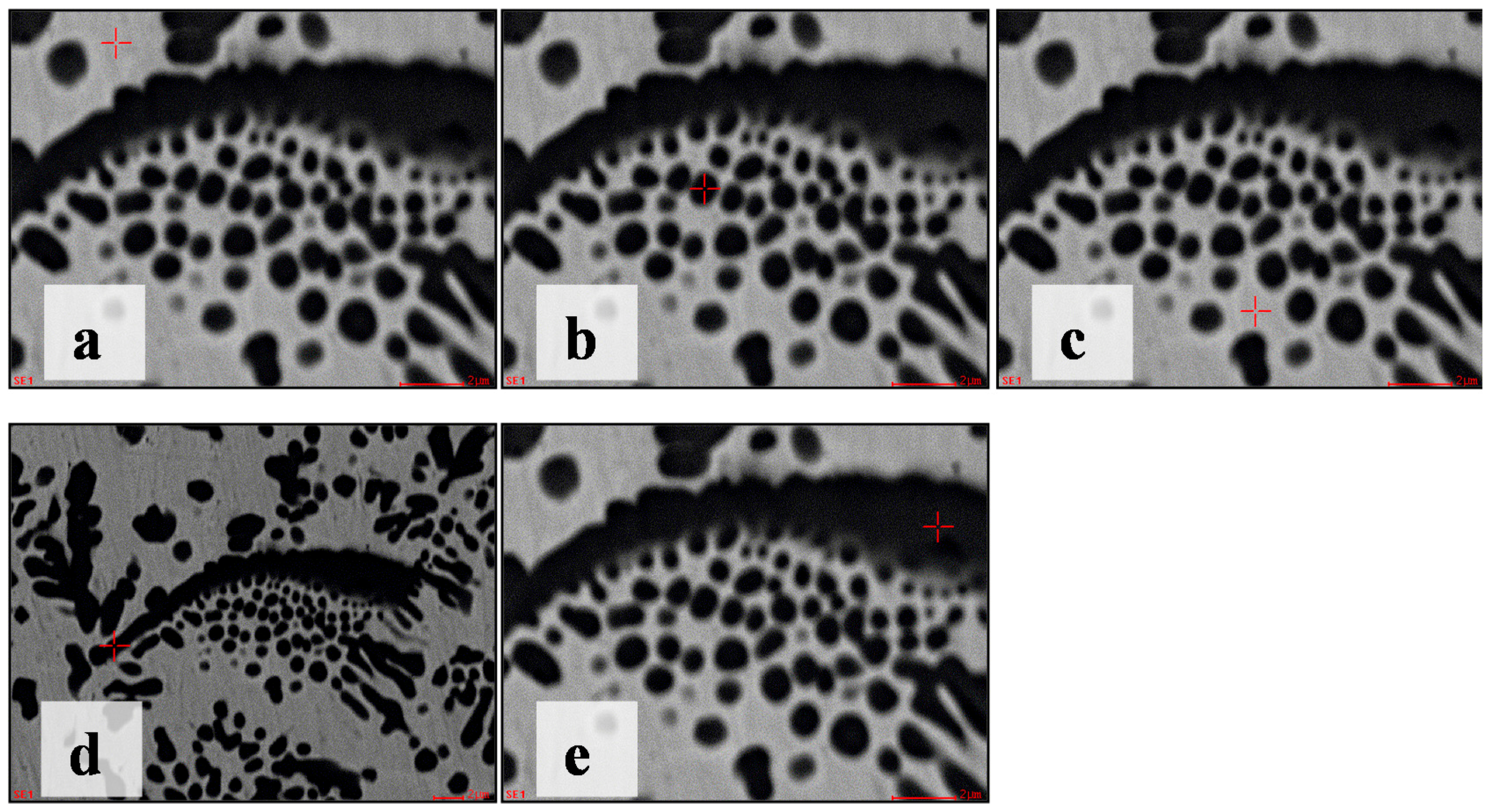
| No. | C (at %) | Ti (at %) | Ni (at %) | Al (at %) | Matrix |
|---|---|---|---|---|---|
| a | 37.09 | 9.37 | 49.57 | 3.97 | ZAF |
| b | 59.96 | 32.63 | 7.00 | 0.42 | ZAF |
| c | 54.25 | 24.73 | 19.81 | 1.21 | ZAF |
| d | 64.58 | 27.05 | 7.82 | 0.56 | ZAF |
| e | 63.19 | 35.23 | 1.58 | - | ZAF |
© 2017 by the authors. Licensee MDPI, Basel, Switzerland. This article is an open access article distributed under the terms and conditions of the Creative Commons Attribution (CC BY) license ( http://creativecommons.org/licenses/by/4.0/).
Share and Cite
Liu, Y.; Ding, J.; Qu, W.; Su, Y.; Yu, Z. Microstructure Evolution of TiC Particles In Situ, Synthesized by Laser Cladding. Materials 2017, 10, 281. https://doi.org/10.3390/ma10030281
Liu Y, Ding J, Qu W, Su Y, Yu Z. Microstructure Evolution of TiC Particles In Situ, Synthesized by Laser Cladding. Materials. 2017; 10(3):281. https://doi.org/10.3390/ma10030281
Chicago/Turabian StyleLiu, Yanhui, Jieqiong Ding, Weicheng Qu, Yu Su, and Zhishui Yu. 2017. "Microstructure Evolution of TiC Particles In Situ, Synthesized by Laser Cladding" Materials 10, no. 3: 281. https://doi.org/10.3390/ma10030281