Flexural and Free Vibration Analysis of CNT-Reinforced Functionally Graded Plate


1
Department of Civil Engineering, National Institute of Technology, Patna, Patna-800005, India
2
Faculty of Civil Engineering and Architecture, Lublin University of Technology, 40 Nadbystrzycka Str., 20-618 Lublin, Poland
*
Author to whom correspondence should be addressed.
Materials 2018, 11(12), 2387; https://doi.org/10.3390/ma11122387
Submission received: 22 October 2018
/
Revised: 16 November 2018
/
Accepted: 23 November 2018
/
Published: 27 November 2018
(This article belongs to the Special Issue Behavior of Metallic and Composite Structures)
Abstract
:This paper examines the effect of uniaxially aligned carbon nanotube (CNT) on flexural and free vibration analysis of CNT-reinforced functionally graded plate. The mathematical model includes expansion of Taylor’s series up to the third degree in the thickness co-ordinate. Since there is a parabolic variation in transverse shear strain deformation across the thickness co-ordinate, the shear correction factor is not necessary. A nine-node two-dimensional (2D) C0 isoparametric element containing seven nodal unknowns per node was developed in the finite element code. The final material properties of CNT-reinforced functionally graded plate are estimated using the extended rule of mixture. The effect of CNT distribution, boundary condition, volume fraction and loading pattern are studied by developing a finite element code. An additional finite element code was developed for the study of the influence of concentrated mass on free vibration analysis of CNT-reinforced functionally graded plate.
1. Introduction
In the modern age, carbon nanotube (CNT)-reinforced composite plates have found considerable application in civil, mechanical, aeronautical and marine engineering due to their exceptional mechanical, thermal and electrical properties. The high tensile properties of CNT make CNT-reinforced composites preferable in tension-dominated applications such as pressure vessels. The concentrated mass is generally used to reduce the fundamental frequency to the desired value. The CNTs are allotropes of carbon having a length scale in the order of nanometres discovered by Iijima [1], having higher strength/weight ratio and lower density. Due to their superior properties, the CNTs are substantially preferable as a reinforcing choice for advanced composites. The Eshelby-Mori-Tanaka approach and a 2-D generalised differential quadrature method was used by Aragh et al. [2] for the frequency analysis of continuously graded CNT-reinforced cylindrical panel. The effect of singly walled carbon nanotubes (SWCNTs) on bending and vibration analysis of CNT-reinforced functionally graded (FG-CNT) plate was studied by Zhu et al. [3] with the help of the finite element method. Their mathematical model is based on the first order shear deformation theory (FSDT). Yas et al. [4] developed a three-dimensional model to study the vibration behaviour of functionally graded cylindrical panel reinforced with CNT. The element-free kp-Ritz method was used by Lei et al. [5] to study the free vibration analysis of CNT-reinforced composite (CNTRC) plate assuming an FSDT based displacement field. The deflection and stresses developed in CNT-reinforced composite cylinders have been studied by Dastjerdi et al. [6] using the mesh-free method. The FSDT-based displacement model was adopted by Zhang et al. [7] to analyse the flexural and free vibration response of CNT-reinforced composite panel. The Eshelby–Mori–Tanaka approached was used by them to calculate the final properties of CNT-reinforced cylindrical panel. The ending behaviour of FG-CNTRC cylindrical shell under mechanical loading was studied by Mehrabadi and Aragh [8]. They also incorporated the Eshelby–Mori–Tanaka approach, to calculate the effective material properties of uniformly distributed (UD) and FG-CNT-reinforced cylindrical shell. Budarapu et al. [9] developed a method to calculate the natural frequencies of multi-walled CNT embedded in an elastic medium. The higher order shear deformation theory (HSDT) is used by Sankar et al. [10] to study the static and free vibrations of FG-CNTRC plates and sandwich plates. Nami and Janghorban [11] used a three-dimensional elastic theory to analyse the free vibration behaviour of FG-CNTRC plate. Zhang et al. [12] explored the behaviour of CNT-reinforced plate with elastically restrained edges, using the element-free Ritz method incorporating FSDT, while Macias et al. [13] used FSDT along with a four-noded shell element for the investigation of CNT-reinforced functionally graded skew plate. Zhang and Selim [14] and Selim et al. [15] have both used Reddy’s HSDT displacement field for the dynamics analyses of FG-CNT-reinforced composite plate. The vibration analysis of doubly curved composite shell panel reinforced with CNT was studied by Pouresmaeell and Fzelzadeh [16]. Tornabene et al. [17] and Fantuzzi [18] adopted a micro-mechanical model for the study of dynamic behaviour of FG-CNT-reinforced arbitrary shaped plate and shell. They used Non-Uniform Rational B-Splines (NURBS) curves to obtain the arbitrary shape. Banic et al. [19] explored the vibration behaviour of composite plate and shell, reinforced with agglomerated CNT, which rested on Winkler–Pasternak elastic foundation. The mechanical properties are estimated using a modified rule of mixture. The non-linear thermo-elastic frequency analysis of CNT-reinforced functionally graded single and doubly curved shell has been carried out by Mehar et al. [20]. The FSDT was used by Huang et al. [21] to study the bending and free vibration behaviour of laminated CNT-reinforced plate. They have used the extended rule of mixture to compute the effective properties of material and adopted four-variable theories for a mathematical model. Asadi et al. [22] discussed the aero-thermo-elastic behaviour of supersonic FG-CNTRC flat panel in a thermal environment. The model is based on the FSDT incorporated with the von Karman geometric non-linearity. The experimental, numerical and simulation model for deflection behaviour of CNTRC plate was developed by Mehar and Panda [23]. Demirbas [24] developed an elastic theory for thermal analysis of functionally graded material (FGM) plate subjected to in-plane constant heat flux. Tornabene et al. [25] used FSDT and the generalised differential quadrature method to analyse the free vibration behaviour of laminated nano-composite plate and shell. They modelled each layer of the laminate as a three-phase composite. Size-dependent analysis of functionally graded microplate by using isogeometric analysis is studied by Liu et al. [26,27].
The static and free vibration analysis of an FG-CNT-reinforced plate will be complex using elastic solution or analytical method [15,28,29,30,31]. Apart from this, the elastic and analytical solutions are more difficult to obtain for complex boundary conditions. Therefore, in this paper, an effort has been made for the behavioural study of the CNT-reinforced functionally graded plate for various combinations of end support using third order shear deformation theory (TSDT), which omit the necessity of the shear correction factor. To the best of authors knowledge, no work has been done on flexural and free vibration analysis of FG-CNT-reinforced plate using 2D C0 finite element (FE) model using TSDT. In present analysis 2D C0 model is adopted along with finite element method which are more convenient due to the low computational effort requirement. The effective material properties of FG-CNT-reinforced plates are estimated using the extended rule of mixture. Three FE coding (static analysis, free vibration analysis and free vibration analysis with concentrated mass) were developed by the authors for the current model. Since there are no available results in the literature for the bending of FG-CNT-reinforced composite plates subjected to trigonometrical loading, and free vibration analysis of FG-CNT-reinforced composite plate with concentrated mass, hence the present analyses results may be useful for scholars working in this field. The mode shapes of CNT-reinforced plates are also plotted using MATLAB coding (MathWorks, Natick, MA, USA).
2. Effective Material of CNT-reinforced Functionally Graded Plates
In the present analysis, the geometry of CNT-reinforced plates is depicted in Figure 1 and is referred to the co-ordinates system. The FG-CNT-reinforced plate has a constant thickness h, with the length of the plate a, and width b. In this work, three types of functionally graded distribution (FG-O, FG-X and FG-V) and uniformly distributed (UD) of SWCNTs in polymer matrix across the thickness direction is considered. The extended rule of mixture [32,33], which contains the efficiency parameters, is incorporated for the calculation of effective material properties of the FG-CNT-reinforced composite plate.
3. Theoretical Formulation
3.1. Displacement Fields and Strains
Based on the third-order shear deformation theory, the displacement field (u,v,w) can be determined as follows [34]:
where are the displacements along the directions, respectively, at the mid-plane . are the bending rotations about the and axes, respectively. are known as the higher order terms of Taylor’s series expansion. The unknown terms are computed by applying zero shear stress at the lower and upper surfaces of a CNT-reinforced plate. Utilising the boundary conditions at the top and bottom surfaces of the plate in Equation (7), we obtained Taylor’s series expansion terms as
Substituting Equation (8) into Equation (7), we obtain
During the implementation of the displacement field represented in Equation (10), the problem of C1 continuity is encountered due to the presence of first order derivatives of the transverse displacement component in the expression of in-plane fields. For applying efficient C0 FE formulation, the derivatives are replaced by the appropriate substitution of an independent nodal unknowns as
The higher order displacement field owning C0 continuity can express as:
Hence, the degree of freedom (basic field variables) according to present mathematical formulation for each node is
where is named as the displacement vector.
The strain vector from the above displacement field can be written as
Further, the relations between the strain vector and the displacement vector can be expressed as
where the strain-displacement matrix [B] contains the derivatives of shape function.
The in-plane and transverse shear strains are
The strain relationships can be written as
where, , , , , , , , , , , , , .
3.2. Constitutive Relations
The linear stress-strain constitutive relationships for the CNT-reinforced plate are
where the constitutive matrix
The term can be obtained from the material properties which are the function of the depth of the plate.
4. Finite Element Method
4.1. Element Description
For the present C0 finite element (FE) model, nine-node isoparametric Lagrangian elements with node-wise seven degrees of freedom are employed. The shape function (interpolation function) is used to express the generalised displacement vector and element geometry at any point within an element as:
where Ni is the shape function of nine-node isoparametric Lagrangian elements [35].
4.2. Flexural Analysis
The strain energy may be expressed as
By using the Equation (18), the above expression can be represented as
where in which [H] matrix contains φ and h.
The global stiffness matrix is derived by minimising the total energy of the CNT-reinforced plate as
By using the standard procedure, the FE equations of CNT-reinforced plates subjected to transverse load can be expressed as
where and are load vector and global stiffness matrix.
4.3. Free Vibration Analysis
The governing equation of free vibration analysis of CNT-reinforced plates is expressed as
where [K] and [M] are the global stiffness matrix and global mass matrix, respectively. The global stiffness matrix [K] is the same as expressed in Equation (24).
The element mass matrix shown below is derived by applying Hamilton’s principle.
where matrix [C] matrix contains shape function (Ni).
The [L] matrix can be stated as:
where the matrix [F] of order 3 × 7 contains φ and some constant quantities like that of [H] and ρ is known as the density which will be calculated from Equation (5).
5. Numerical Result and Discussion
In this section, many numerical examples were studied for the flexural and free vibration behaviour of CNT-reinforced functionally grade plates. PmPV [36] was for the matrix and for reinforcing the material armchair (10,10) SWCNTs were chosen. The material properties of SWCNT and the matrix at room temperature (300 K) are given as
The CNT efficiency parameters for considered three types of volume fraction are given as:
The quantities used in the present study are:
For the flexural analysis
For the free vibration analysis
Concentrated mass
The loading patterns are used as:
The details of end support conditions used in the present study are:
1. Clamped (CCCC):
2. Simply supported (SSSS):
3. Clamped and simply supported (CCSS):
Convergence and Validation Study
To check the suitable number of mesh sizes to attain precise results, a convergence study was performed for both flexural and free vibration analyses of CNT-reinforced functionally graded plates. Table 1 and Table 2 show the convergence study for the fundamental frequency and deflection of a clamped FG-CNT-reinforced plate. The results are computed for and a/h = 10 for different mesh sizes. These convergence studies highlighted that for free vibration analysis and bending analysis of FG-CNT-reinforced plates, a 16 × 16 mesh size is satisfactory. Table 3 shows the results of the free vibration analyses for an isotropic square plate (ν = 0.3). The dimensionless frequency parameter of the isotropic plate was compared with HSDT results for a moderately thick plate [37] and an exact solution [38]. For more investigation, a detailed comparison has been done for free vibration and bending analyses considering three thickness ratios (a/h = 10, 20 and 50) and three volume fractions . The calculated frequency parameter shown in Table 4 and Table 5 for simply supported boundary conditions are in line with previous result provided by Zhu et al. [3]. Table 6 shows the central deflection of the UD reinforced composite plate for CCCC, SSSS, SCSC and SFSF boundary conditions. Our numerical results confirm with previous result given by Zhu et al. [3].
Afterwards, the parametric studies have been conducted to examine the effect of boundary conditions (SSSS, CCCC, CCSS, CSCS, CCFF and CFCF), thickness ratios (a/h), concentrated mass, as well as, the volume fraction of CNT on the flexural and free vibration behaviour of CNT-reinforced functionally graded plate. The non-dimensional frequency of the first six modes for FG-CNT-reinforced plate is presented in Table 7, Table 8 and Table 9 for the three-different types of , respectively. The results are computed for a/b = 1 and a/h = 10. For the all considered boundary conditions, minimum and maximum non-dimensional frequency parameters were noted for FG-O and FG-X distribution among the other considered distribution. Rather than mid-section, the top and bottom section of the plate was chosen for the distribution of additional CNT to achieve maximum stiffness. Thus, the FG-O and FG-X distributions produce minimum and maximum stiffness, respectively. Further, it was also noticed that CFCF yields minimum frequency parameters while the all side-clamped plate yields the maximum frequency parameter. This is because the higher constraints at the boundary give a higher stiffness to the CNT-reinforced functionally graded plate. Here, approximately, a 6% increase in non-dimensional fundamental frequency was noticed when the volume fraction of CNT increases from 0.11 to 0.14, around a 25% increase was noticed when changes from 0.11 to 0.17.
Figure 2 shows the effect of side-to-thickness ratio on the non-dimensional fundamental frequency of FG-CNT-reinforced plates. The results are calculated for = 0.17 for CCSS, CSCS, CCFF and CFCF boundary conditions. Here it can be seen that the dimensionless frequency parameters increase along with the a/h ratio and it became insensitive from a/h = 60 onwards for all used boundary conditions. The effect of the concentrated mass on the free vibrations of FG-CNT-reinforced plates, having simply supported boundary conditions, is presented in Table 10. It can be noticed that increases in concentrated mass at the centre decreases the fundamental frequency parameter while no significant reduction is seen for any other mode of frequencies. Here, an approximate 28% decrease in the fundamental frequency is noticed when the value of the concentrated mass is increased by 0.5–1 and 1–2.
Figure 3 shows the effect of concentrated mass on the vibration behaviour of an FG-CNTRC plate having various types of boundary conditions. For all considered boundary conditions, the dimensionless frequency parameter decreases, with an increase in the concentrated mass; and the CFCF boundary conditions have the least effect of concentration among considered boundary conditions. The first mode shape of a UD-CNT-reinforced plate, with concentrated mass at the centre, is presented in Figure 4.
The maximum deflection of an FG-CNT-reinforced plate having various side-to-thickness ratios for subjected to sin-sin loading are presented in Table 11, Table 12 and Table 13, respectively. The results are calculated for UD, FG-V, FG-O and FG-X distribution of CNT across the transverse direction, having an aspect ratio a/b = 1. A decrease in deflection is noted when the increases because of the higher value of , imparts a higher stiffness in CNT-reinforced plate, thus the deflection is reduced. The maximum deflection decreases with an increase in the a/h ratio irrespective of boundary conditions and types of distribution. Our finding confirms that there is approximately a 7% reduction in the maximum deflection for all considered end support as the value of increased from 0.11 to 0.14 and approximately a 36% decrease is found when increases from 0.11 to 0.17. FG-X and FG-O distribution yields minimum and maximum deflection, respectively.
Figure 5 shows the variation of deflection of UD, FG-V, FG-O and FG-X type CNT-reinforced plates along the centre line subject to the various types of mechanical load. The results are obtained for . It can be seen that, for all types of CNT distribution in the thickness direction, the graph of deflection along the length is of the same nature.
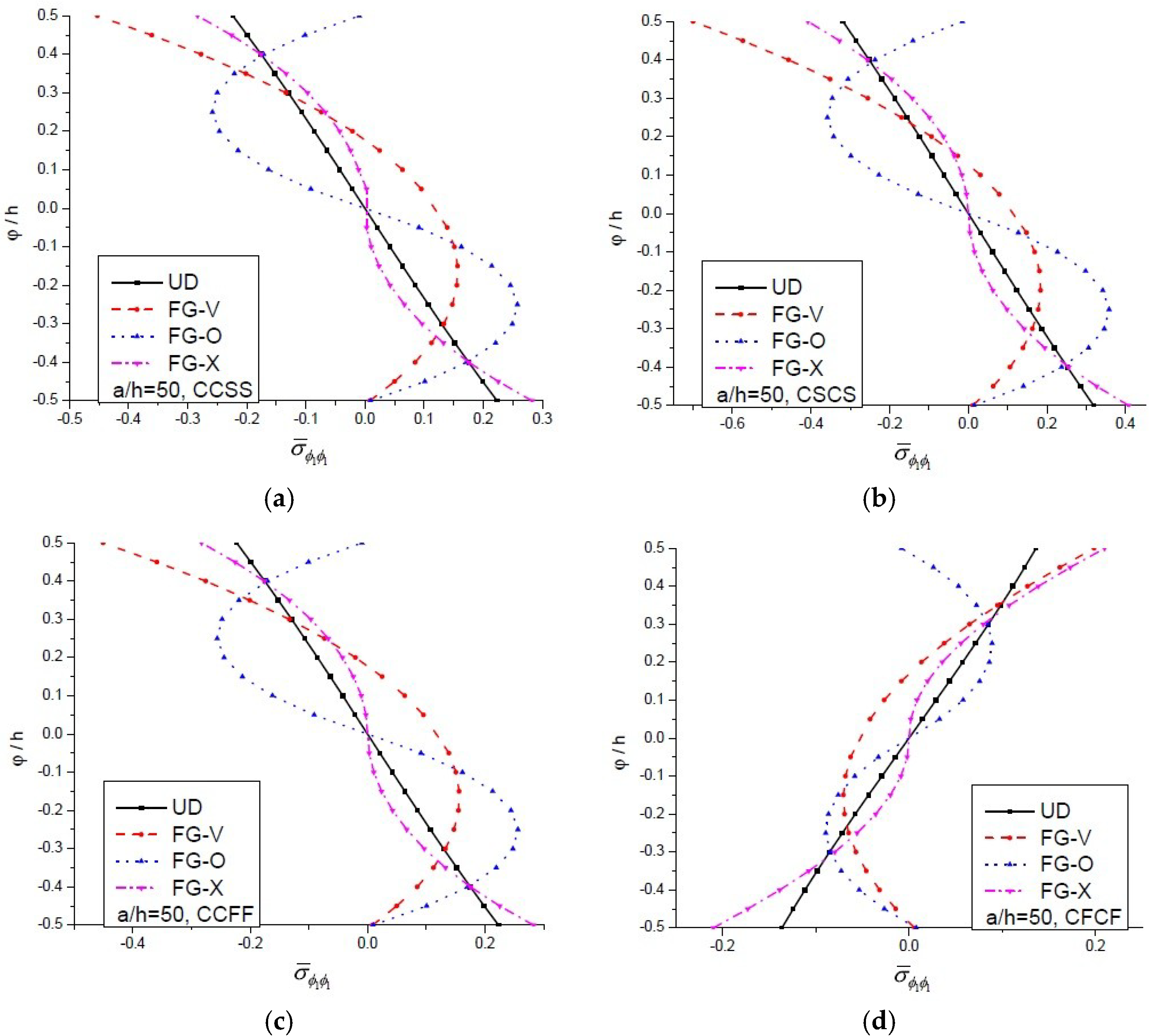
The minimum and maximum deflections were noticed for cos-cos type of loading and uniform loading, respectively. The axial stress developed in a CNT-reinforced functionally graded plate under sin-sin loading is plotted in Figure 6 against the thickness co-ordinate for CCSS, CSCS, CCFF and CFCF support conditions. The non-dimensional axial stress decreases with an increase in constraints at end support. It is interesting to note that for all types of boundary conditions, except CFCF, the nature of the graph along thickness co-ordinate is the same, for CFCF type boundary conditions, the nature of the graph is opposite to other taken boundary conditions.
6. Conclusions
In the present work, a C0 FE model based on Reddy’s TSDT was developed to investigate the flexural and free vibration behaviour of CNT-reinforced functionally graded plates. The CNT distribution through the thickness of plate is assumed to be uniform or functionally graded. The properties of CNT-reinforced plates at any point are calculated using the modified rule of mixture in which efficiency parameters are introduced into the rule of mixtures approach. The influence of the concentrated mass, volume fraction, side-to-thickness ratios, loading pattern and end support condition on the dimensionless bending and frequency parameter were also studied. Based on the present results, it can be concluded that:
- Among the considered distribution pattern of CNT, FG-X pattern results in higher dimensionless frequency parameter and lower deflection, while FG-O pattern yields lower dimensionless frequency parameters and higher dimensionless deflections.
- An increase in the dimensionless frequency parameters and decrease in the deflection of FG-CNT-reinforced plate is found when the volume fraction of CNT is increased.
- With the increase in side-to-thickness ratio, an increase in dimensionless frequency and a decrease in deflection is noticed.
- The greater constraints on boundaries results in lower values of deflection and higher values of dimensionless frequency parameters.
- The concentrated mass at the centre decreases the fundamental frequency parameter.
Author Contributions
Md Irfan Ansari and Ajay Kumar conceptualized the idea of the experiment, conducted the experiments, and analyzed the results. Md Irfan Ansari, Ajay Kumar and Stanisław Fic analyzed the results and discussed the experimental results. Danuta Barnat-Hunek provided manuscript formatting and language correction. All authors provided substantive comments.
Funding
The authors gratefully acknowledge SCIENCE & ENGINEERING RESEARCH BOARD (SERB) for the Financial Sanction of the research project FILE NO. EMR/2016/004682 and financially supported by Ministry of Science and Higher Education in Poland, within the statutory research number S/14/2018.
Conflicts of Interest
The authors declare no conflict of interest.
References
- Iijima, S. Helical microtube of graphitic carbon. Nature 1991, 354, 56–58. [Google Scholar] [CrossRef]
- Aragh, B.S.; Barati, A.H.N.; Hedayati, H. Eshelby-Mori-Tanaka approach for vibrational behavior of continuously graded carbon nanotube-reinforced cylindrical panels. Compos. Part B 2012, 43, 1943–1954. [Google Scholar] [CrossRef]
- Zhu, P.; Lei, Z.X.; Liew, K.M. Static and free vibration analyses of carbon nanotube-reinforced composite plates using finite element method with first order shear deformation plate theory. Compos. Struct. 2012, 94, 1450–1460. [Google Scholar] [CrossRef]
- Yas, M.H.; Pourasghar, A.; Kamarian, S.; Heshmati, M. Three-dimensional free vibration analysis of functionally graded nanocomposite cylindrical panels reinforced by carbon nanotube. Mater. Des. 2013, 49, 583–590. [Google Scholar] [CrossRef]
- Lei, Z.X.; Liew, K.M.; Yu, J.L. Free vibration analysis of functionally graded carbon nanotube-reinforced composite plates using the element-free kp -Ritz method in thermal environment. Compos. Struct. 2013, 106, 128–138. [Google Scholar] [CrossRef]
- Moradi-dastjerdi, R.; Foroutan, M.; Pourasghar, A.; Sotoudeh-bahreini, R. Static analysis of functionally graded carbon nanotube-reinforced composite cylinders by a mesh-free method. J. Reinf. Plast. Compos. 2013, 32, 593–601. [Google Scholar] [CrossRef]
- Zhang, L.W.; Lei, Z.X.; Liew, K.M.; Yu, J.L. Static and dynamic of carbon nanotube reinforced functionally graded cylindrical panels. Compos. Struct. 2014, 111, 205–212. [Google Scholar] [CrossRef]
- Mehrabadi, S.J.; Aragh, B.S. Thin-Walled Structures Stress analysis of functionally graded open cylindrical shell reinforced by agglomerated carbon nanotubes. Thin Walled Struct. 2014, 80, 130–141. [Google Scholar] [CrossRef]
- Budarapu, P.R.; Yb, S.S.; Javvaji, B.; Mahapatra, D.R. Vibration analysis of multi-walled carbon nanotubes embedded in elastic medium. Front. Struct. Civ. Eng. 2014, 8, 151–159. [Google Scholar] [CrossRef]
- Sankar, A.; Natarajan, S.; Ganapathi, M. Dynamic instability analysis of sandwich plates with CNT reinforced facesheets. Compos. Struct. 2016, 146, 187–200. [Google Scholar] [CrossRef]
- Nami, M.R.; Janghorban, M. Free vibration of thick functionally graded carbon nanotube-reinforced rectangular composite plates based on three-dimensional elasticity theory via differential quadrature method. Adv. Compos. Mater. 2015, 24, 439–450. [Google Scholar] [CrossRef]
- Zhang, L.W.; Cui, W.C.; Liew, K.M. Vibration analysis of functionally graded carbon nanotube reinforced composite thick plates with elastically restrained edges. Int. J. Mech. Sci. 2015, 103, 9–21. [Google Scholar] [CrossRef]
- García-macías, E.; Castro-triguero, R.; Saavedra, E.I.; Friswell, M.I.; Gallego, R. Static and free vibration analysis of functionally graded carbon nanotube reinforced skew plates. Compos. Struct. 2016, 140, 473–490. [Google Scholar] [CrossRef]
- Zhang, L.W.; Selim, B.A. Vibration analysis of CNT-reinforced thick laminated composite plates based on Reddy’s higher-order shear deformation theory. Compos. Struct. 2017, 160, 689–705. [Google Scholar] [CrossRef]
- Selim, B.A.; Zhang, L.W.; Liew, K.M. Vibration analysis of CNT reinforced functionally graded composite plates in a thermal environment based on Reddy’s higher-order shear deformation theory. Compos. Struct. 2016, 156, 276–290. [Google Scholar] [CrossRef]
- Pouresmaeeli, S.; Fazelzadeh, S.A. Frequency analysis of doubly curved functionally graded carbon nanotube-reinforced composite panels. Acta Mech. 2016, 227, 2765–2794. [Google Scholar] [CrossRef]
- Tornabene, F.; Fantuzzi, N.; Bacciocchi, M. The GDQ method for the free vibration analysis of arbitrarily shaped laminated composite shells using a NURBS-based isogeometric approach. Compos. Struct. 2016, 154, 190–218. [Google Scholar] [CrossRef]
- Fantuzzi, N.; Tornabene, F.; Bacciocchi, M.; Dimitri, R. Free vibration analysis of arbitrarily shaped Functionally Graded Carbon Nanotube-reinforced plates. Compos. Part B 2017, 115, 384–408. [Google Scholar] [CrossRef]
- Banić, D.; Bacciocchi, M.; Tornabene, F.; Ferreira, A. Influence of Winkler-Pasternak Foundation on the Vibrational Behavior of Plates and Shells Reinforced by Agglomerated Carbon Nanotubes. Appl. Sci. 2017, 7, 1228. [Google Scholar] [CrossRef]
- Mehar, K.; Panda, S.K.; Bui, T.Q.; Mahapatra, T.R. Nonlinear thermoelastic frequency analysis of functionally graded CNT-reinforced single/doubly curved shallow shell panels by FEM. J. Therm. Stresses 2017, 40, 899–916. [Google Scholar] [CrossRef]
- Huang, B.; Guo, Y.; Wang, J.; Du, J.; Qian, Z.; Ma, T.; Yi, L. Bending and free vibration analyses of antisymmetrically laminated carbon nanotube-reinforced functionally graded plates. J. Compos. Mater. 2017, 51, 3111–3125. [Google Scholar] [CrossRef]
- Asadi, H.; Souri, M.; Wang, Q. A numerical study on flow-induced instabilities of supersonic FG-CNT reinforced composite flat panels in thermal environments. Compos. Struct. 2017, 171, 113–125. [Google Scholar] [CrossRef]
- Mehar, K.; Panda, S.K. Elastic bending and stress analysis of carbon nanotube-reinforced composite plate: Experimental, numerical, and simulation. Adv. Polym. Technol. 2018, 37, 1643–1657. [Google Scholar] [CrossRef]
- Demirbas, M.D. Thermal stress analysis of functionally graded plates with temperature-dependent material properties using theory of elasticity. Compos. Part B Eng. 2017, 131, 100–124. [Google Scholar] [CrossRef]
- Tornabene, F.; Bacciocchi, M.; Fantuzzi, N.; Reddy, J.N. Multiscale Approach for Three-Phase CNT/Polymer/Fiber Laminated Nanocomposite Structures. Polym. Compos. 2017. [Google Scholar] [CrossRef]
- Liu, S.; Yu, T.; Bui, Q.T.; Xia, S. Size-dependent analysis of homogeneous and functionally graded microplates using IGA and a non-classical Kirchhoff plate theory. Compos. Struct. 2017, 172, 34–44. [Google Scholar] [CrossRef]
- Liu, S.; Yu, T.; Lich, L. Van; Yin, S.; Quoc, T. Size and surface effects on mechanical behavior of thin nanoplates incorporating microstructures using isogeometric analysis. Comput. Struct. 2019, 212, 173–187. [Google Scholar] [CrossRef]
- Alibeigloo, A.; Emtehani, A. Static and free vibration analyses of carbon nanotube- reinforced composite plate using differential quadrature method. Meccanica 2015, 50, 61–76. [Google Scholar] [CrossRef]
- Wu, C.; Li, H. Three-dimensional free vibration analysis of functionally graded carbon nanotube-reinforced composite plates with various boundary conditions. J. Vib. Control 2016, 22, 89–107. [Google Scholar] [CrossRef]
- Civalek, Ö. Free vibration of carbon nanotubes reinforced (CNTR) and functionally graded shells and plates based on FSDT via discrete singular convolution method. Compos. Part B 2017, 111, 45–49. [Google Scholar] [CrossRef]
- Duc, N.D.; Lee, J.; Nguyen-thoi, T.; Thang, P.T. Static response and free vibration of functionally graded carbon nanotube-reinforced composite rectangular plates resting on Winkler-Pasternak elastic foundations. Aerosp. Sci. Technol. 2017, 68, 391–402. [Google Scholar] [CrossRef]
- Esawi, A.M.K.; Farag, M.M. Carbon nanotube reinforced composites: Potential and current challenges. Mater. Des. 2007, 28, 2394–2401. [Google Scholar] [CrossRef]
- Fidelus, J.D.; Wiesel, E.; Gojny, F.H.; Schulte, K.; Wagner, H.D. Thermo-mechanical properties of randomly oriented carbon/epoxy nanocomposites. Compos. Part A Appl. Sci. Manuf. 2005, 36, 1555–1561. [Google Scholar] [CrossRef]
- Reddy, J.N. A simple higher-order theory for laminated composite plates. J. Appl. Mech. 1984, 51, 745–752. [Google Scholar] [CrossRef]
- Anish; Kumar, A. Ultimate Strength Analysis of Laminated Composite Sandwich Plates. Structures 2018, 14, 95–110. [Google Scholar] [CrossRef]
- Han, Y.; Elliott, J. Molecular dynamics simulations of the elastic properties of polymer/carbon nanotube composites. Comput. Mater. Sci. 2007, 39, 315–323. [Google Scholar] [CrossRef]
- Mantari, J.L.; Oktem, A.S.; Soares, C.G. Bending and free vibration analysis of isotropic and multilayered plates and shells by using a new accurate higher-order shear deformation theory. Compos. Part B 2012, 43, 3348–3360. [Google Scholar] [CrossRef]
- Srinivas, S.; Joga Rao, C.V.; Rao, A.K. An exact analysis for vibration of simply-supported homogeneous and laminated thick rectangular plates. J. Sound Vib. 1970, 12, 187–199. [Google Scholar] [CrossRef]
Figure 1.
Configuration of carbon nanotube reinforced functionally graded plates. (a) Geometry of CNT-reinforced plate; (b) UD; (c) FG-V; (d) FG-O; (e) FG-X.
Figure 1.
Configuration of carbon nanotube reinforced functionally graded plates. (a) Geometry of CNT-reinforced plate; (b) UD; (c) FG-V; (d) FG-O; (e) FG-X.

Figure 2.
The variation of dimensionless frequency parameter vs. a/h ratio for an FG-CNT-reinforced plate with different types of boundary conditions. (a) CCSS; (b) CSCS; (c) CCFF and (d) CFCF.
Figure 2.
The variation of dimensionless frequency parameter vs. a/h ratio for an FG-CNT-reinforced plate with different types of boundary conditions. (a) CCSS; (b) CSCS; (c) CCFF and (d) CFCF.

Figure 3.
The variation of dimensionless frequency parameter vs. dimensionless concentrated mass for an FG-CNT-reinforced plate for various boundary conditions.
Figure 3.
The variation of dimensionless frequency parameter vs. dimensionless concentrated mass for an FG-CNT-reinforced plate for various boundary conditions.

Figure 4.
The first four mode shape of a UD-CNT-reinforced square plate with concentrated mass at the centre for . (a) Mode 1; (b) Mode 2; (c) Mode 3 and (d) Mode 4.
Figure 4.
The first four mode shape of a UD-CNT-reinforced square plate with concentrated mass at the centre for . (a) Mode 1; (b) Mode 2; (c) Mode 3 and (d) Mode 4.

Figure 5.
The variation of transverse deflection vs. the length for an FG-CNT-reinforced plate, for (a) UD; (b) FG-V; (c) FG-O and (d) FG-X distribution subjected to sin-sin loading.
Figure 5.
The variation of transverse deflection vs. the length for an FG-CNT-reinforced plate, for (a) UD; (b) FG-V; (c) FG-O and (d) FG-X distribution subjected to sin-sin loading.

Figure 6.
The deviation of dimensionless axial stress vs. ratio for an FG-CNT-reinforced plate under sin-sin loading, for (a) CCSS; (b) CSCS; (c) CCFF and (d) CFCF boundary conditions.
Figure 6.
The deviation of dimensionless axial stress vs. ratio for an FG-CNT-reinforced plate under sin-sin loading, for (a) CCSS; (b) CSCS; (c) CCFF and (d) CFCF boundary conditions.


Table 1.
Convergence study of the present results for the dimensionless frequency parameter of a CNT-reinforced plate for clamped boundary conditions.
Table 1.
Convergence study of the present results for the dimensionless frequency parameter of a CNT-reinforced plate for clamped boundary conditions.
| Mesh Size | UD | FG-V | FG-O | FG-X |
|---|---|---|---|---|
| 8 × 8 | 18.2872 | 17.7565 | 16.0741 | 18.9550 |
| 10 × 10 | 18.2860 | 17.7554 | 16.0728 | 18.9538 |
| 12 × 12 | 18.2848 | 17.7542 | 16.0719 | 18.9531 |
| 14 × 14 | 18.2843 | 17.7536 | 16.0714 | 18.9526 |
| 16 × 16 | 18.2842 | 17.7534 | 16.0716 | 18.9525 |
Table 2.
Convergence study of the present results for the deflection of a CNT-reinforced plate for clamped boundary conditions.
Table 2.
Convergence study of the present results for the deflection of a CNT-reinforced plate for clamped boundary conditions.
| Mesh Size | UD | FG-V | FG-O | FG-X |
|---|---|---|---|---|
| 8 × 8 | 0.00904 | 0.00926 | 0.01061 | 0.00867 |
| 10 × 10 | 0.00892 | 0.00918 | 0.01049 | 0.00856 |
| 12 × 12 | 0.00884 | 0.00914 | 0.01044 | 0.00851 |
| 14 × 14 | 0.00881 | 0.00912 | 0.01041 | 0.00848 |
| 16 × 16 | 0.00880 | 0.00912 | 0.01040 | 0.00848 |
Table 3.
Dimensional frequency parameter of the simply supported square isotropic plate.
| Reference | Mode | ||
|---|---|---|---|
| (1,1) | (1,2) | (1,3) | |
| Present | 0.093 | 0.221 | 0.415 |
| Mantari et al. [37] | 0.093 | 0.222 | 0.415 |
| Srinivas et al. [38] | 0.093 | 0.223 | 0.417 |
Table 4.
Dimensionless first six natural frequencies for a UD CNT-reinforced square plate with a/h ratios.
Table 4.
Dimensionless first six natural frequencies for a UD CNT-reinforced square plate with a/h ratios.
| Mode | a/h = 10 | a/h = 20 | a/h = 50 | ||||
|---|---|---|---|---|---|---|---|
| Ref. [3] | Present | Ref. [3] | Present | Ref. [3] | Present | ||
| 0.11 | 1 | 17.625 | 18.284 | 28.400 | 29.232 | 39.730 | 41.246 |
| 2 | 23.041 | 23.793 | 33.114 | 34.108 | 43.876 | 45.501 | |
| 3 | 33.592 | 34.188 | 44.559 | 45.456 | 54.768 | 56.313 | |
| 4 | 33.729 | 35.188 | 59.198 | 60.708 | 74.488 | 75.080 | |
| 5 | 37.011 | 38.536 | 61.851 | 63.003 | 98.291 | 100.577 | |
| 6 | 37.317 | 38.738 | 63.043 | 63.553 | 100.537 | 101.437 | |
| 0.14 | 1 | 18.127 | 18.854 | 29.911 | 30.795 | 43.583 | 45.216 |
| 2 | 23.572 | 24.374 | 34.516 | 35.558 | 47.479 | 49.218 | |
| 3 | 34.252 | 34.874 | 45.898 | 46.830 | 57.968 | 59.617 | |
| 4 | 34.650 | 36.267 | 61.628 | 63.337 | 77.395 | 78.064 | |
| 5 | 37.921 | 39.384 | 64.199 | 64.457 | 106.371 | 104.359 | |
| 6 | 37.972 | 39.592 | 64.496 | 66.100 | 106.487 | 108.807 | |
| 0.17 | 1 | 22.011 | 22.795 | 35.316 | 36.286 | 49.074 | 50.802 |
| 2 | 28.801 | 29.679 | 41.253 | 42.400 | 54.324 | 56.170 | |
| 3 | 42.015 | 42.666 | 55.267 | 56.600 | 68.069 | 69.766 | |
| 4 | 42.132 | 43.878 | 73.769 | 75.518 | 92.868 | 93.286 | |
| 5 | 46.250 | 48.066 | 77.109 | 78.531 | 121.669 | 124.191 | |
| 6 | 46.694 | 48.343 | 78.801 | 79.084 | 124.518 | 126.244 | |
Table 5.
Dimensionless first six natural frequencies for an FG-V CNT-reinforced square plate with a/h ratios.
Table 5.
Dimensionless first six natural frequencies for an FG-V CNT-reinforced square plate with a/h ratios.
| Mode | a/h = 10 | a/h = 20 | a/h = 50 | ||||
|---|---|---|---|---|---|---|---|
| Ref. [3] | Present | Ref. [3] | Present | Ref. [3] | Present | ||
| 0.11 | 1 | 17.211 | 17.753 | 26.304 | 26.693 | 34.165 | 34.480 |
| 2 | 22.812 | 23.462 | 31.496 | 32.099 | 39.043 | 39.584 | |
| 3 | 33.070 | 34.035 | 43.589 | 44.133 | 51.204 | 51.815 | |
| 4 | 33.552 | 34.355 | 56.249 | 57.061 | 72.202 | 71.954 | |
| 5 | 36.528 | 37.889 | 59.249 | 60.253 | 86.291 | 86.133 | |
| 6 | 37.437 | 38.841 | 62.608 | 62.218 | 89.054 | 89.105 | |
| 0.14 | 1 | 17.791 | 18.405 | 27.926 | 28.371 | 37.568 | 37.909 |
| 2 | 23.413 | 24.113 | 32.976 | 33.629 | 42.175 | 42.733 | |
| 3 | 34.101 | 34.792 | 44.989 | 45.573 | 53.963 | 54.590 | |
| 4 | 34.275 | 35.553 | 58.951 | 59.968 | 74.785 | 74.546 | |
| 5 | 37.538 | 39.053 | 61.816 | 63.051 | 94.022 | 93.911 | |
| 6 | 38.159 | 39.574 | 64.135 | 63.758 | 96.573 | 96.680 | |
| 0.17 | 1 | 21.544 | 22.152 | 32.686 | 33.050 | 42.078 | 42.292 |
| 2 | 28.613 | 29.332 | 39.279 | 39.895 | 48.309 | 48.796 | |
| 3 | 41.431 | 42.605 | 54.560 | 55.058 | 63.755 | 64.286 | |
| 4 | 42.119 | 42.912 | 70.149 | 70.903 | 90.293 | 89.657 | |
| 5 | 45.796 | 47.364 | 73.926 | 74.948 | 106.513 | 105.881 | |
| 6 | 47.055 | 48.721 | 78.522 | 77.777 | 110.055 | 109.679 | |
Table 6.
Maximum transverse deflection for a UD CNT-reinforced square plate with a/h ratios.
| BC | a/h = 10 | a/h = 20 | a/h = 50 | ||||
|---|---|---|---|---|---|---|---|
| Ref. [3] | Present | Ref. [3] | Present | Ref. [3] | Present | ||
| CCCC | 0.11 | 0.00222 | 0.00207 | 0.01339 | 0.01257 | 0.2618 | 0.24056 |
| 0.14 | 0.00208 | 0.00192 | 0.01188 | 0.01115 | 0.2131 | 0.19644 | |
| 0.17 | 0.00141 | 0.00131 | 0.00856 | 0.00806 | 0.1698 | 0.15695 | |
| SSSS | 0.11 | 0.00373 | 0.00354 | 0.03628 | 0.03352 | 1.1550 | 1.04729 |
| 0.14 | 0.00330 | 0.00314 | 0.03001 | 0.02779 | 0.9175 | 0.83205 | |
| 0.17 | 0.00239 | 0.00227 | 0.02348 | 0.02180 | 0.7515 | 0.68655 | |
| SCSC | 0.11 | 0.00332 | 0.00313 | 0.03393 | 0.03127 | 1.0990 | 0.99624 |
| 0.14 | 0.00297 | 0.00281 | 0.02852 | 0.02634 | 0.8890 | 0.80555 | |
| 0.17 | 0.00212 | 0.00201 | 0.02190 | 0.02028 | 0.7135 | 0.65105 | |
| SFSF | 0.11 | 0.00344 | 0.00339 | 0.03341 | 0.03223 | 1.0680 | 1.01428 |
| 0.14 | 0.00302 | 0.00297 | 0.02760 | 0.02654 | 0.8505 | 0.80295 | |
| 0.17 | 0.00207 | 0.00218 | 0.02162 | 0.02096 | 0.6950 | 0.66441 | |
Table 7.
Dimensionless first six natural frequencies for FG-CNT-reinforced plate with several types of boundary conditions .
Table 7.
Dimensionless first six natural frequencies for FG-CNT-reinforced plate with several types of boundary conditions .
| CNT Distribution | Mode | SSSS | CCCC | CCSS | CSCS | CCFF | CFCF |
|---|---|---|---|---|---|---|---|
| UD CNT | 1 | 13.8852 | 18.2842 | 17.3753 | 15.8868 | 17.0425 | 5.8250 |
| 2 | 18.1994 | 23.7934 | 19.4223 | 20.8718 | 17.1008 | 8.9023 | |
| 3 | 19.4225 | 34.1882 | 20.6985 | 25.6174 | 18.5180 | 18.0312 | |
| 4 | 19.4275 | 35.1886 | 29.5574 | 31.1128 | 19.2125 | 19.2182 | |
| 5 | 28.1212 | 38.5362 | 34.7213 | 34.2514 | 24.5644 | 20.8003 | |
| 6 | 33.2913 | 38.7388 | 36.7252 | 36.978 | 34.4553 | 22.4299 | |
| FG-V CNT | 1 | 12.6013 | 17.7534 | 16.8089 | 15.0616 | 16.4289 | 5.0825 |
| 2 | 17.4092 | 23.4625 | 19.4794 | 20.3638 | 16.5145 | 8.5314 | |
| 3 | 19.4794 | 34.0359 | 20.3062 | 25.6864 | 18.0592 | 17.9081 | |
| 4 | 19.4848 | 34.3556 | 29.3712 | 30.8794 | 19.2392 | 19.1983 | |
| 5 | 27.7626 | 37.8893 | 33.8705 | 33.1631 | 24.3163 | 19.4767 | |
| 6 | 31.9032 | 38.8412 | 36.0454 | 36.1119 | 33.5464 | 21.3183 | |
| FG-O CNT | 1 | 10.9949 | 16.0716 | 15.0774 | 13.4469 | 14.6154 | 4.3402 |
| 2 | 16.1348 | 22.0695 | 18.8182 | 19.0449 | 14.7550 | 7.9636 | |
| 3 | 19.3738 | 31.0727 | 19.3738 | 25.5485 | 16.5016 | 17.0273 | |
| 4 | 19.3788 | 32.8351 | 28.0759 | 29.7007 | 19.1524 | 17.3247 | |
| 5 | 26.6463 | 34.9777 | 30.5620 | 29.7414 | 22.9926 | 19.1600 | |
| 6 | 28.2949 | 38.6394 | 33.0506 | 33.0550 | 30.1205 | 19.2511 | |
| FG-X CNT | 1 | 15.1552 | 18.9525 | 18.0228 | 16.7777 | 17.7014 | 6.6028 |
| 2 | 19.3040 | 24.5186 | 19.5714 | 21.7384 | 17.7463 | 9.5252 | |
| 3 | 19.5714 | 35.0117 | 21.3967 | 25.8180 | 19.1656 | 18.7035 | |
| 4 | 19.5764 | 36.3490 | 30.4141 | 32.0371 | 19.3693 | 19.3737 | |
| 5 | 29.1832 | 39.0379 | 35.8724 | 35.5379 | 25.3411 | 22.2820 | |
| 6 | 34.7403 | 39.6836 | 37.8550 | 38.2271 | 35.6335 | 23.7887 |
Table 8.
The dimensionless first six natural frequencies for FG-CNT-reinforced plate with several types of boundary conditions .
Table 8.
The dimensionless first six natural frequencies for FG-CNT-reinforced plate with several types of boundary conditions .
| CNT Distribution | Mode | SSSS | CCCC | CCSS | CSCS | CCFF | CFCF |
|---|---|---|---|---|---|---|---|
| UD CNT | 1 | 14.6682 | 18.8542 | 17.9441 | 16.5233 | 17.6226 | 6.2616 |
| 2 | 18.8705 | 24.3743 | 19.7690 | 21.4698 | 17.6727 | 9.2459 | |
| 3 | 19.7693 | 34.8746 | 21.2538 | 26.0654 | 19.0664 | 18.4145 | |
| 4 | 19.7746 | 36.2671 | 30.1760 | 31.7742 | 19.5794 | 19.5556 | |
| 5 | 28.7844 | 39.3845 | 35.8002 | 35.3843 | 25.1267 | 21.7948 | |
| 6 | 34.4929 | 39.5926 | 37.7684 | 38.0703 | 35.5519 | 23.3518 | |
| FG-V CNT | 1 | 13.4159 | 18.4059 | 17.4633 | 15.7609 | 17.1005 | 5.4974 |
| 2 | 18.0906 | 24.1135 | 19.8706 | 21.0094 | 17.1744 | 8.8533 | |
| 3 | 19.8712 | 34.7921 | 20.9318 | 26.1926 | 18.6808 | 18.3042 | |
| 4 | 19.8761 | 35.5532 | 30.0544 | 31.5929 | 19.6521 | 19.6276 | |
| 5 | 28.4493 | 39.0533 | 35.0697 | 34.4452 | 24.9393 | 20.4615 | |
| 6 | 33.2846 | 39.5746 | 37.1960 | 37.3341 | 34.7677 | 22.2670 | |
| FG-O CNT | 1 | 11.7336 | 16.7149 | 15.7447 | 14.1157 | 15.3166 | 4.7012 |
| 2 | 16.6636 | 22.6163 | 19.3724 | 19.5683 | 15.4370 | 8.1901 | |
| 3 | 19.7233 | 32.2978 | 19.7233 | 26.0009 | 17.0947 | 17.4986 | |
| 4 | 19.7283 | 33.3984 | 28.5693 | 30.2258 | 19.5228 | 18.0877 | |
| 5 | 27.0960 | 36.0888 | 31.7979 | 31.0146 | 23.4731 | 19.5010 | |
| 6 | 29.6777 | 39.2902 | 34.1720 | 34.2161 | 31.3969 | 20.1111 | |
| FG-X CNT | 1 | 15.8603 | 19.4936 | 18.5402 | 17.3716 | 18.2150 | 7.0295 |
| 2 | 19.9936 | 25.1816 | 19.9936 | 22.4091 | 18.2580 | 9.9358 | |
| 3 | 19.9987 | 35.8970 | 21.9948 | 26.3643 | 19.7081 | 19.2714 | |
| 4 | 20.0198 | 37.3880 | 31.2273 | 32.9064 | 19.8096 | 19.7841 | |
| 5 | 30.0505 | 39.8323 | 36.8998 | 36.5737 | 26.0403 | 23.2464 | |
| 6 | 35.7881 | 40.7784 | 38.9121 | 39.3039 | 36.6646 | 24.7286 |
Table 9.
The dimensionless first six natural frequencies for FG-CNT-reinforced plate with several types of boundary conditions .
Table 9.
The dimensionless first six natural frequencies for FG-CNT-reinforced plate with several types of boundary conditions .
| CNT Distribution | Mode | SSSS | CCCC | CCSS | CSCS | CCFF | CFCF |
|---|---|---|---|---|---|---|---|
| UD CNT | 1 | 17.2282 | 22.7953 | 21.6602 | 19.7729 | 21.2427 | 7.2029 |
| 2 | 22.6414 | 29.6791 | 24.3013 | 26.0099 | 21.3182 | 11.0742 | |
| 3 | 24.3016 | 42.6665 | 25.8122 | 32.0048 | 23.0929 | 22.4866 | |
| 4 | 24.3082 | 43.8786 | 36.8752 | 38.8103 | 24.0325 | 23.9779 | |
| 5 | 35.0543 | 48.0664 | 43.2954 | 42.6982 | 30.6427 | 25.8591 | |
| 6 | 41.4851 | 48.3439 | 45.8044 | 46.1123 | 42.9599 | 27.9148 | |
| FG-V CNT | 1 | 15.5951 | 22.1523 | 20.9643 | 18.7382 | 20.4814 | 6.2639 |
| 2 | 21.6792 | 29.3329 | 24.5003 | 25.4208 | 20.5947 | 10.6346 | |
| 3 | 24.5009 | 42.6051 | 25.3672 | 32.2575 | 22.5474 | 22.4044 | |
| 4 | 24.5077 | 42.9122 | 36.7474 | 38.6306 | 24.1940 | 24.0052 | |
| 5 | 34.7015 | 47.3646 | 42.3047 | 41.3726 | 30.4090 | 24.2769 | |
| 6 | 39.7413 | 48.7211 | 45.0484 | 45.0965 | 41.8897 | 26.5494 | |
| FG-O CNT | 1 | 13.5986 | 20.0823 | 18.8814 | 16.7451 | 18.3266 | 5.3426 |
| 2 | 19.8862 | 27.4023 | 23.4006 | 23.5759 | 18.4958 | 9.7936 | |
| 3 | 24.2623 | 38.9769 | 24.2623 | 31.9471 | 20.5956 | 21.1536 | |
| 4 | 24.2685 | 40.6865 | 34.7258 | 36.7391 | 23.9782 | 21.4110 | |
| 5 | 32.8334 | 43.7158 | 38.3598 | 37.2540 | 28.4740 | 23.9263 | |
| 6 | 35.4341 | 48.2629 | 41.3522 | 41.2969 | 37.8326 | 23.9562 | |
| FG-X CNT | 1 | 18.7939 | 23.6698 | 22.4562 | 20.8923 | 22.0245 | 8.1719 |
| 2 | 24.2372 | 30.8645 | 24.6906 | 27.3472 | 22.0930 | 12.0063 | |
| 3 | 24.6906 | 44.2396 | 26.8771 | 32.5214 | 23.9830 | 23.7798 | |
| 4 | 24.6969 | 45.3645 | 38.4825 | 40.5259 | 24.4268 | 24.3702 | |
| 5 | 36.9439 | 49.1202 | 44.7435 | 44.2607 | 32.0150 | 27.6660 | |
| 6 | 43.1742 | 49.7057 | 47.3649 | 47.7933 | 44.4161 | 29.6741 |
Table 10.
Dimensionless first six natural frequencies for an FG-CNT-reinforced plate with simply supported boundary conditions and concentrated mass at the centre .
Table 10.
Dimensionless first six natural frequencies for an FG-CNT-reinforced plate with simply supported boundary conditions and concentrated mass at the centre .
| CNT Distribution | First Six Minimum Frequencies | ||||||
|---|---|---|---|---|---|---|---|
| 1 | 2 | 3 | 4 | 5 | 6 | ||
| UD CNT | 0 | 13.8852 | 18.1994 | 19.4225 | 19.4275 | 28.1212 | 33.2913 |
| 0.5 | 6.3132 | 18.1999 | 18.8956 | 19.4223 | 19.4272 | 32.0719 | |
| 1 | 4.5988 | 18.1999 | 18.4937 | 19.4223 | 19.4272 | 31.8782 | |
| 2 | 3.2991 | 18.1999 | 18.3010 | 19.4223 | 19.4272 | 31.7861 | |
| 0 | 12.6013 | 17.4092 | 19.4794 | 19.4848 | 27.7626 | 31.9032 | |
| FG-V CNT | 0.5 | 5.9584 | 17.4093 | 18.1022 | 19.4794 | 19.4844 | 31.7275 |
| 1 | 4.3636 | 17.4093 | 17.6274 | 19.4794 | 19.4844 | 31.5303 | |
| 2 | 3.1390 | 17.3983 | 17.4093 | 19.4794 | 19.4844 | 31.4366 | |
| 0 | 10.9949 | 16.1348 | 19.3738 | 19.3788 | 26.6463 | 28.2949 | |
| FG-O CNT | 0.5 | 5.3902 | 16.1348 | 16.8670 | 19.3738 | 19.3788 | 28.2949 |
| 1 | 3.9718 | 16.1348 | 16.3302 | 19.3738 | 19.3788 | 28.2949 | |
| 2 | 2.8665 | 16.0686 | 16.1348 | 19.3738 | 19.3788 | 28.2949 | |
| 0 | 15.1552 | 19.304 | 19.5714 | 19.5764 | 29.1832 | 34.7403 | |
| FG-X CNT | 0.5 | 6.6718 | 19.3040 | 19.5714 | 19.5764 | 19.8985 | 33.0660 |
| 1 | 4.8415 | 19.3040 | 19.5383 | 19.5714 | 19.5764 | 32.8820 | |
| 2 | 3.4667 | 19.3040 | 19.3664 | 19.5714 | 19.5764 | 32.7943 | |
Table 11.
Central transverse deflection of an FG-CNT-reinforced square plate subjected to sin-sin loading .
Table 11.
Central transverse deflection of an FG-CNT-reinforced square plate subjected to sin-sin loading .
| CNT Distribution | a/h | SSSS | CCCC | CCSS | CSCS | CCFF | CFCF |
|---|---|---|---|---|---|---|---|
| UD CNT | 5 | 0.01216 | 0.00880 | 0.01008 | 0.01040 | 0.01008 | 0.03264 |
| 10 | 0.00502 | 0.00315 | 0.00328 | 0.00397 | 0.00323 | 0.01749 | |
| 20 | 0.00300 | 0.00126 | 0.00125 | 0.00182 | 0.00124 | 0.01361 | |
| 50 | 0.00241 | 0.00064 | 0.00064 | 0.00115 | 0.00064 | 0.01245 | |
| 100 | 0.00232 | 0.00055 | 0.00055 | 0.00105 | 0.00055 | 0.01228 | |
| FG-V CNT | 5 | 0.01216 | 0.00912 | 0.01040 | 0.01072 | 0.01008 | 0.03872 |
| 10 | 0.00525 | 0.00336 | 0.00353 | 0.00426 | 0.00349 | 0.02270 | |
| 20 | 0.00326 | 0.00153 | 0.00153 | 0.00223 | 0.00152 | 0.01887 | |
| 50 | 0.00267 | 0.00094 | 0.00093 | 0.00159 | 0.00093 | 0.01776 | |
| 100 | 0.00259 | 0.00085 | 0.00084 | 0.00150 | 0.00084 | 0.01759 | |
| FG-O CNT | 5 | 0.01584 | 0.01040 | 0.01216 | 0.01280 | 0.01216 | 0.05216 |
| 10 | 0.00800 | 0.00416 | 0.00443 | 0.00559 | 0.00435 | 0.03142 | |
| 20 | 0.00584 | 0.00204 | 0.00207 | 0.00320 | 0.00204 | 0.02670 | |
| 50 | 0.00520 | 0.00136 | 0.00135 | 0.00245 | 0.00135 | 0.02536 | |
| 100 | 0.00511 | 0.00125 | 0.00125 | 0.00234 | 0.00124 | 0.02516 | |
| FG-X CNT | 5 | 0.01104 | 0.00848 | 0.00976 | 0.00976 | 0.00976 | 0.02816 |
| 10 | 0.00420 | 0.00292 | 0.00302 | 0.00353 | 0.00298 | 0.01373 | |
| 20 | 0.00219 | 0.00105 | 0.00105 | 0.00145 | 0.00105 | 0.00981 | |
| 50 | 0.00160 | 0.00045 | 0.00045 | 0.00078 | 0.00045 | 0.00860 | |
| 100 | 0.00151 | 0.00036 | 0.00036 | 0.00068 | 0.00036 | 0.00842 |
Table 12.
Central transverse deflection of an FG-CNT-reinforced square plate subjected to sin-sin loading .
Table 12.
Central transverse deflection of an FG-CNT-reinforced square plate subjected to sin-sin loading .
| CNT Distribution | a/h | SSSS | CCCC | CCSS | CSCS | CCFF | CFCF |
|---|---|---|---|---|---|---|---|
| UD CNT | 5 | 0.01136 | 0.00848 | 0.00976 | 0.01008 | 0.00944 | 0.02960 |
| 10 | 0.00447 | 0.00294 | 0.00305 | 0.00363 | 0.00300 | 0.01518 | |
| 20 | 0.00251 | 0.00112 | 0.00111 | 0.00159 | 0.00111 | 0.01140 | |
| 50 | 0.00194 | 0.00053 | 0.00053 | 0.00093 | 0.00052 | 0.01026 | |
| 100 | 0.00186 | 0.00044 | 0.00044 | 0.00084 | 0.00044 | 0.01009 | |
| FG-V CNT | 5 | 0.01136 | 0.00848 | 0.00976 | 0.01008 | 0.00976 | 0.03392 |
| 10 | 0.00464 | 0.00311 | 0.00326 | 0.00386 | 0.00319 | 0.01936 | |
| 20 | 0.00272 | 0.00134 | 0.00134 | 0.00191 | 0.00133 | 0.01570 | |
| 50 | 0.00216 | 0.00076 | 0.00076 | 0.00129 | 0.00076 | 0.01463 | |
| 100 | 0.00207 | 0.00068 | 0.00067 | 0.00120 | 0.00067 | 0.01447 | |
| FG-O CNT | 5 | 0.01440 | 0.00976 | 0.01136 | 0.01216 | 0.01136 | 0.04544 |
| 10 | 0.00699 | 0.00380 | 0.00403 | 0.00502 | 0.00395 | 0.02640 | |
| 20 | 0.00487 | 0.00177 | 0.00178 | 0.00273 | 0.00176 | 0.02208 | |
| 50 | 0.00071 | 0.00111 | 0.00110 | 0.00200 | 0.00110 | 0.02084 | |
| 100 | 0.00417 | 0.00101 | 0.00100 | 0.00190 | 0.00100 | 0.02065 | |
| FG-X CNT | 5 | 0.01040 | 0.00800 | 0.00944 | 0.00944 | 0.00912 | 0.02592 |
| 10 | 0.00382 | 0.00273 | 0.00284 | 0.00328 | 0.00279 | 0.01210 | |
| 20 | 0.00186 | 0.00096 | 0.00095 | 0.00129 | 0.00095 | 0.00824 | |
| 50 | 0.00128 | 0.00038 | 0.00037 | 0.00064 | 0.00037 | 0.00705 | |
| 100 | 0.00120 | 0.00029 | 0.00029 | 0.00054 | 0.00029 | 0.00686 |
Table 13.
Central transverse deflection of an FG-CNT-reinforced square plate subjected to sin-sin loading .
Table 13.
Central transverse deflection of an FG-CNT-reinforced square plate subjected to sin-sin loading .
| CNT Distribution | a/h | SSSS | CCCC | CCSS | CSCS | CCFF | CFCF |
|---|---|---|---|---|---|---|---|
| UD CNT | 5 | 0.00768 | 0.00576 | 0.00640 | 0.00672 | 0.00640 | 0.02080 |
| 10 | 0.00321 | 0.00200 | 0.00208 | 0.00252 | 0.00206 | 0.01130 | |
| 20 | 0.00195 | 0.00080 | 0.00080 | 0.00118 | 0.00080 | 0.00884 | |
| 50 | 0.00158 | 0.00042 | 0.00042 | 0.00075 | 0.00042 | 0.00811 | |
| 100 | 0.00152 | 0.00036 | 0.00036 | 0.00069 | 0.00036 | 0.00800 | |
| FG-V CNT | 5 | 0.00768 | 0.00576 | 0.00640 | 0.00672 | 0.00640 | 0.02480 |
| 10 | 0.00336 | 0.00214 | 0.00225 | 0.00271 | 0.00221 | 0.01476 | |
| 20 | 0.00212 | 0.00098 | 0.00099 | 0.00144 | 0.00098 | 0.01235 | |
| 50 | 0.00175 | 0.00061 | 0.00061 | 0.00105 | 0.00061 | 0.01165 | |
| 100 | 0.00170 | 0.00056 | 0.00056 | 0.00099 | 0.00055 | 0.01154 | |
| FG-O CNT | 5 | 0.01008 | 0.00672 | 0.00768 | 0.00800 | 0.00768 | 0.03328 |
| 10 | 0.00517 | 0.00263 | 0.00279 | 0.00355 | 0.00275 | 0.02054 | |
| 20 | 0.00384 | 0.00132 | 0.00133 | 0.00208 | 0.00132 | 0.01763 | |
| 50 | 0.00345 | 0.00089 | 0.00089 | 0.00162 | 0.00089 | 0.01681 | |
| 100 | 0.00339 | 0.00083 | 0.00083 | 0.00155 | 0.00082 | 0.01669 | |
| FG-X CNT | 5 | 0.00704 | 0.00544 | 0.00608 | 0.00640 | 0.00608 | 0.01808 |
| 10 | 0.00269 | 0.00185 | 0.00193 | 0.00225 | 0.00191 | 0.00876 | |
| 20 | 0.00142 | 0.00068 | 0.00067 | 0.00094 | 0.00067 | 0.00628 | |
| 50 | 0.00104 | 0.00029 | 0.00029 | 0.00051 | 0.00029 | 0.00553 | |
| 100 | 0.00098 | 0.00024 | 0.00023 | 0.00045 | 0.00023 | 0.00541 |
© 2018 by the authors. Licensee MDPI, Basel, Switzerland. This article is an open access article distributed under the terms and conditions of the Creative Commons Attribution (CC BY) license (http://creativecommons.org/licenses/by/4.0/).
Share and Cite
MDPI and ACS Style
Ansari, M.I.; Kumar, A.; Fic, S.; Barnat-Hunek, D. Flexural and Free Vibration Analysis of CNT-Reinforced Functionally Graded Plate. Materials 2018, 11, 2387. https://doi.org/10.3390/ma11122387
AMA Style
Ansari MI, Kumar A, Fic S, Barnat-Hunek D. Flexural and Free Vibration Analysis of CNT-Reinforced Functionally Graded Plate. Materials. 2018; 11(12):2387. https://doi.org/10.3390/ma11122387
Chicago/Turabian StyleAnsari, Md Irfan, Ajay Kumar, Stanisław Fic, and Danuta Barnat-Hunek. 2018. "Flexural and Free Vibration Analysis of CNT-Reinforced Functionally Graded Plate" Materials 11, no. 12: 2387. https://doi.org/10.3390/ma11122387
Note that from the first issue of 2016, this journal uses article numbers instead of page numbers. See further details here.