Closed Die Upsetting of Aluminum Matrix Composites Reinforced with Molybdenum Disulfide Nanocrystals and Multilayer Graphene, Implemented using the SPS Process—Microstructure Evolution


Abstract
:1. Introduction
2. Materials and Methods
3. Results and Discussion
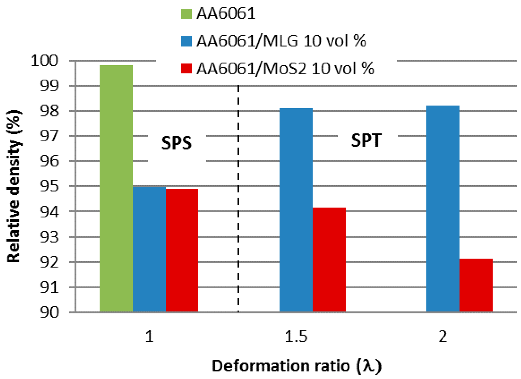
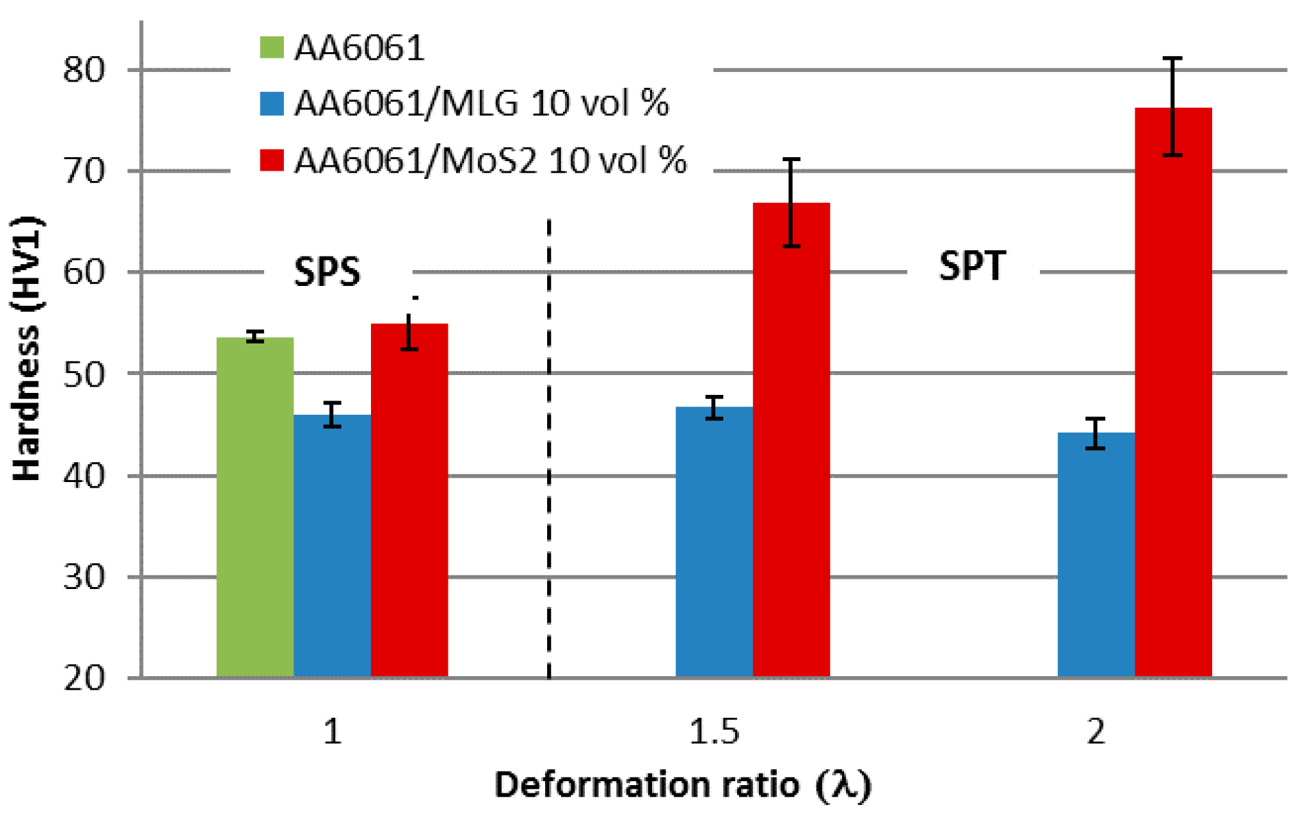
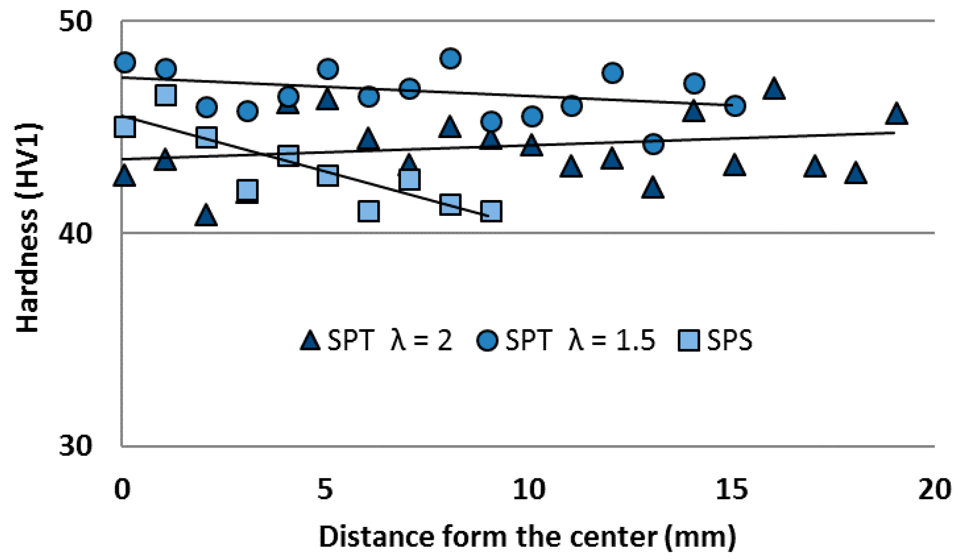
3.1. Physical Properties
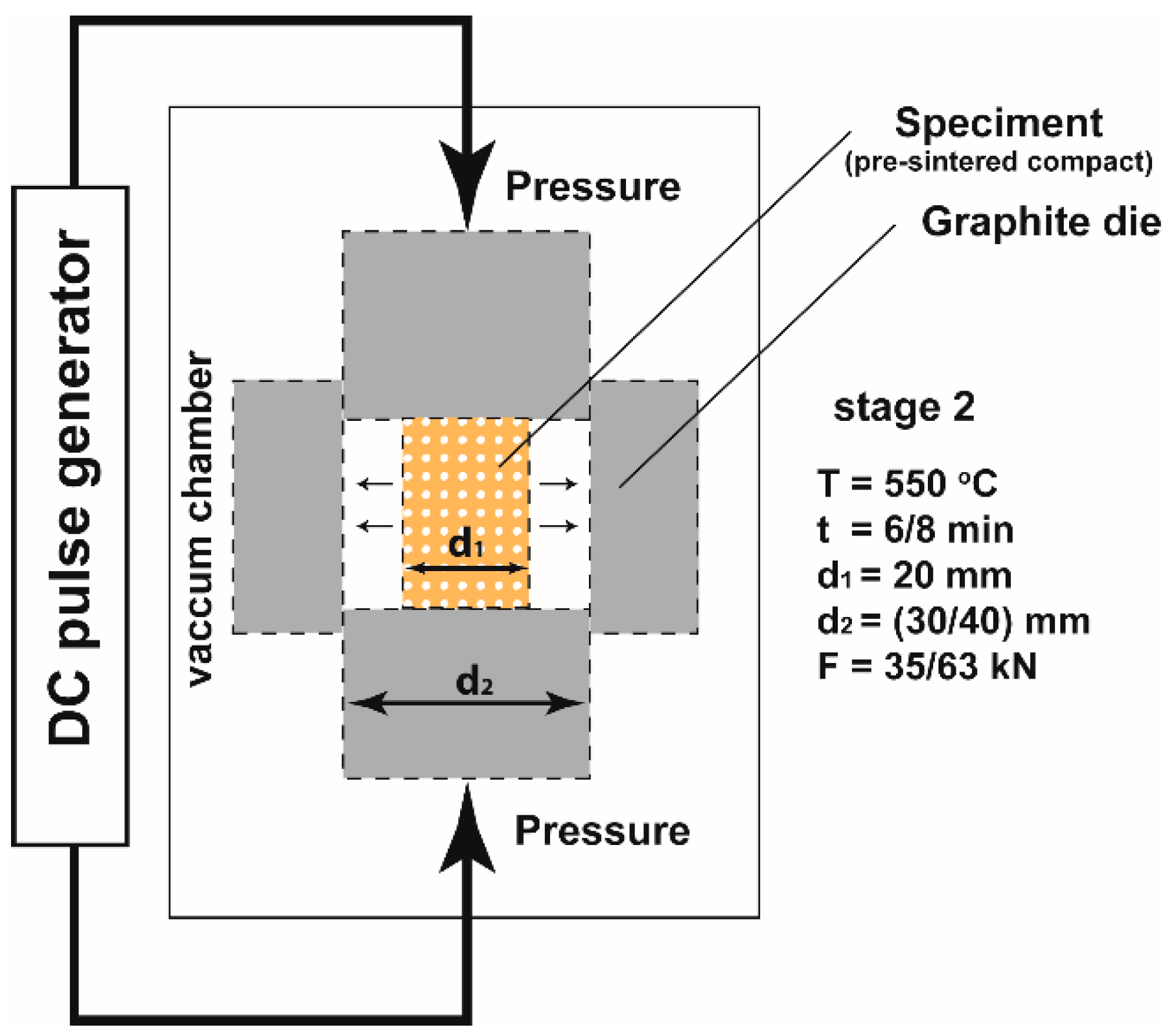
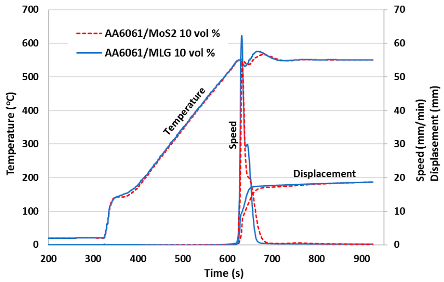
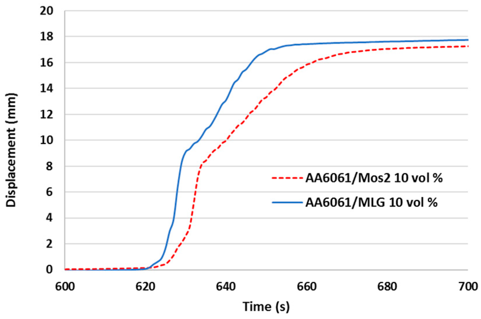
3.2. Processing
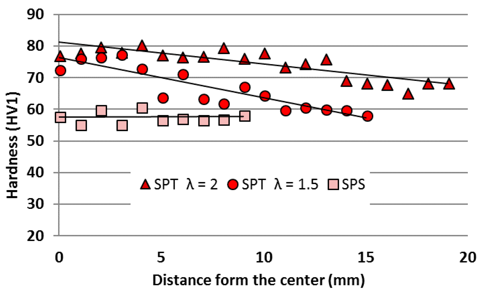
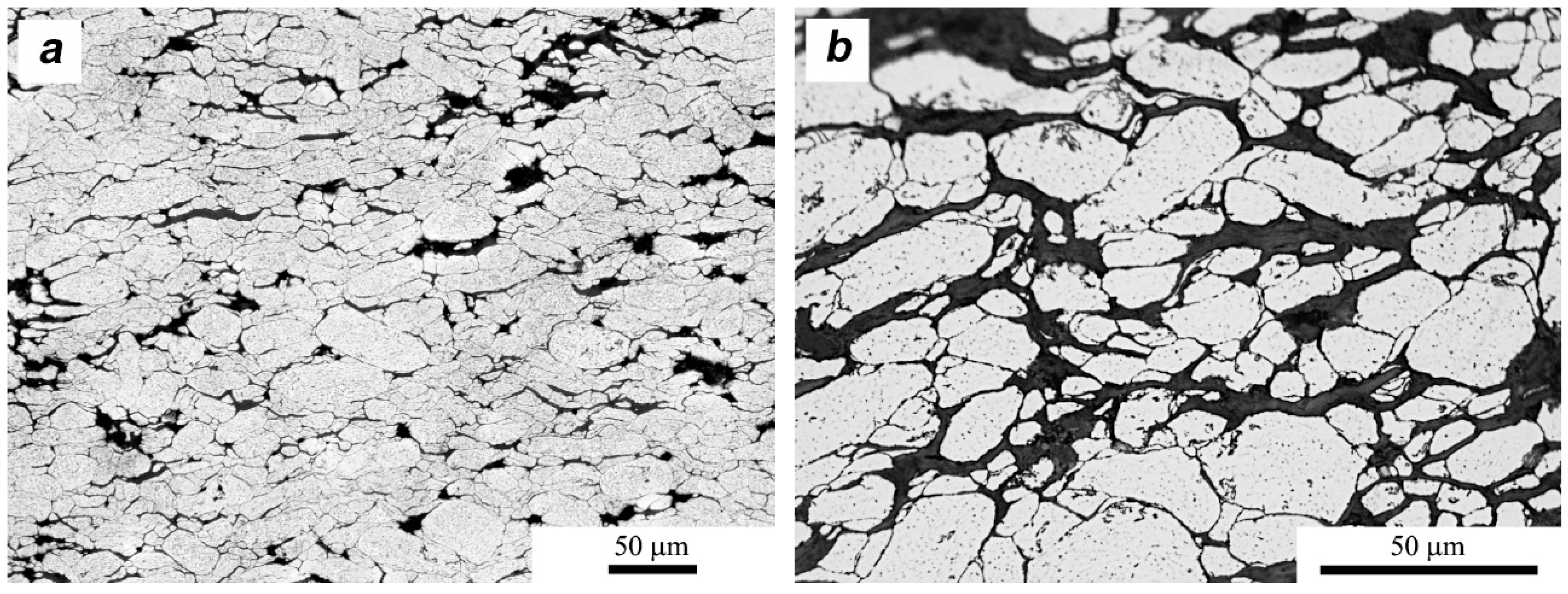
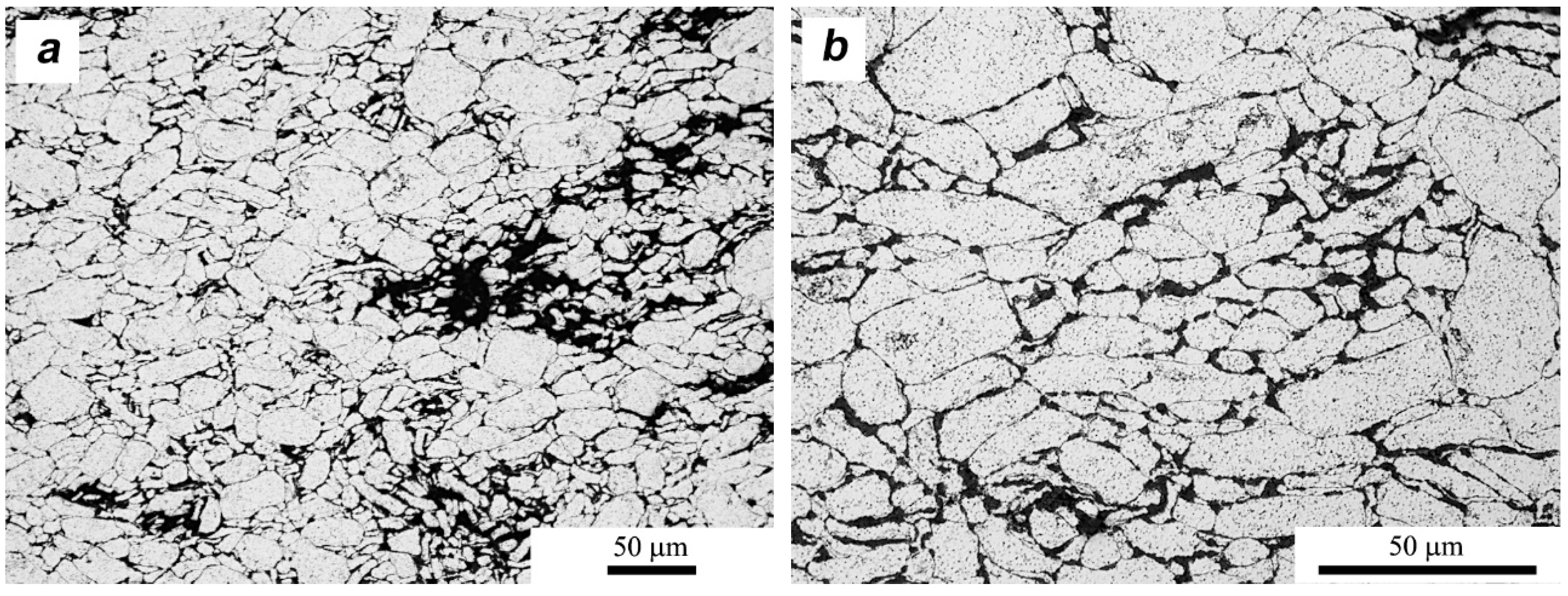
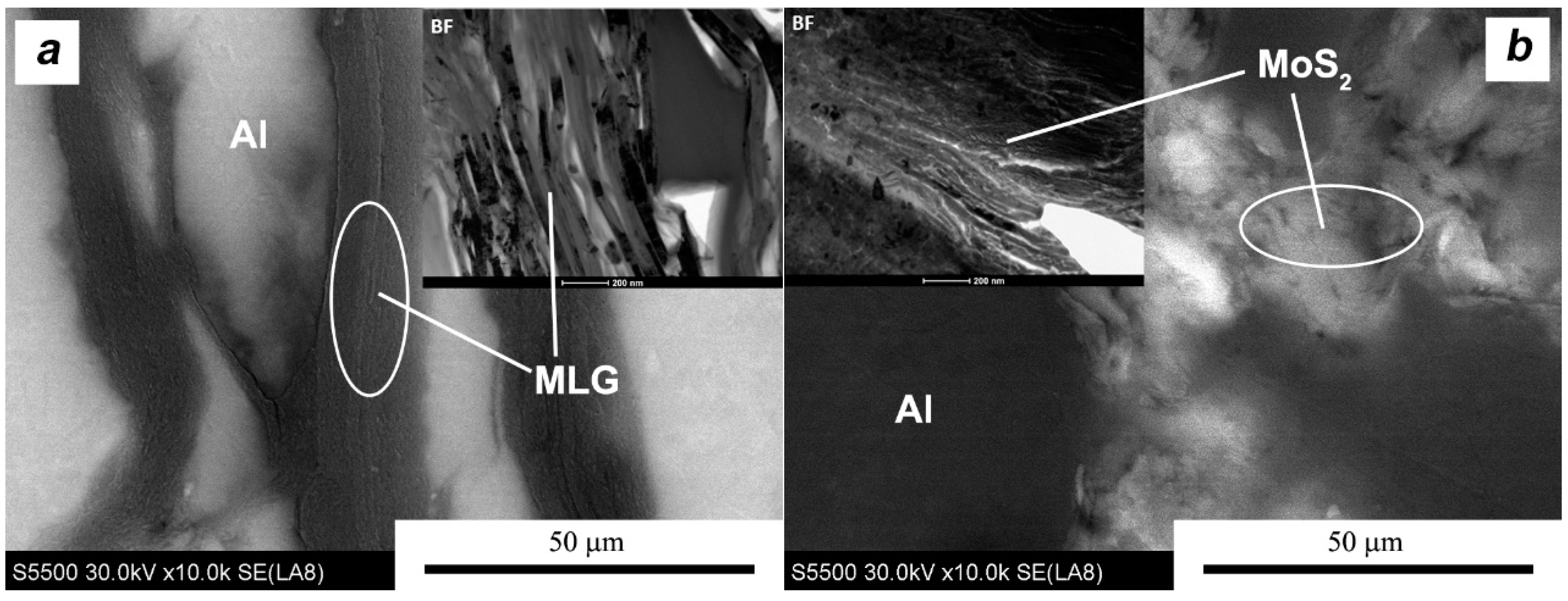
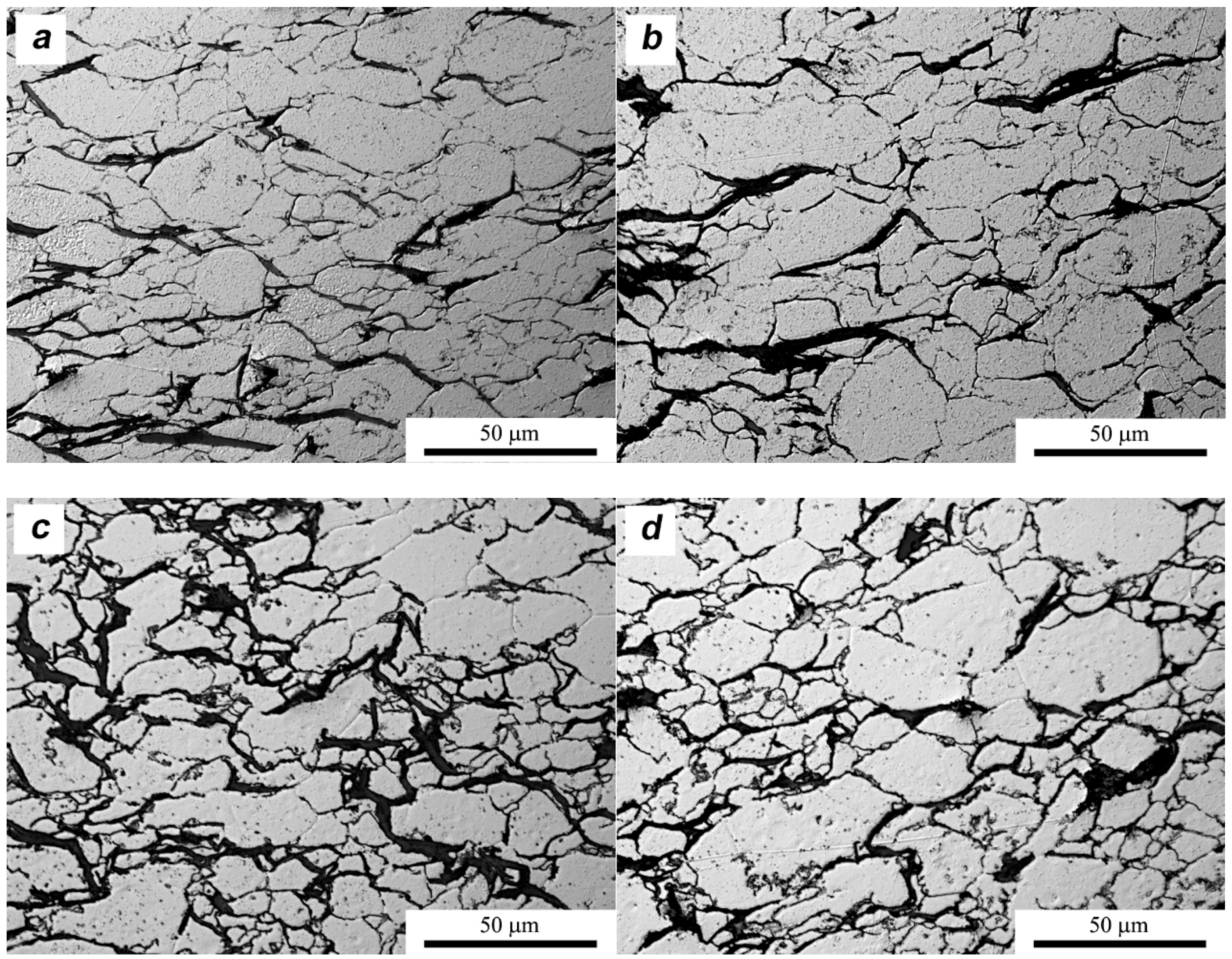
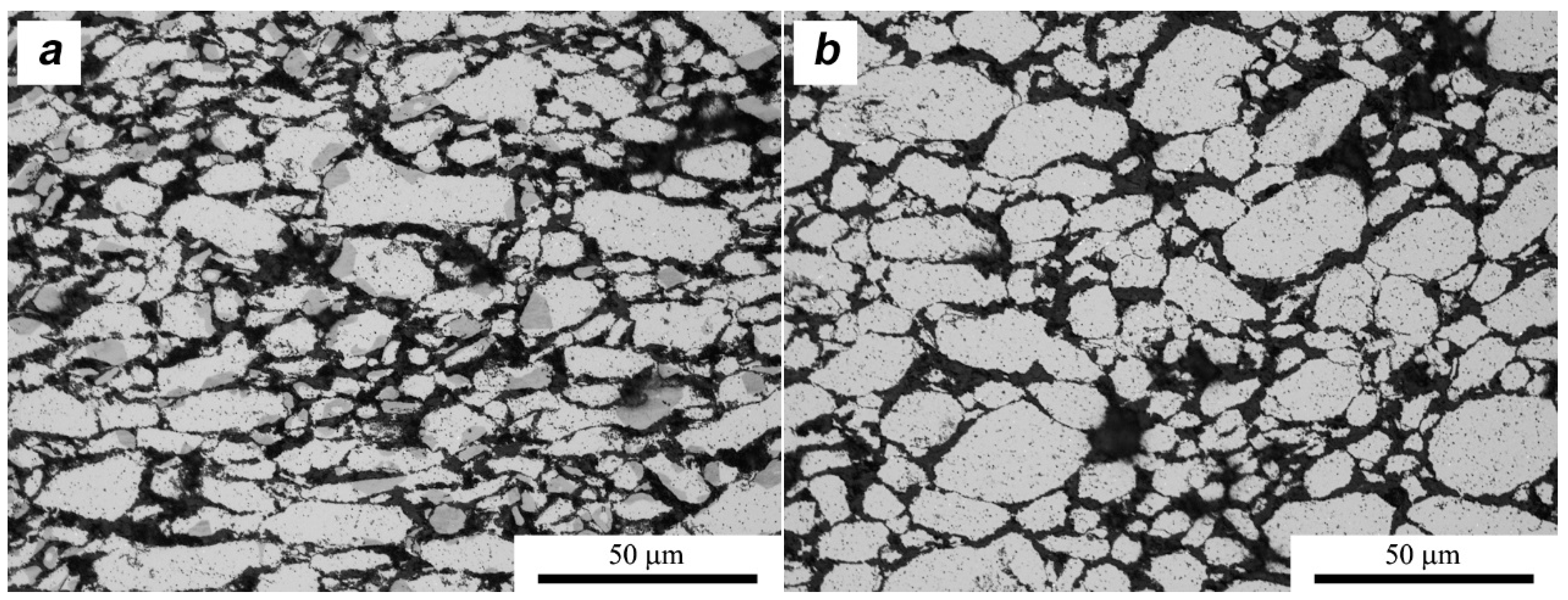
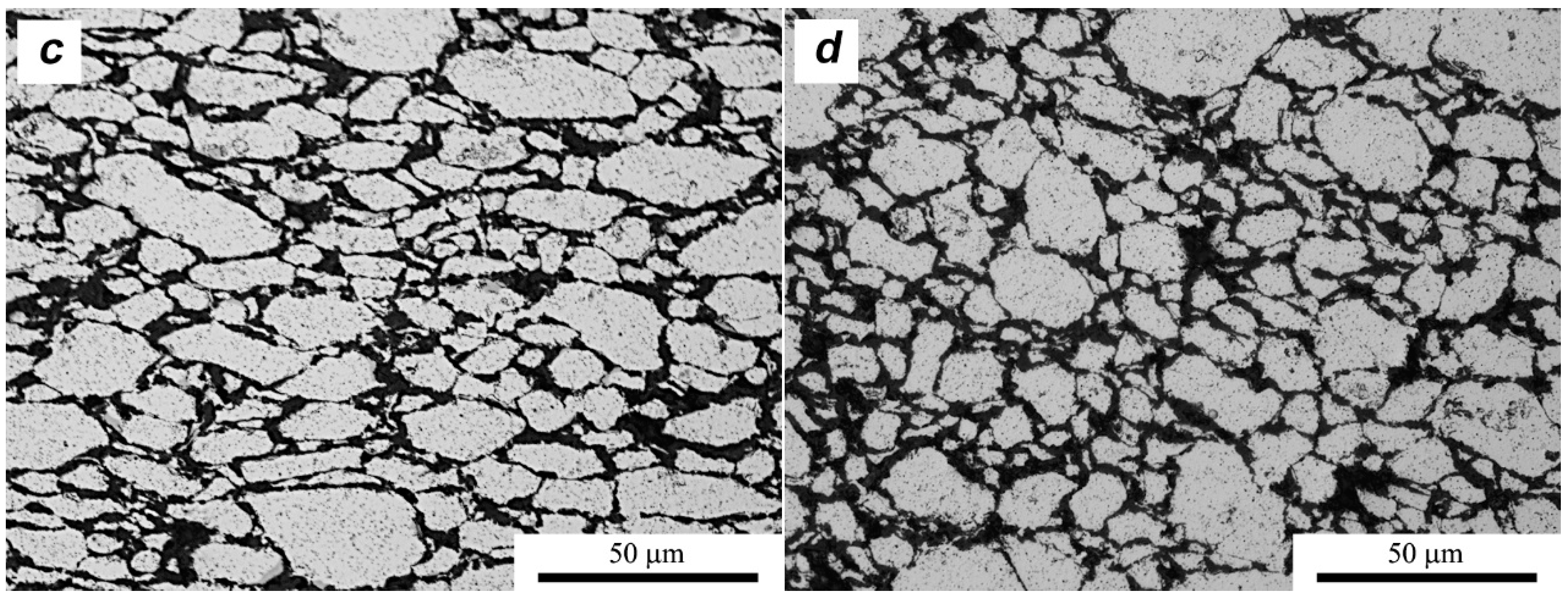
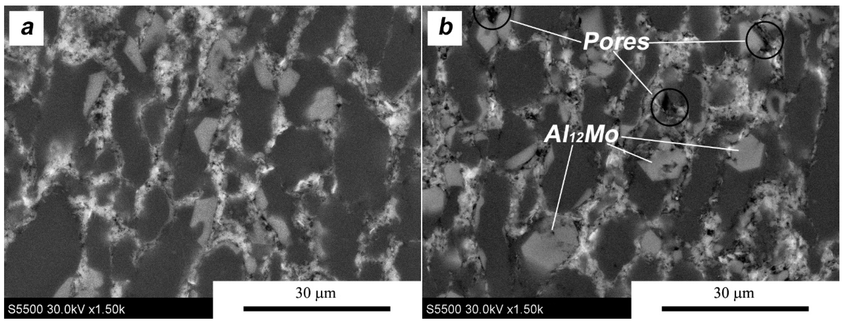
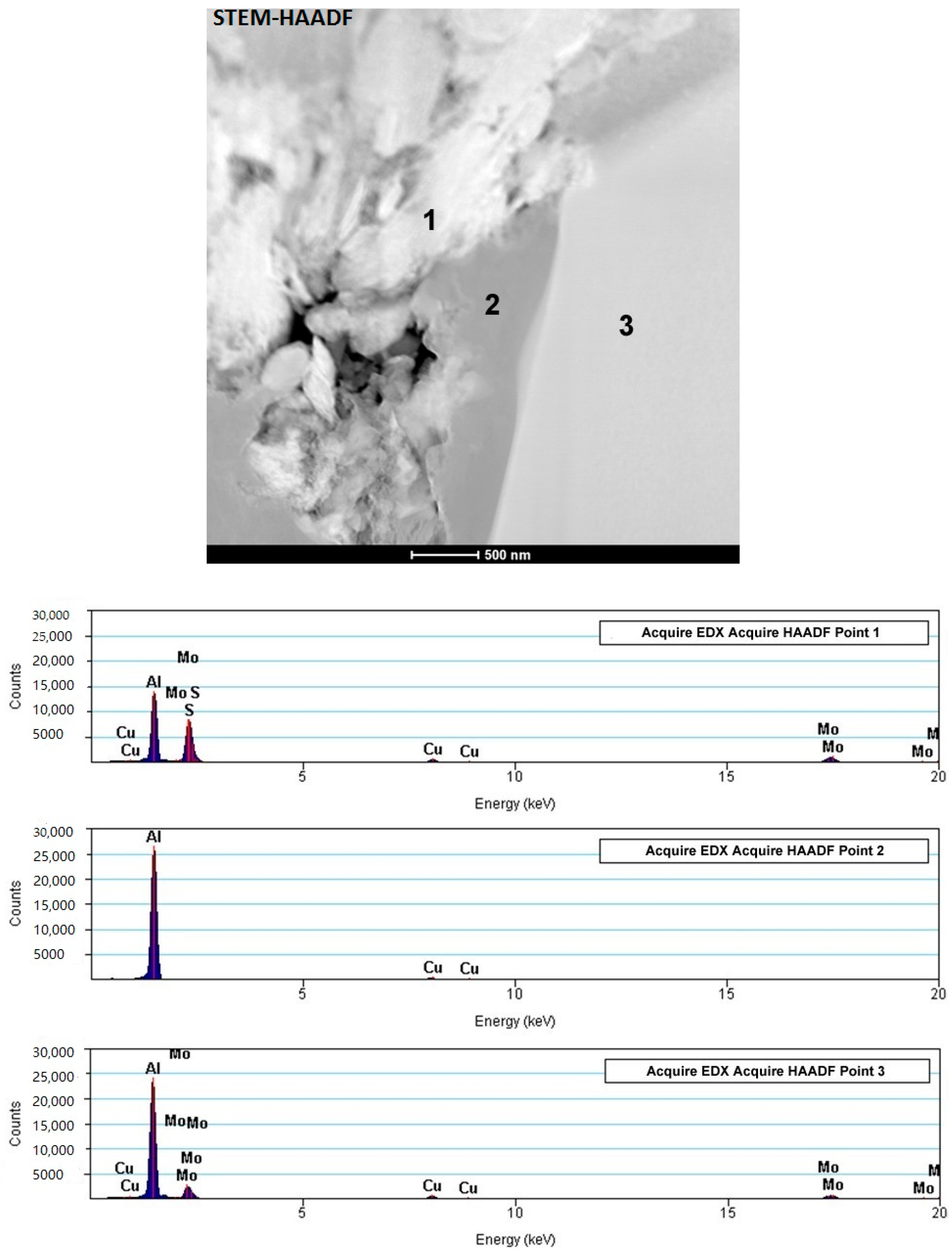
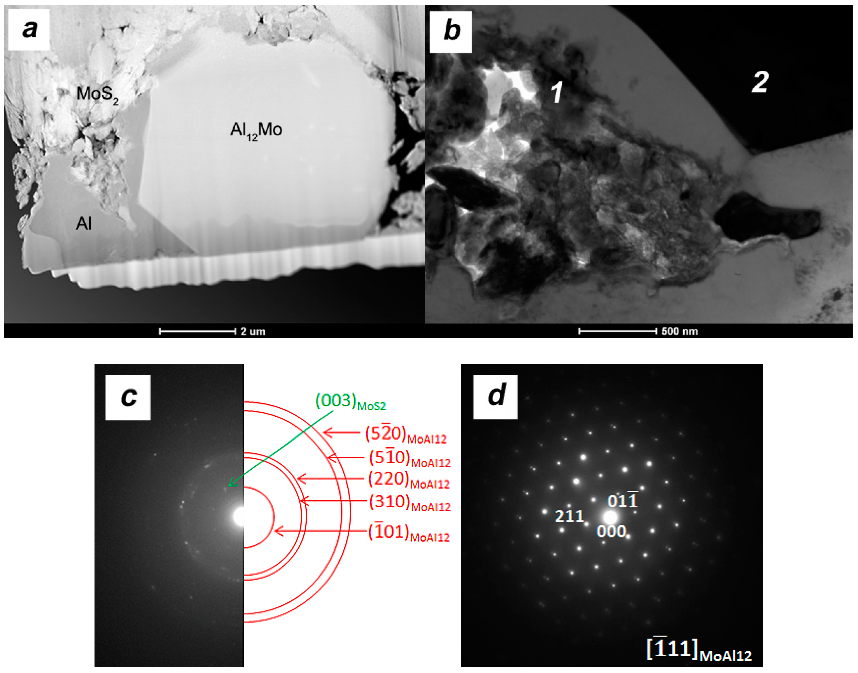
3.3. Microstructure
4. Conclusions
Author Contributions
Funding
Conflicts of Interest
References
- Huang, X.; Yin, Z.; Wu, S.; Qi, X.; He, Q.; Zhang, Q.; Yan, Q.; Boey, F.; Zhang, H. Graphene-Based Materials: Synthesis, Characterization, Properties, and Applications. Small 2011, 7, 1876–1902. [Google Scholar] [CrossRef] [PubMed]
- Hu, Z.; Tong, G.; Lin, D.; Chen, C.; Guo, H.; Xu, J.; Zhou, L. Graphene-reinforced metal matrix nanocomposites—A review. Mater. Sci. Technol. 2016, 32, 930–953. [Google Scholar] [CrossRef]
- Coleman, J.N.; Lotya, M.; O’Neill, A.; Bergin, S.D.; King, P.J.; Khan, U.; Young, K.; Gaucher, A.; De, S.; Smith, R.J.; et al. Two-dimensional nanosheets produced by liquid exfoliation of eayered materials. Science 2011, 331, 568–571. [Google Scholar] [CrossRef] [PubMed]
- Wozniak, J.; Kostecki, M.; Cygan, T.; Buczek, M.; Olszyna, A. Self-lubricating aluminium matrix composites reinforced with 2D crystals. Compos. Part B 2017, 111, 1–9. [Google Scholar] [CrossRef]
- Zalaznik, M.; Kalin, M.; Novak, S.; Jakša, G. Effect of the type, size and concentration of solid lubricants on the tribological properties of the polymer PEEK. Wear 2016, 364–365, 31–39. [Google Scholar] [CrossRef]
- Lee, C.G.; Hwang, Y.J.; Choi, Y.M.; Lee, J.K.; Choi, C.; Oh, J.M. A Study on the tribological characteristics of graphite nano lubricants. Int. J. Precis. Eng. Manuf. 2009, 10, 85–90. [Google Scholar] [CrossRef]
- Rashad, M.; Pan, F.; Yu, Z.; Asif, M.; Lin, H.; Pan, R. Investigation on microstructural, mechanical and electrochemical properties of aluminium composites reinforced with graphene nanoplatelets. Prog. Nat. Sci. Mater. Int. 2015, 25, 460–470. [Google Scholar] [CrossRef]
- Shahil, K.M.F.; Balandin, A.A. Thermal properties of graphene and multilayer graphene: Applications in thermal interface materials. Solid State Commun. 2012, 152, 1331–1340. [Google Scholar] [CrossRef]
- Wejrzanowski, T.; Grybczuk, M.; Chmielewski, M.; Pietrzak, K.; Kurzydlowski, K.J.; Strojny-Nedza, A. Thermal conductivity of metal-graphene composites. Mater. Des. 2016, 99, 163–173. [Google Scholar] [CrossRef]
- Hahm, M.G.; Nam, J.; Choi, M.; Park, C.D.; Cho, B.; Kazunori, S.; Kim, Y.A.; Kim, D.Y.; Endo, M.; Kim, D.H.; et al. Low interfacial contact resistance of Al-graphene composites via interface engineering. Nanotechnology 2015, 26, 215603. [Google Scholar] [CrossRef] [PubMed]
- Chyada, F.A.; Jabur, A.R.; Alwan, H.A. Effect addition of graphene on electrical conductivity and tensile strength for recycled electric power transmission wires. Energy Procedia 2017, 119, 121–130. [Google Scholar] [CrossRef]
- D’Aloia, A.G.; Marra, F.; Tamburrano, A.; De Bellis, G.; Sarto, M.S. Electromagnetic absorbing properties of graphene–polymer composite shields. Carbon 2014, 73, 175–184. [Google Scholar] [CrossRef]
- Moghadam, A.D.; Schultz, B.F.; Ferguson, J.B.; Omrani, E.; Rohatgi, P.K.; Gupta, N. Functional metal matrix composites: Self-lubricating, self-healing, and nanocomposites—An outlook. JOM 2014, 66, 872–881. [Google Scholar] [CrossRef]
- Arnell, R.D.; Davies, P.B.; Halling, J.; Whomes, T.L. Tribology—Principles and Design Applications; Macmillan: London, UK, 1991; pp. 105–107. [Google Scholar]
- Singh, J.; Chauhan, A. Characterization of hybrid aluminum matrix composites for advanced applications—A review. J. Mater. Res. Technol. 2016, 5, 159–169. [Google Scholar] [CrossRef]
- Nouguier-Lehon, C.; Cambou, B.; Vincens, E. Influence of particle shape and angularity on the behaviour of granular materials: A numerical analysis. Int. J. Numer. Anal. Methods Geomech. 2003, 27, 1207–1226. [Google Scholar] [CrossRef]
- Li, Y.; Ramesh, K.T. Influence of particle volume fraction, shape, and aspect ratio on the behavior of particle-reinforced metal–matrix composites at high rates of strain. Acta Mater. 1998, 46, 5633–5646. [Google Scholar] [CrossRef]
- Bains, P.S.; Sidhu, S.S.; Payal, H.S. Fabrication and Machining of Metal Matrix Composites: A Review. Mater. Manuf. Processes 2016, 31, 553–573. [Google Scholar] [CrossRef]
- Orru, R.; Licheri, R.; Locci, A.M.; Cincotti, A.; Cao, G. Consolidation/synthesis of materials by electric current activated/assisted sintering. Mater. Sci. Eng. R 2009, 63, 127–287. [Google Scholar] [CrossRef]
- Xie, G.; Ohashi, O.; Song, M.; Furuya, K.; Noda, T. Behavior of oxide film at the interface between particles in sintered Al powders by pulse electric-current sintering. Metall. Mater. Trans. A 2003, 34, 699–703. [Google Scholar] [CrossRef]
- Srivatsan, T.S. Processing techniques for particulate-reinforced metal aluminium matrix composites. J. Mater. Sci. 1991, 26, 5965–5978. [Google Scholar] [CrossRef]
- Kostecki, M.; Woźniak, J.; Cygan, T.; Petrus, M.; Olszyna, A. Tribological properties of aluminium alloy composites reinforced with multi-layer grapheme—The influence of spark plasma texturing process. Materials 2017, 10, 928. [Google Scholar] [CrossRef] [PubMed]
- Kuhlman, G.W. Forging of Aluminum Alloys. In Metalworking: Bulk Forming; Semiatin, S.L., Ed.; ASM Handbook: Materials Park, OH, USA, 2005; Volume 14A, pp. 299–312. [Google Scholar]
- Tünçay, M.M.; Muñiz-Lerma, J.A.; Bishop, D.P.; Brochu, M. Spark Plasma Sintering and Upsetting of a Gas-Atomized/Air-Atomized Al Alloy Powder Mixture. J. Mater. Eng. Perform. 2017, 26, 5097–5106. [Google Scholar] [CrossRef]
- Hu, Z.; Chu, L.; Li, J. Enhanced magnetic properties in Nd-Fe-B magnets prepared by spark plasma sintering via die-upsetting process. J. Rare Earths 2011, 29, 660–663. [Google Scholar] [CrossRef]
- Noudem, J.G. A new process for lamellar texturing of thermoelectric Ca3Co4O9 oxides by spark plasma sintering. J. Eur. Ceram. Soc. 2009, 29, 2659–2663. [Google Scholar] [CrossRef]
- Wei, X.; Maximenko, A.L.; Back, C.; Izhvanov, O.; Olevsky, E.A. Effects of loading modes on densification efficiency of spark plasma sintering: Sample study of zirconium carbide consolidation. Philos. Mag. Lett. 2017, 97, 265–272. [Google Scholar] [CrossRef]
- Kostecki, M.; Jezierska, E. Influence of milling media on mechanically exfoliated MoS2. Nanomater. Nanotechnol. 2014, 4, 32. [Google Scholar] [CrossRef]
- Kajtoch, J. Strain in the upsetting Process. Metall. Foundry Eng. 2007, 33, 51–61. [Google Scholar] [CrossRef]
- Buckingham, R.C.; Argyrakis, C.; Hardy, M.C.; Birosca, S. The effect of strain distribution on microstructural developments during forging in a newly developed nickel base superalloy. Mater. Sci. Eng. A 2016, 654, 317–328. [Google Scholar] [CrossRef]
- Gandi, A.N.; Schwingenschlogl, U. Thermal conductivity of bulk and monolayer MoS2. EPL 2016, 113, 36002. [Google Scholar] [CrossRef]
- Adam, J.; Rich, J.B. The crystal structure of WAl12, MoAl12 and (Mn,Cr)Al12. Acta Cryst. 1954, 7, 813–816. [Google Scholar] [CrossRef]
- Walford, L.K. The structures of the intermetallic phases MoAl12, ReAl12, and TcAl12. Acta Cryst. 1964, 17, 57–59. [Google Scholar] [CrossRef]
- Piątkowski, J. Development of the fundamentals of melting and casting technology of Al-Me (Cr,Ni, Mo,W,Ti) master alloys used for modification of microstructure in silumins. Arch. Foundry Eng. 2009, 9, 17–20. [Google Scholar]
- Kazakova, E.F.; Loboda, T.P.; Rusnyak, Y.I. Formation of supersaturated solid solutions in aluminium alloys with Mo, Ti, Zr, and Cr. Met. Sci. Heat Treat. 2009, 51, 9–10. [Google Scholar] [CrossRef]
- Liu, D.; Chen, X.; Li, D.; Wang, F.; Luo, X.; Yang, B. Simulation of MoS2 crystal structure and the experimental study of thermal decomposition. J. Mol. Struct. 2010, 980, 66–71. [Google Scholar] [CrossRef]
- Zhang, X.; Jia, F.; Yang, B.; Song, S. Oxidation of Molybdenum Disulfide Sheet in Water under in Situ Atomic Force Microscopy Observation. J. Phys. Chem. C 2017, 121, 9938–9943. [Google Scholar] [CrossRef]


| Chemical Composition | Content (wt %) |
|---|---|
| Cu | 0.272 |
| Mn | 0.011 |
| Mg | 1.04 |
| Fe | 0.111 |
| Si | 0.634 |
| Zn | 0.001 |
| Cr | 0.179 |
| Ni | 0.006 |
| Ti | 0.006 |
| Al | remained |
| SPS | SPT | ||
|---|---|---|---|
| Stage I | Stage II | ||
| Temperature (°C) | 550 | 300 | 550 |
| Die diameter (mm) | 20 | 20 | 30/40 |
| Pressing time (min) | 4 | 2 | 6/8 |
| Atmosphere | Argon | Argon | Argon |
| Heating rate (°C/min) | 100 | 150 | 100 |
| Pressing force (kN) | 16 | 3 | 35/63 |
| Material | SPS λ = 1 | SPT λ = 1.5 | SPT λ = 2 | |||
|---|---|---|---|---|---|---|
| d2 (μm)/(SD) | α | d2 (μm) Center/Edge (SD) | α Center/edge | d2 (μm) Center/Edge(SD) | α Center/Edge | |
| AA6061 | 10.3/(6.7) | 1.4 | - | - | - | - |
| AA6061/MLG 10 vol % | 10.2/(6.7) | 1.7 | 10.6/8.8 (7.2/6.5) | 1.7/1.4 | 7.1/8.4 (5.1/6.3) | 1.6/1.5 |
| AA6061/MoS2 10 vol % | 8.8/(6.4) | 1.6 | 8.3/5.8 (6.5/5.4) | 1.8/1.5 | 10.1/6.3 (7.1/5.7) | 1.8/1.4 |
© 2018 by the authors. Licensee MDPI, Basel, Switzerland. This article is an open access article distributed under the terms and conditions of the Creative Commons Attribution (CC BY) license (http://creativecommons.org/licenses/by/4.0/).
Share and Cite
Kostecki, M.; Petrus, M.; Woźniak, J.; Cygan, T.; Olszyna, A. Closed Die Upsetting of Aluminum Matrix Composites Reinforced with Molybdenum Disulfide Nanocrystals and Multilayer Graphene, Implemented using the SPS Process—Microstructure Evolution. Materials 2018, 11, 994. https://doi.org/10.3390/ma11060994
Kostecki M, Petrus M, Woźniak J, Cygan T, Olszyna A. Closed Die Upsetting of Aluminum Matrix Composites Reinforced with Molybdenum Disulfide Nanocrystals and Multilayer Graphene, Implemented using the SPS Process—Microstructure Evolution. Materials. 2018; 11(6):994. https://doi.org/10.3390/ma11060994
Chicago/Turabian StyleKostecki, Marek, Mateusz Petrus, Jarosław Woźniak, Tomasz Cygan, and Andrzej Olszyna. 2018. "Closed Die Upsetting of Aluminum Matrix Composites Reinforced with Molybdenum Disulfide Nanocrystals and Multilayer Graphene, Implemented using the SPS Process—Microstructure Evolution" Materials 11, no. 6: 994. https://doi.org/10.3390/ma11060994