2.1. Parameter Development
Experimental trials based on simplified geometry features accompanied by metallographic investigations were conducted to sort out parameter sets suitable in terms of defect free build-ups and geometrical requirements (
Table 1).
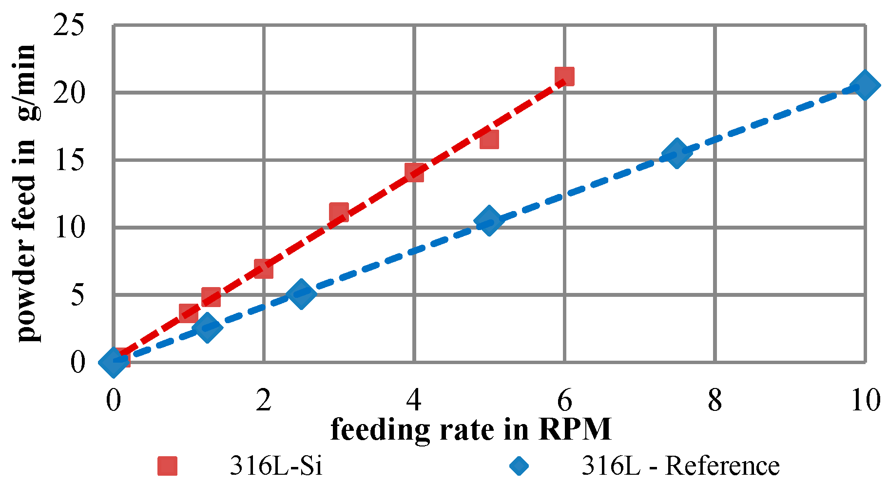
A disk powder feeder with a groove depth of 0.6 mm and a width of 5.0 mm was used. The parameter development was realized on the basis of single tracks and is composed of the following four steps:
material processing,
width adjustment,
height adjustment and
multilayer build-ups
The material processability was confirmed by producing single tracks with varying parameter sets. As recommended the powder was dried (3 h, 120 °C). The boundary condition for the second step was a desired track width of ~1 mm, chosen for reasons of stiffness, process stability, and machining time. Given that the track width primarily correlates with the laser power, several single tracks were welded and investigated with nonvarying parameters except for the laser power, which was decreased by 50 W track by track beginning at 600 W. A laser power of 550 W with a feed of 600 mm/min and a powder feed of 6 g/min delivered the required track width.
Next, the powder feed of the previous determined parameter set was varied to adjust the track height. The proposed track height to width ratio was 1/3 to 1/2 in order to guarantee a suitable accuracy as well as build-up rate. It was found that a powder feed of 4.16 g/min complied with the guideline.
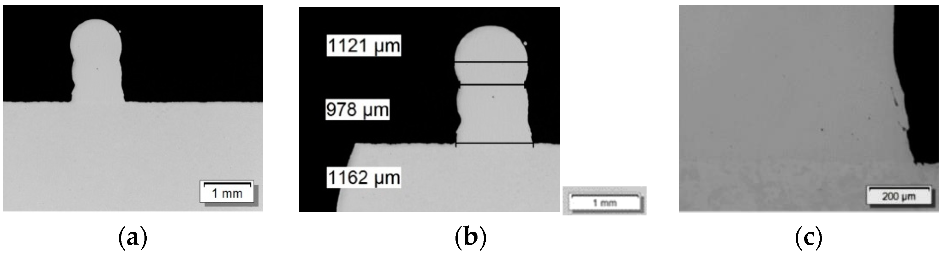
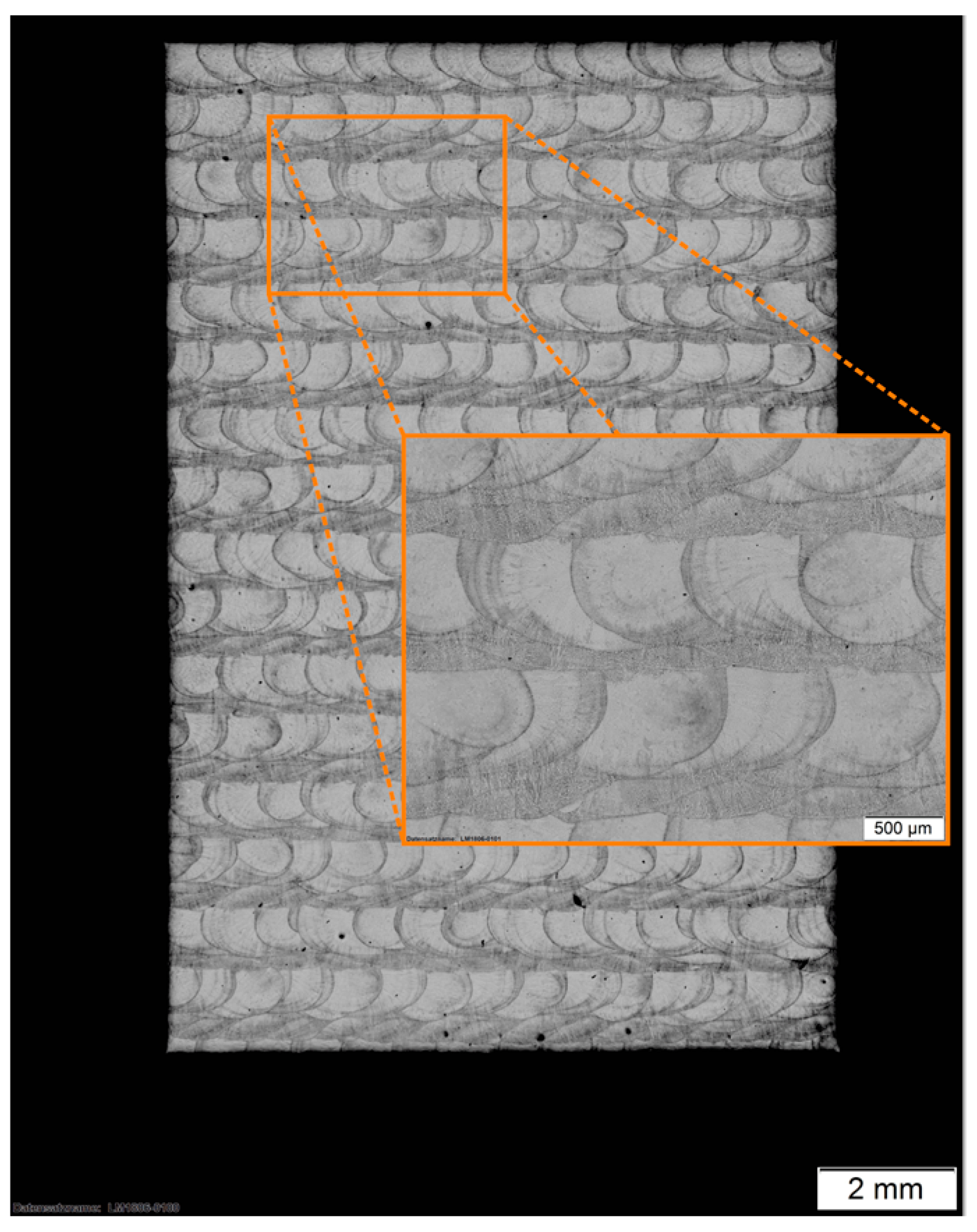
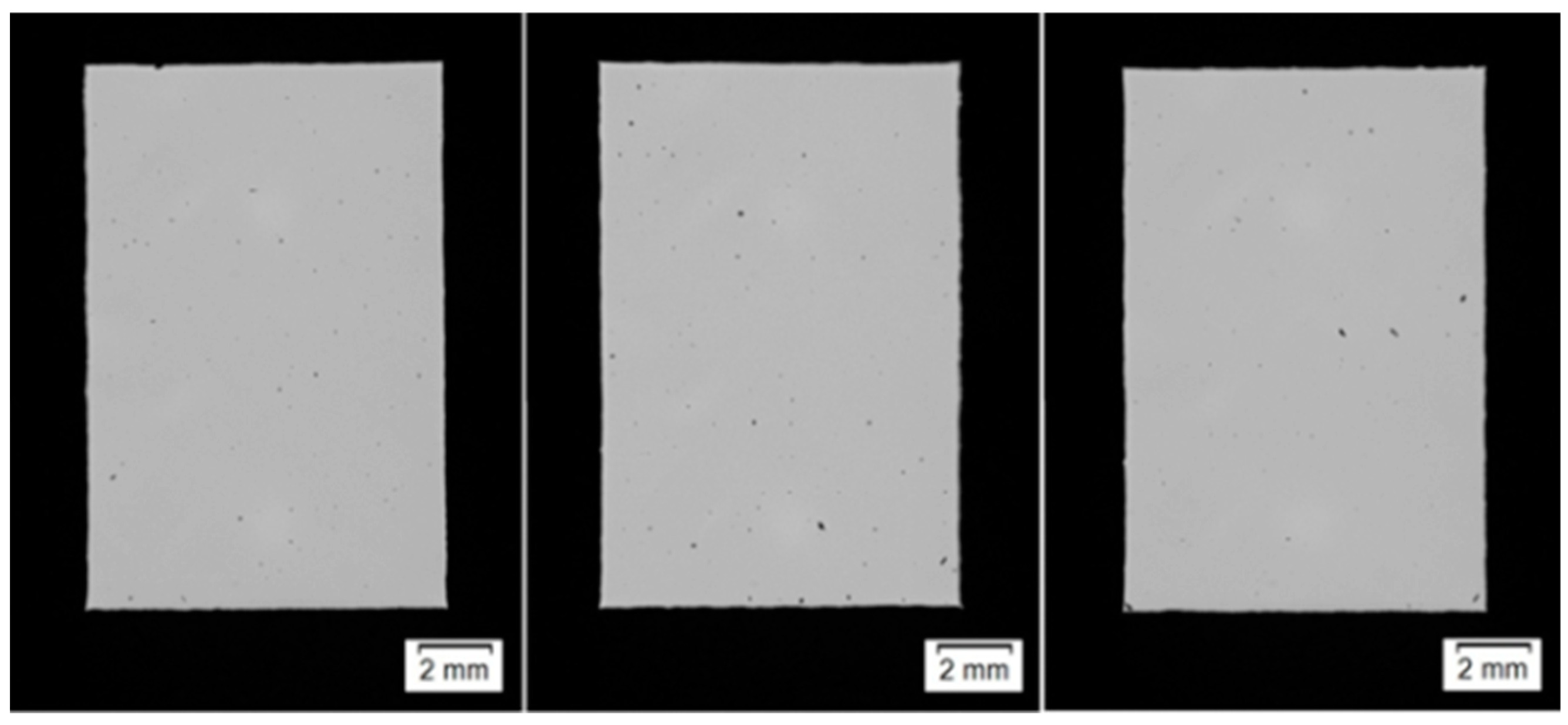
Concluding, multilayer build-ups were realized using the developed parameter set in order to examine the steadiness of the process. The build-ups with the required height were metallographically investigated for cracks or pores and their size (
Figure 4). The determined parameter sets were kept constant throughout the complete process development.
2.3. Powder and Material Characterization
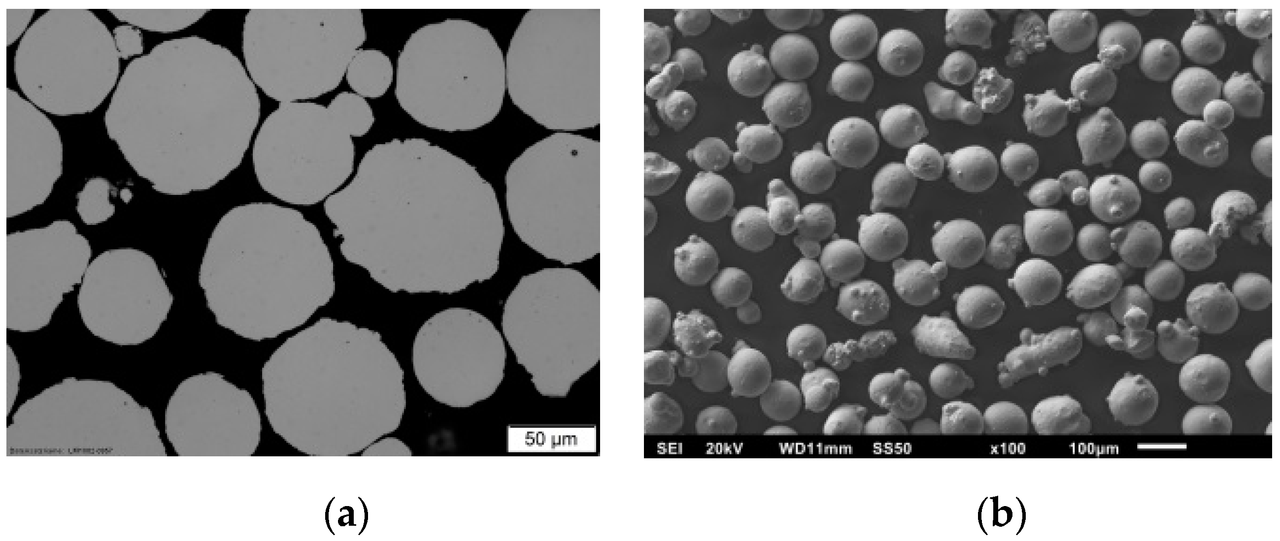
Since the powder specifications play a major role in the laser-particle interaction within the additive manufacturing process, the build-up quality will be strongly affected by the powder material. Hence, the process stability as well as the quality of the flexure pivots will be ensured by means of a comprehensive power characterization, including: chemical composition, morphology, and rheology.
The used material for the build-up is the austenitic stainless steel powder Oerlikon Metcoclad 316L-Si which is similar to the AISI-Type 316L steel, modified only by an increased silicon level. The silicon acts as fluxing agent during the welding process and leads to a better deposition quality [
11].
The chemical composition of the powder was investigated by energy dispersive X-ray spectroscopy (EDX, Oxford instruments, Oxford, UK) and inductively coupled plasma optical emission spectrometry (ICP-OES, SPECTRO Analytical Instruments GmbH, Kleve, Germany) to ensure that alloying elements are within specification. The EDX measurement gives an overview of the alloying elements but is relatively inaccurate in the case of light and highly conductive elements like Al and Si. Therefore, an ICP-OES was performed to validate the chemical composition.
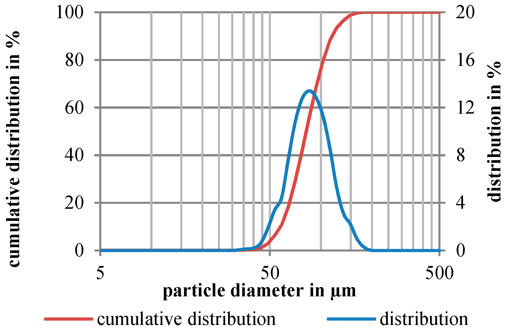
For characterization of the powder morphology, the particle size distribution (PSD) was determined with laser diffraction spectroscopy (Mastersizer 2000, Malvern Panalytical Ltd, Malvern, Worcestershire, UK) according to ISO 13320-1 [
12] and metallographic imaging by optical and scanning electron microscopy.
For a more reliable assessment of the processed powder, further rheological measurements were performed with the Hall flow test [
13] as well as the stability and variable flow test and shear tests with a Freeman Technology-FT4 Powder Rheometer (Freeman Technology, Tewkesbury, UK) corresponding to ASTM D7891-15.
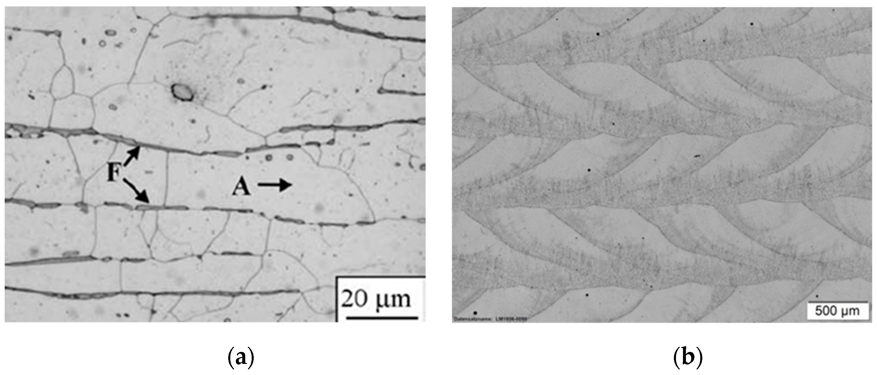
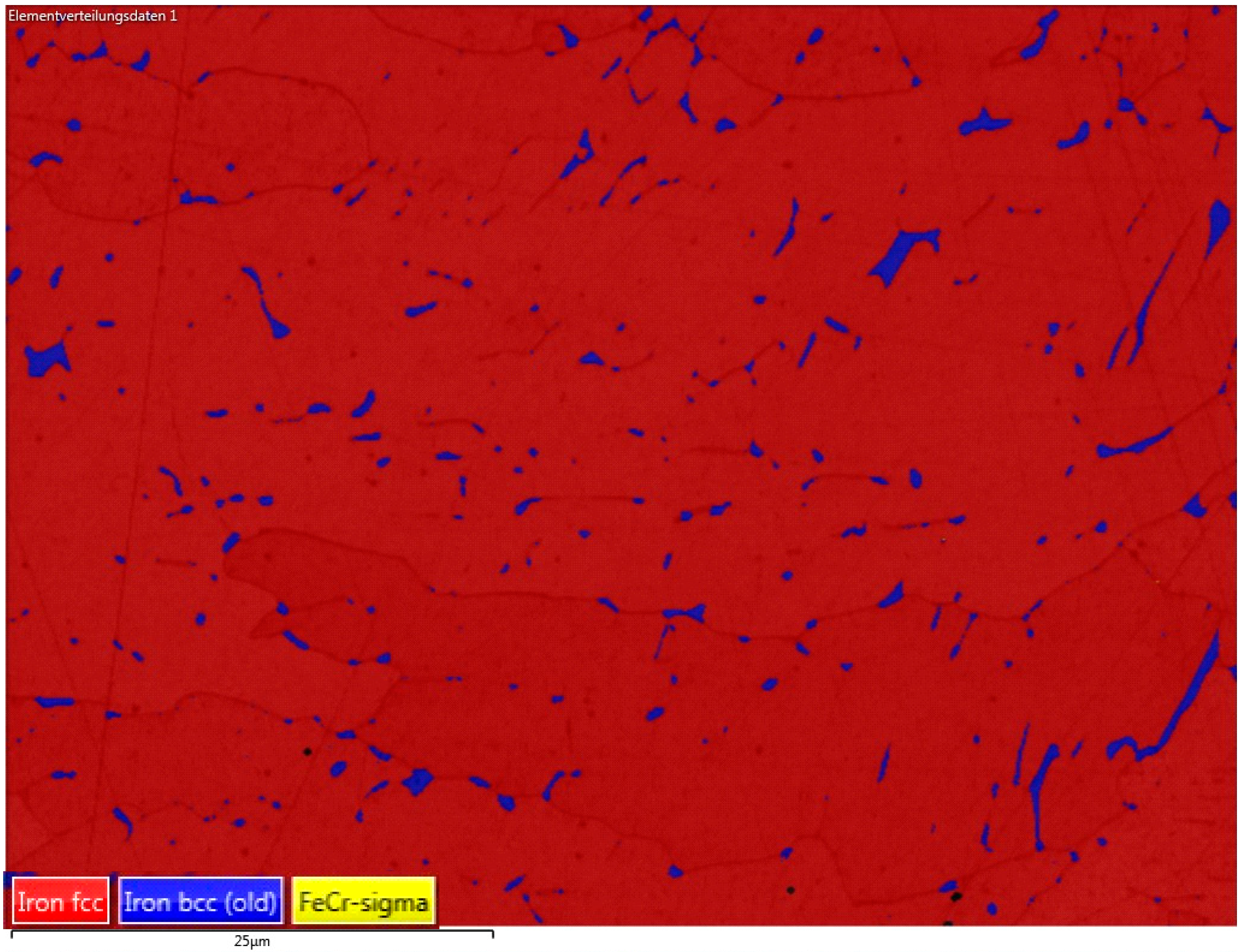
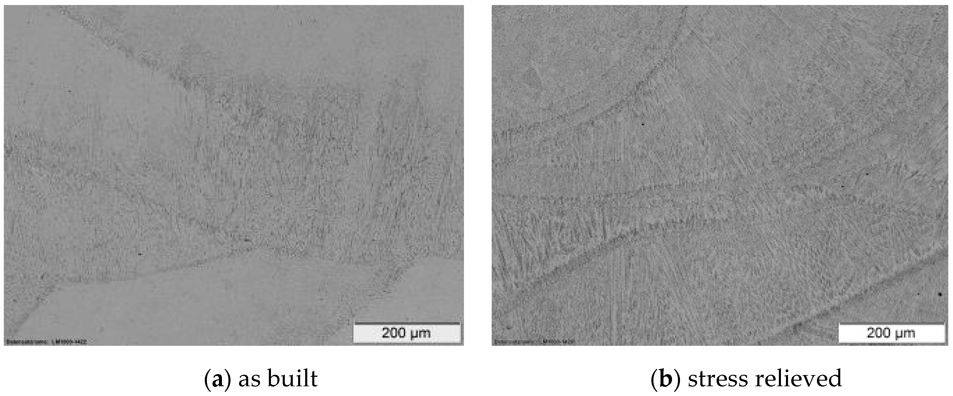
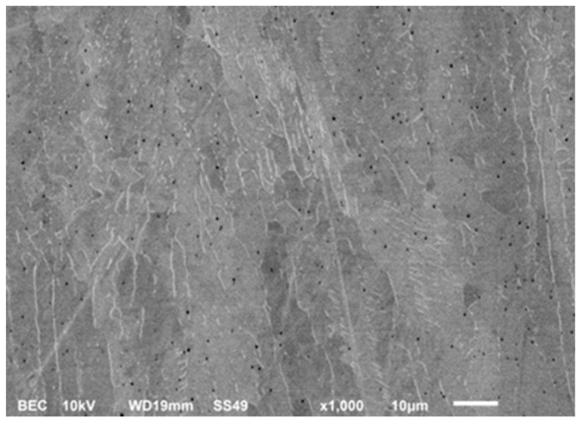
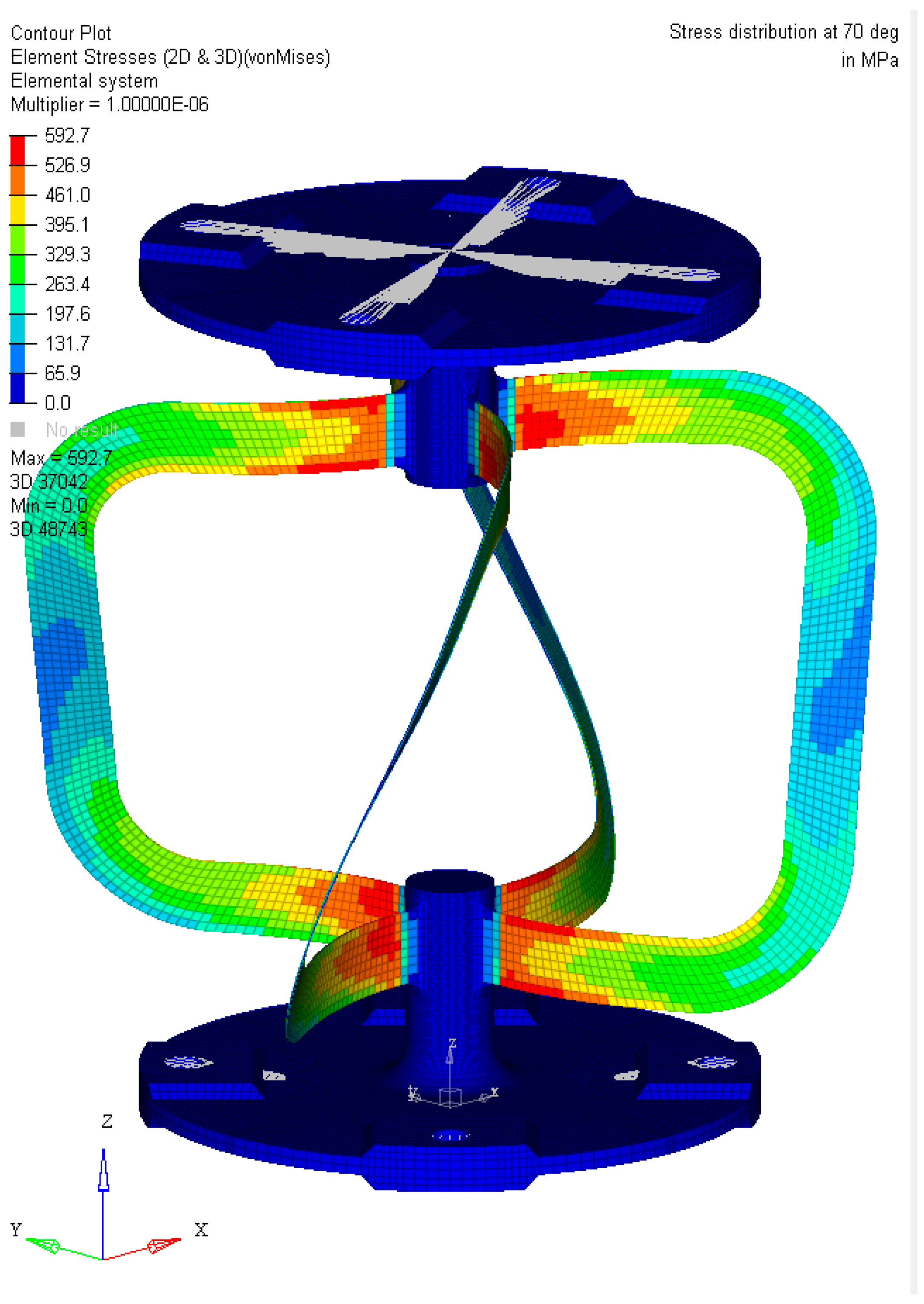
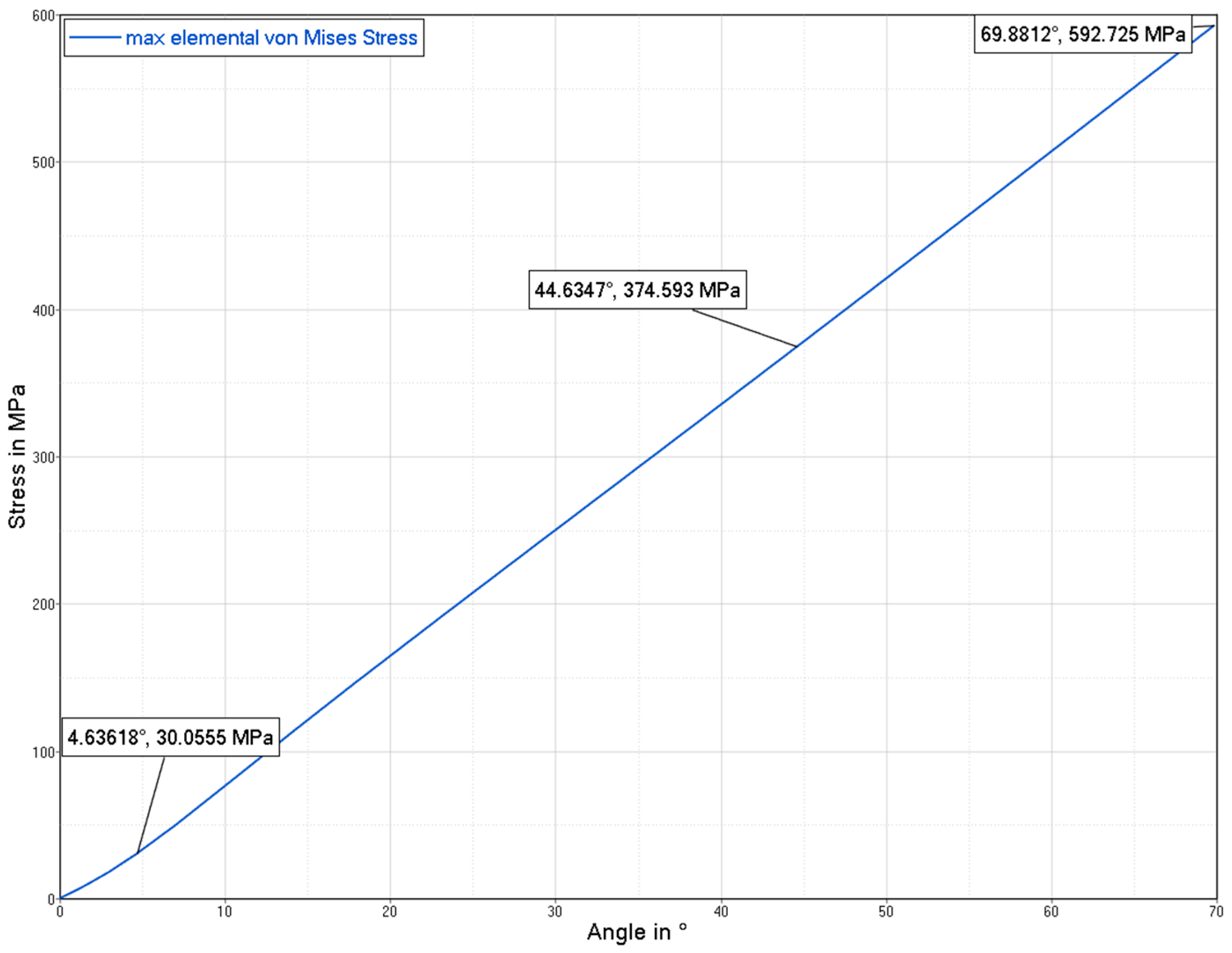
To evaluate the effect of the heat treatment, metallographic investigations via optical and electron microscopy were performed. For the microstructural investigation, the prepared samples were etched with V2A etchant and Kalling 2. For more detailed phase analysis an electron backscatter diffraction (EBSD) investigation was performed at an acceleration voltage of 20 kV, sample tilting of 70°, at a recording speed of 40.33 Hz.
The density measurement was performed in accordance with the Archimedean principle [
14] using 11 cuboid specimens with edge lengths of 10 × 10 × 15 mm
3. The temperature and density of the water were held constant at 22.2 °C and 0.9977 g/cm
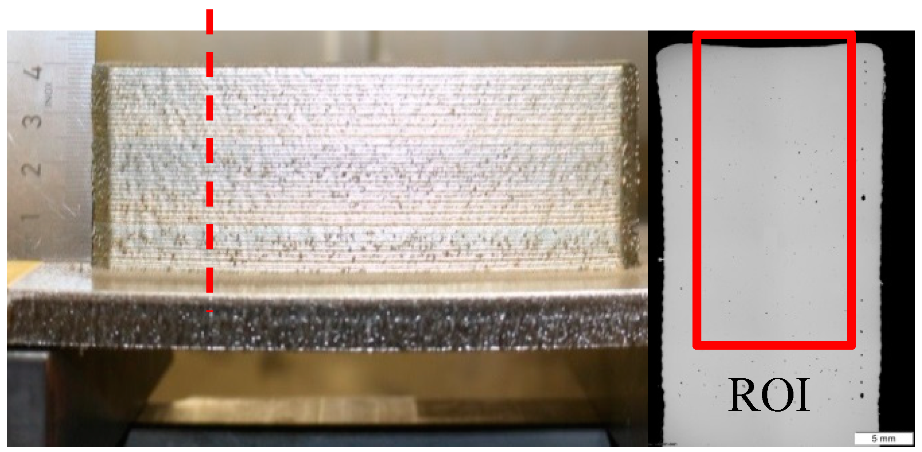
3. In addition, metallographic investigations of the cross sections of three sample cuboids were conducted and analyzed by quantitative image analysis according to [
15]. As tensile strength specimen geometry DIN 50, 125—E 3 × 8 × 30 [
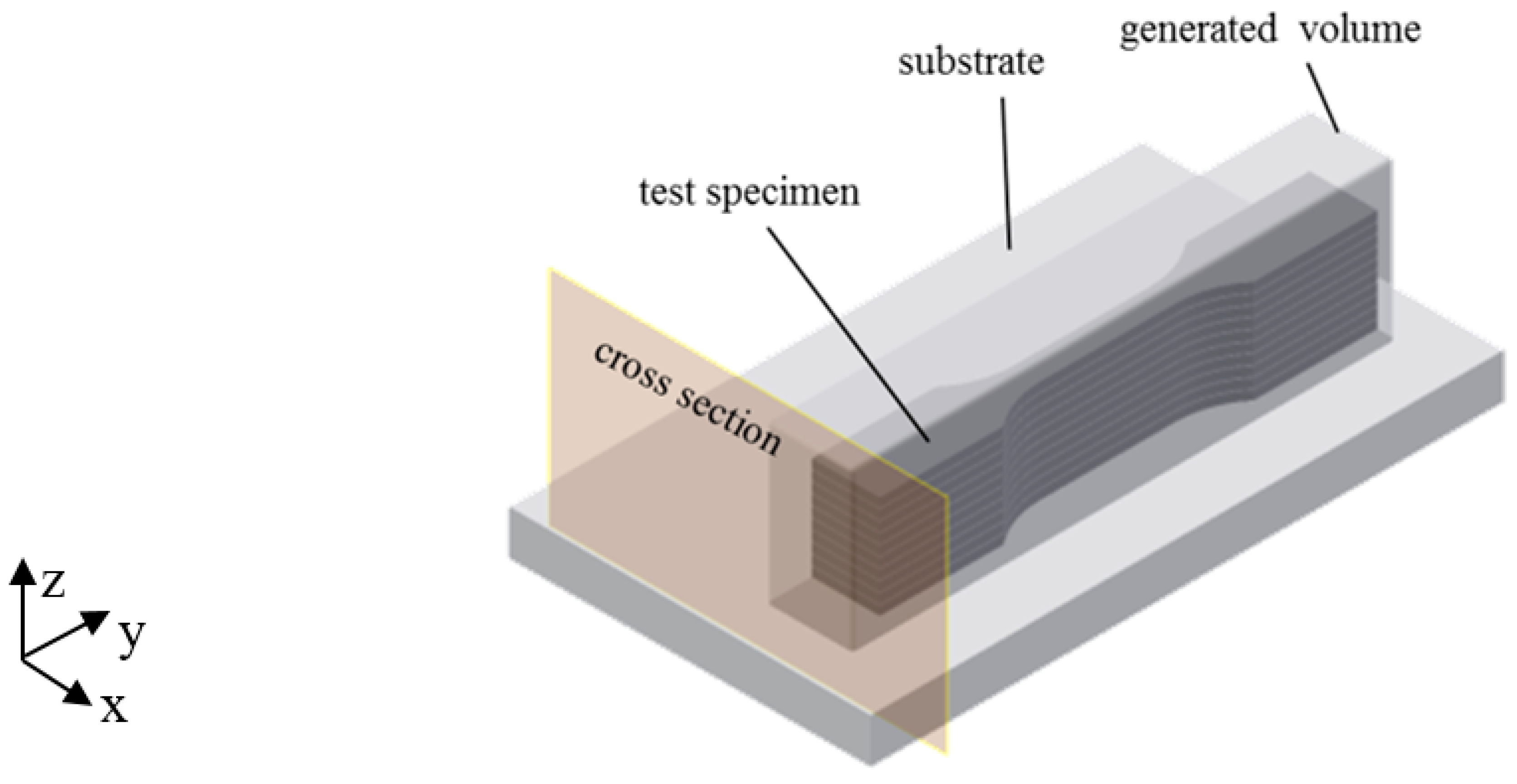
10] was chosen for reasons of beneficial build-up time, testability, and its representation of the blade geometry of the flexure pivot. The test direction is in the
x–
y plane of the build-up. The tensile tests were performed according to [
16] at room temperature at an H & P inspect Table 50 kN using test procedure A. The inspection speed was 5 mm/min. The test direction is in the
x-
y plane of the build-up.
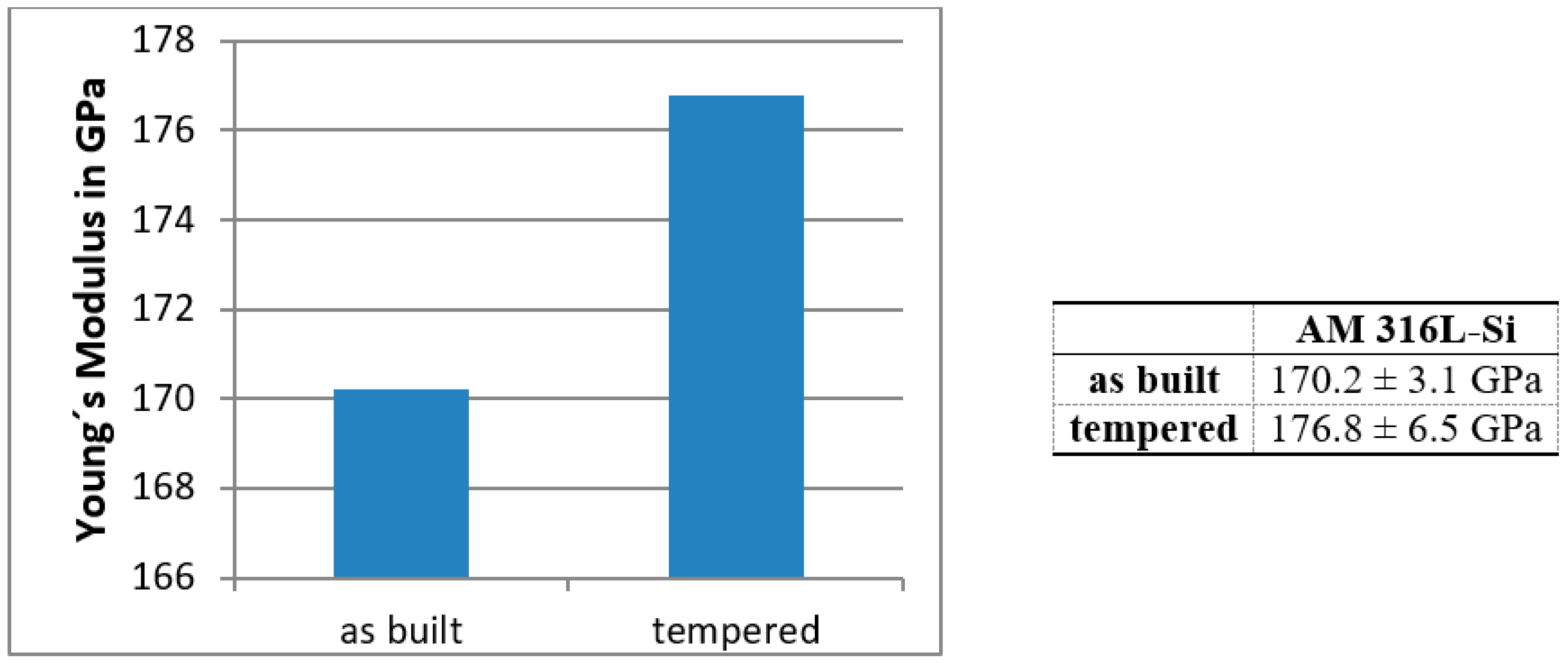
In addition to the aforementioned destructive tensile tests, the Young’s modulus is also measured by the nondestructive LAwave technique. It is based on the velocity measurement of laser-induced surface acoustic waves in dependence on their frequency to determine elastic properties, density, and thickness of films and surfaces [
17]. This method is widely used for the characterization of films and surfaces, i.e., coatings from PVD [
18,
19,
20], or thermal spraying [
21,
22,
23,
24].
Surface acoustic waves are elastic vibrations propagating along material surfaces. Their amplitude is highest at the surface and decays exponentially within the material. The velocity of the surface acoustic waves depends on the elastic properties and the density of the material. Furthermore, pores, cracks, segregations, texture, process or hardening layers, and other microstructural properties also influence the wave velocity. The penetration depth of the surface acoustic waves correlates with frequency. Waves with higher frequency propagate closer to the surface. For a completely homogeneous sample the wave velocity is constant for every frequency. The calculation of the wave velocity in dependence on frequency using a theory that contains the materials’ elastic constants and density [
25,
26] enables the determination of the Young’s modulus. Due to its limited penetration depth, LAwave is not suited for solid volumes. However, it could be applied as a nondestructive test for the flexure pivots since the blade thickness of 200 µm is very small. In addition, comparisons between different heat treatment states could be performed with a single sample.
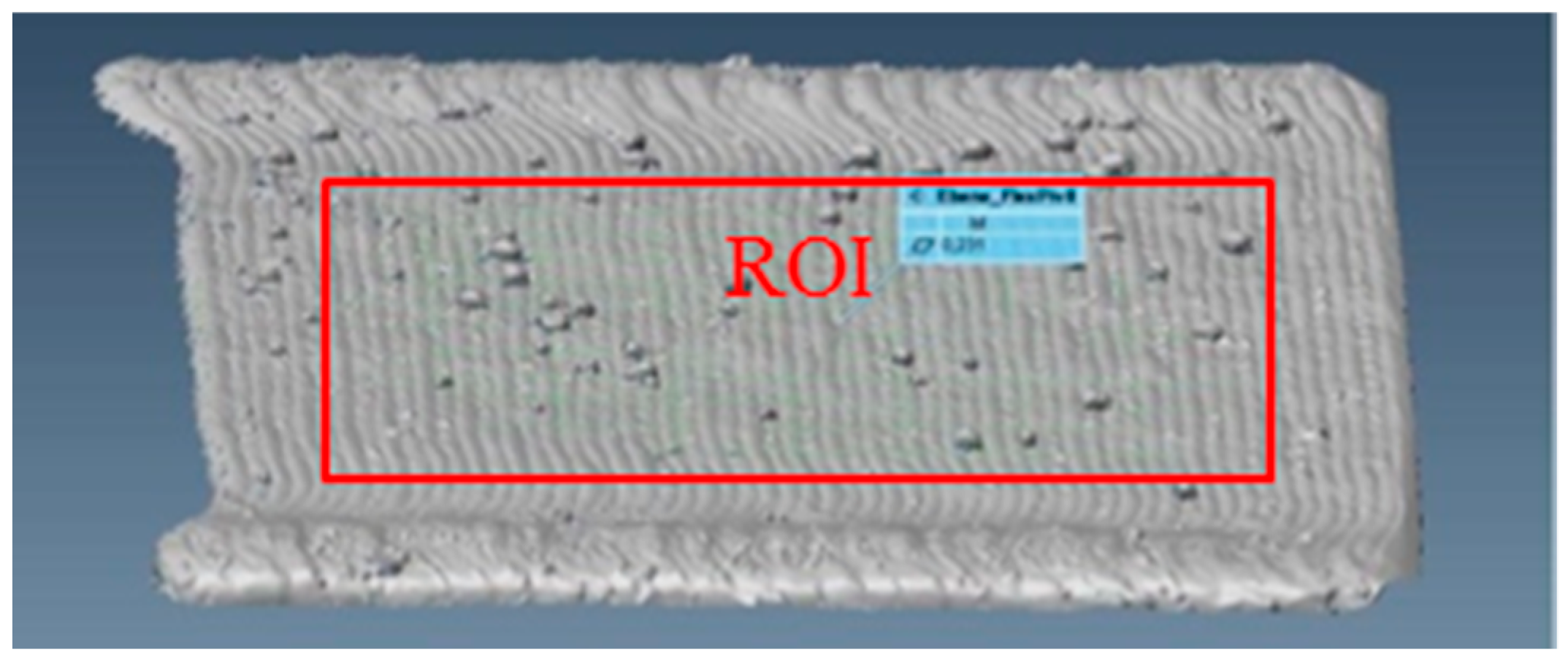
In this paper, shape deviations were evaluated by a new omnidirectional approach based on 3D scanning and laser scanning microscopy to calculate a reliable offset value for the flexure pivot blades for the postprocessing after the LMD process.
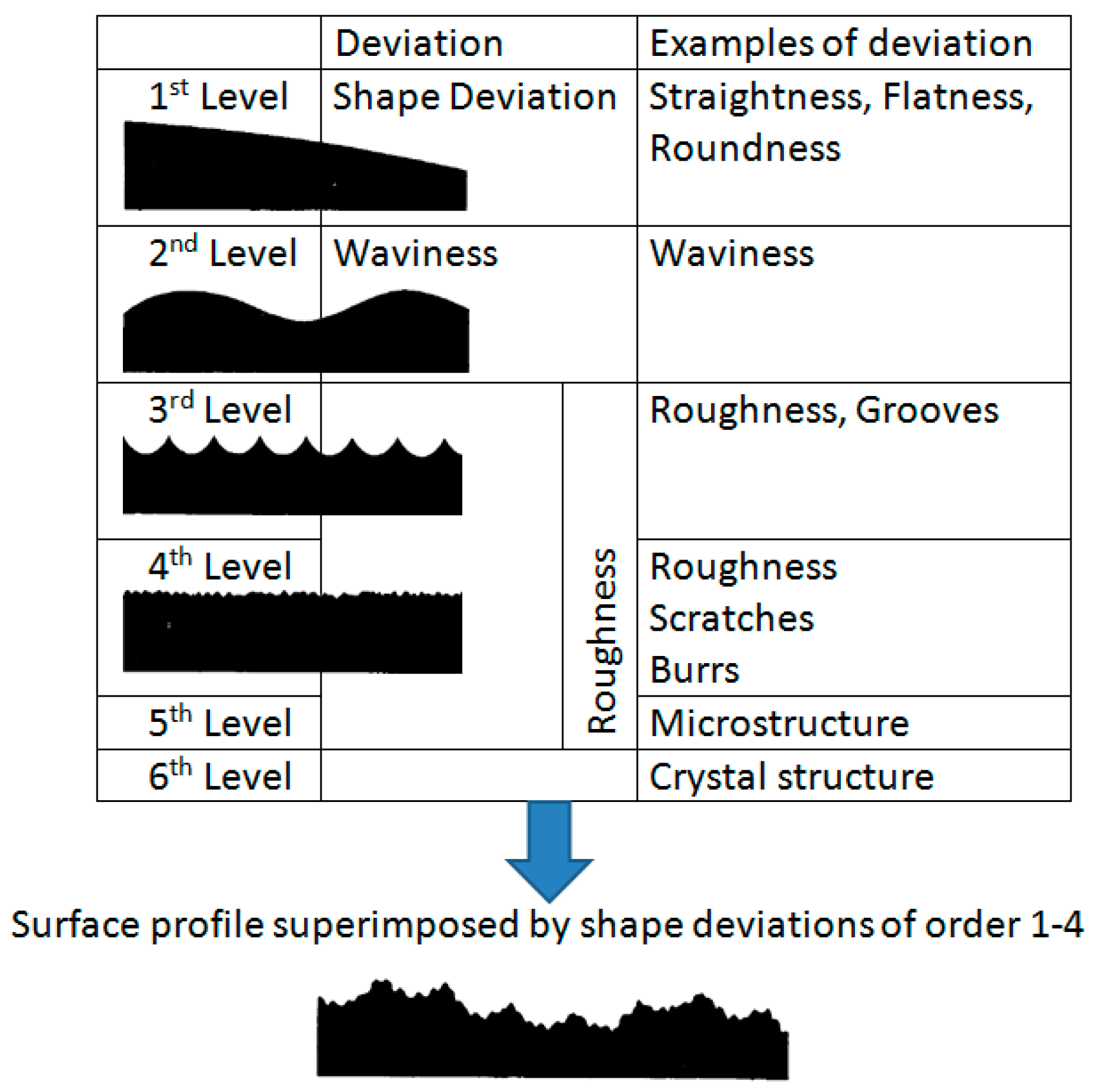
The surface quality or surface texture is influenced by deviations from the ideal plane on different surface levels classified in DIN 4760 [
27]. Possible deviations include shape deviation; waviness, and roughness (see
Figure 7).
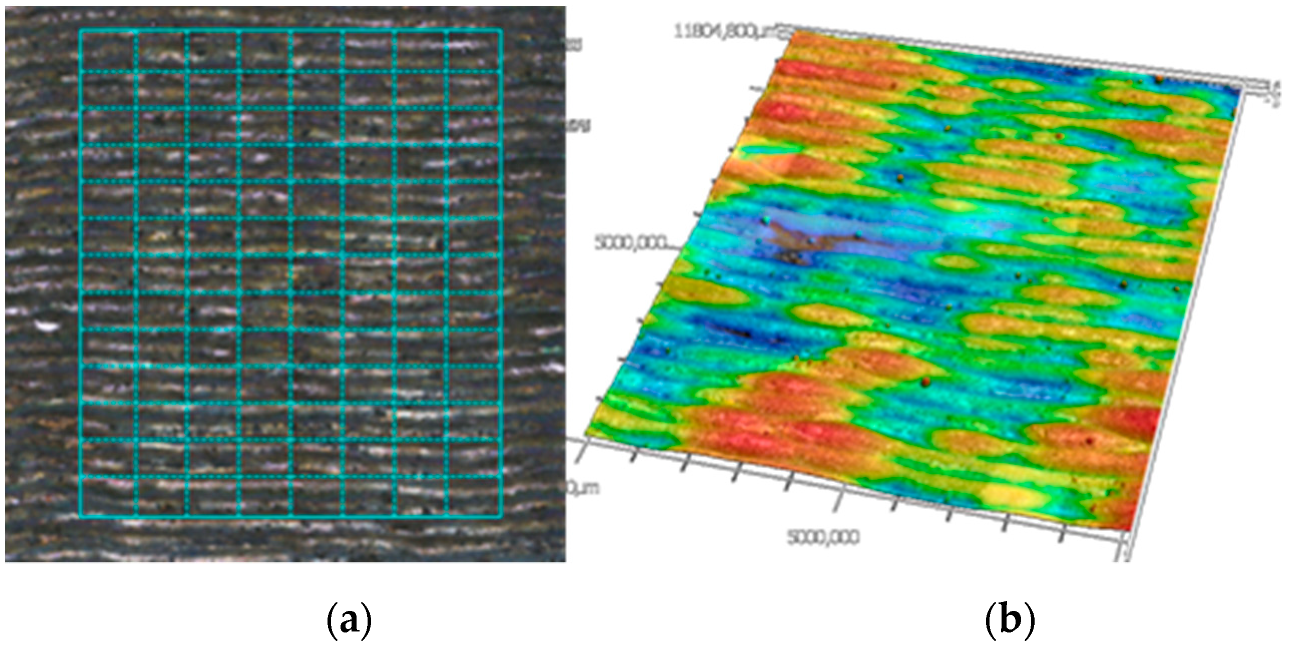
3D scanning with the GOM Atos Core was used for the omnidirectional measurement of the flatness which represents the minimal distance of two planes that include all points of the surface. The Keyence VK-250 combines laser scanning and confocal microscopy and was used for primary areal and profile surface texture measurements. Scans were taken with a magnification of ten and stitched together resulting in a total area of 12 × 10 mm2.
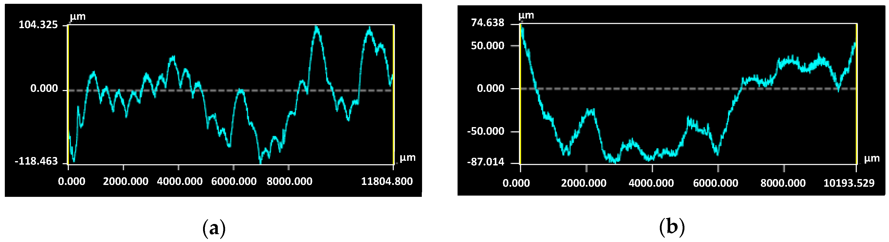
For profile measurements, two directions have been chosen: building direction Z and perpendicular to Z direction X representing the profile along one layer. To increase the accuracy of the measurements, twenty parallel profile lines were evaluated and thus the resulting parameters are averaged values. For areal measurements, a form suppressing filter was used to eliminate the effect of a tilted surface.
The following two profile and areal parameters were measured: the arithmetical mean height S
a/P
a and the maximum height S
z/P
z defined as the sum of the largest peak height value and the largest pit depth value within the defined area/profile [
28].

 ,
, 


