Deformation-Assisted Joining of Sheets to Tubes by Annular Sheet Squeezing


Instituto de Engenharia Mecânica, Instituto Superior Técnico, Universidade de Lisboa, Av. Rovisco Pais, 1049-001 Lisboa, Portugal
*
Author to whom correspondence should be addressed.
Materials 2019, 12(23), 3909; https://doi.org/10.3390/ma12233909
Submission received: 28 October 2019
/
Revised: 24 November 2019
/
Accepted: 25 November 2019
/
Published: 26 November 2019
(This article belongs to the Special Issue Special Issue of the Manufacturing Engineering Society 2019 (SIMES-2019))
Abstract
:This paper is built upon the deformation-assisted joining of sheets to tubes, away from the tube ends, by means of a new process developed by the authors. The process is based on mechanical joining by means of form-fit joints that are obtained by annular squeezing (compression) of the sheet surfaces adjacent to the tubes. The concept is different from the fixing of sheets to tubes by applying direct loading on the tubes, as is currently done in existing deformation-assisted joining solutions. The process is carried out at room temperature and its development is a contribution towards ecological and sustainable manufacturing practices due to savings in material and energy consumption and to easier end-of-life disassembly and recycling when compared to alternative processes based on fastening, riveting, welding and adhesive bonding. The paper is focused on the main process parameters and special emphasis is put on sheet thickness, squeezing depth, and cross-section recess length of the punches. The presentation is supported by experimentation and finite element modelling, and results show that appropriate process parameters should ensure a compromise between the geometry of the mechanical interlocking and the pull-out strength of the new sheet–tube connections.
1. Introduction
In recent years, there has been a growing utilization of deformation-assisted joining processes driven by an increasing demand of assembling lightweight components. Deformation-assisted joining processes are classified into three distinct groups according to their operating principles:
- (i)
- (ii)
- (iii)
Some of the above-mentioned processes have been extensively investigated for joining sheets and tubes made from similar or dissimilar materials. The state-of-the-art reviews by Mori et al. [12] and Groche et al. [13] provide detailed information on the most significant developments and applications of deformation-assisted joining processes to connect sheets and tubes.
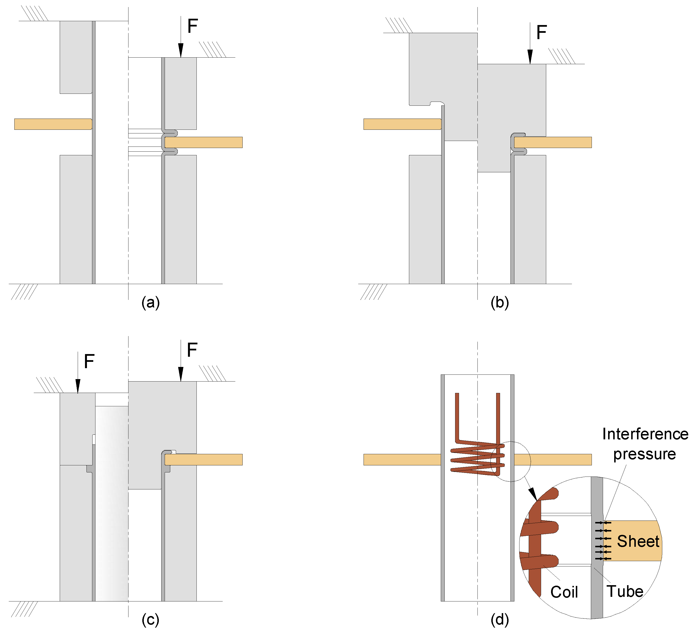
Despite the progresses in sheet-to-sheet and tube-to-tube connections, the joining of sheets-to-tubes is still preferentially accomplished by means of conventional fastening and welding technologies. Little progress has been made in the application of deformation-assisted joining to sheet–tube connections, aside from recent developments involving the utilization of form-fit mechanical joints based on compression beads formed by local buckling [14], on the combination of tube compression beads with flaring [15], and on the combination of partial sheet-bulk compression of tubes with upsetting [16] or flaring [17] (Figure 1a–c).
The utilization of force-fit mechanical joints that exclusively rely on the pressure that remains on the contact interfaces after elastic recovery from mechanical [18], hydraulic [5], or magnetic loading [6] is not a feasible solution for the fixing of sheets to tubes due to the limited contact surfaces provided by the small thickness sheets that are commonly used in the industry (Figure 1d). Similar constraints apply to new developments for the joining of thick blocks (or plates) to tubes by compressing the upper end of a connecting block flange [19,20] because of the need to produce the connecting flange by machining.
Regarding the connection of sheets to tubes, which is the main objective of this paper, it is worth mentioning that all the previously mentioned deformation-assisted joining processes based on mechanical form-fit joints [14,15,16,17] involve multiple operations. This undercuts their advantages in material consumption, energy requirements, and end-of-life recycling with disadvantages related to efficiency and costs that are better ensured by conventional technologies based on fastening, welding, and adhesive bonding. Besides the limitations resulting from existing processes based on mechanical form-fit joints being carried out in multiple operations, there is also the risk of failure by cracking in the compression beads produced by local buckling. This reduces their applicability to tubes with low fracture toughness [21].
All of the above-mentioned problems prompted the authors to develop a new process for fixing sheets to tubes at room temperature that is based on an entirely new mechanical joining concept in which loading is applied on the sheet surface instead of the tube itself [22]. The process is schematically shown in Figure 2, and consists of squeezing (compressing) the annular surface of the sheet adjacent to the tube in order to ensure the material from the sheet flows inwards and is shaped as a form-fit joint with good mechanical interlocking between the sheet and the tube.
The new joining process is performed in a single punch stroke and requires both the sheet and the tube to have some degree of ductility to plastically shape the form-fit joint. The optimum operating conditions require the material of the tube to have a lower elastic modulus than that of the sheet, so that the pressure remains on the contact interface after producing the form-fit joint as a result of the more pronounced elastic recovery of the tube in the direction of the sheet. Otherwise, the resulting form-fit joint may end up slightly loose as in the case of sheet–tube connections made from dissimilar materials (e.g., metals and polymers or composites) with very different elastic modulus. Another requirement of the new proposed joining process is the necessity of the sheet strength being similar or higher to that of the tube to allow for easy shaping of the inner tube bead that is needed to produce the form-fit mechanical joint.
Finally, it is worth mentioning that the new joining process circumvents the previously-mentioned difficulties resulting from the utilization of tubular materials with low fracture toughness.
This paper is focused on the main process parameters of deformation-assisted joining of sheets to tubes by annular sheet squeezing, hereafter designated as ‘mechanical joining of sheets to tubes’. Special emphasis is put on the sheet thickness , squeezing depth , and cross-section recess length of the punches due to their influence on the inner tube bead shape of the form-fit joint and on the quality and performance of the mechanical joint between the sheet and the tube. The presentation includes results from experimentation and finite element modelling, and from destructive pull-out tests that were carried out to determine the maximum force that the new joints can withstand before failing.
2. Materials and Methods
2.1. Materials and Flow Curves
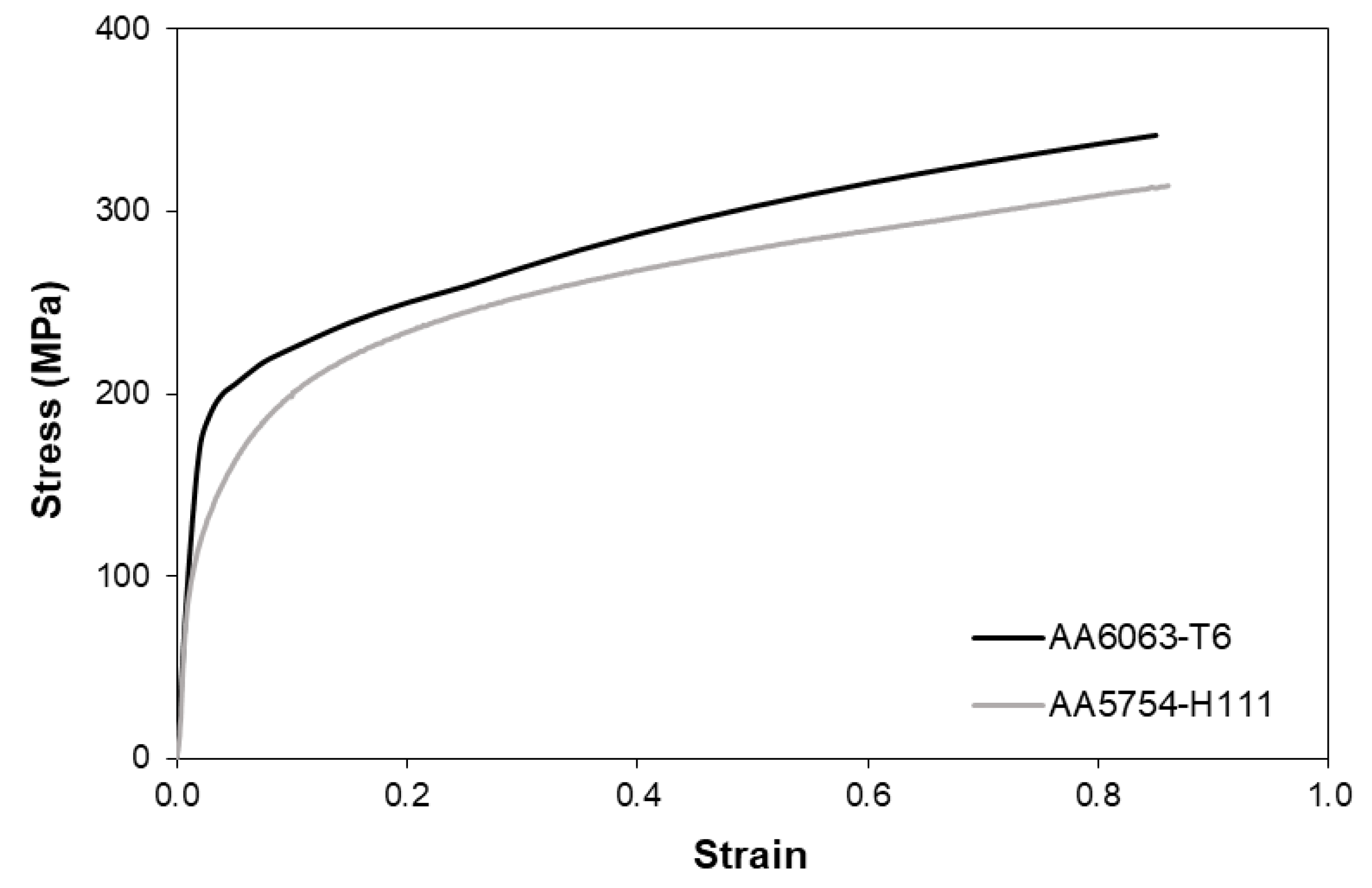
The work on the mechanical joining of sheets to tubes by annular sheet squeezing was carried out in two different aluminum alloys. The sheets were made of aluminum AA5754-H111 with a 5 mm thickness and the tubes were made of aluminum AA6063-T6 with an outer radius of 16 mm and a 1.5 mm wall thickness.
The flow curves of the two materials were obtained by combining tensile and stack compression tests [23] performed in a hydraulic testing machine with a cross-head speed of 5 mm/min. The tensile tests allowed characterization of the stress response of the materials for small values of strain, whereas the stack compression tests were utilized to determine the stress response for larger values of strain, beyond plastic instability in tension, following a procedure similar to that of Silva et al. [4]. The flow curves of the AA5754-H111 sheets and AA6063-T6 tubes are shown in Figure 3.
The reason for using two materials with similar flow curves and nearly identical elasticity moduli (with differences within the range of 68 to 68.9 GPa) was to allow for the study of the performance of the form-fit joints alone and independently of the interfacial pressure, which develops on the sheet–tube contact surface in case of form-fit joints made from materials with a different elasticity modulus.
2.2. Experimental Tests
In their original paper on the mechanical joining of sheets to tubes by annular sheet squeezing [22], the authors put emphasis on the influence of the cross-section recess length of the punch on plastic material flow inside the sheet thickness. The squeezing depth was kept constant and a deformation-zone geometry parameter , defined as the ratio of the sheet thickness to the cross-section recess length , was introduced to characterize material flow and identify the deformation modes associated with acceptable and unacceptable joints.
In a subsequent paper [24], the authors focused on the complementary work plan by analyzing the influence of the squeezing depth and keeping the cross-section recess length of the punch at a fixed value. The investigation allowed the characterization of the physics behind material separation at the cross-section recess corner of the punch and to reach a better understanding of the influence of the squeezing depth on the pull-out destructive strength of the joints.
The work plan giving support to this paper takes the combined influence of and into account. The goal is to understand how changes in both variables at the same time will influence material flow and the overall pull-out performance of the joints so that a procedure can be reached to determine the combination of squeezing depth and cross-section recess length that is capable of ensuring the best form-fit joint for a supplied set of geometries and materials.
Such a procedure has not been addressed in previous papers and is of paramount importance when producing form-fit joints in dissimilar materials in which the strength of the tube is similar or slightly higher than that of the sheet.
The overall methodology utilized in the experimental tests consisted on the following steps:
- The tube and the sheet were first cut to the required sizes;
- A hole with a diameter equal to the outer tube diameter was drilled in the sheet;
- The tube and the sheet were then placed in the tooling system installed in a hydraulic testing machine INSTRON SATEC 1200 kN;
- The hydraulic testing machine moved the punch downwards in order to locally compress the sheet up to a total squeezing depth
- Steps 1 to 4 were repeated several times in order to vary the sheet thickness ts, the cross-section recess length of the punch, and the squeezing depth d according to the values listed in Table 1. All the tests were performed at room temperature;
- After finishing the tests, selected samples were cut along their axial cross-sectional planes in order to analyze their mechanical form-fit joints, to take photographs, and to perform measurements;
- Finally, another set of selected samples was subjected to destructive pull-out tests in order to evaluate the overall performance of the joints.
Table 1 presents a summary of the experiments on mechanical joining together with the major geometrical specifications of the sheets and tubes that were utilized in the investigation. The influence of the sheet thickness was taken into consideration by extending the experimental work to sheets with a smaller thickness ( mm) than the nominal supplied thickness mm.
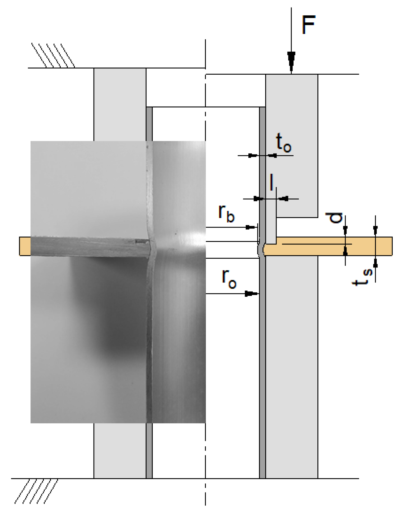
Figure 4 presents a schematic representation of the experimental setup that was utilized to evaluate the performance of the new form-fit joints. The joints were subjected to destructive pull-out tests in which the sheet was detached from the tube, and the objective was the determination of the maximum force F that the joints can withstand before failing.
2.3. Finite Element Modelling
The in-house finite element computer program I-form was utilized to analyze the mechanical joining of sheets to tubes by annular sheet squeezing. The computer program is based on the finite element flow formulation [25], and its implementation follows the extension of the rigid-plastic Markov’s principle [26] of minimum plastic work to include incompressibility and contact between deformable bodies,
In the first term of Functional (1), the symbols and denote the effective stress and the effective strain rate, respectively,
where is the deviatoric stress tensor and is the strain rate tensor.
In the second term, the symbol is the volumetric strain rate, given by
where is the Kronecker delta and is a large positive number utilized to impose incompressibility in volume by means of a penalty factor.
The third term of Functional (1) makes use of the surface tractions and velocities on the surface , whereas the fourth term takes care of the frictional effects along the contact interface between the sheet and tube with the tools. In this work, tools were assumed as rigid bodies, and and denote the friction shear stress and relative sliding velocity of the sheet and tube. The friction shear stress was modelled according to the law of constant friction,
where is the friction factor between the sheets and tubes, taken as 0.1 after checking the predicted forces that best matched the experimental results. The symbol denotes the flow shear stress.
The fifth and sixth terms account for the contact between the sheet and tube modelled as deformable bodies along their contact interfaces defined by means of pairs extracted from the faces of the elements that were utilized in their discretization. The symbols and denote the normal and tangential gap velocities in the contact pairs, which are penalized by large numbers and to avoid penetration. A more detailed look into the numerical implementation of Functional (1) in the finite element computer program I-form can be found in reference [27].
Figure 5 shows in detail the finite element model before and after the sheet is mechanically joined to the tube. The finite element models utilized in the numerical modelling of the process made use of rotational symmetry conditions and required discretization of the longitudinal cross-section of the sheets and tubes by means of approximately 20,000 and 800 quadrilateral elements, respectively. The sheet and the tube were modelled as deformable bodies, whereas the tools were modelled as rigid objects and discretized by means of linear contact-friction elements. Several remeshings were carried out to avoid excessive element distortion during annular sheet squeezing.
3. Results
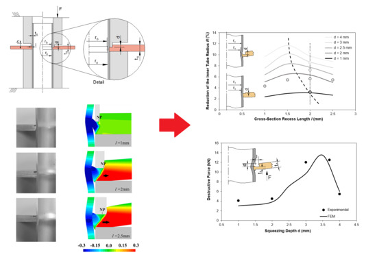
Figure 6 shows the finite element computed reduction of the inner tube radius as a function of the cross-section recess length of the punch for four different values of the squeezing depth . Experimental measurements of for a squeezing depth mm and a cross recess length mm are included to assess the validity and reliability of the finite element estimates.
The first conclusion derived from Figure 6 is that small values of lead to small amounts of material being displaced against the tube, and therefore, to the development of less pronounced inner tube bead geometries of the form-fit joints. In contrast, large values of give rise to large amounts of material being squeezed against the tube and to more pronounced inner tube bead geometries of the form-fit joints. This is graphically shown in the two schemes that are included in Figure 6.
As seen in Figure 6, a typical evolution passes through a peak corresponding to the cross-section recess length that provides the maximum reduction of the inner tube radius for a given squeezing depth . The dashed curve passing through all these peaks defines the correlation between and that maximizes the inner tube bead geometry of the form-fit joints.
To the left of the dashed curve, there is a decrease in the amount of sheet material being squeezed as the cross-section recess length diminishes. This leads to smaller values of and to the development of less pronounced inner tube bead geometries of the form-fit joints. At the limit, there will be no form-fit joint.
Contrary to what one would expect, to the right of the dashed curve, the evolutions should increase were it not for the squeezed sheet material starting to moving outwards instead of inwards.
This last conclusion is confirmed by the computed evolution of the normalized radial velocity , where is the vertical punch velocity, shown in Figure 7b. As seen in case of mm, when the cross-section recess length of the punch increases from mm to mm, there is a shift of the neutral point (NP), corresponding to the transition between inward and outward material flow towards the left corner of the punch, meaning that more squeezed sheet material will start flowing outwards (refer to the black arrows included in Figure 7b).
Another consequence of the squeezed sheet material starting to flow outwards is the occurrence of bending. Bending gives rise to form-fit joints with a lack of perpendicularity between the sheet and the tube, as shown in the bottom experimental and numerically predicted cross-sections that are included in Figure 7a.
4. Discussion
4.1. Pull-Out Destructive Forces
The results obtained in Section 3 showed that both the cross-section recess length and the squeezing depth of the punch play a key role in the geometry of the inner tube bead of the form-fit joints.
One question that naturally arises from Figure 6 is whether the correlation between and that maximizes the inner tube bead geometry of the form-fit joints is capable of ensuring the maximum pull-out forces that the joints can safely withstand before failing.
To answer this question, the authors took the form-fit joint with mm and mm lying close to the correlation line that maximizes the inner tube bead geometry and compared its pull-out destructive force with those obtained for other joints that were obtained by varying along the dotted vertical line of Figure 6.
The results from experimental tests and numerical simulations are shown in Figure 8 and allow to conclude that the maximum pull-out destructive force is not obtained for the process operating conditions that maximize the inner tube bead geometry of the form-fit joints.
Whilst at a first glance, this result may seem easy to explain because large values of should give rise to larger inner tube beads of the form-fit joints, there is an additional phenomenon that also needs to be considered. Otherwise, it is not possible to fully understand the experimental and numerical results included in Figure 8, because the increase of the pull-out force with is only monotonic up to a peak, after which the force drops sharply.
The additional phenomenon that needs to be considered for understanding the evolution of the pull-out force with is the failure mechanism. In particular, the change in mechanism when the active sheet thickness left below the cross-section recess length of the punch (refer to the inset included in Figure 8) becomes very small.
Taking, for example, the pull-out force vs. displacement evolutions for the form-fit joints with mm and mm retrieved from Figure 8, it is easy to observe two totally different separation mechanisms (Figure 9a). One mechanism, leading to higher forces, is similar to tube extrusion while the other mechanism, leading to lower forces and a sharp drop at the end, is related to shearing.
In case of the first mechanism, observed in the pull-out test of the form-fit joint with mm, the sheet acts as a floating die and the tube is forced to plastically deform in order to reduce its inner radius from to . The maximum pull-out force attained in the destructive test is approximately equal to 12 kN.
The second mechanism, observed in the pull-out test of the form-fit joint with mm, is typical of shearing along the small active sheet thickness that was left below the cross-section recess length of the punch. The maximum pull-out force associated to this mechanism is smaller than that of tube extrusion.
The photographs included in Figure 9b illustrate the differences between the two above-mentioned failure mechanisms. The conclusion to be taken from these tests is that the design of a joint to be produced by a punch having a cross-section length mm must consider a squeezing depth mm to ensure high pull-out destructive forces.
In connection to this, it is worth mentioning that the concept of maximum pull-out force utilized by the authors refers to the force that prevents collapse by avoiding detachment of the two components and not to the force that is needed to produce the first relative movement between the sheet and the tube.
4.2. Sheet Thickness
The other question one may have about the mechanical joining of sheets to tubes by annular sheet squeezing is whether the process works for smaller sheet thicknesses than that utilized in the previous sections. To answer this question authors decided to produce sheet–tube joints using the same tube geometry but reducing the sheet thickness from mm to mm. The photograph included in Figure 10a shows that the process is still feasible for sheets with smaller thicknesses.
In view of the above, it is interesting for the readers to know which values of the cross-section recess length and squeezing depth of the punch were utilized to produce the form-fit joint with a sheet thickness mm. For this purpose, it is important to observe in Figure 8 that the maximum pull-out force of a form-fit joint produced with a punch having a cross-section recess length mm is obtained for a squeezing depth mm. Larger values of , leading to active sheet thicknesses mm, provide smaller pull-out forces because the failure mechanism changes from extrusion to shearing.
So, in order to use the same punch ( mm) for comparison purposes, and prevent failure by shearing in case mm, it was decided to use a squeezing depth mm for obtaining the form-fit joint with a sheet thickness mm.
Figure 10b shows a detail of the computed finite element cross sections for the form-fit joints obtained for the two different sheet thicknesses. As seen, the magnitude of bending is significant in both cases, namely in the sheet with smaller thickness due to its lower stiffness. However, the phenomenon can be easily avoided by diminishing the gap between the cross-section recess length and the remaining flat surface of the punch so that the total amount of bending is limited.
5. Conclusions
Deformation-assisted joining of sheets to tubes by annular sheet squeezing is based on mechanical joining by means of form-fit joints. The amount of sheet material to be squeezed and the final shape and volume of the inner tube beads of the form-fit joints is controlled by the cross-section recess length of the punch, the squeezing depth and by the geometry of the punch and sheet, namely the sheet thickness .
By varying these parameters, it is possible to change the plastic flow of the squeezed sheet material from a predominantly inward into a combination of inward and outward. In particular, it is possible to define a combination of parameters capable of ensuring maximum shapes and volumes of the form-fit joints for given values of or . However, the maximum shapes and volumes of the form-fit joints do not necessarily provide the maximum pull-out destructive forces because there is a minimum active sheet thickness below which the failure mechanism changes from extrusion to shearing and the forces drop significantly.
In connection to this, it is also shown that the new mechanical joining process is not limited to thick sheets because what needs to be fulfilled is a combination of parameters capable of ensuring a sound mechanical joint for values of the active sheet thickness above the critical threshold of failure by shearing.
Author Contributions
L.M.A. and R.M.A. designed and fabricated the tools. L.M.A., R.M.A. and F.L.R.S. performed the experimental and numerical simulation work. L.M.A and P.A.F.M. developed the finite element computer program and analyzed the results. P.A.F.M. supervised the overall research work and wrote the article with the collaboration of all the other authors.
Funding
This research was funded by Fundação para a Ciência e a Tecnologia of Portugal under LAETA - UID/EMS/50022/2019 and PDTC/EMS-TEC/0626/2014.
Acknowledgments
The authors would like to acknowledge the support provided by IDMEC and Fundação para a Ciência e a Tecnologia of Portugal.
Conflicts of Interest
The authors declare no conflict of interest. The funders had no role in the design of the study; in the collection, analyses, or interpretation of data; in the writing of the manuscript, or in the decision to publish the results.
References
- Chen, C.; Zhao, S.; Han, X.; Zhao, X.; Ishida, T. Experimental investigation on the joining of aluminum alloy sheets using improved clinching process. Materials 2017, 10, 887. [Google Scholar] [CrossRef] [PubMed]
- Chen, C.; Zhao, S.; Han, X.; Wang, Y.; Zhao, X. Investigation of flat clinching process combined with material forming technology for aluminum alloy. Materials 2017, 10, 1433. [Google Scholar] [CrossRef] [PubMed]
- Jäckel, M.; Grimm, T.; Niegsch, R.; Drossel, W.G. Overview of current challenges in self-pierce riveting of lightweight materials. Proceedings 2018, 3, 384. [Google Scholar] [CrossRef]
- Silva, D.F.M.; Silva, C.M.A.; Bragança, I.M.F.; Nielsen, C.V.; Alves, L.M.; Martins, P.A.F. On the performance of thin-walled crash boxes joined by forming. Materials 2018, 11, 1118. [Google Scholar] [CrossRef] [PubMed]
- Marre, M.; Rautenberg, J.; Tekkaya, A.E.; Zabel, A.; Biermann, D.; Wojciechowski, J.; Przybylski, W. An experimental study on the groove design for joints produced by hydraulic expansion considering axial or torque load. Mater. Manuf. Process. 2012, 27, 545–555. [Google Scholar] [CrossRef]
- Psyk, V.; Risch, D.; Kinsey, B.L.; Tekkaya, A.E.; Kleiner, M. Electromagnetic forming-A review. J. Mater. Process. Technol. 2011, 211, 787–829. [Google Scholar] [CrossRef]
- Serio, L.M.; Palumbo, D.; Filippis, L.A.C.D.; Galietti, U.; Ludovico, A.D. Effect of friction stir process parameters on the mechanical and thermal behavior of 5754-H111 aluminum plates. Materials 2016, 9, 122. [Google Scholar] [CrossRef]
- Zhang, B.; Chen, X.; Pan, K.; Wang, J. Multi-objective optimization of friction stir spot-welded parameters on aluminum alloy sheets based on automotive joint loads. Metals 2019, 9, 520. [Google Scholar] [CrossRef]
- Mahmood, Y.; Dai, K.; Chen, P.; Zhou, Q.; Bhatti, A.A.; Arab, A. Experimental and numerical study on microstructure and mechanical properties of Ti-6Al-4V/Al-1060 Explosive Welding. Metals 2019, 9, 1189. [Google Scholar] [CrossRef]
- Cortés, V.H.V.; Guerrero, G.A.; Granados, I.M.; Hernández, V.H.B.; Zepeda, C.M. Effect of retained austenite and non-metallic inclusions on the mechanical properties of resistance spot welding nuggets of low-alloy TRIP steels. Metals 2019, 9, 1064. [Google Scholar] [CrossRef]
- Lim, Y.C.; Park, H.; Jang, J.; McMurray, J.W.; Lokitz, B.S.; Keum, J.K.; Wu, Z.; Feng, Z. Dissimilar materials joining of carbon fiber polymer to dual phase 980 by friction bit joining, adhesive bonding, and weldbonding. Metals 2018, 8, 865. [Google Scholar] [CrossRef]
- Mori, K.; Bay, N.; Fratini, L.; Micari, F.; Tekkaya, A.E. Joining by plastic deformation. CIRP Ann. Manuf. Technol. 2013, 62, 673–694. [Google Scholar] [CrossRef]
- Groche, P.; Wohletz, S.; Brenneis, M.; Pabst, C.; Resch, F. Joining by forming-A review on joint mechanisms, applications and future trends. J. Mater. Process. Technol. 2014, 214, 1972–1994. [Google Scholar] [CrossRef]
- Alves, L.M.; Dias, E.J.; Martins, P.A.F. Joining sheet panels to thin-walled tubular profiles by tube end forming. J. Clean. Prod. 2011, 19, 712–719. [Google Scholar] [CrossRef]
- Alves, L.M.; Martins, P.A.F. Single-stroke mechanical joining of sheet panels to tubular profiles. J. Manuf. Process. 2013, 15, 151–157. [Google Scholar] [CrossRef]
- Alves, L.M.; Afonso, R.M.; Silva, C.M.A.; Martins, P.A.F. Joining tubes to sheets by boss forming and upsetting. J. Mater. Process. Technol. 2018, 252, 773–781. [Google Scholar] [CrossRef]
- Alves, L.M.; Afonso, R.M.; Silva, C.M.A.; Martins, P.A.F. Joining sandwich composite panels to tubes. J. Mater. Des. Appl. 2019, 233, 1472–1481. [Google Scholar] [CrossRef]
- Hao, J.W.; Pan, H.L.; Tang, S.H. Research of elastomeric expansion for tube-to-tubesheet joint. In Proceedings of the ASME Pressure Vessels and Piping Division Conference, Vancouver, BC, Canada, 23–27 July 2006; pp. 1–5. [Google Scholar]
- Wrobel, N.; Rejek, M.; Krolczyk, G.; Hloch, S. Testing of Tight Crimped Joint Made on a Prototype Stand; Advances in Manufacturing, Lecture Notes in Mechanical Engineering; Springer: Cham, Switzerland, 2017; pp. 497–507. ISBN 978-3-319-68619-6. [Google Scholar]
- Rejek, M.; Wróbel, N.; Królczyk, J.; Królczyk, G. Designing and testing cold-formed rounded connections made on a prototype station. Materials 2019, 12, 1061. [Google Scholar] [CrossRef]
- Sizova, I.; Sviridov, A.; Bambach, M. Avoiding crack nucleation and propagation during upset bulging of tubes. Int. J. Mater. Form. 2017, 10, 443–451. [Google Scholar] [CrossRef]
- Alves, L.M.; Silva, F.L.R.; Afonso, R.M.; Martins, P.A.F. Joining sheets to tubes by annular sheet squeezing. Int. J. Mach. Tools Manuf. 2019, 143, 16–22. [Google Scholar] [CrossRef]
- Alves, L.M.; Nielsen, C.V.; Martins, P.A.F. Revisiting the fundamentals and capabilities of the stack compression test. Exp. Mech. 2011, 51, 1565–1572. [Google Scholar] [CrossRef]
- Alves, L.M.; Silva, F.L.R.; Afonso, R.M.; Martins, P.A.F. A new joining by forming process for fixing sheets to tubes. Int. J. Adv. Manuf. Technol. 2019, 104, 3199–3207. [Google Scholar] [CrossRef]
- Tekkaya, A.E.; Martins, P.A.F. Accuracy, reliability and validity of finite element analysis in metal forming: A user’s perspective. Eng. Comput. 2009, 26, 1026–1055. [Google Scholar] [CrossRef]
- Markov, A.A. On variational principles in theory of plasticity. Prikl. Mat. Mek. 1947, II, 339–350. [Google Scholar]
- Nielsen, C.V.; Zhang, W.; Alves, L.M.; Bay, N.; Martins, P.A.F. Modelling of Thermo-Electro-Mechanical Manufacturing Processes with Applications in Metal Forming and Resistance Welding; Springer: London, UK, 2013; ISBN 978-1-4471-4643-8. [Google Scholar]
Figure 1.
Deformation-assisted joining of sheets to tubes by mechanical joining. (a) Form-fit joints produced by tube compression beads formed by local buckling. (b) Form-fit joints produced by a combination of tube compression beads and flaring. (c) Form-fit joints produced by a combination of partial sheet-bulk compression of tubes and flaring. (d) Force-fit joints produced by the pressure that remains after elastic recovery from magnetic loading.

Figure 2.
A representation of the deformation-assisted joining of sheets to tubes by annular sheet squeezing at the open and closed positions [22]. A photograph of a longitudinal cross section of a test specimen is enclosed.
Figure 2.
A representation of the deformation-assisted joining of sheets to tubes by annular sheet squeezing at the open and closed positions [22]. A photograph of a longitudinal cross section of a test specimen is enclosed.

Figure 3.
Flow curves of the two aluminum alloys utilized in the experiments.

Figure 4.
A representation of the experimental pull-out destructive setup before (left) and during testing (right).
Figure 4.
A representation of the experimental pull-out destructive setup before (left) and during testing (right).

Figure 5.
Element meshes before and after fixing the sheet to the tube using mechanical joining by annular sheet squeezing ( mm and mm and mm).
Figure 5.
Element meshes before and after fixing the sheet to the tube using mechanical joining by annular sheet squeezing ( mm and mm and mm).

Figure 6.
Reduction of the inner tube radius as a function of the cross-section recess length of the punch for different values of the squeezing depth .
Figure 6.
Reduction of the inner tube radius as a function of the cross-section recess length of the punch for different values of the squeezing depth .

Figure 7.
Influence of the cross-section recess length of the punch on the form-fit joints for a squeezing depth mm. (a) Experimental cross-sections of the form-fit joints; (b) Finite element predicted cross-sections of the form-fit joints with the distribution of normalized radial velocity .
Figure 7.
Influence of the cross-section recess length of the punch on the form-fit joints for a squeezing depth mm. (a) Experimental cross-sections of the form-fit joints; (b) Finite element predicted cross-sections of the form-fit joints with the distribution of normalized radial velocity .

Figure 8.
Influence of the squeezing depth on the pull-out destructive force of sheet–tube connections obtained with a punch having a cross-section recess length mm.
Figure 8.
Influence of the squeezing depth on the pull-out destructive force of sheet–tube connections obtained with a punch having a cross-section recess length mm.

Figure 9.
Pull-out tests. (a) Experimental evolution of the force with displacement for destructive pull-out tests performed in two different form-fit joints that were produced with a punch having a cross-section recess length mm. (b) Photographs of the two different tests specimens after failure by extrusion (left) and shearing (right).

Figure 10.
Mechanical joining of sheets to tubes by annular sheet squeezing using a punch with a cross section recess length mm and two different thicknesses mm and mm. (a) Photographs of sheets and tubes after being joined. (b) Finite element predicted cross section at the end of stroke for the two test cases shown in (a) using a squeezing depth mm (left) and mm (right).


Table 1.
The experiments on the mechanical joining of sheets to tubes by annular sheet squeezing. Notation is in accordance with Figure 2.
Table 1.
The experiments on the mechanical joining of sheets to tubes by annular sheet squeezing. Notation is in accordance with Figure 2.
| r0 (mm) | t0 (mm) | ts (mm) | l (mm) | d (mm) |
|---|---|---|---|---|
| 14.5 | 1.5 | 2.5, 5 | 0.5–2.5 | 1.0–4.0 |
© 2019 by the authors. Licensee MDPI, Basel, Switzerland. This article is an open access article distributed under the terms and conditions of the Creative Commons Attribution (CC BY) license (http://creativecommons.org/licenses/by/4.0/).
Share and Cite
MDPI and ACS Style
Alves, L.M.; Afonso, R.M.; Silva, F.L.R.; Martins, P.A.F. Deformation-Assisted Joining of Sheets to Tubes by Annular Sheet Squeezing. Materials 2019, 12, 3909. https://doi.org/10.3390/ma12233909
AMA Style
Alves LM, Afonso RM, Silva FLR, Martins PAF. Deformation-Assisted Joining of Sheets to Tubes by Annular Sheet Squeezing. Materials. 2019; 12(23):3909. https://doi.org/10.3390/ma12233909
Chicago/Turabian StyleAlves, Luis M., Rafael M. Afonso, Frederico L.R. Silva, and Paulo A.F. Martins. 2019. "Deformation-Assisted Joining of Sheets to Tubes by Annular Sheet Squeezing" Materials 12, no. 23: 3909. https://doi.org/10.3390/ma12233909
Note that from the first issue of 2016, this journal uses article numbers instead of page numbers. See further details here.