Key Role of Precursor Nature in Phase Composition of Supported Molybdenum Carbides and Nitrides


Unipetrol Centre for Research and Education, a.s, Areál Chempark 2838, Záluží 1, 436 70 Litvínov, Czech Republic
*
Author to whom correspondence should be addressed.
Materials 2019, 12(3), 415; https://doi.org/10.3390/ma12030415
Submission received: 18 December 2018
/
Revised: 23 January 2019
/
Accepted: 24 January 2019
/
Published: 29 January 2019
(This article belongs to the Special Issue Heterogeneous Catalysts Synthesis and Characterization)
Abstract
:In this work, we studied the effect of molybdenum precursors and the synthesis conditions on the final phase composition of bulk and supported molybdenum carbides and nitrides. Ammonium heptamolybdate, its mixture with hexamethylenetetramine, and their complex were used as the precursors at different temperatures. It was investigated that the synthesis of the target molybdenum nitrides strongly depended on the structure of the precursor and temperature conditions, while the synthesis of carbide samples always led to the target phase composition. Unlike the carbide samples, where the α-Mo2C phase was predominant, the mixture of β-Mo2N, MoO2 with a small amount of metal molybdenum was generally formed during the nitridation. All supported samples showed a very good dispersion of the carbide or nitride phases.
1. Introduction
There are three types of bonding between the transition metal and carbon or nitrogen atoms: metal bonding (metal-metal), covalent bonding (metal and non-metal), and ionic bonding (charge between metal and non-metal) [1]. The special crystal structure of transition metal carbides and nitrides is created by inserting carbon or nitrogen into the metal–metal bond is what makes its distance longer than the original. This special bond has exclusive electronic properties, which provide catalytic activity similar to the platinum group metals (Pt, Pd, Ru, etc.) in various reactions [2]. Molybdenum carbides exist in three basic forms: a face-centered cubic (fcc, α-MoC1-x), a hexagonal closed packed (hcp, β-Mo2C), and a simple hexagonal (hex, MoC) structure, while molybdenum nitrides mainly have a cubic structure (fcc, γ-Mo2N) [3].
Molybdenum carbides are widely used as catalysts due to their activity in many reactions, particularly in the water gas shift reaction, deoxygenation, denitrification, desulfurization, oxidation, partial oxidation, hydrotreating (HDS, HDO, HDN), dehydrogenation, isomerization, hydrogenolysis, hydrodemetallization, and methane reforming [4]. Molybdenum nitrides possess a series of unique and superior catalytic properties for HDS, HDO, HDN [4,5], and electrochemical catalysis [6,7]. Possible difficulties in the application of these types of catalysts that may appear are most often related to obtaining those materials with high specific surface areas (usually less than 10 m2/g) or high porosity. However, these parameters may be varied by changing of synthesis conditions.
High surface area Mo2N and Mo2C are synthesized by various methods [8,9]: (a) Direct reaction between metal and non-metal; (b) reaction of metal oxide in the presence of solid carbon; (c) reaction of metal or compounds with gas phase reagent; (d) temperature-programmed methods; (e) reaction between metal oxide vapor and solid carbon under vacuum; (f) pyrolysis of an organometallic complex under H2, and other methods where thin carbide films are obtained by chemical vapor deposition [10], plasma method, or electrochemical reduction [11,12,13].
The oldest method for synthesis of molybdenum carbides is the direct reaction of metals or metal oxides with elemental carbon in a vacuum or reducing atmosphere of Н2 at 1200–2000 °C, and a self-propagating high-temperature synthesis. The indicated methods produce only bulk metal carbides with low specific surface areas [14].
Using carbon black (CB) as a carburizing agent is a completely new technique for molybdenum carbide preparation. In this synthesis, a mixture of ammonium heptamolybdate (AHM) solution with a CB suspension in acetone is heated up to 350 °C in the air. Then, the obtained МoО3/СВ precursor is carbidized in a gas mixture of СН4/Н2 [15,16,17]. Recent publications reported an application of organic compounds (ethylene glycol, glucose, sucrose, polymers) as a source of carbon [18,19,20,21]. The organic material is dissolved in water and mixed with molybdic acid or AHM to obtain cubic molybdenum carbides with small crystal domain sizes at a high temperature. In the past decade, a synthesis of metal carbides with the use of mechanical activation was also published [22,23,24,25]. For the synthesis of molybdenum carbides using mechanical activation, CB was impregnated with an aqueous solution of AHM by the incipient wetness method. Synthesized materials showed a good mechanical resistance and relatively high specific surface area (about 125 m2/g).
Preparation of molybdenum nitrides is based mainly on ammonia reduction of molybdenum-containing precursors. Thereby, a high surface area Mo2N (116 m2/g) was prepared through nitridation of MgMoO4 in a flow of N2/H2 gas mixture at 800 °C [26]. However, the general method for synthesis of molybdenum carbides and nitrides is temperature-programmed reduction (TPR), where carburization/nitridation is carried out by a reaction between molybdenum oxide (MoO3 or MoO2) and a gas mixture, such as H2 with carbon- (CH4, C2H6, C3H8, toluene, etc.) or nitrogen-containing gases (NH3, N2).
Different synthesis conditions can also change molybdenum structures, as in the case of (i) a hexagonal closed packed form of molybdenum carbide (hcp; β-Mo2C) using typical temperature ramps [27,28,29,30], (ii) cubic molybdenum carbide phases (fcc; α-MoC1-x) through a special preparation and lower temperatures [31,32,33], or (iii) a cubic molybdenum nitride phase (γ-Mo2N) [9,26]. These methods allow produce not only metal carbides and nitrides as powders or particles, but also supported species [34,35,36] with a high specific surface area. Molybdenum carbides with a high specific surface area are usually synthesized using AHM as a precursor [37]. AHM is dissolved in water and supplemented with HCl to precipitate molybdic acid, which is then dried and held in hydrogen flowing at a high temperature (1500 °C). By this method, very well crystallized and phase pure catalysts characterized by a small specific surface area are produced. Enlargement of the surface area can be obtained by a single-step carbidization of the precursor (AHM or MoO3). When a mixture of CH4/H2 is used as the reaction gas and temperature-programmed heating is up to 500–900 °C for 3 to 6 h [15,38,39,40,41], a hexagonal phase of molybdenum carbide is formed from AHM, while oxides can be transformed into other carbide structures using toluene as the carburizing agent [30,31,42]. The selected ramps and temperatures allow the formation of the cubic phase instead of hexagonal at low temperatures, without the use of any structure stabilizing agents.
In a number of studies, molybdenum nitride and carbide have been prepared by a thermal treatment of single-source precursors. It is a simple and effective method to obtain Mo2C or Mo2N using only hexamethylenetetramine (HMT) as a reducing agent and a carbon or nitrogen source [8,43,44,45,46]. Afanasiev [43] studied the thermal decomposition of a precursor synthesized by reacting HMT with AHM. The resultant HMT-AHM precursor complex [(HMT)2(NH4)4 Mo7O24•2H2O] was decomposed under an argon atmosphere in the temperature range 550–800 °C. Using this method, crystalline Mo2N was synthesized at the temperature higher than 650 °C, while Wang et al. [45] obtained β-Mo2C by mixing HMT with HMT-AHM at the 7:1 molar ratio and at 700 °C in an argon atmosphere.
The main purpose of this study is to gain an understanding of the influence of various preparation methods of a precursor on its final physical, chemical, and textural characteristics. Wang et al. [44] have already presented two basic preparation methods. In the first, authors followed the method reported by Afanasiev [43] and obtained Mo2C, while in the second, they used mechanically mixed AHM and HMT with a molar ratio of 1:4 with obtaining metallic Mo and MoO2. The researchers also described an impact of different parameters in hydrogen thermal treatment preparation of HMT and AHM, namely, AHM:HMT molar ratios, temperature, or heating rates [44]. They reported that pure Mo2C was obtained when the molar ratio of precursors AHM and HMT reached 1:4, and nitride, carbide, and carbonitride composite materials were obtained when the molar ratio was 1:2. They showed that Mo2N became a major product phase at a lower temperature (500 °C), and for Mo2C a higher temperature (650 °C) was needed.
2. Materials and Methods
2.1. Materials
Analytical grade ammonium heptamolybdate (AHM), hexamethylenetetramine (HMT), and ammonia solution (25 wt%) were supplied by Lach-Ner s.r.o. (Neratovice, Czech Republic). The γ-Al2O3 spheres (diameter 2.5 mm) were purchased from Sasol (Hamburg, Germany), and extrudates of zeolite Beta, TiO2, and ZrO2 were purchased from Euro Support Manufacturing Czechia, s.r.o. (Litvínov, Czech Republic). Mesoporous silica SBA-15 (powder) and pellets of alkali-activated zeolite foam (AZF) with diameter 5 mm were synthesized in the laboratory.
2.2. Preparation of Precursors
Based on the method reported by Afanasiev [43], the initial HMT-AHM precursor complex was synthesized using 50 g of AHM and 86 g of HMT dissolved in 300 mL and 400 mL of distilled water, respectively. The solutions were mixed out together and left for 48 h at 3 °C. The sedimented crystals were separated using a paper filter, rinsed with demineralized water, and dried at room temperature for 3 days. The resulted material was named HMT-AHM 7.5×. The samples of HMT-AHM 5× and HMT-AHM 10× with lesser and greater amounts of HMT, correspondingly, were synthesized with the same method.
Mechanically mixed samples of the HMT+AHM (2:1) and HMT+AHM (8:1) precursors were prepared by grinding in a mortar and pestle for 10 min of HMT with AHM in the corresponding molar ratios 2:1 and 8:1. HMT+AHM-S (1:1) and HMT+AHM-S (2:1) precursors with molar ratios 1:1 and 2:1 were synthesized by evaporation of the ammonia solution of HMT with AHM. MoO3 was prepared by calcination of AHM at 450 °C for 6 h.
Precursors for the supported samples were prepared by incipient wetness impregnation of the HMT-AHM 7.5× ammonia solution on the supports Al2O3, TiO2, ZrO2, SBA, BEA, and AZF. Al2O3, impregnated with HMT+AHM-S (2:1), was signed as Al2O3#. To obtain a high content of molybdenum nitride or carbide phase, the impregnation was performed with a saturated solution. The impregnated support from the same batch was used for the carbide and nitride synthesis. In the case of the AZF support after drying at 120 °C for 6 h, the impregnation was repeated once more.
2.3. Synthesis of Molybdenum Carbides and Nitrides
The synthesis of the final nitrides and carbides was carried out in a vertical quartz tubular reactor (UniCRE, Litvínov, Czech Republic) with an internal diameter of 27 mm and length of 1 m (Figure 1), heated to the working temperature by a triple-zone electric oven (CLASIC CZ, spol. s.r.o., Řevnice, Czech Republic) that was regulated by a PID (proportional–integral–derivative) controller. Each precursor or the impregnated support was placed in a fritted quartz cuvette and placed in the center of the reactor. Further processing of the precursors was done in several steps:
- Heating (10 °C/min) of the precursor in the N2 flow (75 cm3/min) at 200 °C for 12 h;
- Heating to the desired temperature (of 10 °C/min) in a working gas flow (75 cm3/min). A mixture of 20 vol% H2 in N2 was used to prepare nitride samples and a mixture of 20 vol% CH4 in H2 for the carbide preparation. After reaching the desired temperature, the reaction was run for 3 h;
- Cooling to the room temperature in the working gas flow (75 cm3/min);
- Flushing the reactor with nitrogen (400 cm3/min) for 30 min;
- Passivation in 1 vol% O2 in Ar (75 cm3/min) for 2 h.
2.4. Characterisation
The chemical composition of the supported samples was determined by X-ray fluorescence analysis (XRF) of powder materials using S8 Tiger (Bruker AXS GmbH, Karlsruhe, Germany) with the Rh cathode. The results were interpreted using the Spectra plus software. The non-supported samples were analyzed by the ICP method using ICP-EOS Agilent 725 (Agilent Technologies Inc., Santa Clara, CA, United States). The carbon and nitrogen content was determined by the elemental analysis of the catalyst powder using Flash2000 Elemental Analyzer (Thermo Fisher Scientific S.p.A., Milan, Italy).
The crystallography of all synthesized material catalysts in powder form was analyzed by X-ray diffraction (XRD) analysis using D8 Advance ECO (Bruker AXS GmbH, Karlsruhe, Germany), applying CuKα radiation (λ = 1.5406 Å) with a resolution of 0.02° and a period of 0.5 s. The patterns were collected in the 2 theta range of 5–70° and evaluated by using the DIFFRAC.EVA software (Bruker AXS GmbH, Karlsruhe, Germany) with the Powder Diffraction File database (PDF 4+ 2018, International Centre for Diffraction Data).
The textural properties of the samples were determined by N2 physisorption and mercury porosimetry. The specific surface area (BET) was measured by N2 adsorption/desorption at 196 °C by using Autosorb iQ (Quantachrome Instruments, Boynton Beach, FL, United States). All the samples were dried under vacuum before the analysis in a glass-cell at 200 °C for 16 h.
The visual appearance was studied by scanning electron microscope (SEM) JSM-7500F (JEOL Ltd., Tokyo, Japan) with a cold cathode-field emission SEM (parameters of measurements: 1 kV, GB high mode). Additional images were obtained by using an optical microscope Jenavert (Carl Zeiss Microscopy GmbH, Jena, Germany) equipped with a Canon EOS 1200D camera (CMOS chip 18 Mpx, Canon, Taiwan). Images with different focusing were folded by the QuickPHOTO CAMERA software (PROMICRA, Prague, Czech Republic).
Physical properties and stability of the precursors and samples were studied by thermogravimetric analysis (TGA) using TGA Discovery series (TA Instruments, New Castle, DE, United States) operating in the temperature range of 40–900 °C (heating 10 °C/min) in the nitrogen flow (20 mL/min, Linde 5.0). A Quadrupole mass detector OmniStar GSD320 (Pfeiffer Vacuum GmbH, Wien, Austria) was used for detection of fragments in SCAN mode with 1450 V voltage of the electron multiplier. Thermal behavior of the samples was analyzed by differential scanning calorimetry (DSC) using Q2000 (TA Instruments, New Castle, DE, United States). Approximately 5–10 mg of a sample was placed into Tzero pierced aluminum pans. An initial temperature was equilibrated at 0 °C, then the samples were cooled down to −50 °C at a rate of 10 °C/min and held for 1 min. After this, the samples were heated up to 450 °C (10 °C/min).
3. Results and Discussion
3.1. Precursors
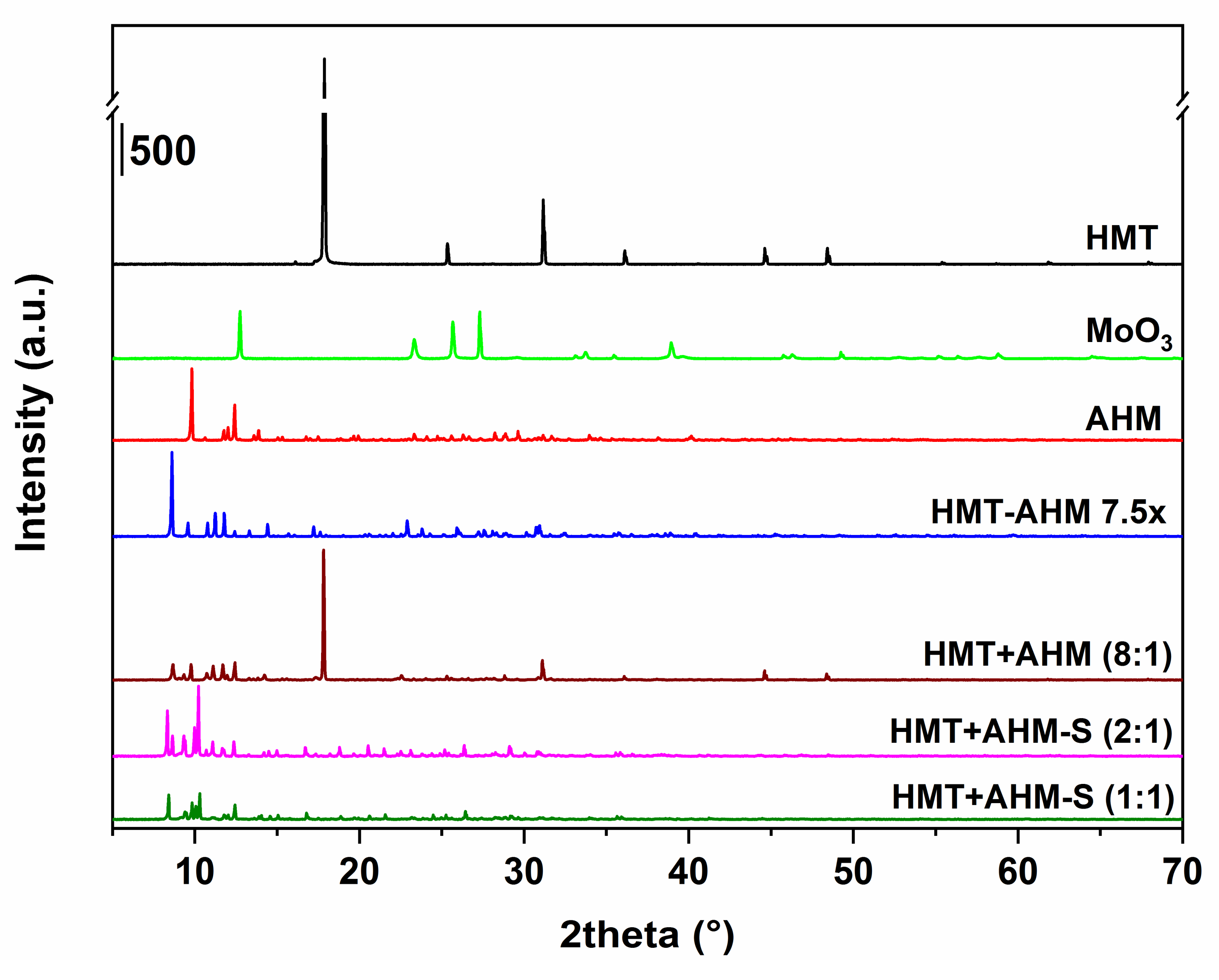
Initially, before the synthesis, all of the precursors were characterized by several analytical methods. As seen from Figure 2, X-ray patterns of the precursor structures differ. In the sample HMT+AHM-M (8:1) produced by mechanical mixing of HMT and AHM, the presence of diffraction lines appropriated to AHM and HMT was observed. However, the line corresponding to the formation of the HMT-AHM complex was also present in the sample.
The precursor complexes, synthesized using HMT+AHM-S, were similar, but not completely the same to those reported by Afanasiev. The MoO3 sample had typical diffraction patterns corresponding to molybdenum trioxide (molybdite).
The influence of the HMT excess on the HMT-AHM complex prepared by the Afanasiev method was investigated by varying the molar ratio of HMT:AHM in the sequence of 15:1 (sample HMT-AHM 7.5×), 10:1, and 20:1 (samples HMT-AHM 5× and 10×). The TGA results (Figure 3) show that the forming complexes were absolutely identical. Their similarity was confirmed by the same decomposition in terms of mass depletion of the final residues and decomposition rates at the corresponding temperatures.
Decomposition of other precursors differed from the HMT-AHM 7.5× sample. Thus, in the case of HMT+AHM-M (2:1) and HMT+AHM-M (8:1), a conspicuous signal at 200 °C inherent to HMT decomposition was observed. The crystallization of the HMT and AHM ammonia solution with a molar ratio of 1:1 in the sample HMT+AHM-S (1:1) led to the formation of large transparent crystals that decomposed differently than when only tiny crystals were formed in the sample HMT+AHM-S (2:1). In spite of the fact that the TGA curves of the latter and HMT-AHM 7.5× went through the same trajectory and were very similar, a slight difference in their structures was noticeable.
TGA decompositions of AHM and HMT-AHM were determined using a mass spectrometer. Using the literature data [47,48], it was possible to determine the individual decomposition steps. It was found that thermal destruction at temperatures from 100 to 190 °C resulted in a simultaneous release of H2O and NH3, giving transition polymolybdate phases. At the same time, fragments corresponding to NO, N2O, O2, and N2 were also observed, which may have been caused by the presence of air in the thermogravimetric furnace, which was not hermetically sealed. The HMT-AHM complex differed by the signal of CO2 detected in the range of 190–275 °C, which further gradually released up to 700 °C.
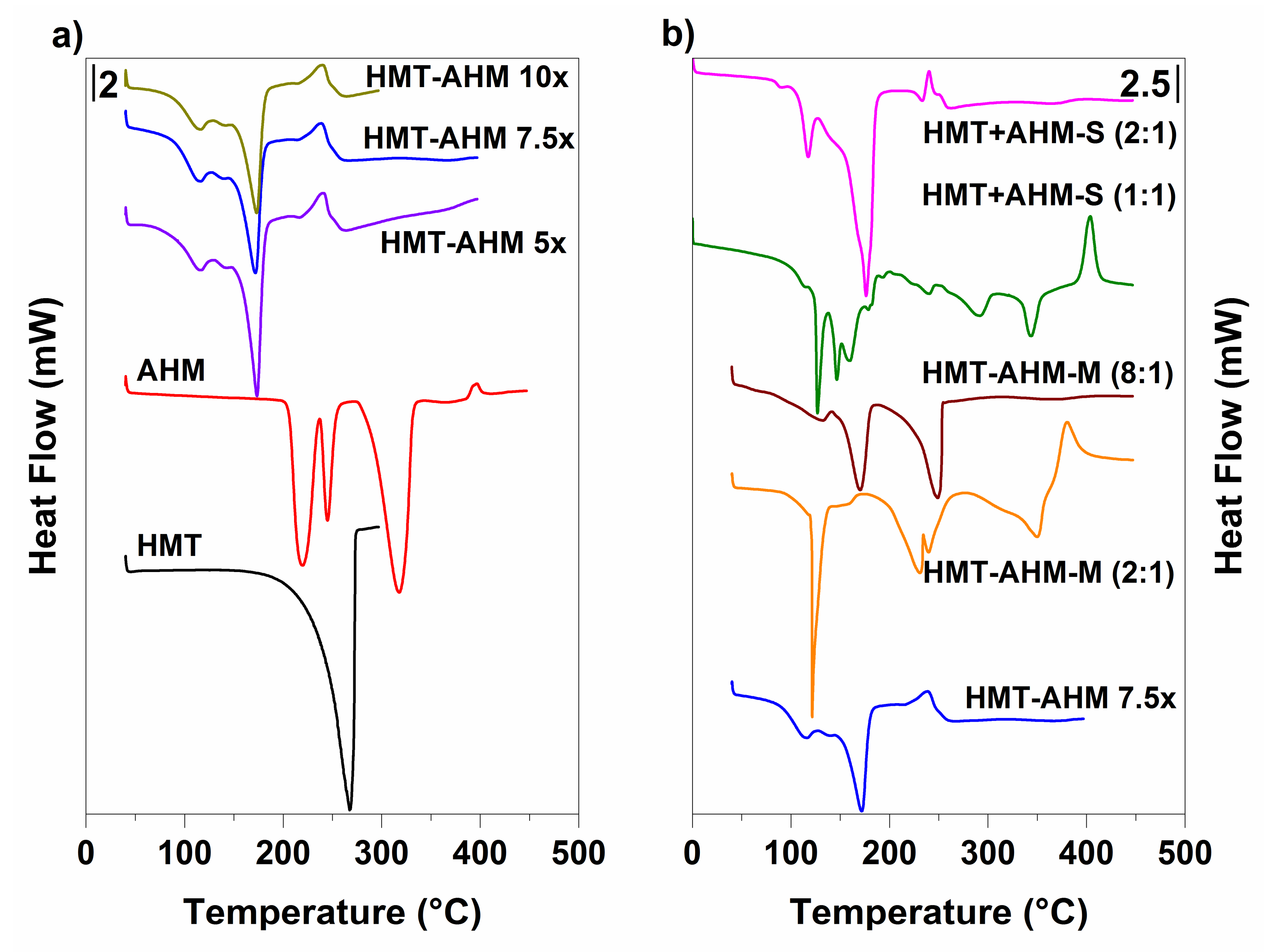
DSC results displayed in Figure 4 show that the HMT-AHM complexes prepared with different HMT excesses (HMT-AHM 5×, 7.5× and 10×), as in TGA, had identical profiles. In comparison with the samples HMT+AHM-M (2:1) and HMT+AHM-M (8:1), some differences to the HMT-AHM complex in the DSC signals were recorded.
HMT+AHM-M (2:1) had a sharp endothermic peak, which occurred in the temperature range of 110–130 °C, and the subsequent endothermic peaks at 250–350 °C correspond to AHM. The change in the molar ratio of HMT:AHM in HMT+AHM-M (8:1) sample also changed the DSC curve. Only two distinct peaks were observable on the record: the first endothermic peak at 170.51 °C corresponded to AHM decomposition and the second one at 248.73 °C to HMT sublimation.
According to the DSC records, the complexes obtained by crystallization of the HMT and AHM ammonia solutions differed among themselves and also in comparison with the HMT-AHM complex prepared by the Afanasiev method. Both HMT+AHM-S (1:1) and HMT+AHM-S (2:1), as well as HMT+AHM-M (2:1) complexes, were characterized by the endothermic peak around 120 °C, which was probably related to the sudden formation of another type of a complex. Despite the fact that the HMT-AHM complex had the same peak, but not quite at intensely, we can conclude that the complex is very similar, but not exactly identical to HMT+AHM-S (2:1). This difference also affected the final structure of molybdenum nitrides and carbides.
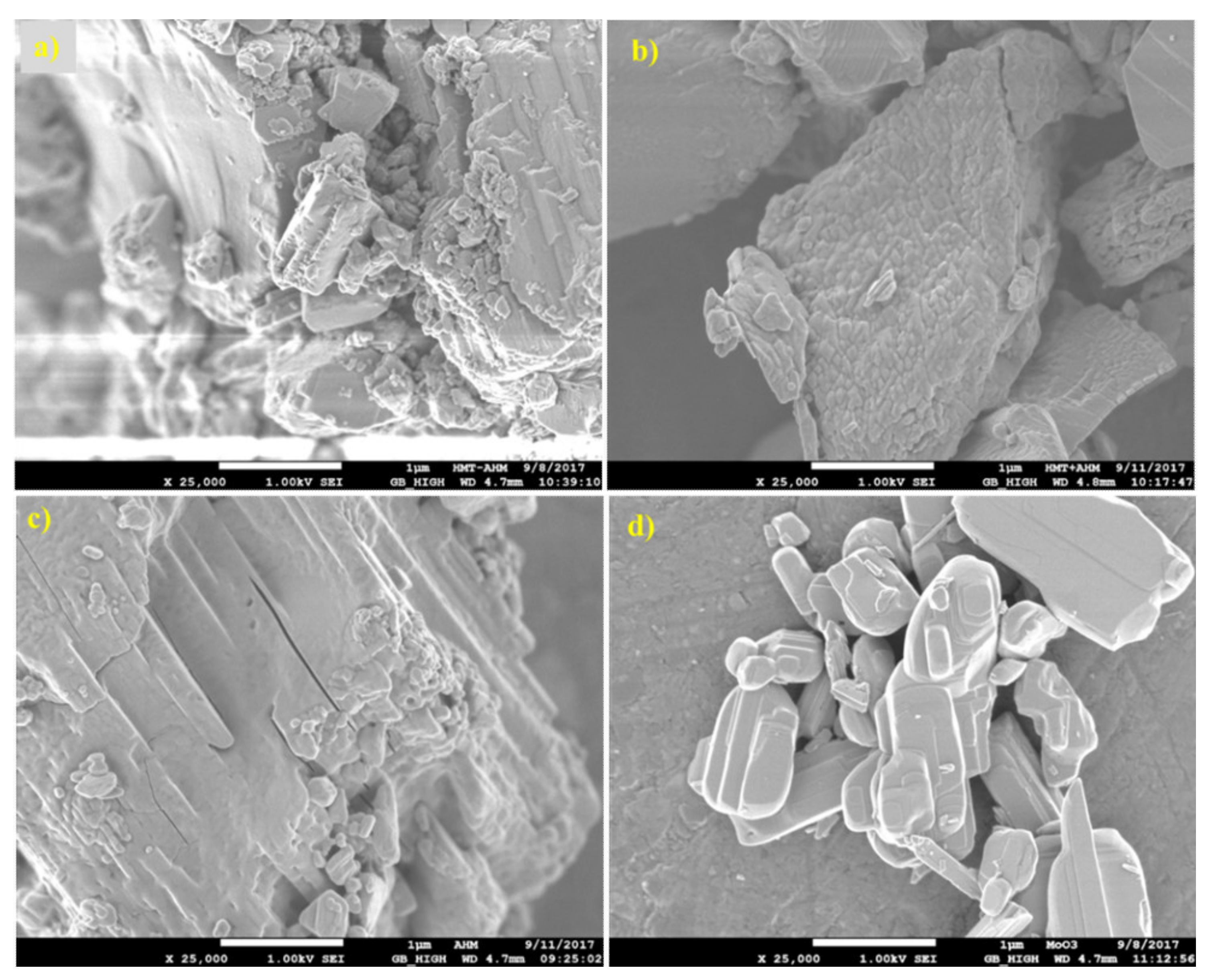
SEM results (Figure 5) show that the surface morphology of the HMT+AHM-S (2:1) sample was more crystallized than the HMT-AHM complex. The MoO3 sample has small molybdite crystals produced by thermal decomposition of AHM.
3.2. Non-Supported MoCx
Non-supported (bulk) molybdenum carbides were synthesised using 20 vol% CH4 in H2 with a flowrate of 75 cm3/min. All the prepared samples showed a high carbon content (Table 1), indicating their complete conversion to carbides. Only the sample where the AHM precursor was used and the reaction temperature was 600 °C contained much less carbon. This was confirmed by X-ray diffraction, where the majority phase was monoclinic MoO2 and at the same time a minor orthorhombic modification of α-Mo2C occurred. The fractions of the carbide phases and their crystallite sizes are shown in Table 1. As seen from the diffraction patterns of the samples synthesised from the AHM and HMT-AHM precursors at different temperatures (Figure 6), both of them provided a mixture of α- and β-Mo2C in the ratio of about 2:1 at 700 °C and only α-Mo2C at 800 °C. There was no complete conversion to any carbide phase at low temperatures for AHM (Figure 6a), while HMT-AHM (Figure 6b) gave hexagonal β-Mo2C already at 600 °C. Other precursors provided a pure α-Mo2C phase only at 700 °C (Figure 7).
The prepared carbides showed a relatively wide range of specific surface area values (Table 1). The samples synthesized from HMT+AHM-S (2:1) had an area two times higher than when HMT-AHM was used. The specific surface areas of the other samples were very small or even equal to zero, though they all contained the carbide phase.
The crystallites sizes (Table 1) were relatively equal. These values were mostly in the range from 14.3 to 21.3 nm for the α-Mo2C phase. The exception was AHM-800, the crystallite size of wich was 40.2 nm. The size of the β-Mo2C crystalline phase was possible to determine only for the sample HMT-AHM-600, where this phase appears separately. The size of β-Mo2C crystallites in this sample was 4.9 nm. In the case of AHM-700 and HMT-AHM-700, crystallite sizes could not be measured due to the overlap of corresponding diffraction lines. The crystallites sizes were calculated from the reflection of 39.5° 2 theta for α-Mo2C and 37.1° 2 theta for β-Mo2C.
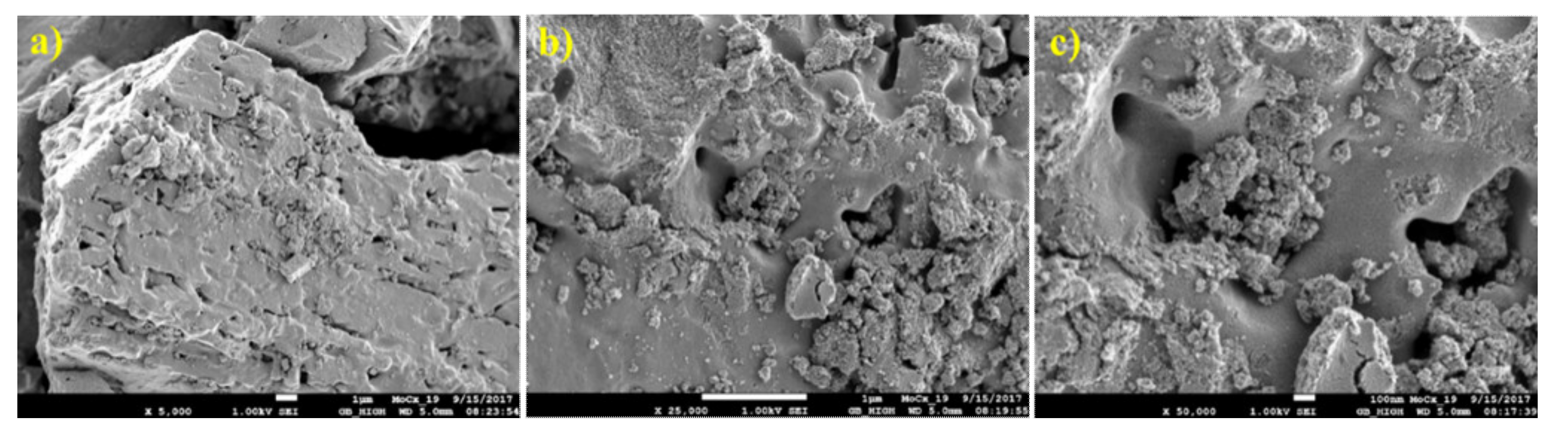
The structure of the prepared non-supported molybdenum carbides was analysed using scanning electron and optical microscopes. The samples synthesised from the HMT-AHM and HMT+AHM-S (2:1) complexes showed a well-crystallized structure, while the microcrystalline structure was peculiar to the samples obtained from AHM (Figure 8). Evaluation of the structure using SEM revealed a distinctive spongy (foam) structure of the prepared samples (Figure 9).
3.3. Non-Supported MoNx
All the non-supported (bulk) molybdenum nitrides were synthesised using the same conditions as for carbides. A mixture of 20 vol% H2 in N2 was used as a working gas. The specific surface area of the prepared materials and the nitrogen content were very dependent on the content and type of the nitride phase (Table 2). The maximum was 29 m2/g for the sample prepared from HMT+AHM-M (8:1), followed by HMT-AHM-700. Nitrogen content (Table 2) clearly showed that the nitride phase was produced only under certain conditions, while carbides were formed in the case of each precursor and temperature. A distinctive feature in nitride samples was the presence of carbon, indicating the presence of the carbide phase. The highest carbon and nitrogen were typical for the samples produced from HMT-AHM (700, 800 °C) and HMT+AHM-S (2:1) precursors. The presence of carbon can be explained by the incomplete decomposition of HMT, which was present in the structure of the used precursor complex. The minor phase was confirmed as orthorhombic carbide phase α-Mo2C, based on the XRD data.
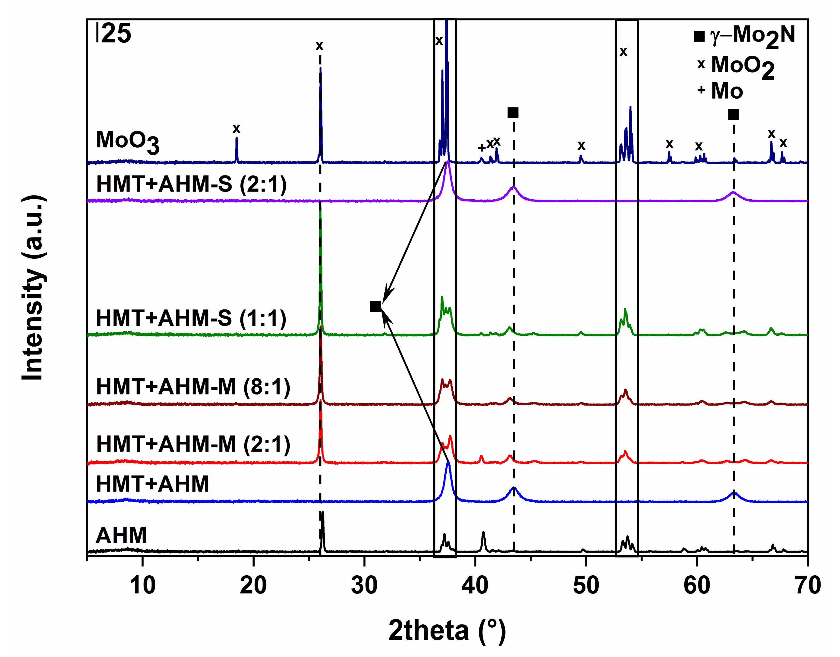
The use of the AHM precursor (Figure 10a) did not lead to the formation of molybdenum nitride; only traces of tetragonal β-Mo2N modification, the cubic phase of metallic molybdenum, and monoclinic MoO2 started to occur at 700 °C. Higher temperatures resulted in metal molybdenum and MoO2. Nitridation of HMT-AHM (Figure 10b) gave a cubic modification of γ-Mo2N accompanied by a small α-Mo2C fraction at 700 °C. Formation of β-Mo2N was observed at 800 °C and only metallic molybdenum was formed at 900 °C. The sample prepared from the HMT+AHM-S (2:1) precursor at 700 °C was cubic Mo3N2 with a small amount of α-Mo2C. The other precursors examined by XRD (Figure 11) produced a mixture of β-Mo2N with MoO2, in the case of the precursor HMT+AHM-S (1:1) (the mixture with a small proportion of metal molybdenum). An exception was for the previously mentioned HMT+AHM-S (2:1), where cubic Mo3N2 was formed with a small proportion of α-Mo2C. The MoO3 precursor was only partially reduced to MoO2 and produced a very small proportion of metallic molybdenum.
The crystallite sizes of the nitride phases are shown in Table 2. The biggest crystallite size was related to the β-Mo2N phase and determined at 37.4° 2 theta. The value was in two ranges of about 18 and 27 nm. Crystallite sizes of other presented phases γ-Mo2N (13.8 nm) and β-Mo2N (11.7 nm) were calculated at 37.5° and 37.7° 2 theta, respectively.
Optical and electron micrographs did not show any noticeable difference between molybdenum carbide and nitride samples (Figure 12 and Figure 13). Nitridation of HMT-AHM and HMT+AHM-S (2:1) precursor complexes also resulted in a very crystalline product, while HMT+AHM-M produced a microcrystalline product (Figure 12). The sponge structure was also typical for these materials (Figure 13), but was more distinct and produced labyrinths in comparison to carbides, where relatively small isolated circular pores were observed. When the HMT+AHM-S (1:1) precursor was used, a mixture of two different phases was observed (Figure 14a). A crystalline phase was composed of tugarinovite (MoO2) and sponge phases consisted of β-Mo2N phases. The same crystalline phase was observed when using the MoO3 precursor (Figure 14b).
The obtained data show that the investigated precursors had a high influence on the physico-chemical properties of the prepared materials. It was found that the carbide phase was easier to obtain than the pure nitride phase, which was observed only when using the HMT-AHM precursor at 800 °C, while the carbide phase was present at a temperature above 600 °C for all used precursors except AHM, giving mainly MoO2. The summarized scheme of the carburization/nitridation process of HMT-AHM is presented on Figure 15.
Another fact, confirming that the carbides were produced more easily (compare to nitrides), was evidenced by the presence of α-Mo2C formed from HMT-AHM and HMT+AHM-S (2:1) at 700 °C as a concomitant phase. Basing on these results, we can conclude that HMT-AHM and HMT+AHM-S (2:1) were the most effective precursors of molybdenum carbides and nitrides synthesis. Even though they were very similar, they were not identical materials.
3.4. Supported Samples
Basing on the synthesis of the non-supported molybdenum carbides and nitrides, the HMT-AHM precursor was chosen to prepare supported samples. HMT+AHM-S (2:1) on Al2O3# was used for the comparative study. The preparation temperature was 700 °C as a compromise between the formation of the desired phase and the avoidance of structural changes in the supports. The samples exhibited high molybdenum contents ranging from 22.1 to 38.4 wt% (Table 3). As a consequence, the high content of the carbide (MoCx) or nitride (MoNx) phases decreased the initial specific surface area of the SBA-15 and BEA supports.
When using the AZF support, the main purpose was to achieve a higher possible molybdenum loading to get a composite material with large cavities (up to tens of micrometres) filled with molybdenum carbide or nitride crystal particles. This was reasoned by the fact that the larger particles of carbide and nitride phases have better stability during the reactions and increased resistance to complete oxidation to crystalline metal oxides [49,50]. These materials were characterized by having the lowest specific surface area (16–28 m2/g), determined mainly by the surface of the bulk nitride or carbide phases located in macroporous cavities of the AZF support. The significant decrease of the area from the original was due to clogging micropores, as is the case of the BEA samples. However, there was no noticeable difference in comparing nitride and carbide samples in SBET reduction. Both groups showed very similar surface area values without any prevalence in blocking pores (Table 3).
The carbides except supported on TiO2 (0.16% of N) contained no nitrogen, or below the detection limit of the device. The carbon content varied between 0.49 and 2.57% for all samples. A small amount of carbon (0.08–0.45%) was inherent for each nitride sample and nitrogen was in similar values (0.21–2.38%) as carbon in carbides (Table 3). The low nitrogen and carbon contents could be caused by low amounts of impregnating complexes on ZrO2 and TiO2, which in turn was due to their low pore volumes.
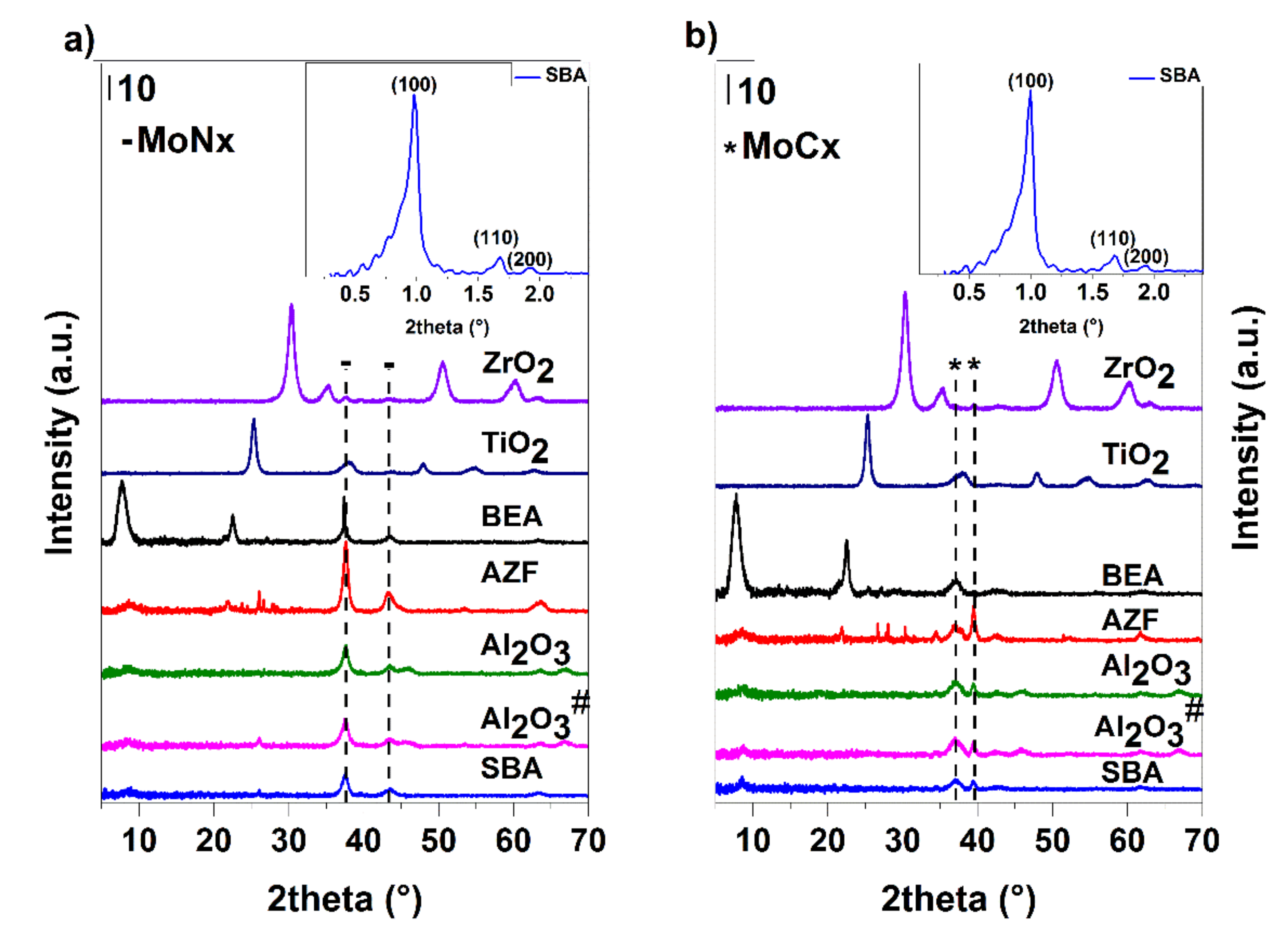
XRD results (Figure 16) showed that when Al2O3 was used as the support, well-dispersed carbides and nitrides phases were formed. In carbides samples, apart from α-Mo2C and Al2O3, the main phase was detected as amorphous. The nitrides, besides the main amorphous phase, also contained β-Mo2N accompanied by cubic Mo3N2 and Al2O3. In addition, the formation of a certain proportion of a cubic AlN phase cannot be excluded. The phase composition of MoCx on Al2O3# and Al2O3 was identical, but in the case of MoNx, the samples differed by predominant monoclinic MoO2 on Al2O3#. The synthesis of Al2O3# supported materials is more often used than the method with precursor complexes due to its simplicity [51,52,53]. However, in the case of nitrides, there was no complete conversion to the desired phase in these conditions. TiO2, in the case of carbide preparation, comprised the crystalline phase of anatase accompanied by the well-dispersed carbide phase containing α-Mo2C and β-Mo2C in the ratio of 40:60. The possible formation of a small fraction of the cubic delta phase cannot be excluded. The nitride pathway led the β-Mo2N phase accompanied by cubic Mo3N2. The dominant crystalline phase was anatase. A shift of the peak at about 38° 2 theta to the right can be explained as a partial overlapping of the carbide/nitride peak with the anatase phase of the support. A similar composition of the active phases was observed on ZrO2, which due to the small pore volume, contained only about half of the amount of molybdenum against the TiO2 support. The proportion of the carbide phases was identical, whereas, for nitrides, it was not possible to exclude the presence of the gamma phase. At the carbide pathway, the SBA-15 mesoporous silica provided a mixture of α-Mo2C and β-Mo2C at a ratio of about 40:60; in the case of the nitride pathway, there was a cubic Mo3N4 and a part of the monoclinic MoO2. The diffractogram, when measuring low angles, shows that the mesoporous structure was preserved (Figure 16). The obtained diffractograms also show the presence of reflections characteristic of microporous zeolite Beta and well-dispersed β-Mo2C and cubic Mo3N2 of carbide and nitride samples, respectively. Diffractograms of the samples prepared on AZF support show the presence of the zeolite phase (clinoptilolite) and crystalline α-Mo2C and β-Mo2C (approximately 60:40) and β-Mo2N, respectively. The influence of the support acidity on the formation of carbide or nitride phases was not clear. On the more acidic supports, in the case of carbides, a mixture of α- and β- phases was produced, while in the mixed nitride phase, the crystalline cubic phase of Mo3N2 was observed.
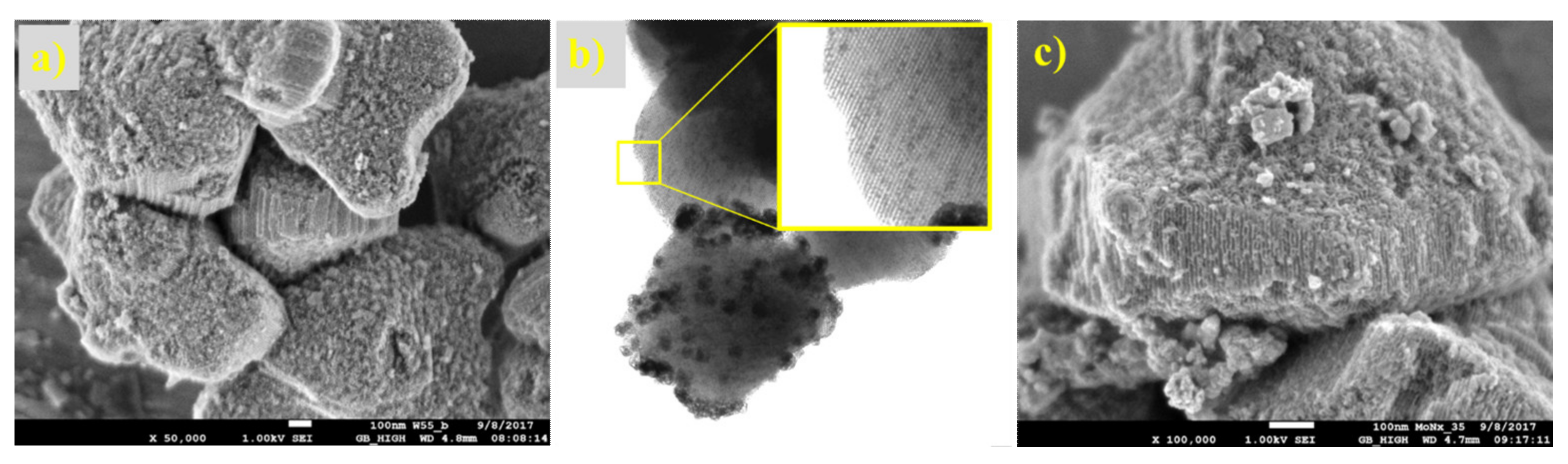
The microphotographs from the optical and electron microscope (Figure 17 and Figure 18) show the structure of the prepared supported samples. The composite samples on AZF had macroporous cavities filled with crystalline carbides (Figure 17). The porous structure did not change, even after heat treatment at 700 °C. On the detailed SEM image, a sponge-like structure with a large number of small pores is clearly visible. The samples prepared on the SBA-15 support are shown in Figure 18. A regular structure of the mesoporous silica SBA-15 was not disordered during the preparation of the carbides or nitrides, even at 700 °C. Its surface was formed by nitride or carbide crystals, probably shaped by precursor leakage from the cylindrical pores during heat treatment. The TEM image of carbided SBA-15 (Figure 18b) clearly shows in detail the basic mesoporous structure of SBA-15 that contained the MoCx nanocrystals inside the cylindrical pores and outside on the catalyst surface. Moreover, the dramatic decrease in the surface area of SBA-15 was confirmed by TEM, as the blockage caused by the formation of crystals inside the long cylindrical mesoporous structure of the support (Figure 18b).
The non-supported nitride sample was applied by Murzin’s group in the direct hydrodeoxygenation of algal lipids extracted from Chlorella alga, and found to be a perspective catalyst [54]. Other samples have been tested in different hydrotreatment reactions under batch and flow conditions conducted at UniCRE. Further evaluation of the results are under the publishing process.
According to the literature [22,35,36,44,45,55,56,57,58,59,60,61,62,63,64,65,66,67,68,69], the main precursor for the synthesis of supported molybdenum catalysts with the nitride or carbide active phases is considered to be AHM (MoO3), and less often the mixture of HMT with AHM, while the preparation of supported catalysts by the impregnation of the HMT-AHM complex is not practically used. AHM impregnated supports are initially calcined in the air to form MoO3 on the surface of the support. The most commonly used one is Al2O3 followed by SiO2/SBA-15. In the case of Mo2C containing catalysts, carbon (activated carbon, carbon black, nanotubes, etc.) is preferably used, which contributes to the formation of the carbide phase on the support surface.
4. Conclusions
This study set out the possibility of molybdenum carbide and nitride synthesis using various precursors and reaction conditions. Based on the analysis of the studied supported and bulk materials, the most suitable preparation conditions to obtain the desired phases were considered. The ability to prepare carbide and nitride phases was demonstrated on the commonly used supports Al2O3, TiO2, ZrO2, SBA-15, and zeolite Beta, and also on the less common AZF support. It was investigated that the synthesis of target molybdenum nitrides strongly depends on the structure of the precursor and temperature conditions, while the synthesis of carbide samples always led to the target phase composition. Unlike the carbide samples, where the α-Mo2C phase was predominant during nitridation, the mixture of β-Mo2N and MoO2 with a small amount of metal molybdenum was generally formed. However, using the precursor complex obtained from the mixture of hexamethylenetetramine with ammonium heptamolybdate (HMT-AHM), the pure phase of molybdenum nitride was achieved at 800 °C. At 700 °C, γ-Mo2N with a small amount of α-Mo2C was formed from the same precursor. A similar situation occurred when using the precursor synthesized by evaporation of the ammonia solution of HMT with AHM at a molar ratio of 2:1, where the resulting cubic Mo3N2 phase was also accompanied by a small amount of α-Mo2C at 700 °C. Supported samples, even at the high molybdenum content, had the high dispersion of the phases. All carbide samples were composed of α- and β-Mo2C mixtures. Nitrides supported on Al2O3 consisted of β-Mo2N, and on TiO2 and ZrO2 consisted of β- and γ- Mo2N mixtures, SBA-15, and BEA, despite the β- and γ-phases also containing Mo3N2 and Mo3N4. The composite samples prepared on the foamed AZF support included cavities filled with crystalline α- and β-Mo2C in the case of carbides and the β-Mo2N crystalline phase for nitrides.
Author Contributions
Conceptualization, design of the experiments, analysis of the data, writing—original draft preparation, Z.T.; synthesis, L.S.; analytical measuring, R.V. and L.P.; supervision, writing—review and editing, U.A.
Funding
The publication is a result of the project Development of the UniCRE Centre (LO1606), which has been financially supported by the Ministry of Education, Youth, and Sports of the Czech Republic (MEYS) under the National Sustainability Program I. The result was achieved using the infrastructure of the project Efficient Use of Energy Resources Using Catalytic Processes (LM2015039), which has been financially supported by MEYS within the targeted support of large infrastructures.
Acknowledgments
Special thanks to the University of Pardubice (Czech Republic) for SEM images processing, to the Åbo Akademi Process Chemistry Centre (Finland), and Markus Peurla (University of Turku, Finland) for the TEM analysis.
Conflicts of Interest
The authors declare no conflict of interest.
References
- Calaisa, J.L. Band structure of transition metal compounds. Adv. Phys. 1977, 26, 847–885. [Google Scholar] [CrossRef]
- Wu, M.; Lin, X.; Hagfeldt, A.; Ma, T. Low-cost molybdenum carbide and tungsten carbide counter electrodes for dye-sensitized solar cells. Angew. Chem. Int. Ed. 2011, 50, 3520–3524. [Google Scholar] [CrossRef]
- Oyama, S.T. Preparation and catalytic properties of transition metal carbides and nitrides. Catal. Today 1992, 15, 179–200. [Google Scholar] [CrossRef]
- Furimsky, E. Metal carbides and nitrides as potential catalysts for hydroprocessing. Appl. Catal. A Gen. 2003, 240, 1–28. [Google Scholar] [CrossRef]
- Abe, H.; Cheung, T. Keung; Bell, A.T. The activity of transition metal nitrides for hydrotreating quinoline and thiophene. Catal. Lett. 1993, 21, 11–18. [Google Scholar] [CrossRef]
- Zhao, Y.; Kamiya, K.; Hashimoto, K.; Nakanishi, S. In situ CO2-emission assisted synthesis of molybdenum carbonitride nanomaterial as hydrogen evolution electrocatalyst. J. Am. Chem. Soc. 2015, 137, 110–113. [Google Scholar] [CrossRef] [PubMed]
- Neylon, M.K.; Choi, S.; Kwon, H.; Curry, K.E.; Thompson, L.T. Catalytic properties of early transition metal nitrides and carbides: N-butane Hydrogenolysis, dehydrogenation and isomerization. Appl. Catal. A Gen. 1999, 183, 253–263. [Google Scholar] [CrossRef]
- Al Shalwi, M. The Preparation of Molybdenum Carbonitrides by Single Source Routes and a Study of Their Lattice. Master’s Thesis, University of Glasgow, Glasgow, UK, May 2012. [Google Scholar]
- Oyama, S.T. Introduction to the chemistry of transition metal carbides and nitrides. In The Chemistry of Transition Metal Carbides and Nitrides; Springer: Berlin, Germany, 1996; pp. 1–27. [Google Scholar]
- Nakajima, T. Chemical vapor deposition of tungsten carbide, molybdenum carbide nitride, and molybdenum nitride films. J. Electrochem. Soc. 1997, 144, 2096. [Google Scholar] [CrossRef]
- Hyeon, T.; Fang, M.; Suslick, K.S. Nanostructured molybdenum carbide: Sonochemical synthesis and catalytic properties. J. Am. Chem. Soc. 1996, 118, 5492–5493. [Google Scholar] [CrossRef]
- Pang, M.; Li, C.; Ding, L.; Zhang, J.; Su, D.; Li, W.; Liang, C. Microwave-assisted preparation of Mo2C/CNTs nanocomposites as efficient electrocatalyst supports for oxygen reduction reaction. Ind. Eng. Chem. Res. 2010, 49, 4169–4174. [Google Scholar] [CrossRef]
- Bystrov, Y.A.; Vetrov, N.Z.; Lisenkov, A.A. Plasmachemical synthesis of carbide compounds in metal-containing plasma jet from vacuum arc discharge. Tech. Phys. Lett. 2008, 34, 734–736. [Google Scholar] [CrossRef]
- Merzhanov, A.G.; Borovinskaya, I.P. Self-propagated high-temperature synthesis of refractory inorganic compounds. Doklady Akademii Nauk SSSR 1972, 204, 366–369. [Google Scholar]
- Guil-López, R.; Nieto, E.; Botas, J.A.; Fierro, J.L.G. On the genesis of molybdenum carbide phases during reduction-carburization reactions. J. Solid State Chem. 2012, 190, 285–295. [Google Scholar] [CrossRef]
- Schaidle, J.A.; Schweitzer, N.M.; Ajenifujah, O.T.; Thompson, L.T. On the preparation of molybdenum carbide-supported metal catalysts. J. Catal. 2012, 289, 210–217. [Google Scholar] [CrossRef]
- Chai, S.H.; Schwartz, V.; Howe, J.Y.; Wang, X.; Kidder, M.; Overbury, S.H.; Dai, S.; Jiang, D.E. Graphitic mesoporous carbon-supported molybdenum carbides for catalytic hydrogenation of carbon monoxide to mixed alcohols. Microporous Mesoporous Mater. 2013, 170, 141–149. [Google Scholar] [CrossRef]
- Tang, C.; Sun, A.; Xu, Y.; Wu, Z.; Wang, D. High specific surface area Mo2C nanoparticles as an efficient electrocatalyst for hydrogen evolution. J. Power Sources 2015, 296, 18–22. [Google Scholar] [CrossRef]
- Vitale, G.; Guzmán, H.; Frauwallner, M.L.; Scott, C.E.; Pereira-Almao, P. Synthesis of nanocrystalline molybdenum carbide materials and their characterization. Catal. Today 2015, 250, 123–133. [Google Scholar] [CrossRef]
- Preiss, H.; Meyer, B.; Olschewski, C. Preparation of molybdenum and tungsten carbides from solution derived precursors. J. Mater. Sci. 1998, 33, 713–722. [Google Scholar] [CrossRef]
- Patel, M.; Subrahmanyam, J. Synthesis of nanocrystalline molybdenum carbide (Mo2C) by solution route. Mater. Res. Bull. 2008, 43, 2036–2041. [Google Scholar] [CrossRef]
- Baklanova, O.N.; Vasilevich, A.V.; Lavrenov, A.V.; Drozdov, V.A.; Muromtsev, I.V.; Arbuzov, A.B.; Trenikhin, V.; Sigaeva, S.S.; Temerev, V.L.; Gorbunova, O.V.; et al. Molybdenum carbide synthesized by mechanical activation an inert medium. J. Alloys Compd. 2017, 698, 1018–1027. [Google Scholar] [CrossRef]
- Torabi, O.; Golabgir, M.H.; Tajizadegan, H.; Torabi, H. A study on mechanochemical behavior of MoO3-Mg-C to synthesize molybdenum carbide. Int. J. Refract. Met. Hard Mater. 2014, 47, 18–24. [Google Scholar] [CrossRef]
- Saghafi, M.; Ataie, A.; Heshmati-Manesh, S. Effects of mechanical activation of MoO3/C powder mixture in the processing of nano-crystalline molybdenum. Int. J. Refract. Met. Hard Mater. 2011, 29, 419–423. [Google Scholar] [CrossRef]
- Khabbaz, S.; Honarbakhsh-Raouf, A.; Ataie, A.; Saghafi, M. Effect of processing parameters on the mechanochemical synthesis of nanocrystalline molybdenum carbide. Int. J. Refract. Met. Hard Mater. 2013, 41, 402–407. [Google Scholar] [CrossRef]
- Choi, J.-G.; Brenner, J.R.; Colling, C.W.; Demczyk, B.G.; Dunning, J.L.; Thompson, L.T. Synthesis and characterization of molybdenum nitride hydrodenitrogenation catalysts. Catal. Today 1992, 15, 201–222. [Google Scholar] [CrossRef]
- Wolden, C.A.; Pickerell, A.; Gawai, T.; Parks, S.; Hensley, J.; Way, J.D. Synthesis of β-Mo2C thin films. ACS Appl. Mater. Interfaces 2011, 3, 517–521. [Google Scholar] [CrossRef] [PubMed]
- Wang, T.; Liu, X.; Wang, S.; Huo, C.; Li, Y.W.; Wang, J.; Jiao, H. Stability of β-Mo2C facets from Ab initio atomistic thermodynamics. J. Phys. Chem. C 2011, 115, 22360–22368. [Google Scholar] [CrossRef]
- Wang, T.; Wang, S.; Li, Y.W.; Wang, J.; Jiao, H. Adsorption equilibria of CO coverage on β-Mo2C surfaces. J. Phys. Chem. C 2012, 116, 6340–6348. [Google Scholar] [CrossRef]
- Zhu, Q.; Chen, Q.; Yang, X.; Ke, D. A new method for the synthesis of molybdenum carbide. Mater. Lett. 2007, 61, 5173–5174. [Google Scholar] [CrossRef]
- Vitale, G.; Frauwallner, M.L.; Hernandez, E.; Scott, C.E.; Pereira-Almao, P. Low temperature synthesis of cubic molybdenum carbide catalysts via pressure induced crystallographic orientation of MoO3 precursor. Appl. Catal. A Gen. 2011, 400, 221–229. [Google Scholar] [CrossRef]
- Xiao, T.C.; York, A.P.E.; Williams, V.C.; Al-Megren, H.; Hanif, A.; Zhou, X.Y.; Green, M.L.H. Preparation of molybdenum carbides using butane and their catalytic performance. Chem. Mater. 2000, 12, 3896–3905. [Google Scholar] [CrossRef]
- Bouchy, C.; Derouane-Abd Hamid, S.B.; Derouane, E.G. A new route to the metastable FCC molybdenum carbide α-MoC. Chem. Commun. 2000, 125–126. [Google Scholar] [CrossRef]
- Bouchy, C.; Schmidt, I.; Anderson, J.; Jacobsen, C.J.; Derouane, E.; Derouane-Abd Hamid, S. Metastable fcc α-MoC1−x supported on HZSM5: Preparation and catalytic performance for the non-oxidative conversion of methane to aromatic compounds. J. Mol. Catal. A Chem. 2000, 163, 283–296. [Google Scholar] [CrossRef]
- Miyao, T.; Shishikura, I.; Matsuoka, M.; Nagai, M.; Oyama, S.T. Preparation and characterization of alumina-supported molybdenum carbide. Appl. Catal. A Gen. 1997, 165, 419–428. [Google Scholar] [CrossRef]
- Koós, Á.; Solymosi, F. Production of CO-free H2 by formic acid decomposition over Mo2C/carbon catalysts. Catal. Lett. 2010, 138, 23–27. [Google Scholar] [CrossRef]
- Leclercq, L.; Provost, M.; Pastor, H.; Grimblot, J.; Hardy, A.M.; Gengembre, L.; Leclercq, G. Catalytic properties of transition metal carbides. I. Preparation and physical characterization of bulk mixed carbides of molybdenum and tungsten. J. Catal. 1989, 117, 371–383. [Google Scholar] [CrossRef]
- Ma, Y.; Guan, G.; Shi, C.; Zhu, A.; Hao, X.; Wang, Z.; Kusakabe, K.; Abudula, A. Low-temperature steam reforming of methanol to produce hydrogen over various metal-doped molybdenum carbide catalysts. Int. J. Hydrogen Energy 2014, 39, 258–266. [Google Scholar] [CrossRef] [Green Version]
- Bej, S.K.; Bennett, C.A.; Thompson, L.T. Acid and base characteristics of molybdenum carbide catalysts. Appl. Catal. A Gen. 2003, 250, 197–208. [Google Scholar] [CrossRef]
- Lee, W.S.; Wang, Z.; Wu, R.J.; Bhan, A. Selective vapor-phase hydrodeoxygenation of anisole to benzene on molybdenum carbide catalysts. J. Catal. 2014, 319, 44–53. [Google Scholar] [CrossRef]
- Lee, J.S.; Oyama, S.T.; Boudart, M. Molybdenum carbide catalysts. I. Synthesis of unsupported powders. J. Catal. 1987, 106, 125–133. [Google Scholar] [CrossRef]
- Roy, A.; Serov, A.; Artyushkova, K.; Brosha, E.L.; Atanassov, P.; Ward, T.L. Facile synthesis of high surface area molybdenum nitride and carbide. J. Solid State Chem. 2015, 228, 232–238. [Google Scholar] [CrossRef]
- Afanasiev, P. New single source route to the molybdenum nitride Mo2N. Inorg. Chem. 2002, 41, 5317–5319. [Google Scholar] [CrossRef] [PubMed]
- Wang, Z.-Q.; Zhang, Z.-B.; Zhang, M.-H. The efficient synthesis of a molybdenum carbide catalyst via H2-thermal treatment of a Mo(VI)-hexamethylenetetramine complex. Dalton Trans. 2011, 40, 1098–1104. [Google Scholar] [CrossRef] [PubMed]
- Wang, H.M.; Wang, X.H.; Zhang, M.H.; Du, X.Y.; Li, W.; Tao, K.Y. Synthesis of bulk and supported molybdenum carbide by a single-step thermal carburization method. Chem. Mater. 2007, 19, 1801–1807. [Google Scholar] [CrossRef]
- Huo, X.; Wang, Z.; Huang, J.; Zhang, R.; Fang, Y. Bulk Mo and Co-Mo carbides as catalysts for methanation. Catal. Commun. 2016, 79, 39–44. [Google Scholar] [CrossRef]
- Kovács, T.N.; Hunyadi, D.; de Lucena, A.L.A.; Szilágyi, I.M. Thermal decomposition of ammonium molybdates. J. Therm. Anal. Calorim. 2016, 124, 1013–1021. [Google Scholar] [CrossRef] [Green Version]
- Chouzier, S.; Czeri, T.; Roy-Auberger, M.; Pichon, C.; Geantet, C.; Vrinat, M.; Afanasiev, P. Decomposition of molybdatehexamethylenetetramine complex: One single source route for different catalytic materials. J. Solid State Chem. 2011, 184, 2668–2677. [Google Scholar] [CrossRef]
- Stellwagen, D.R.; Bitter, J.H. Structure–performance relations of molybdenum- and tungsten carbide catalysts for deoxygenation. Green Chem. 2015, 17, 582–593. [Google Scholar] [CrossRef]
- Alexander, A.-M.; Hargreaves, J.S.J. Alternative catalytic materials: Carbides, nitrides, phosphides and amorphous boron alloys. Chem. Soc. Rev. 2010, 39, 4388–4401. [Google Scholar] [CrossRef] [PubMed]
- Wang, H.M.; Du, X.Y.; Zhang, M.H.; Li, W.; Tao, K.Y. Synthesis of bulk and alumina-supported γ-Mo2N catalysts by a single-step complex decomposition method. Catal. Today 2008, 131, 156–161. [Google Scholar] [CrossRef]
- Wang, H.; Li, W.; Zhang, M. New approach to the synthesis of bulk and supported bimetallic molybdenum nitrides. Chem. Mater. 2005, 17, 3262–3267. [Google Scholar] [CrossRef]
- Wang, X.H.; Zhang, M.H.; Li, W.; Tao, K.Y. A simple synthesis route and characterisation of Co3Mo3C. Dalt. Trans. 2007, 5165–5170. [Google Scholar] [CrossRef] [PubMed]
- Nguyen, H.S.H.; Mäki-Arvela, P.; Akhmetzyanova, U.; Tišler, Z.; Hachemi, I.; Rudnäs, A.; Smeds, A.; Eränen, K.; Aho, A.; Kumar, N.; et al. Direct hydrodeoxygenation of algal lipids extracted from Chlorella alga. J. Chem. Technol. Biotechnol. 2017, 92, 741–748. [Google Scholar] [CrossRef]
- Yao, Z.W. Exploration on synthesis of activated carbon supported molybdenum carbide, nitride and phosphide via carbothermal reduction route. J. Alloys Compd. 2009, 475, L38–L41. [Google Scholar] [CrossRef]
- Pielaszek, J.; Mierzwa, B.; Medjahdi, G.; Marêché, J.F.; Puricelli, S.; Celzard, A.; Furdin, G. Molybdenum carbide catalyst formation from precursors deposited on active carbons: XRD studies. Appl. Catal. A Gen. 2005, 296, 232–237. [Google Scholar] [CrossRef]
- Wang, X.H.; Hao, H.L.; Zhang, M.H.; Li, W.; Tao, K.Y. Synthesis and characterization of molybdenum carbides using propane as carbon source. J. Solid State Chem. 2006, 179, 538–543. [Google Scholar] [CrossRef]
- Wu, Q.; Christensen, J.M.; Chiarello, G.L.; Duchstein, L.D.L.; Wagner, J.B.; Temel, B.; Grunwaldt, J.D.; Jensen, A.D. Supported molybdenum carbide for higher alcohol synthesis from syngas. Catal. Today 2013, 215, 162–168. [Google Scholar] [CrossRef] [Green Version]
- Darujati, A.R.S.; Thomson, W.J. Stability of supported and promoted-molybdenum carbide catalysts in dry-methane reforming. Appl. Catal. A Gen. 2005, 296, 139–147. [Google Scholar] [CrossRef]
- Du, X.; France, L.J.; Kuznetsov, V.L.; Xiao, T.; Edwards, P.P.; AlMegren, H.; Bagabas, A. Dry reforming of methane over ZrO2-supported Co–Mo carbide catalyst. Appl. Petrochem. Res. 2014, 4, 137–144. [Google Scholar] [CrossRef]
- Vo, D.V.N.; Adesina, A.A. Fischer-Tropsch synthesis over alumina-supported molybdenum carbide catalyst. Appl. Catal. A Gen. 2011, 399, 221–232. [Google Scholar] [CrossRef]
- McCrea, K.R.; Logan, J.W.; Tarbuck, T.L.; Heiser, J.L.; Bussell, M.E. thiophene hydrodesulfurization over alumina-supported molybdenum carbide and nitride catalysts: Effect of Mo loading and phase. J. Catal. 1997, 171, 255–267. [Google Scholar] [CrossRef]
- Boullosa-Eiras, S.; Lødeng, R.; Bergem, H.; Stöcker, M.; Hannevold, L.; Blekkan, E.A. Catalytic hydrodeoxygenation (HDO) of phenol over supported molybdenum carbide, nitride, phosphide and oxide catalysts. Catal. Today 2014, 223, 44–53. [Google Scholar] [CrossRef]
- Brungs, A.J.; York, A.P.E.; Claridge, J.B.; Márquez-Alvarez, C.; Green, M.L.H. Dry reforming of methane to synthesis gas over supported molybdenum carbide catalysts. Catal. Lett. 2000, 70, 117–122. [Google Scholar] [CrossRef]
- Nagai, M.; Miyao, T.; Tuboi, T. Hydrodesulfurization of dibenzothiophene on alumina-supported molybdenum nitride. Catal. Lett. 1993, 18, 9–14. [Google Scholar] [CrossRef]
- Colling, C.W.; Thompson, L.T. The structure and function of supported molybdenum nitride hydrodenitrogenation catalysts. J. Catal. 1994, 146, 193–203. [Google Scholar] [CrossRef]
- Zhong, H.; Zhang, H.; Liu, G.; Liang, Y.; Hu, J.; Yi, B. A novel non-noble electrocatalyst for PEM fuel cell based on molybdenum nitride. Electrochem. Commun. 2006, 8, 707–712. [Google Scholar] [CrossRef]
- Chen, X.; Zhang, T.; Xia, L.; Li, T.; Zheng, M.; Wu, Z.; Wang, X.; Wei, Z.; Xin, Q.; Li, C. Catalytic decomposition of hydrazine over supported molybdenum nitride catalysts in a monopropellant thruster. Catal. Lett. 2002, 79, 21–25. [Google Scholar] [CrossRef]
- Tyrone Ghampson, I.; Sepúlveda, C.; Garcia, R.; García Fierro, J.L.; Escalona, N.; Desisto, W.J. Comparison of alumina- and SBA-15-supported molybdenum nitride catalysts for hydrodeoxygenation of guaiacol. Appl. Catal. A Gen. 2012, 435–436, 51–60. [Google Scholar] [CrossRef]
Figure 1.
A scheme of the reactor for the preparation of nitrides and carbides, where 1 = gas flow rate controller, 2 = temperature controller, 3 = triple-zone electric oven, 4 = quartz cuvette with a sample.
Figure 1.
A scheme of the reactor for the preparation of nitrides and carbides, where 1 = gas flow rate controller, 2 = temperature controller, 3 = triple-zone electric oven, 4 = quartz cuvette with a sample.

Figure 2.
X-ray diffraction patterns of the synthesized precursors and the starting feedstock.

Figure 3.
Thermogravimetric analysis of the synthesised precursors (a) and the starting feedstock (b).
Figure 3.
Thermogravimetric analysis of the synthesised precursors (a) and the starting feedstock (b).

Figure 4.
Thermal behavior of the synthesised precursors (a) and the starting feedstock (b) provided by differential scanning calorimetry (DSC).
Figure 4.
Thermal behavior of the synthesised precursors (a) and the starting feedstock (b) provided by differential scanning calorimetry (DSC).

Figure 5.
Scanning electron microscopic (SEM) micrographs of the synthesised precursors (a) HMT-AHM 7.5× and (b) HMT-AHM-S (2:1), and the starting feedstock (c) AHM and (d) MoO3.
Figure 5.
Scanning electron microscopic (SEM) micrographs of the synthesised precursors (a) HMT-AHM 7.5× and (b) HMT-AHM-S (2:1), and the starting feedstock (c) AHM and (d) MoO3.

Figure 6.
X-ray diffraction patterns of the molybdenum carbides prepared from AHM (a) and HMT-AHM (b) at 600–800 °C.
Figure 6.
X-ray diffraction patterns of the molybdenum carbides prepared from AHM (a) and HMT-AHM (b) at 600–800 °C.

Figure 7.
X-ray diffraction patterns of the molybdenum carbides prepared from different precursors at 700 °C.
Figure 7.
X-ray diffraction patterns of the molybdenum carbides prepared from different precursors at 700 °C.

Figure 8.
Microscope images of molybdenum carbides at 25× magnification obtained from (a) HMT-AHM-700, (b) AHM-800, (c) HMT+AHM-S (2:1)-700.
Figure 8.
Microscope images of molybdenum carbides at 25× magnification obtained from (a) HMT-AHM-700, (b) AHM-800, (c) HMT+AHM-S (2:1)-700.

Figure 9.
SEM images of molybdenum carbides synthesised from HMT-AHM-600 at magnifications of (a) 5000×, (b) 25,000×, and (c) 100,000×.
Figure 9.
SEM images of molybdenum carbides synthesised from HMT-AHM-600 at magnifications of (a) 5000×, (b) 25,000×, and (c) 100,000×.

Figure 10.
X-ray diffraction patterns of the molybdenum nitrides prepared from AHM (a) and HMT-AHM (b) at 700–900 °C.
Figure 10.
X-ray diffraction patterns of the molybdenum nitrides prepared from AHM (a) and HMT-AHM (b) at 700–900 °C.

Figure 11.
X-ray diffraction patterns of the molybdenum nitrides prepared at 700 °C.

Figure 12.
Microphotographs of the samples at 25× magnification: (a) HMT-AHM-700, (b) HMT+AHM-M (8:1), and (c) HMT+AHM-S (2:1).
Figure 12.
Microphotographs of the samples at 25× magnification: (a) HMT-AHM-700, (b) HMT+AHM-M (8:1), and (c) HMT+AHM-S (2:1).

Figure 13.
SEM images of HMT-AHM-700 in different magnifications: (a) 5000×, (b) 25,000×, and (c) 100,000×.
Figure 13.
SEM images of HMT-AHM-700 in different magnifications: (a) 5000×, (b) 25,000×, and (c) 100,000×.

Figure 14.
SEM images of (a) HMT+AHM-S (1:1) and (b) MoO3 prepared at 700 °C (magnifications of 25,000× and 100,000×).
Figure 14.
SEM images of (a) HMT+AHM-S (1:1) and (b) MoO3 prepared at 700 °C (magnifications of 25,000× and 100,000×).

Figure 15.
A general scheme of the carburization/nitridation process of HMT-AHM.

Figure 16.
X-ray diffraction patterns of the supported catalysts prepared by different pathways: nitrides (a) and carbides (b).
Figure 16.
X-ray diffraction patterns of the supported catalysts prepared by different pathways: nitrides (a) and carbides (b).

Figure 17.
Microphotographs of the samples at 6.3× magnification for (a) foamed AZF support, (b) carbided AZF composite, and (c) detailed structure of the carbide layer made by SEM (5000× and 100,000×).
Figure 17.
Microphotographs of the samples at 6.3× magnification for (a) foamed AZF support, (b) carbided AZF composite, and (c) detailed structure of the carbide layer made by SEM (5000× and 100,000×).

Figure 18.
Microphotographs of the samples supported on SBA-15 for (a) SEM of the carbide sample (50,000×), (b) TEM of the carbide sample, and (c) SEM of the nitride sample (100,000×)
Figure 18.
Microphotographs of the samples supported on SBA-15 for (a) SEM of the carbide sample (50,000×), (b) TEM of the carbide sample, and (c) SEM of the nitride sample (100,000×)


Table 1.
Physicochemical properties of the prepared molybdenum carbides.
| Sample | SBET (m2/g) | Elemental Analysis (wt%) | Content of Crystalline Phase (%)/Crystallite Size D (nm) | |||
|---|---|---|---|---|---|---|
| C | N | β-Mo2C | α-Mo2C | MoO2 | ||
| AHM-600 | 3.9 | 1.64 | <0.05 | - | 12/18.2 | 88/- |
| AHM-700 | 7.4 | 5.41 | <0.05 | 34/- | 66/14.3 | - |
| AHM-800 | 5.3 | 6.32 | <0.05 | - | 100/40.2 | - |
| HMT-AHM-600 * | 19.4 | 5.49 | <0.05 | 100/4.9 | - | - |
| HMT-AHM-700 * | 25.3 | 6.52 | <0.05 | 32/- | 68/14.6 | - |
| HMT-AHM-800 * | 14.1 | 8.34 | <0.05 | - | 100/21.3 | - |
| HMT+AHM-S (1:1) ** | 16.2 | 4.96 | <0.05 | - | 100/18.4 | - |
| HMT+AHM-S (2:1) ** | 51.8 | 4.43 | <0.05 | - | 100/15.1 | - |
| HMT+AHM-M (2:1) ** | 8.7 | 5.66 | <0.05 | - | 100/21.3 | - |
| HMT+AHM-M (8:1) ** | 18.3 | 6.27 | <0.05 | - | 100/19.8 | - |
| MoO3 ** | 0.0 | 5.81 | <0.05 | - | 100/18.5 | - |
* HMT-AHM 7.5× precursor, ** preparation at 700 °C.
Table 2.
Physicochemical properties of the prepared molybdenum nitrides.
| Sample | SBET (m2/g) | Elemental Analysis (wt%) | Content of Crystalline Phase (%)/Crystallite Size D (nm) | |||||
|---|---|---|---|---|---|---|---|---|
| C | N | β-Mo2N | γ-Mo2N | Mo3N2 | Mo | MoO2 | ||
| AHM-700 | 0.0 | <0.05 | 0.37 | 19/27.4 | - | - | 36/- | 45/- |
| AHM-800 | 0.0 | 0.05 | <0.05 | - | - | - | 57/- | 43/- |
| AHM-900 | 0.1 | <0.05 | <0.05 | - | - | - | 69/- | 31/- |
| HMT-AHM-700 * | 25.0 | 0.45 | 5.68 | - | 100/13.8 | - | - | - |
| HMT-AHM-800 * | 11.5 | <0.05 | 5.96 | 100/26.0 | - | - | - | - |
| HMT-AHM-900 * | 0.0 | <0.05 | <0.05 | - | - | - | 100/- | - |
| HMT+AHM-S (1:1) ** | 16.2 | 0.15 | 2.44 | 14/18.3 | - | - | - | 86/- |
| HMT+AHM-S (2:1) ** | 13.2 | 0.54 | 5.95 | - | - | 100/11.7 | - | - |
| HMT+AHM-M (2:1) ** | 12.2 | 0.15 | 2.32 | 78/17.6 | - | - | 1/- | 21/- |
| HMT+AHM-M (8:1) ** | 29.0 | 0.09 | 0.97 | 76/17.5 | - | - | - | 24/- |
| MoO3 ** | 0.3 | <0.05 | <0.05 | - | - | - | 2/- | 98/- |
* HMT-AHM 7.5× precursor, ** preparation at 700 °C.
Table 3.
Chemical composition and specific surface areas of the supported samples.
| Support | Initial SBET (m2/g) | Supported Nitrides | Supported Carbides | ||||||||||
|---|---|---|---|---|---|---|---|---|---|---|---|---|---|
| Chemical Composition (wt%) | SBET (m2/g) | Chemical Composition (wt%) | SBET (m2/g) | ||||||||||
| Mo | X * | Si | C | N | Mo | X * | Si | C | N | ||||
| Al2O3 | 192 | 22.5 | 33.9 | 0.0 | 0.08 | 1.03 | 123.6 | 22.1 | 38.3 | 0.0 | 1.46 | <0.05 | 118.8 |
| Al2O3 # | 23.2 | 38.4 | 0.0 | 0.19 | 0.86 | 120.1 | 23.0 | 37.0 | 0.0 | 1.48 | <0.05 | 131.5 | |
| TiO2 | 167 | 17.7 | 43.9 | 0.0 | 0.42 | 0.53 | 103.7 | 16.5 | 44.5 | 0.0 | 1.06 | 0.16 | 102.1 |
| ZrO2 | 143 | 8.2 | 57.8 | 0.0 | 0.16 | 0.21 | 117.5 | 7.8 | 57.5 | 0.0 | 0.49 | <0.05 | 107.1 |
| AZF | 120 | 36.1 | 1.4 | 22.8 | 0.22 | 2.38 | 28.1 | 38.4 | 1.31 | 20.1 | 2.57 | <0.05 | 16.8 |
| SBA | 743 | 25.7 | 0.0 | 22.6 | 0.45 | 1.92 | 339.0 | 36.8 | 0.0 | 22.6 | 2.07 | <0.05 | 340.1 |
| BEA | 680 | 28.3 | 1.9 | 27.5 | 0.31 | 1.47 | 331.7 | 24.8 | 1.81 | 25.9 | 1.07 | <0.05 | 330.5 |
X * = Al (Al2O3, Al2O3 #, AZF and BEA), Ti (TiO2) and Zr (ZrO2).
© 2019 by the authors. Licensee MDPI, Basel, Switzerland. This article is an open access article distributed under the terms and conditions of the Creative Commons Attribution (CC BY) license (http://creativecommons.org/licenses/by/4.0/).
Share and Cite
MDPI and ACS Style
Tišler, Z.; Velvarská, R.; Skuhrovcová, L.; Pelíšková, L.; Akhmetzyanova, U. Key Role of Precursor Nature in Phase Composition of Supported Molybdenum Carbides and Nitrides. Materials 2019, 12, 415. https://doi.org/10.3390/ma12030415
AMA Style
Tišler Z, Velvarská R, Skuhrovcová L, Pelíšková L, Akhmetzyanova U. Key Role of Precursor Nature in Phase Composition of Supported Molybdenum Carbides and Nitrides. Materials. 2019; 12(3):415. https://doi.org/10.3390/ma12030415
Chicago/Turabian StyleTišler, Zdeněk, Romana Velvarská, Lenka Skuhrovcová, Lenka Pelíšková, and Uliana Akhmetzyanova. 2019. "Key Role of Precursor Nature in Phase Composition of Supported Molybdenum Carbides and Nitrides" Materials 12, no. 3: 415. https://doi.org/10.3390/ma12030415
Note that from the first issue of 2016, this journal uses article numbers instead of page numbers. See further details here.