Article

Effect of the Number of Anchoring and Electron-Donating Groups on the Efficiency of Free-Base- and Zn-Porphyrin-Sensitized Solar Cells

by
Raheleh Nasrollahi
1,2,
Luis Martín-Gomis
1,
Fernando Fernández-Lázaro
1,
Saeed Zakavi
2 and
Ángela Sastre-Santos
1,*
1
Área de Química Orgánica, Instituto de Bioingeniería, Universidad Miguel Hernández, Avda. de la Universidad s/n, 03203 Elche, Spain
2
Department of Chemistry, Institute for Advanced Studies in Basic Sciences (IASBS), Zanjan 45137-66731, Iran
*
Author to whom correspondence should be addressed.
Materials 2019, 12(4), 650; https://doi.org/10.3390/ma12040650
Submission received: 29 December 2018 / Revised: 1 February 2019 / Accepted: 15 February 2019 / Published: 21 February 2019
(This article belongs to the Special Issue From Macromolecules to Materials for Optoelectronic Devices)

Abstract

:
A series of porphyrin compounds, free base (H2P) and their Zn (II) metallated analogues (ZnP), bearing one, two or three carboxylic acid groups, have been synthesized, characterized, and used as sensitizers in dye sensitized solar cells (DSSCs). The performance of these devices has been analyzed, showing higher efficiencies of those sensitized with ZnP compounds. These results have been explained, on one hand, taking into account the electronic character of the metal ion, which acts as mediator in the injection step, and, on the other, considering the number of anchoring groups, which determines both the stereoelectronic character of the dye and the way it binds to TiO2 surface.

Graphical Abstract

1. Introduction

Porphyrins [1] have been extensively used as key components in different organic optoelectronic applications. Thanks to their aromatic nature, porphyrins present interesting light absorption/emission and electroactive properties, easily tunable due to their chemical versatility [2,3]. With these elements, it is possible to find in the literature a myriad of different porphyrin compounds, chemically designed to fulfill technological requirements in a variety of fields [4,5]. Dye sensitized solar cells (DSSC) [6,7,8] is one of these fields where porphyrin compounds have been widely employed, usually playing the role of sensitizing dyes. After thorough investigations, there is a general agreement on the structural requirements of porphyrins to be used in DSSCs: 1) at least one anchoring group must be present for the covalent binding to the semiconductor surface [9], 2) metallic complexes (MP), especially the zinc ones, are preferred to free-base (H2P), because of their longer-lived singlet excited states and much lower oxidation potentials [10], and 3) bulky electron-donor meso-substituents favor electron injection in the semiconductor, as they originate an intrinsic dipole moment [11]. High efficiencies have been achieved for TiO2-based devices sensitized, for example, with free-base [12] and zinc porphyrin derivatives [13], presenting one or more carboxylic acid appends as anchoring groups, either in β [9,14] or meso [15,16] positions of the porphyrin central core, and also with multiple donor groups at the meso positions [17,18,19]. The combination of the donor groups, and the electron-withdrawing carboxy group, contributes to create the push–pull effect, channelling the photoexcited electrons toward TiO2 and improving charge separation.
Till now few examples analyzing the photovoltaic performance of DSSC devices sensitized with porphyrin dyes as a function of the number of anchoring groups have been reported [20,21,22,23]. Here we present the synthesis and characterization of a series of free-base porphyrins with one, two, and three carboxy groups, H2P-CO2H 1, cis-H2P-(CO2H)2 2-c, H2P-(CO2H)3 3, and their Zn metalated analogues ZnP-CO2H 4, cis-ZnP-(CO2H)2 5-c and ZnP-(CO2H)3 6 (Figure 1). Also, the number of electron donating –OCH3 groups, decreased in the series from nine (in 1 and 4) to three (in 3 and 6), and this is expected to tune the energy of the porphyrin frontier orbitals, influencing the π resonance interactions between porphyrin and aryl group π systems. All of them were then incorporated in efficient dye sensitized solar devices, comparing the performance obtained in terms of the number of anchoring carboxy and electron-donating -OCH3 groups, and the presence of zinc as metallic central ion.

2. Materials and Methods

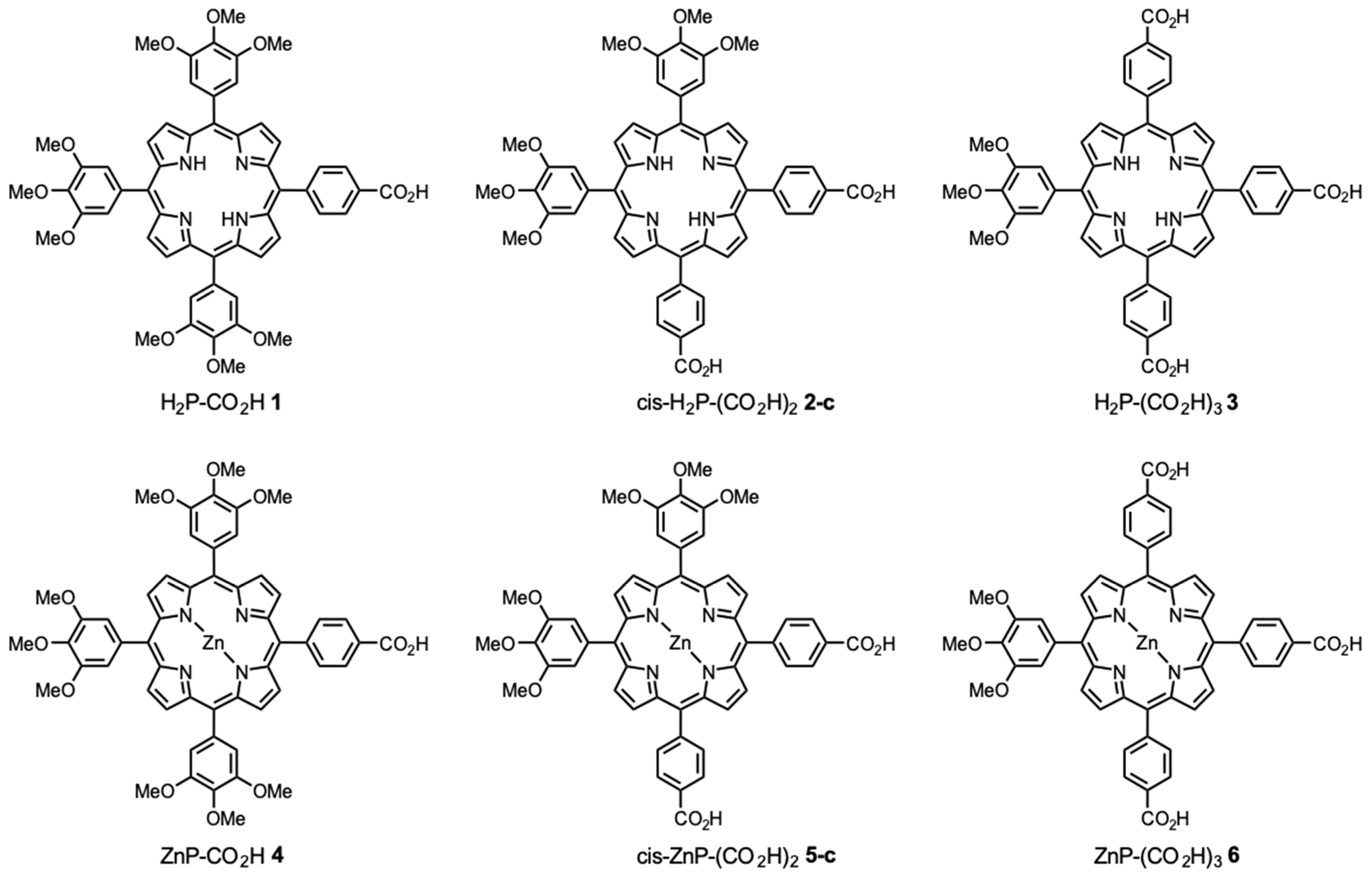
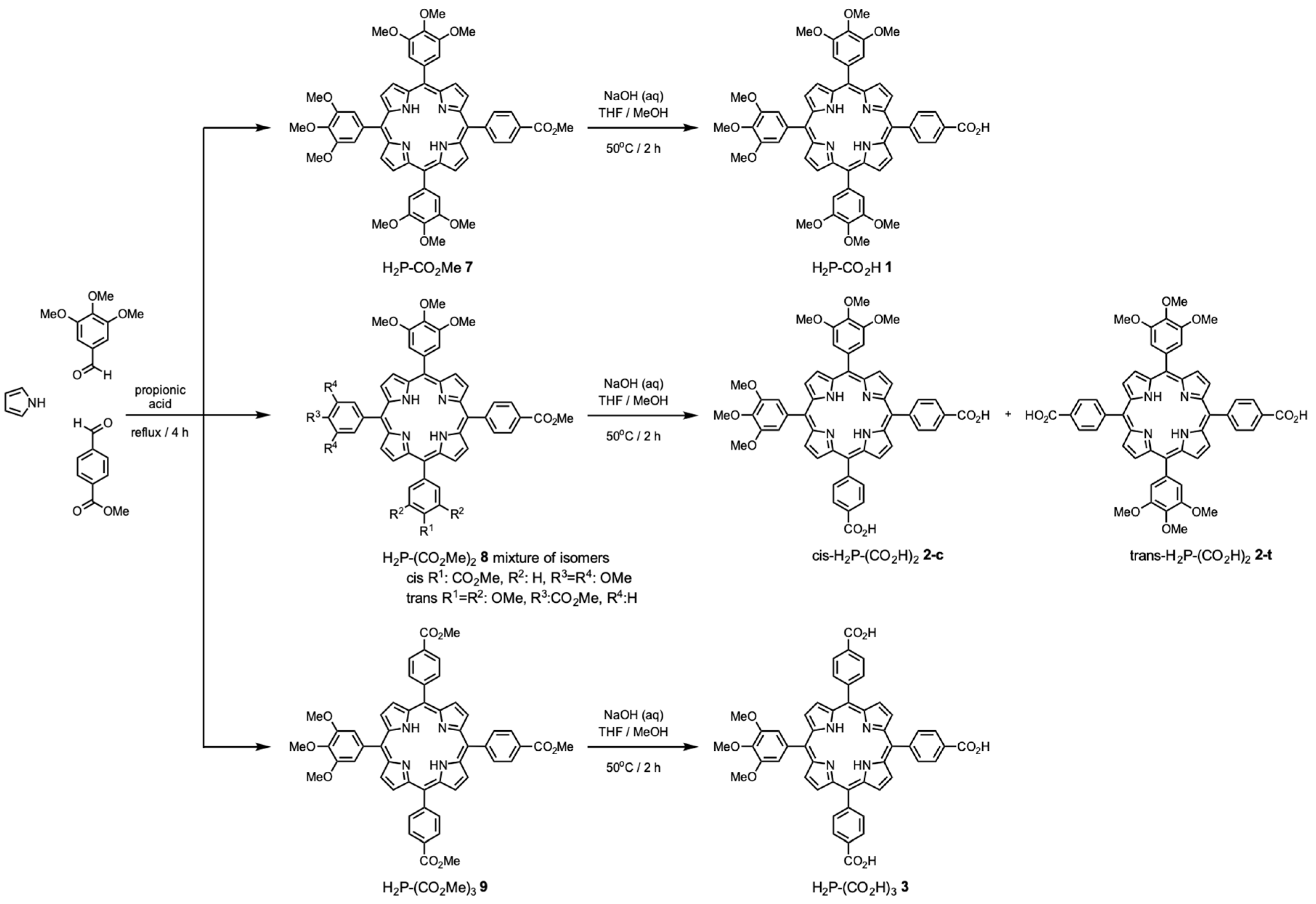
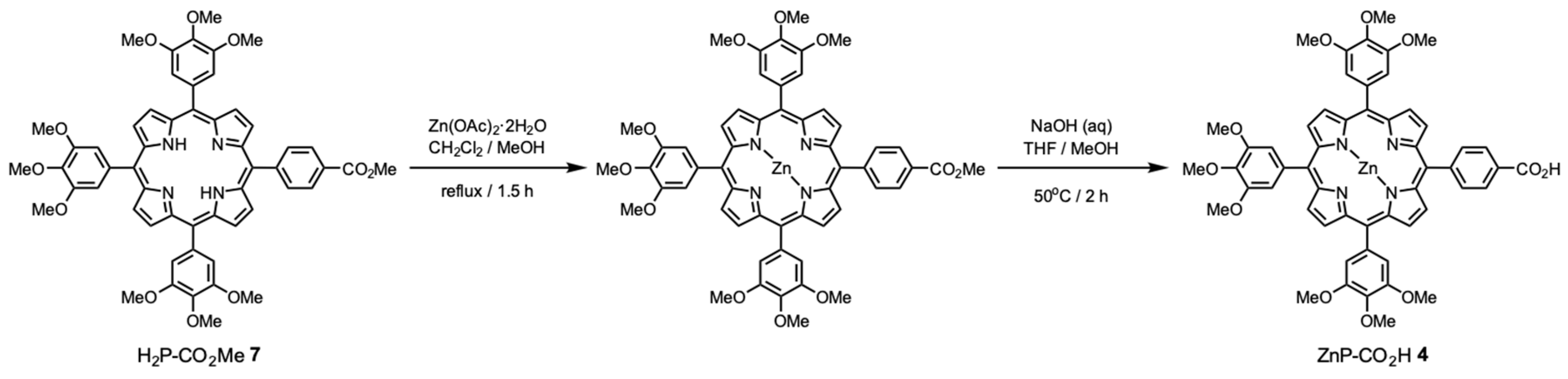
2.1. Synthesis and Characterization of New Compounds

All chemicals were reagent grade, purchased from commercial sources, and were used as received unless otherwise specified. Column chromatography was performed on SiO2 (40–63 μm). TLC plates coated with SiO2 60F254 were visualized under UV light. NMR spectra were acquired on a Bruker AC 300 spectrometer (Bruker, Billerica, MA, USA). UV/Vis spectra were recorded on a Helios Gamma spectrophotometer. Fluorescence spectra were recorded on a Perkin-Elmer LS 55 luminescence spectrometer (PerkinElmer, Waltham, MA, USA). Matrix-assisted laser desorption/ionization time-of-flight (MALDI-TOF) mass spectra were obtained on a Bruker Microflex spectrometer (Bruker, Billerica, MA, USA). Differential pulse voltammetry measurements were performed at 298 K in a conventional three-electrode cell using a m-AUTOLAB type III potentiostat/galvanostat (Metrohm, Herisau, Switzerland). Sample solutions (ca. 0.5 mM) were prepared in deaerated PhCN, containing 0.10 M tetrabutylammonium hexafluorophosphate (TBAPF6) as supporting electrolyte. A glassy carbon (GC) working electrode, an Ag/AgNO3 reference electrode, and a platinum wire counter electrode were used. Ferrocene/ferrocenium was the internal standard for all measurements.

2.1.1. Synthesis of Free-Base Porphyrins H2P-(CO2Me)n 7–9

In a 500 mL round bottom flask equipped with a magnetic stirrer, 3.53 g of 3,4,5-trimethoxybenzaldehyde (18 mmol,) 0.99 g of methyl 4-formylbenzoate (6 mmol) and 1.65 mL of pyrrole (24 mmol) were refluxed for 5 h in propionic acid (250 mL). After cooling at room temperature, the resulting mixture was extracted with dichloromethane several times and, the combined extracts, washed with water and aqueous 4% NaHCO3 solution, dried over MgSO4 and evaporated. The black colored crude compound was purified by silica gel column using hexane/ethylacetate eluent mixtures to get 0.396 g (7%) of 7 H2P-CO2Me, 0.437 g (8%) of a mixture of 8 H2P-(CO2H)2 cis and trans isomers and 0.422 g (8%) of 9 H2P(CO2H)3.
5-(4-methoxycarbonylphenyl)-10,15,20-tris(3,4,5-trimethoxyphenyl)porphyrin (H2P-CO2Me 7).1H NMR (CDCl3: 300 MHz), δ ppm: −2.78 (s, 2H, −NH), 3.97 (s, 18H, m−OCH3), 4.12 (s, 3H, −OCH3) 4.19 (s, 9H, p−OCH3), 7.47 (s, 6H, phenyl H), 8.32 (d, 2H, phenyl H), 8.44 (d, 2H, phenyl H), 8.81 (d, 2H, pyrrole H), 8.98 (d, 6H, pyrrole H). UV-vis (THF) λmax/nm (log Ԑ): 420 (5.64), 515 (4.36), 550 (3.98), 592 (3.74), 650 (3.00). HRMS (MALDI-TOF): m/z calcd, for C55H50N4O11 ([M+]): 942.35, found 942.43.
5,10-bis(4-methoxycarbonylphenyl)-15,20-bis(3,4,5 trimethoxyphenyl)porphyrin (H2P-(CO2Me)2 8, cis/trans mixture).1H NMR (CDCl3: 300 MHz), δ ppm: −2.79 (s, 2H, −NH), 3.97 (s, 12H, m−OCH3), 4.11 (s, 6H, −OCH3) 4.18 (s, 6H, p−OCH3), 7.46 (s, 4H, phenyl H), 8.31 (d, 4H, phenyl H), 8.44 (d, 4H, phenyl H), 8.81 (d, 4H, pyrrole H), 8.97 (d, 4H, pyrrole H). UV-vis (THF) λmax/nm (log Ԑ): 421 (5.58), 515 (4.29), 549 (3.88), 591 (3.68), 649 (3.18). HRMS (MALDI-TOF): m/z calcd, for C54H46N4O10 ([M+]): 910.32, found 910.45.
5,10,15-tris(4-methoxycarbonylphenyl)-20-(3,4,5-trimethoxyphenyl)porphyrin (H2P-(CO2Me)3 9).1H NMR (CDCl3: 300 MHz), δ ppm: −2.80 (s, 2H, −NH), 3.97 (s, 6H, m−OCH3), 4.12 (s, 9H, −OCH3) 4.18 (s, 3H, p−OCH3), 7.46 (s, 2H, phenyl H), 8.31 (d, 2H, phenyl H), 8.43 (d, 2H, phenyl H), 8.81 (d, 2H, pyrrole H), 8.98 (d, 2H, pyrrole H). UV-vis (THF) λmax/nm (log Ԑ): 419 (5.44), 514 (4.13), 550 (3.73), 590 (3.48), 649 (2.30). HRMS (MALDI-TOF): m/z calcd, for C53H42N4O9 ([M+]): 878.30, found 878.64.

2.1.2. Synthesis of Free-Base Porphyrins H2P-(CO2H)n 1–3:

50 mg of free-base porphyrin was dissolved in a mixture of THF/MeOH (20/14 mL) and 6 mL of NaOH 20% aqueous solution were added. The crude was heated for 2 h. After cooling, the reaction crude was then diluted with dichloromethane and washed, first with HCl (1M) and then with water. The organic layer dried over MgSO4 and evaporated. The residue was recrystallized in hexane to get the pure powder.
Column chromatography was conducted for H2P-(CO2H)2 2, to isolate cis and trans isomers (SiO2, chloroform/acetone mixtures as eluents).
5-(4-carboxyphenyl)-10,15,20-tris(3,4,5-trimethoxyphenyl)porphyrin (H2P-CO2H 1). Yield: 95%. 1H NMR (DMSO: 300 MHz), δ ppm: −2.93 (s, 2H, −NH), 3.90 (s, 18H, m−OCH3), 4.00 (s, 9H, p−OCH3), 7.53 (s, 2H, phenyl H), 8.33 (d, 2H, phenyl H), 8.39 (d, 2H, phenyl H), 8.81 (d, 2H, pyrrole H), 8.96 (d, 6H, pyrrole H). UV-vis (THF) λmax/nm (log Ԑ): 420(5.38), 515(4.13), 550(3.70), 592(3.70), 650 (3.30). HRMS (MALDI-TOF) calcd for C54H48N4O11 ([M+]): 928.33, found 928.38.
5,10-bis(4-carboxyphenyl)-15,20-bis(3,4,5 trimethoxyphenyl)porphyrin, trans isomer (trans-H2P-(CO2H)2 2-t). Yield: 23%. 1H NMR (DMSO: 300 MHz), δ ppm: −2.93 (s, 2H, −NH), 3.89 (s, 12H, m−OCH3), 3.99 (s, 6H, p−OCH3), 7.54 (s, 4H, phenyl H), 8.33 (d, 4H, phenyl H), 8.38 (d, 4H, phenyl H), 8.82 (d, 4H, pyrrole H), 8.98 (d, 4H, pyrrole H). UV-vis (THF) λmax/nm (log Ԑ): 420 (5.59), 515 (4.27), 550 (3.93), 592 (3.78), 651(3.65). HRMS (MALDI-TOF): m/z calcd, for C52H42N4O10 ([M+]): 882.29, found 882.518.
5,10-bis(4-carboxyphenyl)-15,20-bis(3,4,5 trimethoxyphenyl)porphyrin, cis isomer (cis-H2P-(CO2H)2 2-c). Yield: 71%. 1H NMR (DMSO: 300 MHz), δ ppm: −2.93 (s, 2H, −NH), 3.90 (s, 12H, m−OCH3), 3.99 (s, 6H, p−OCH3), 7.53 (s, 4H, phenyl H), 8.32 (d, 4H, phenyl H), 8.38 (d, 4H, phenyl H), 8.83 (d, 4H, pyrrole H), 8.98 (d, 4H, pyrrole H). UV-vis (THF) λmax/nm (log Ԑ): 420 (5.59), 515 (4.27), 550 (3.93), 591 (3.78), 649 (3.65). HRMS (MALDI-TOF): m/z calcd, for C52H42N4O10 ([M+]): 882.29, found 882.52.
5,10,15-tris(4-carboxyphenyl)-20-(3,4,5-trimethoxyphenyl)porphyrin (H2P-(CO2H)3 3). Yield: 94%. 1H NMR (DMSO: 300 MHz), δ ppm: −2.93 (s, 2H, −NH), 3.90 (s, 6H, m−OCH3), 3.99 (s, 3H, p−OCH3), 7.55 (s, 2H, phenyl H), 8.35 (d, 6H, phenyl H), 8.38 (d, 6H, phenyl H), 8.85 (d, 6H, pyrrole H), 8.98 (d, 2H, pyrrole H). UV-vis (THF) λmax/nm (log Ԑ): 419(5.52), 515(4.18), 549(3.78), 590(3.54), 649 (3.40). HRMS (MALDI-TOF): m/z calcd, for C50H36N4O9 ([M+]): 836.25, found 836.50.

2.1.3. Synthesis of Zinc Porphyrins ZnP-(CO2H)n 4–6

Free-base porphyrin (7, 8 or 9, 50 mg) and zinc acetate (1:5 mol ratio) were refluxed in dichloromethane and methanol (1:1 ratio, 40 mL each) until free-base porphyrin was completely metalated, checked by TLC and UV-vis absorption spectroscopy. The reaction mixture was then diluted with dichloromethane and washed, first with HCl (1 M) and then with water. The organic layer was collected and, after evaporation of solvent, the crude compound was purified by silica gel column using hexane/ethyl acetate eluent mixtures. Quantitative yields were obtained in all cases and isolated compounds were hydrolized following the same procedure used for free-base porphyrins hydrolisis (see Section 2.1.2).
Column chromatography was conducted for ZnP-(CO2H)2 5 to isolate cis and trans isomers (SiO2, chloroform/acetone mixtures as eluents).
Zinc(II) 5-(4-carboxyphenyl)-10,15,20-tris(3,4,5-trimethoxyphenyl)porphyrinate (ZnP-CO2H 4). Yield: 98%. 1H NMR (DMSO: 300 MHz), δ ppm: 3.90 (s, 18H, m−OCH3), 3.99 (s, 9H, p−OCH3), 7.45 (s, 2H, phenyl H), 8.29 (d, 2H, phenyl H), 8.37 (d, 2H, phenyl H), 8.75 (d, 2H, pyrrole H), 8.90 (d, 6H, pyrrole H). UV-vis (THF) λmax/nm (log Ԑ): 426 (5.63), 557 (4.20), 597 (3.65). HRMS (MALDI-TOF) calcd for C54H46N4O11 ([M+]): 990.25, found 989.22.
Zinc(II) 5,10-bis(4-carboxyphenyl)-15,20-bis(3,4,5-trimethoxyphenyl)porphyrinate, trans isomer (trans-ZnP-(CO2H)2 5-t). Yield: 20%. 1H NMR (DMSO: 300 MHz), δ ppm: 3.89 (s, 12H, m−OCH3), 3.98 (s, 6H, p−OCH3), 7.46 (s, 4H, phenyl H), 8.23 (d, 4H, phenyl H), 8.35 (d, 4H, phenyl H), 8.76 (d, 4H, pyrrole H), 8.91 (d, 4H, pyrrole H). HRMS (MALDI-TOF): m/z calcd, for C52H40N4O10Zn ([M+]): 944.20, found 943.45.
Zinc (II) 5,10-bis(4-methoxycarbonylphenyl)-15,20-bis(3,4,5-trimethoxyphenyl)porphyrinate, cis isomer (cis-ZnP-(CO2H)2 5-c). Yield: 69%. 1H NMR (DMSO: 300 MHz), δ ppm: 3.89 (s, 12H, m−OCH3), 3.98 (s, 6H, p−OCH3), 7.45 (s, 4H, phenyl H), 8.23 (d, 4H, phenyl H), 8.34 (d, 4H, phenyl H), 8.76 (d, 4H, pyrrole H), 8.91 (d, 4H, pyrrole H). UV-vis (THF) λmax/nm (log Ԑ): 426 (5.56), 557 (4.29), 597 (3.80). HRMS (MALDI-TOF): m/z calcd, for C52H40N4O10Zn ([M+]): 944.20, found 943.48.
Zinc(II) 5,10,15-tris(4-carboxyphenyl)-20-(3,4,5-trimethoxyphenyl)porphyrinate (ZnP-(CO2H)3 6). Yield: 98%. 1H NMR (DMSO: 300 MHz), δ ppm: 3.90 (s, 6H, m−OCH3), 3.99 (s, 3H, p−OCH3), 7.47 (s, 2H, phenyl H), 8.29 (d, 6H, phenyl H), 8.37 (d, 6H, phenyl H), 8.78 (d, 6H, pyrrole H), 8.94 (d, 2H, pyrrole H). UV-vis (THF) λmax/nm (log Ԑ): 426 (5.70), 557 (4.33), 598 (3.89). HRMS (MALDI-TOF): m/z calcd, for C50H34N4O9Zn ([M+]): 898.16, found 897.40.

2.2. Device Preparation

Double-layered nanoporous TiO2 photoanodes were prepared coating pastes of anatase TiO2 nanoparticles having two different diameters, 20 nm (Dyesol’s 90 T) and 400 nm (Dyesol’s WER2-O), onto TiCl4 treated FTO glass plates (TEC 15 A, 2.2 mm, Xop Glass), by repetitive screen printing to obtain the required thickness. These electrodes were gradually heated under a programmed flow: at 370 °C for 10 min and 450 °C for 10 min. Their apparent surface area was 0.16 cm2 (0.4 cm × 0.4 cm), and revealed a total thickness of 8–10 μm, containing a 3–4 μm scattering layer. The TiO2 electrodes were treated again with TiCl4 under 70 °C for 30 min and sintered at 500 °C for 30 min, before they were dipped into dye solution. The nanocrystalline TiO2 films were immersed into 5 mM dye solutions, without any other additives, i.e. co-adsorbents, and kept at RT for 20 h. Finally, dye adsorbed TiO2 photoanodes and thermally platinized and drilled FTO counter electrodes (TEC 8 A, 3 mm, Xop Glass), were assembled into sandwich type cells, separated by a 30 μm thick hot-melt gasket (Surlyn, Dupont), and sealed by heating. An electrolyte solution (0.1 M LiI, 0.03 M I2, 0.5 M 4-tert-butylpyridine, 0.1 M guanidinium thiocyanate, 1 M 1-butyl-3-methylimidazolium iodide in acetonitrile/valeronitrile 85:15 v/v) was introduced in the assembled devices. A series of three devices with each dye were prepared and their photovoltaic performance measured. The values described are, in all cases, the best obtained, with no significant differences between devices sensitized with the same dye, which ensures the reproducibility and consistency of the results.

2.3. Photovoltaic Characterization

An ABET 150W xenon light source equipped with an AM 1.5 G correcting filter was employed. The light intensity was adjusted to 100 mW/cm2 (the equivalent of 1 sun), prior to every measurement, using a calibrated photovoltaic reference cell (15150, ABET Technologies). The applied potential and cell current were registered with a Keithley 2401 low voltage digital sourcemeter. The incident photon-to-current conversion efficiency (IPCE) was measured as a function of wavelength from 400 to 800 nm by using an IPCE-DC system (Lasing SA).

3. Results and Discussion

3.1. Synthesis of New Compounds

Free base porphyrin compounds H2P-CO2H 1, H2P-(CO2H)2 2 (cis and trans) and H2P-(CO2H)3 3 were prepared through a two-step synthetic sequence, as it is described in Scheme 1. First, methyl ester derivatives (79) were obtained as pure compounds, following the traditional Adler-Longo method [24], by reacting a 4:3:1 mixture of pyrrole, 3,4,5-trimethoxybenzaldehyde and methyl 4-formylbenzoate in propionic acid. In a second step, methyl ester groups were hydrolyzed by heating in an aqueous base solution affording, in almost quantitative yields, free-base porphyrins with one, two and three carboxylic groups (13). It is worth to note that the hydrolysis of H2P-(CO2Me)2 8, mixture of cis and trans stereoisomers, gave a new mixture which could be resolved into its components, cis-H2P-(CO2H)2 2-c and trans-H2P-(CO2H)2 2-t, through standard column chromatography.
Finally, in order to obtain Zn porphyrins ZnP-CO2H 4, ZnP-(CO2H)2 5 (cis and trans) and ZnP-(CO2H)3 6, methyl ester precursors (79) were, first metallated in refluxing dichloromethane/methanol mixture, in presence of a zinc acetate excess, and, without isolation, hydrolyzed, following the procedure previously used in the synthesis of H2P-(CO2H)n 13. An example of the synthetic sequence performed (synthesis of ZnP-CO2H 4) is shown in Scheme 2. As it occurred with H2P-(CO2H)2 2 cis and trans isomers, the metalation of 8 (mixture of isomers), followed by basic hydrolysis, afforded a new mixture of compounds which could be separated into its components, ZnP-(CO2H)2 5 cis and trans, through standard column chromatography.
All synthesized compounds 19 (Figures S1, S4, S10, S13, S16, S19, S22, S25, S28 and S31 were characterized through common techniques, such 1H NMR and UV-vis spectroscopies and HR-MS (MALDI TOF) mass spectrometry. In this context, the 1H NMR signals obtained for H2P-(CO2H)n 13 (Figures S2, S5, S7, S8 and S11), ZnP-(CO2H)n 46 (Figures S14, S17, S20, and S23) and H2P-(CO2Me)n 79 (Figures S26, S29, and S32) showed similar chemical displacements, but displayed different integral values for the signals corresponding to the phenyl and methoxy groups. On the other hand, HR MS gave, in all cases, a single peak with a m/z ratio that exactly matched the calculated one (Figures S3, S6, S9, S12, S15; S18, S21, S24, S27, S30 and S33).

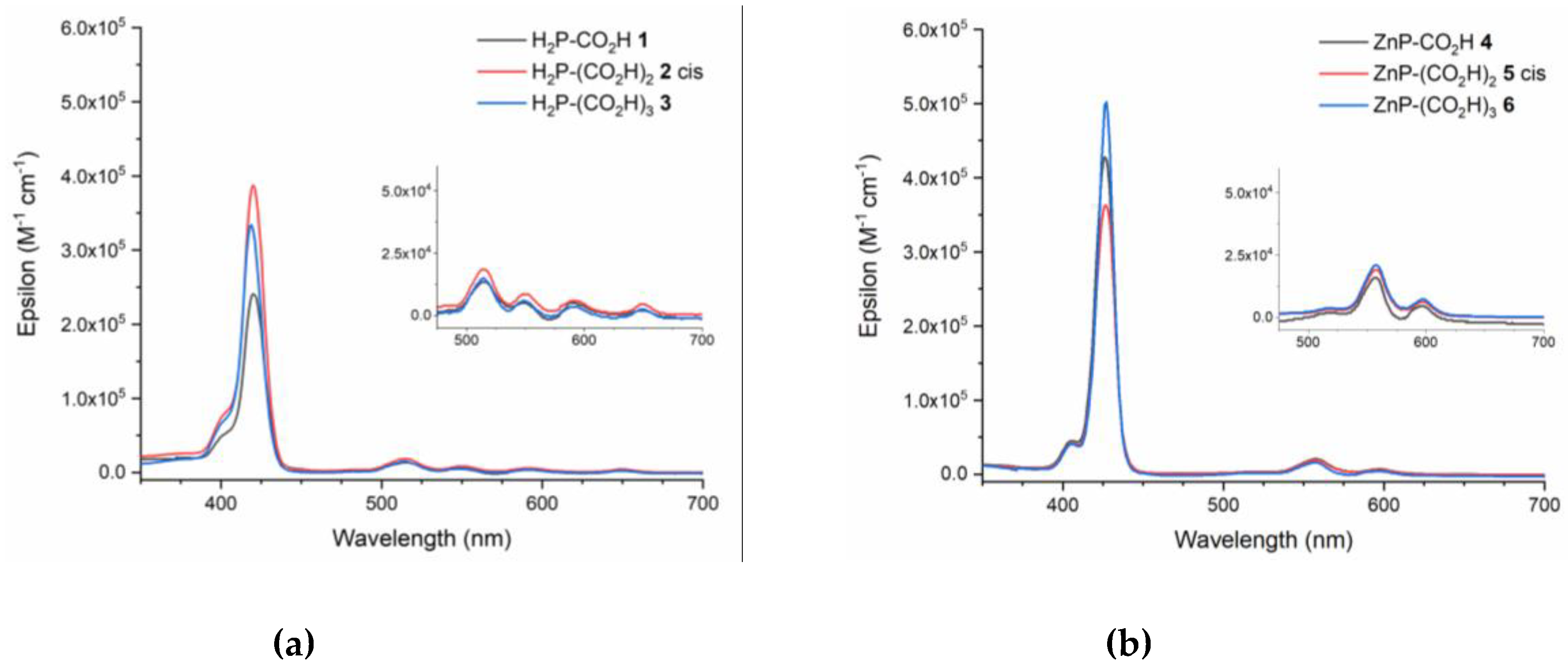
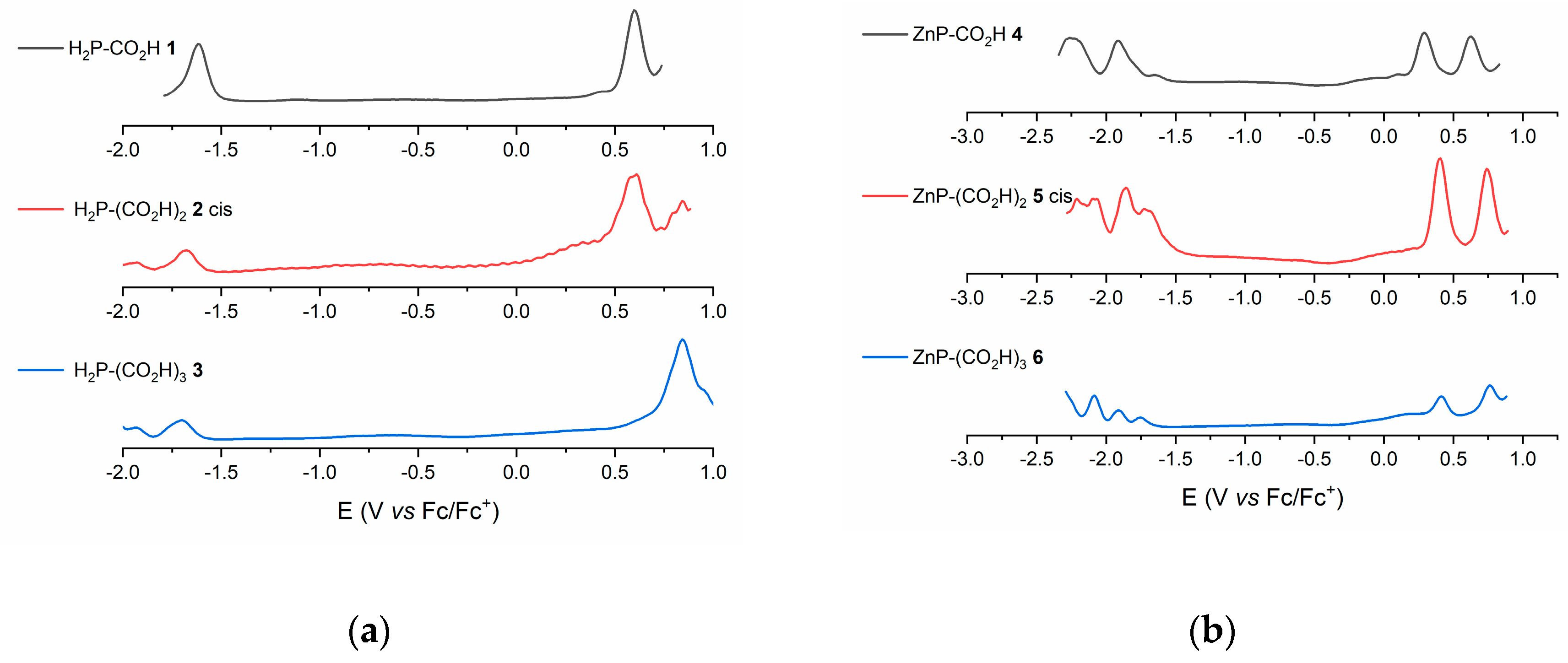
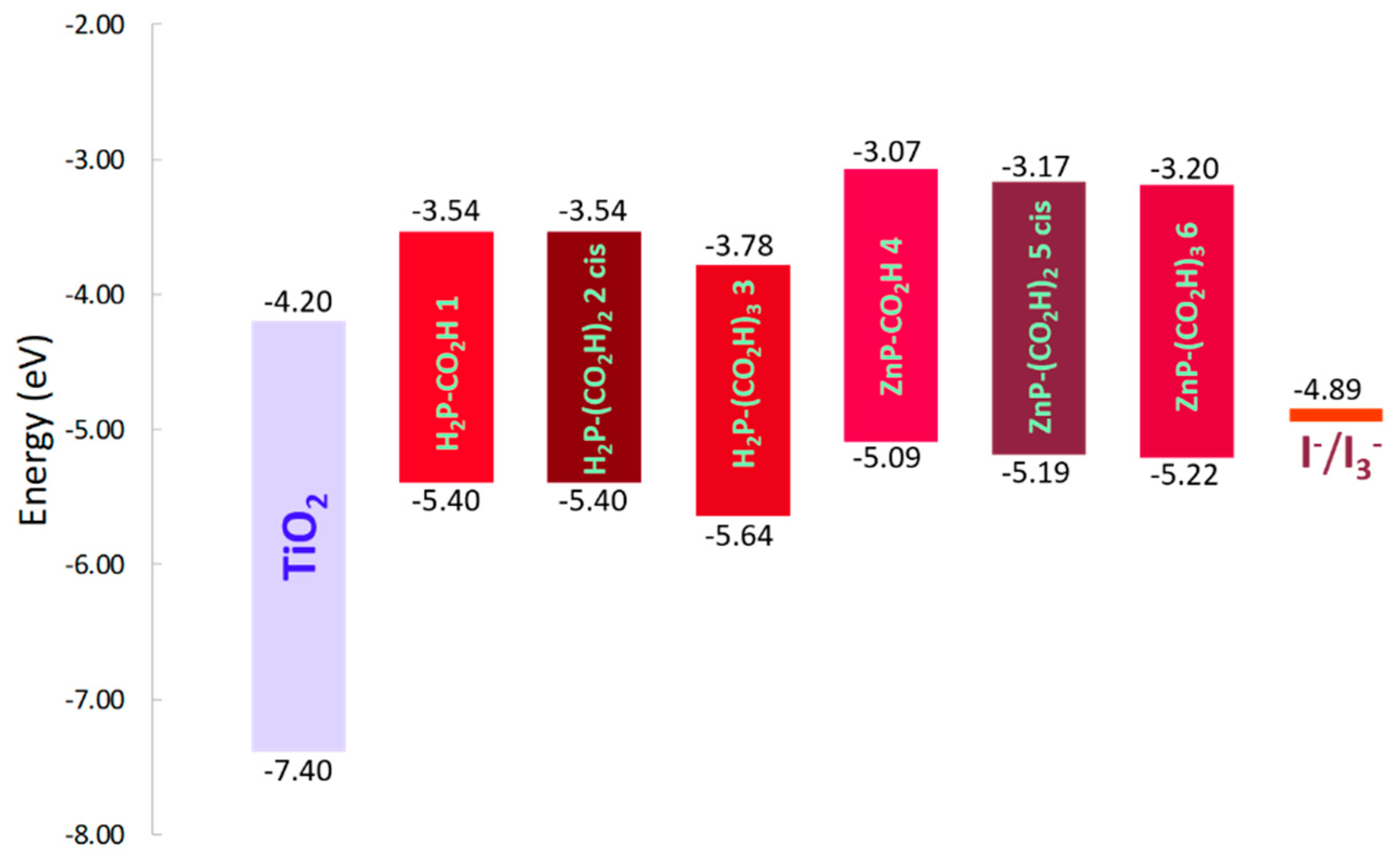
3.2. Optical and Electrochemical Properties

Free porphyrins 1, 2 cis, and 3, and zinc derivatives, 4, 5 cis, and 6, were evaluated as sensitizers for DSSC devices. It must be stated that trans isomers of compounds 2 and 5 could not be evaluated, because of their reduced solubility which prevented their optical and electrochemical characterisation.
The UV-vis absorption spectra of all dyes show typical features of porphyrin compounds (Figure 2). While H2P 13 present a strong absorption band at 420 nm (S0→S2, Soret band) and four weak transitions to the first excited state between 500 and 680 nm (S0→S1, Q bands), ZnP 46 exhibit, a 6–7 nm red-shifted Soret band and only two Q bands, which are located in the 550–650 nm area. These spectral changes, upon metalation of the macrocycle, are probably due to the increased symmetry of the porphyrin core, moving from D2h to D4h. It is also worth to note that the introduction of a zinc atom in the porphyrin cavity, causes a π-π interaction between the metal pπ orbital and the porphyrin π system. According to the four orbital model of porphyrins [25], the electronic density on the meso positions and the pyrrolic nitrogen atoms is large, so the energy of a2u and eg orbitals is, therefore, influenced by both the metal ion and the substituents introduced at the meso positions. Regarding to the molar extinction coefficients, zinc derivatives show somehow higher values than the metal free ones. It is also remarkable that within a series (ZnP/H2P), variations in the coefficients are minimal, and are attributed to differences in solubility, due to number of carboxy groups. Finally, internal conversion between S2 and S1 is rapid, so fluorescence is only detected from S1. Taking into account that intensity of Q bands is weak, transition energies cannot be accurately estimated from the intersection of normalized absorption and emission spectra [26,27], so the optical band gap (Egopt) was here calculated using the equation (1) where λedge is the onset value of the absorption spectrum in the direction of longer wavelengths [28].
E g opt = 1240 λ edge eV
Peak position (λabs), molar absorption coefficients (ε) of Soret and Q bands, onset values (λedge) and estimated optical band gap (Egopt) of porphyrin dyes are listed in Table 1.
Electrochemical measurements were performed for H2P 13 and ZnP 46, registering differential pulse voltammograms in benzonitrile solution (Figure 3). All measured dyes exhibit simple, clear and sharp waves in the anodic part, very different from those in the cathodic area. This can be probably due to the genuine electron-donor character of porphyrin compounds and, particularly, for these studied 3,4,5-trimethoxyphenyl–substituted porphyrins. Also, this observation provides evidence for extensive changes in the electronic structure of the studied compounds, induced by one electron reduction of the aromatic macrocycles. In this context, and taking into account only oxidation processes, H2P 13 are more resistant to oxidation than ZnP 46. On the other hand, as a general tendency, oxidation potentials increase with the number of carboxy groups. Due to the increase in the number of carboxy groups, which is associated with a concomitant decrease in the number of trimethoxyphenyl moieties, the resonance interactions between the a2u orbital and the porphyrin π system become weaker, thus favoring the stabilization of that orbital. The decreased oxidation potential of the metalloporphyrins, compared to that of the free base analogues, seems to be due to destabilization of a2u orbitals of the former, probably caused by π resonance interactions between the metal pπ orbital, porphyrin a2u orbital and the aryl group π system [29].
Spectral and electrochemical properties allow to determine the electron injection and dye regeneration possibility during DSSC performance. From Eox potential values, referenced to Fc/Fc+ pair, (Table 2) HOMO energy level for all dyes can be easily calculated, using the Equation (2).
E HOMO ( eV ) = 4.8 E ox ( V   vs   Fc / Fc + )
These values, combined with the previously estimated optical band gap (Egopt), and values of conduction band of TiO2 (−4.2 eV) [30] and I/I3 redox potential (−4.89 eV) [31,32], allow to sketch an energy diagram representing HOMO and LUMO levels for all studied dyes (Figure 4). At this point, it is important to mention that the determination of the LUMO level, using the EHOMO obtained from electrochemical measurements and estimated Egopt, is a very useful approximation in the case that both Eox and Ered values cannot be accurately extracted from electrochemical measurements. As can be seen, LUMO energy levels are, in all cases, higher than TiO2 conduction band (TiO2 CB), fundamental requisite to make the electron injection thermodynamically feasible, while HOMO levels are, always, lower than I/I3 redox potential, making possible the regeneration of the oxidized dye.

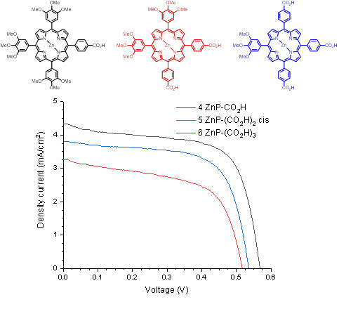
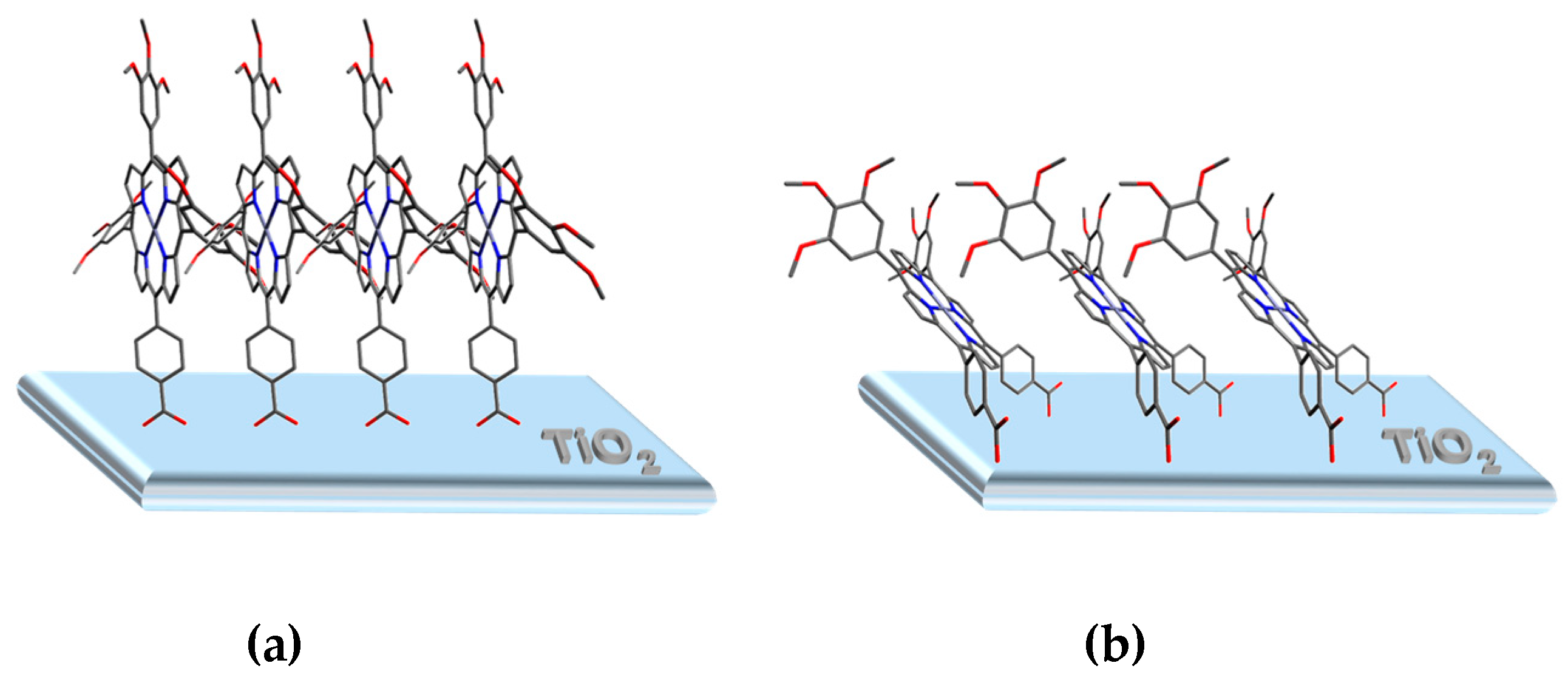
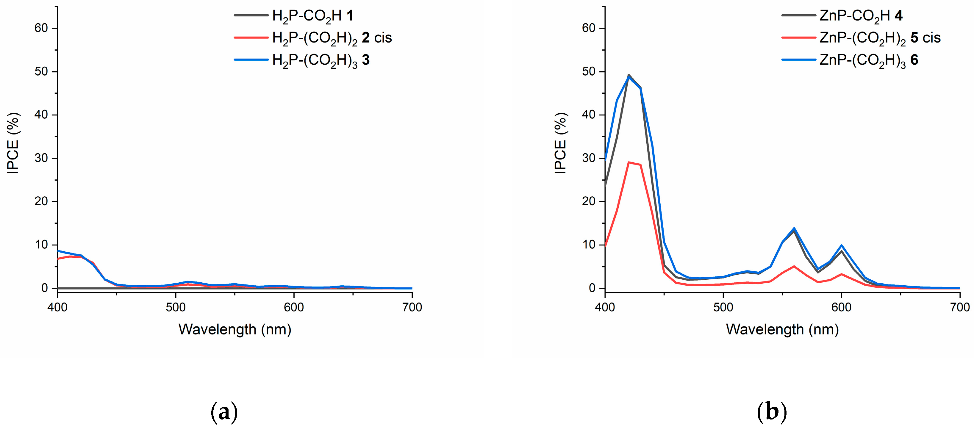
3.3. Preparation of Devices and Photovoltaic Characterization

Dye sensitized solar cells were prepared following a standard procedure, using double layered screen-printed TiO2 photoanodes, platinum casted counter-electrodes, and liquid electrolyte containing 0.05 M LiI, 0.03 M I2, 0.5 M 4-tertbutylpyridine (TBP), 0.1 M guanidinium thiocyanate (GNCS), 1 M 1-butyl-3-methylimidazolium iodide (BMII) in acetonitrile/valeronitrile (85:15 v/v). Once prepared, efficiencies of all devices were evaluated under standard Air Mass 1.5 global (AM1.5G) solar irradiation, constructing J/V curves, and analyzing incident photon to current conversion efficiencies (IPCE).
All employed dyes gave efficient photoanode sensitization without any other additive (20 h dipping in 5 mM dye ethanol solution), qualitatively appreciated through a deep anode coloration. At this point we considered the use of co-adsorbents to improve the performance, particularly chenodeoxycolic acid (Cheno). In porphyrin and phthalocyanine sensitized solar cells, Cheno is commonly used as co-adsorbent and, directly incorporated in sensitizing solutions, improves both Jsc and Voc parameters, thus leading to better device efficiencies, so we prepared sensitizing solutions of our dyes, incorporating Cheno as co-adsorbent. Unfortunately, only scarce sensitization occurred in all cases, obtaining, after dipping, soft-colored photoanodes unable to be efficiently photoexcitated. In this case, an unbalanced competency between dye and Cheno molecules seems to occur, hampering the anchorage of sensitizing units onto TiO2 surface.
Figure 5 shows J/V curves for devices sensitized with H2P and ZnP derivatives, and Table 3 resumes the photovoltaic parameters, short-circuit current (Jsc), open circuit voltage (Voc) and fill factor (FF), reflecting much better efficiencies for the zinc compounds. The reason for this difference must be found in the Zn+2 porphyrin metallic core, a closed shell ion with empty coordination sites, which allow an efficient and rapid injection of photoexcited porphyrin electrons to TiO2 conduction band, acting as mediator for electron transfer from I/I3 to the a2u orbital of the porphyrinsensitizer. It is worth to note that the obtained efficiency for device sensitized with ZnP-CO2H 4 is up to 1.62%, with Jsc value of 4.34 mA/cm2, Voc of 0.57 V and FF of 0.65, better than that previously reported for the same compound, (1.06%) [33], demonstrating the convenience of our device preparation protocol. On the other hand, ZnP derivatives with two (cis-ZnP-(CO2H)2 5-c) and three (ZnP-(CO2H)3 6) carboxylic acid anchoring groups showed lower results, due a combination of both electronic and structural features. It is well known that efficient dyes usually present the so called push–pull effect, thus facilitating the injection to the TiO2 conduction band [34]. ZnP-CO2H 4 shows strong push pull directionality, thanks to the already mentioned electron-acceptor character of the anchoring group and the presence of three electron-donor trimethoxyphenyl substituents in the meso positions. A lesser push pull effect can be found in cis-ZnP-(CO2H)2 5-c and ZnP-(CO2H)3 6. On the other hand, more than one anchoring group means a better anchorage to TiO2, but not necessarily means better performance. Anchored dyes in such way could adopt a flat binding position (“face-to-face”, Figure 6a) referred to the TiO2 surface, offering a lower coverage degree than it does in a perpendicular/vertical fashion (“edge-to-face”, Figure 6b) [35,36]. This is what probably happens, looking to the photovoltaic parameters extracted from J/V curves. The Jsc value for ZnP-CO2H 4 sensitized devices, compared to those sensitized with cis-ZnP-(CO2H)2 5-c and ZnP-(CO2H)3 6 (Table 3), indicates a higher photogenerated current, due to a more compact coverage of the semiconductor surface by the dye. In this context, high values of Voc in ZnP-CO2H 4 sensitized devices (Table 3), also confirm this hypothesis. High Voc values are indicative of non-aggregated molecules and, in this case, also protection of the central metal core. If ZnP-CO2H 4 molecules are covering the TiO2 surface in an “edge-to-face” manner, π-π stacking phenomena seems unlikely to happen between adjacent molecules, due to the necessary non-coplanar position (related to the porphyrin flat structure) of bulky meso-trimetoxyphenyl groups. This results in an effective protection of the porphyrin central metal core, avoiding early recombination processes with the electrolyte, thus affording better Voc values. Same reasoning could be applied to devices sensitized with H2P derivatives 13 but, in this case, the lack of metal ion in the dye becomes crucial. In absence of such mediator, the injection step is slowed down, and early recombination processes are then favored. Interestingly, and opposite to what happens with ZnP 46 sensitized devices, structural features of free-base dyes seem to gain weight vs electronic characteristics (more than one binding group vs push-pull effect). cis-H2P-(CO2H)2 2-c and H2P-(CO2H)3 3 sensitized devices show better Jsc values than those of H2P-(CO2H) 1 (Table 3). This fact indicates that the chromophore is closer to the semiconductor surface, balancing out the absence of metal ion. Furthermore, the number of sterically demanding trimethoxyphenyl groups of the dye, is also reflected in Voc values, higher in the case of cis-H2P-(CO2H)2 2-c sensitized devices. The presence of two bulky trimethoxyphenyl groups at the meso positions, and only one in the case of H2P-(CO2H)3 3, partially avoids π-π stacking phenomena between adjacent adsorbed molecules.
Finally, IPCE measurements were made for all devices, showing maxima of photogenerated current in wavelengths which match the absorption profile of employed sensitizers (Figure 7). As expected, higher performances were obtained for ZnP derivatives 46, with maxima at 420, 560 and 600 nm and percentages of 50%, 14%, and 9% respectively in the case of ZnP-CO2H 4. These results confirm the convenience of introducing just one anchoring place in carboxy ZnP-based sensitizers for DSSCs.

4. Conclusions

A series of unsymmetric porphyrin compounds, free-base [H2P-(CO2H)n 13] and Zn metallated [ZnP-(CO2H)n 46], with one, two or three carboxyphenyl anchoring groups, were synthesized, characterized and used as sensitizers in TiO2-based DSSC devices. The comparison of their performances shows the utility of these compounds for this use, reflecting that ZnP-(CO2H)n 46 sensitized solar cells offer better efficiencies, compared to those sensitized with H2P-(CO2H)n 13. This is due to the presence of a zinc ion in the porphyrin inner cavity, acting as electronic mediator in the injection step. The observed order of efficiency for the zinc complexes, i.e. ZnP-CO2H 4 > ZnP-(CO2H)3 6 > cis-ZnP-(CO2H)2, 5-c is in agreement with a rapid injection of the photoexcited electrons to the TiO2 conduction band, where electronic characteristics of the dye prevail over its structural features. On the other hand, the observed order of efficiency for free-base dyes, i.e., cis-H2P-(CO2H)2 2-c > (H2P-(CO2H)3 3 > H2P-CO2H 1, agrees with the absence of a metallic mediator, slowing down the injection step and making structural features of the dye to gain prominence over its electronic characteristics.

Supplementary Materials

The following are available online at https://www.mdpi.com/1996-1944/12/4/650/s1, Figure S1: Molecular structure of H2P-CO2H 1, Figure S2: 1H-NMR (CDCl3) H2P-CO2H 1, Figure S3: HR-MS (MALDI-TOF) spectrum of H2P-CO2H 1, Figure S4: Molecular structure of cis-H2P-(CO2H)2 2-c, Figure S5: 1H-NMR (CDCl3) of cis-H2P-(CO2H)2 2-c, Figure S6: HR-MS (MA LDI-TOF) spectrum of cis-H2P-(CO2H)2 2-c, Figure S7: Molecular structure of trans-H2P-(CO2H)2 2-t, Figure S8: 1H-NMR (CDCl3) of trans-H2P-(CO2H)2 2-t, Figure S9: HR-MS (MALDI-TOF) spectrum of trans-H2P-(CO2H)2 2-t, Figure S10: Molecular structure of H2P-(CO2H)3 3, Figure S11: 1H-NMR (CDCl3) of H2P-(CO2H)3 3, Figure S12: HR-MS (MALDI-TOF) spectrum of H2P-(CO2H)3 3, Figure S13: Molecular structure of ZnP-CO2H 4, Figure S14: 1H-NMR (CDCl3) of ZnP-CO2H 4, Figure S15: HR-MS (MALDI-TOF) spectrum of ZnP-CO2H 4, Figure S16: Molecular structure of cis-ZnP-(CO2H)2 5-c, Figure S17: 1H-NMR (CDCl3) of cis-ZnP-(CO2H)2 5-c, Figure S18: HR-MS (MALDI-TOF) spectrum of cis-ZnP-(CO2H)2 5-c, Figure S19: Molecular structure of trans-ZnP-(CO2H)2 5-t, Figure S20: 1H-NMR (CDCl3) of trans-ZnP-(CO2H)2 5-t, Figure S21: HR-MS (MALDI-TOF) spectrum of of trans-ZnP-(CO2H)2 5-t, Figure S22: Molecular structure of ZnP-(CO2H)3 6, Figure S23: 1H-NMR (CDCl3) of ZnP-(CO2H)3 6, Figure S24: HR-MS (MALDI-TOF) spectrum of of ZnP-(CO2H)3 6, Figure S25: Molecular structure of H2P-CO2Me 7, Figure S26: 1H-NMR (CDCl3) of H2P-CO2Me 7, Figure S27: HR-MS (MALDI-TOF) spectrum of H2P-CO2Me 7, Figure S28: Molecular structure of H2P-(CO2Me)2 8 mixture of isomers, Figure S29: 1H-NMR (CDCl3) of H2P-(CO2Me)2 8 mixture of isomers, Figure S30: HR-MS (MALDI-TOF) spectrum of H2P-(CO2Me)2 8 mixture of isomers, Figure S31: Molecular structure of H2P-(CO2Me)3 9, Figure S32: 1H-NMR (CDCl3) of H2P-(CO2Me)3 9, Figure S33: HR-MS (MALDI-TOF) spectrum of H2P-(CO2Me)3 9.

Author Contributions

A.S.-S. directed the research. The project was initially proposed by S.Z., R.N. performed the experimental work and characterized all compounds, materials and devices. R.N., L.M.-G., F.F.-L., S.Z., and A.S.-S. wrote the manuscript.

Funding

Support from the Ministerio de Economía Industria y Competitividad of Spain (CTQ2017-87102-R) is gratefully acknowledged.

Conflicts of Interest

The authors declare no conflict of interest.

References

  1. Kundu, S.; Patra, A. Nanoscale Strategies for Light Harvesting. Chem. Rev. 2017, 117, 712–757. [Google Scholar] [CrossRef]
  2. Zhang, J.; Wang, J.; Long, S.; Peh, S.B.; Dong, J.; Wang, Y.; Karmakar, A.; Yuan, Y.D.; Cheng, Y.; Zhao, D. Luminescent Metal–Organic Frameworks for the Detection and Discrimination of o-Xylene from Xylene Isomers. Inorg. Chem. 2018, 57, 13631–13639. [Google Scholar] [CrossRef]
  3. Acherar, S.; Colombeau, L.; Frochot, C.; Vanderesse, R. Synthesis of Porphyrin, Chlorin and Phthalocyanine Derivatives by Azide-Alkyne Click Chemistry. Curr. Med. Chem. 2015, 22, 3217–3254. [Google Scholar] [CrossRef] [PubMed]
  4. Stulz, E. Nanoarchitectonics with Porphyrin Functionalized DNA. Acc. Chem. Res. 2017, 50, 823–831. [Google Scholar] [CrossRef] [PubMed]
  5. Mahmood, A.; Hu, J.-Y.; Xiao, B.; Tang, A.; Wang, X.; Zhou, E. Recent progress in porphyrin-based materials for organic solar cells. J. Mater. Chem. A 2018, 6, 16769–16797. [Google Scholar] [CrossRef]
  6. Song, H.; Liu, Q.; Xie, Y. Porphyrin-sensitized solar cells: Systematic molecular optimization, coadsorption and cosensitization. Chem. Commun. 2018, 54, 1811–1824. [Google Scholar] [CrossRef] [PubMed]
  7. Di Carlo, G.; Biroli, A.O.; Tessore, F.; Caramori, S.; Pizzotti, M. β-Substituted Zn II porphyrins as dyes for DSSC: A possible approach to photovoltaic windows. Coord. Chem. Rev. 2018, 358, 153–177. [Google Scholar] [CrossRef]
  8. Birel, Ö.; Nadeem, S.; Duman, H. Porphyrin-Based Dye-Sensitized Solar Cells (DSSCs): A Review. J. Fluoresc. 2017, 27, 1075–1085. [Google Scholar] [CrossRef] [PubMed]
  9. Ladomenou, K.; Kitsopoulos, T.N.; Sharma, G.D.; Coutsolelos, A.G. The importance of various anchoring groups attached on porphyrins as potential dyes for DSSC applications. RSC Adv. 2014, 4, 21379–21404. [Google Scholar] [CrossRef]
  10. Santos, T.D.; Morandeira, A.; Koops, S.; Mozer, A.J.; Tsekouras, G.; Dong, Y.; Wagner, P.; Wallace, G.; Earles, J.C.; Gordon, K.C.; et al. Injection Limitations in a Series of Porphyrin Dye-Sensitized Solar Cells. J. Phys. Chem. C 2010, 114, 3276–3279. [Google Scholar] [CrossRef]
  11. Higashino, T.; Sugiura, K.; Tsuji, Y.; Nimura, S.; Ito, S.; Imahori, H. A Push–Pull Porphyrin Dimer with Multiple Electron-donating Groups for Dye-sensitized Solar Cells: Excellent Light-harvesting in Near-infrared Region. Chem. Lett. 2016, 45, 1126–1128. [Google Scholar] [CrossRef] [Green Version]
  12. Chaudhri, N.; Sawhney, N.; Madhusudhan, B.; Raghav, A.; Sankar, M.; Satapathi, S. Effect of functional groups on sensitization of dye-sensitized solar cells (DSSCs) using free base porphyrins. J. Porphyr. Phthalocyanines 2017, 21, 222–230. [Google Scholar] [CrossRef]
  13. Xiang, H.; Fan, W.; Li, J.H.; Li, T.; Robertson, N.; Song, X.; Wu, W.; Wang, Z.; Zhu, W.; Tian, H. High Performance Porphyrin-Based Dye-Sensitized Solar Cells with Iodine and Cobalt Redox Shuttles. ChemSusChem 2017, 10, 938–945. [Google Scholar] [CrossRef] [PubMed]
  14. Parsa, Z.; Naghavi, S.S.; Safari, N. Designing Push–Pull Porphyrins for Efficient Dye-Sensitized Solar Cells. J. Phys. Chem. A 2018, 122, 5870–5877. [Google Scholar] [CrossRef] [PubMed]
  15. Martínez-Díaz, M.V.; de la Torre, G.; Torres, T. Lighting porphyrins and phthalocyanines for molecular photovoltaics. Chem. Commun. 2010, 46, 7090. [Google Scholar] [CrossRef] [PubMed]
  16. Reddy, K.S.K.; Liu, Y.-C.; Chou, H.-H.; Kala, K.; Wei, T.-C.; Yeh, C.-Y. Synthesis and Characterization of Novel β-Bis(N,N-diarylamino)-Substituted Porphyrin for Dye-Sensitized Solar Cells under 1 sun and Dim Light Conditions. ACS Appl. Mater. Interfaces 2018, 10, 39970–39982. [Google Scholar] [CrossRef]
  17. Wu, S.-L.; Lu, H.-P.; Yu, H.-T.; Chuang, S.-H.; Chiu, C.-L.; Lee, C.-W.; Diau, E.W.-G.; Yeh, C.-Y. Design and characterization of porphyrin sensitizers with a push-pull framework for highly efficient dye-sensitized solar cells. Energy Environ. Sci. 2010, 3, 949–955. [Google Scholar] [CrossRef]
  18. Imahori, H.; Matsubara, Y.; Iijima, H.; Umeyama, T.; Matano, Y.; Ito, S.; Niemi, M.; Tkachenko, N.V.; Lemmetyinen, H. Effects of meso-Diarylamino Group of Porphyrins as Sensitizers in Dye-Sensitized Solar Cells on Optical, Electrochemical, and Photovoltaic Properties. J. Phys. Chem. C 2010, 114, 10656–10665. [Google Scholar] [CrossRef]
  19. Sirithip, K.; Prachumrak, N.; Rattanawan, R.; Keawin, T.; Sudyoadsuk, T.; Namuangruk, S.; Jungsuttiwong, S.; Promarak, V. Zinc–Porphyrin Dyes with Different meso-Aryl Substituents for Dye-Sensitized Solar Cells: Experimental and Theoretical Studies. Chem. Asian J. 2015, 10, 882–893. [Google Scholar] [CrossRef]
  20. Keawin, T.; Tarsang, R.; Sirithip, K.; Prachumrak, N.; Sudyoadsuk, T.; Namuangruk, S.; Roncali, J.; Kungwan, N.; Promarak, V.; Jungsuttiwong, S. Anchoring number-performance relationship of zinc-porphyrin sensitizers for dye-sensitized solar cells: A combined experimental and theoretical study. Dyes Pigm. 2017, 136, 697–706. [Google Scholar] [CrossRef]
  21. Rangan, S.; Coh, S.; Bartynski, R.A.; Chitre, K.P.; Galoppini, E.; Jaye, C.; Fischer, D. Energy Alignment, Molecular Packing, and Electronic Pathways: Zinc(II) Tetraphenylporphyrin Derivatives Adsorbed on TiO2(110) and ZnO(11–20) Surfaces. J. Phys. Chem. C 2012, 116, 23921–23930. [Google Scholar] [CrossRef]
  22. Urbani, M.; Grätzel, M.; Nazeeruddin, M.K.; Torres, T. Meso-Substituted Porphyrins for Dye-Sensitized Solar Cells. Chem. Rev. 2014, 114, 12330–12396. [Google Scholar] [CrossRef]
  23. Ambre, R.B.; Mane, S.B.; Chang, G.-F.; Hung, C.-H. Effects of Number and Position of Meta and Para Carboxyphenyl Groups of Zinc Porphyrins in Dye-Sensitized Solar Cells: Structure–Performance Relationship. ACS Appl. Mater. Interfaces 2015, 7, 1879–1891. [Google Scholar] [CrossRef]
  24. Adler, A.D.; Longo, F.R.; Finarelli, J.D.; Goldmacher, J.; Assour, J.; Korsakoff, L. A simplified synthesis for meso-tetraphenylporphine. J. Org. Chem. 1967, 32, 476. [Google Scholar] [CrossRef]
  25. Gouterman, M. Spectra of Porphyrins. J. Mol. Spectrosc. 1961, 6, 138–163. [Google Scholar] [CrossRef]
  26. Gierschner, J.; Cornil, J.; Egelhaaf, H.-J. Optical Bandgaps of π-Conjugated Organic Materials at the Polymer Limit: Experiment and Theory. Adv. Mater. 2007, 19, 173–191. [Google Scholar] [CrossRef]
  27. Shi, W.; Peng, B.; Guo, Y.; Lin, L.; Peng, T.; Li, R. Synthesis of asymmetric zinc phthalocyanine with bulky diphenylthiophenol substituents and its photovoltaic performance for dye-sensitized solar cells. J. Photochem. Photobiol. A Chem. 2016, 321, 248–256. [Google Scholar] [CrossRef]
  28. Zhou, Y.; He, Q.; Yang, Y.; Zhong, H.; He, C.; Sang, G.; Liu, W.; Yang, C.; Bai, F.; Li, Y. Binaphthyl-Containing Green- and Red-Emitting Molecules for Solution-Processable Organic Light-Emitting Diodes. Adv. Funct. Mater. 2008, 18, 3299–3306. [Google Scholar] [CrossRef]
  29. Meot-Ner, M.; Adler, A.D. Substituent effects in noncoplanar pi systems: ms-Porphyrins. J. Am. Chem. Soc. 1975, 97, 5107–5111. [Google Scholar] [CrossRef]
  30. Grätzel, M. Photoelectrochemical cells. Nature 2001, 414, 338–344. [Google Scholar] [CrossRef]
  31. Eu, S.; Katoh, T.; Umeyama, T.; Matano, Y.; Imahori, H. Synthesis of sterically hindered phthalocyanines and their applications to dye-sensitized solar cells. Dalton Trans. 2008, 5476–5483. [Google Scholar] [CrossRef] [PubMed]
  32. Pavlishchuk, V.V.; Addison, A.W. Conversion constants for redox potentials measured versus different reference electrodes in acetonitrile solutions at 25 °C. Inorg. Chim. Acta 2000, 298, 97–102. [Google Scholar] [CrossRef]
  33. Tan, Q.; Zhang, X.; Mao, L.; Xin, G.; Zhang, S. Novel zinc porphyrin sensitizers for dye-sensitized solar cells: Synthesis and spectral, electrochemical, and photovoltaic properties. J. Mol. Struct. 2013, 1035, 400–406. [Google Scholar] [CrossRef]
  34. Martin-Gomis, L.; Fernández-Lázaro, F.; Sastre-Santos, Á. Advances in phthalocyanine-sensitized solar cells (PcSSCs). J. Mater. Chem. A 2014, 2, 15672–15682. [Google Scholar] [CrossRef]
  35. Cherian, S.; Wamser, C.C. Adsorption and Photoactivity of Tetra(4-carboxyphenyl)porphyrin (TCPP) on Nanoparticulate TiO2. J. Phys. Chem. B 2000, 104, 3624–3629. [Google Scholar] [CrossRef]
  36. Rochford, J.; Chu, D.; Hagfeldt, A.; Galoppini, E. Tetrachelate Porphyrin Chromophores for Metal Oxide Semiconductor Sensitization: Effect of the Spacer Length and Anchoring Group Position. J. Am. Chem. Soc. 2007, 129, 4655–4665. [Google Scholar] [CrossRef]
Figure 1. Molecular structures of porphyrin-based sensitizers used in this study.
Materials 12 00650 g001
Scheme 1. Synthesis of H2P-CO2H 1, H2P-(CO2H)2 2 (cis and trans) and H2P-(CO2H)3 3.
Materials 12 00650 sch001
Scheme 2. Synthesis of ZnP-CO2H 4.
Materials 12 00650 sch002
Figure 2. UV-Vis absorption spectra (350–700 nm) for (a) 13 and (b) 46 dyes, in THF solution.
Materials 12 00650 g002
Figure 3. Differential pulse voltammograms of (a) 13 and (b) 46 dyes, registered in benzonitrile solution and using, tetra-butyl ammonium hexafluorophosphate (Bu4NPF6) as supporting electrolyte, platinum wire, glassy carbon and non-aqueous Ag/AgNO3 as counter, working and reference electrodes, respectively, and ferrocene (Fc/Fc+) as internal standard.
Materials 12 00650 g003
Figure 4. Energy level diagram sketched from spectral and electrochemical data.
Materials 12 00650 g004
Figure 5. Current density-Voltage curves measured for dye sensitized solar cell (DSSC) devices sensitized with (a) metal-free porphyrins 13 and (b) zinc complexes 46.
Materials 12 00650 g005
Figure 6. Schematic possible binding geometries of dyes onto TiO2 surface, (a) “edge-to-face”, and (b) “face-to face”.
Materials 12 00650 g006
Figure 7. Incident photon-to-current conversion efficiency (IPCE) spectra of DSSC devices sensitized with dyes 16.
Materials 12 00650 g007
Table 1. Absorption wavelengths, molar absorption coefficients, onset values and estimated optical band gaps of dyes 16.
Dyeλabs/nm (log ε)λedge (nm)Egopt (eV)
H2P-CO2H 1420 (5.38), 515 (4.13), 550 (3.70), 592 (3.70), 650 (3.30)665.21.86
cis-H2P-(CO2H)2 2-c420 (5.59), 515 (4.27), 550 (3.93), 591 (3.78), 649 (3.65)665.21.86
H2P-(CO2H)3 3419 (5.52), 515 (4.18), 549 (3.78), 590 (3.54), 649 (3.40)665.21.86
ZnP-CO2H 4426 (5.63), 557 (4.20), 597 (3.65)615.02.02
cis-ZnP-(CO2H)2 5-c426 (5.56), 557 (4.29), 597 (3.80)615.02.02
ZnP-(CO2H)3 6426 (5.70),557 (4.33), 598 (3.89)615.02.02
Table 2. Oxidation potentials of dyes 16.
DyeH2P-CO2H
1
cis-H2P-(CO2H)2
2-c
H2P-(CO2H)3
3
ZnP-CO2H
4
cis-ZnP-(CO2H)2
5-c
ZnP-(CO2H)3
6
Eox (V)0.600.600.840.290.390.42
Table 3. Photovoltaic parameters of DSSC devices sensitized with dyes 16.
DyeJsc (mA/cm2)Voc (V)FFEfficiency (%)
H2P-CO2H 10.360.320.320.04
cis-H2P-(CO2H)2 2-c0.820.460.520.20
H2P-(CO2H)3 30.870.440.380.15
ZnP-CO2H 44.340.570.651.62
cis-ZnP-(CO2H)2 5-c3.270.520.590.99
ZnP-(CO2H)3 63.790.540.671.36

