Atomic Layer Deposition of GdCoO3 and Gd0.9Ca0.1CoO3


Centre for Materials Science and Nanotechnology, Department of Chemistry, University of Oslo, 0315 Oslo, Norway
*
Author to whom correspondence should be addressed.
Materials 2020, 13(1), 24; https://doi.org/10.3390/ma13010024
Submission received: 16 November 2019
/
Revised: 9 December 2019
/
Accepted: 16 December 2019
/
Published: 19 December 2019
(This article belongs to the Special Issue Metal Oxide Thin Films: Synthesis, Characterization and Applications)
Abstract
:Thin films of the catalytically interesting ternary and quaternary perovskites GdCoO3 and Gd0.9Ca0.1CoO3 are fabricated by atomic layer deposition using metal β-diketonates and ozone as precursors. The resulting thin films are amorphous as deposited and become single-oriented crystalline on LaAlO3(100) and YAlO3(100/010) after post-annealing at 650 °C in air. The crystal orientations of the films are tunable by choice and the orientation of the substrate, mitigated through the interface via solid face epitaxy upon annealing. The films exhibit no sign of Co2+. Additionally, high-aspect-ratio Si(100) substrates were used to document the suitability of the developed process for the preparation of coatings on more complex, high-surface-area structures. We believe that coatings of GdCoO3 and Gd1−xCaxCoO3 may find applications within oxidation catalysis.
1. Introduction
Rare-earth element perovskites with the formula ABO3 (A = alkaline/ rare-earth element, B = 3d–5d transition metal) have received much attention in the field of heterogeneous catalysis [1,2,3]. The catalytic activity of these materials relates to the nature of the B-site element [2]. In addition, the partial substitution of the A-site alkaline/rare-earth element with a lower valency cation (typically Ca or Sr) may result in oxygen nonstoichiometry, which in turn induces specific effects on the catalytic performance [3]. Encouraging results for catalytic oxidation reactions have been obtained with LaCoO3 and La1−xA’xCoO3 (A’ = Ca or Sr) [1,3]. However, the basicity of lanthanum makes such catalysts vulnerable to detrimental volume expansion due to lanthanum oxide hydration upon reaction with air and moisture [4,5]. Preliminary bench-scale catalyst performance tests of bulk Gd1−xCaxCoO3 for ammonia oxidation show comparable catalytic performance to the corresponding La-based system, but without the undesired degradation of the catalysts due to hydroxide formation upon temperature cycling in the processing atmosphere [6]. We currently focus on GdCoO3-based catalysts of relevance for the ammonia slip reaction (i.e., the oxidation of minute quantities of NH3 in a process stream into nitrogen and steam), owing to the lower basicity, and thus improved resistance towards hydration, of such Gd-containing compounds in realistic processing environments [7,8]. Notably, we also explore deposition routes for Ca-substituted variants, providing means for oxygen vacancies.
Recent literature underlines the pertinence of using atomic layer deposition (ALD) in the design and study of coatings for heterogeneous catalysis [9,10,11]. The sequential nature of the ALD technique inherently rules out any gas phase reactions, and the self-limiting nature of the processes leads to controllable and reproducible synthesis of morphologically and chemically uniform materials [12,13,14]. A major advantage of ALD compared to conventional thin-film synthesis routes like sputtering or CVD is the possibility of obtaining high-surface-area supported catalysts by depositing chemically uniform thin films of the active phase on a high-surface-area support [15,16]. This is enabled by the self-limiting mechanism that allows for deposition beyond the line-of-sight.
ALD processes have been developed and reported for a wide variety of oxides, including around 30 functional perovskites [17,18]. The development of ALD processes for ternary and quaternary oxides has recently gained attention due to their high potential in a range of applications, such as ferroelectrics, photovoltaics, and battery technology [18,19]. However, owing to the complexity of multi-cation deposition, the available ALD processes for quaternary oxides are still limited to a few systems [20]. To the best of our knowledge, no reports have been published on the preparation of ALD films of GdCoO3 or the substituted variants thereof.
ALD of LaCoO3 using β-diketonates and ozone was reported in 1997 by Seim et al. [21]. No reports were made of any structural or functional characterization of the product films. More recently, ALD of the quaternary La1−xSrxCoO3-δ system for the composition range 0.3 < x < 0.7 was achieved by Ahvenniemi et al., using the same type of process [20]. One of the challenges of introducing cobalt in complex oxide ALD is catalytic decomposition of ozone and the metal‒organic precursors by CoOx species. This challenge can be overcome by tuning the precursor flux and precursor sequence, similar to recent reports on the deposition of lanthanum cuprate, for which CuOx species exhibit the same detrimental catalytic precursor decomposition [22].
In this work we report for the first time the controlled thin-film growth and characterization of the ternary GdCoO3 and quaternary Gd1−xCaxCoO3 rare-earth cobaltites using β-diketonates and ozone as precursors on flat and high-aspect ratio substrates. The current investigation is a step towards the growth and tailoring of highly selective complex thin films for heterogeneous catalysis.
2. Experimental
2.1. ALD and Precursors
All thin films were deposited in a F-120 Sat reactor (ASM Microchemistry, Helsinki, Finland) at a reactor temperature of 300 °C, unless otherwise stated. The temperature was chosen to comply with applicable temperatures for the binary oxide processes. Nitrogen was used as a purging gas, supplied from gas cylinders (99.999%, Praxair Norway, Oslo, Norway) and run through a Mykrolis purifier (Avantor Fluid Handling LLC, Devens, MA, USA) to remove oxygen and water impurities. The purging gas was maintained at a 300 cm3 min−1 flow rate, giving an operating pressure of 2.6 mbar throughout the process.
Co(thd)2 (99.9+%, Volatec, Porvoo, Finland), Gd(thd)3 (99.9%, Strem Chemicals Inc., Kehl, Germany) and Ca(thd)2 (99.9+%, Volatec) were used as cation sources, maintained in open boats in the reactor at 115 °C, 140 °C, and 198 °C, respectively (thd = 2,2,6,6-tetramethyl-3,5-heptanedionate). All precursors were re-sublimated before use to enhance purity. O3 was used as the oxygen source, made from O2 gas (99.6%, Praxair Norway) with an In USA (AC-2505) ozone generator producing 15 mass% O3 in O2. Pulse durations were set to 1.5 s for all metal precursors, whereas ozone was pulsed for 5 s subsequent to Co(thd)2 and 3 s subsequent to Gd(thd)3 and Ca(thd)2 pulses. All purge durations were set to 2 s. The pulse and purge durations were chosen in agreement with previous reports of self-limiting growth using these precursors in similar reactor infrastructures.
2.2. Substrates and Annealing
Films were routinely deposited on 1 × 1 cm2 Si(100) for characterization of thickness, whereas 3 × 3 cm2 Si(100) substrates were used for compositional analysis with X-ray fluorescence (XRF) and for investigating any thickness gradients. Selected films were deposited on 1 × 1 cm2 LaAlO3 (100)pseudocubic (LAO, MTI Corp., Richmond, CA, USA), YAlO3 (100) (MTI Corp.) and YAlO3 (010) (YAP, MTI Corp.) for the facilitation of epitaxial growth. The investigation of conformality on high-aspect-ratio substrates was carried out on silicon substrates with parallel grooves of 20 μm depth and 10 μm width (SINTEF IKT made by reactive ion etching with the Bosch process).
The selected films were annealed at 650 °C for 30 min in 1 atm air in an OTF-1200X rapid thermal processing (RTP) furnace (MTI Corp., Richmond, CA, USA) to facilitate crystallization prior to structural investigation.
2.3. Characterization
Film thickness was routinely studied using a J. A. Woollam alpha-SE spectroscopic ellipsometer (J.A. Woollam Co., Lincoln, NE, USA) in the wavelength range 390–900 nm. A Cauchy function was successfully used to model the collected data.
X-ray diffraction (XRD) measurements were used to investigate the out-of-plane crystalline orientation of the thin films on single crystal substrates. Symmetric θ-2θ-scans were carried out on a Bruker AXS D8 Discover diffractometer (Bruker AXS, Karlsruhe, Germany) equipped with a LynxEye strip detector (Bruker AXS) and a Ge (111) focusing monochromator, providing CuKα1 radiation.
Chemical composition was analyzed using a Panalytical Axios Max Minerals XRF system (Malvern Panalytical, Malvern, UK) equipped with a 4 kW Rh tube. Omnian and Stratos options were employed for standardless measurements of thin film cation composition.
The chemical state of the cations, particularly cobalt, was investigated by X-ray photoelectron spectrometry (XPS) using a Thermo Scientific Theta Probe Angle-Resolved XPS system (ThermoFisher Scientific, Waltham, MA, USA). The instrument was run with a standard Al Kα source (hν = 1486.6 eV), and the analysis chamber pressure was maintained on the order of 10−8 mbar. Pass energy values of 200 eV and 50 eV were employed for survey scans and detailed scans, respectively. The data were corrected for any drift by setting the binding energy for adventitious carbon to 284.8 eV. Data treatment and fitting were performed within the Avantage software suite (ThermoFisher Scientific). The background was fitted to a Shirley-type pseudostep function.
Cross section SEM images of the deposited films were obtained using a Hitachi SU8230 SEM (Hitachi, Krefeld, Germany) with a cold cathode field emission electron gun. The total voltage was set to 2 kV and the films were imaged by means of secondary and back-scattered electrons.
3. Results and Discussion
3.1. Deposition of GdCoO3
The development of ternary deposition processes typically requires insight into the individual growth behavior of the binary components. ALD of Co3O4, using Co(thd)2 as a precursor and ozone as the oxidizing agent, was established by Klepper et al. in the 114–307 °C temperature range, with a growth per cycle (GPC) of ≈ 0.20 Å/cycle at 300 °C [23]. For a similar Gd(thd)3-based deposition process, Niinistö et al. reported self-limiting growth for Gd2O3 films in the range from 250 to 300 °C, with a GPC of ≈ 0.30 Å/cycle at 300 °C [24]. Our attempts at deposition of the same binary processes gave reproducible GPCs of 0.16 Å/cycle and 0.37 Å/cycle for the formation of CoOx and Gd2O3, respectively, with no observed thickness gradients.
Based on these results, a series of (Gd, Co)-oxide films were deposited at 300 °C. The Gd(thd)3: Co(thd)2 pulsed ratio was varied systematically to identify the conditions required to obtain the desired deposited stoichiometry of GdCoO3. We employed a super cycle approach with a general super cycle, given as:
where n, m, and l were varied to achieve the desired cation ratio.
Figure 1 shows the deposited cation ratio for Gd (cat.% Gd) of the obtained film and the GPC as a function of the pulsed cation ratio (cat.% Gd) at 300 °C. The relative amount of deposited Gd increases from 2 to 51 cat.% Gd in the explored pulsed cation range of 33–67 cat.% Gd. The concentration of Gd in the deposited film consistently increases with increasing amounts of pulsed Gd(thd)3, except for the plateau interval observed between 50 and 56 cat.% Gd pulsing ratio, where the Gd concentration in the product takes a constant value at around 32 cat.%. We note that the desired Gd:Co ratio of close to unity is obtained for 67 cat.% of pulsed Gd. The GPC of the deposited films at 300 °C increases smoothly with an increased fraction of Gd pulses, in accordance with the higher GPC of Gd2O3, see Figure 1. However, an excess of Gd pulses must be applied to achieve stoichiometric GdCoO3. We do observe a small reduction in overall GPC (0.24 Å/cycle) as compared to a linear combination of the binary oxides [(0.37 + 0.16)/2 = 0.27 Å/cycle], possibly due to either inhibition of growth from Gd(thd)3 on Co-O* surfaces or by increased growth from Co(thd)2 on Gd-O* surfaces, or most likely a combination of both judging from the dependency of pulsed to deposited composition in Figure 1. This is an effect seen in several ALD processes, such as reported earlier by our group in the case of LaAlO3 [25]. The GPCs obtained at 300 °C for (Gd, Co)-oxides are in good agreement with the results of Seim et al., who reported an average GPC of 0.35 Å/cycle for LaCoO3 at 350 °C following a similar β-diketonate and ozone deposition process [21].
3.2. Deposition of Gd1−xCaxCoO3
Based on the results obtained for the ternary (Gd, Co)-oxide system, the quaternary (Gd, Ca, Co)-oxide system was explored in an attempt to target products with the Gd0.9Ca0.1CoO3 composition. ALD was carried out at 300 °C following an identical process as for ternary (Gd, Co)-oxide films, with the essential modification of substituting a number of Gd(thd)3-pulses with Ca(thd)2-pulses. The [Gd(thd)3 + Ca(thd)2]: Co(thd)2 pulsed ratio was maintained at 2:1 in order to keep the deposited (Gd + Ca): Co atomic ratio close to unity. The Ca pulsed ratio, using Ca(thd)2 as precursor, was varied from 3 to 7 cat.%. Figure 2a shows the deposited cation ratios and the GPC as a function of the Ca pulsed ratio (cat.%) for depositions at 300 °C. The Ca content in the films correlates fairly well with the relative amount of Ca pulses. In a few experiments deviating behavior was observed, which reflects the challenge of controlling the simultaneous growth of three different cation species [26]. However, quite a stable growth situation was obtained for the range around 4–5 cat.% Ca. The A-site (Gd + Ca): B-site (Co) stoichiometry was analyzed as function of the relative amount of Ca-pulses (Figure 2b). With the current pulsing strategy, the target (Gd + Ca): Co ratio close to unity is obtained for films deposited at a Ca pulsed ratio between 3.5 and 5 cat.%. The targeted composition Gd0.9Ca0.1CoO3 is obtained for a Ca pulsed ratio of 4.5 cat.%, for which an equiatomic ratio is maintained between the perovskite A- and B-sites.
3.3. Characterization of GdCoO3 and Gd0.9Ca0.1CoO3 Thin Films
3.3.1. X-Ray Diffraction (XRD)
The as-prepared GdCoO3 and Gd0.9Ca0.1CoO3 films deposited at 300 °C are X-ray amorphous. Crystallization is achieved upon annealing at 650 °C for 30 min in air on LAO and YAP single crystals, resulting in preferential orientation depending on the substrate type and orientation. Figure 3a,b shows XRD patterns of post-annealed GdCoO3 and Gd0.9Ca0.1CoO3 films deposited on LAO(100)pc. The diffractograms for the crystalline films on LAO(100)pc can be indexed as orthorhombic GdCoO3 (Pbnm, SG# 62; Z = 4) with a preferred (010) growth orientation. The orthorhombically distorted GdCoO3 perovskite relates to the ideal cubic perovskite structure (Pm-3m; Z = 1) as ao = × ac, bo = 2 × bc, co = × cc with dimensions ao = 5.380 Å, bo = 7.437 Å and co = 5.210 Å. The (rhombohedral) LAO substrate exhibits a pseudo cubic structure ac = 3.79 Å (note × ac = 5.36 Å). The growth of GdCoO3-based perovskites onto LAO is favored in the (010) orientation as the a- and c-axis of the film match the diagonals of the cube faces of the substrate. In this configuration, GdCoO3 will experience a lattice expansion of 2.5% in order to match the diagonal by diagonal area of the LAO substrate (ALAO = ac2 = 28.73 Å2 and AGCO = ao × co = 28.02 Å2). The position of the (020) and (040) reflections indicate that bGCO||LAO(100) = 7.42 Å (strain−0.2%), which indicates a small compression compared to the theoretical orthorhombic structure. This is in good agreement with the expected expansion in a. We used Scherrer’s formula on the well-defined GdCoO3 (040) reflection (Supporting Figure S1) to estimate a crystallite size of 24.8 nm, which indicates that the crystallites traverse from the substrate to the film surface. A higher degree of crystallinity is observed for GdCoO3, which exhibits sharper and more intense (020) and (040) reflections than Gd0.9Ca0.1CoO3. This is in good agreement with Bretos et al., who reported a slower crystallization process for Ca-substituted perovskites [27].
Figure 3c,d shows the measured XRD patterns from crystalline GdCoO3 films deposited on YAP (100) and YAP (001), respectively, after post annealing at 650 °C in air for 30 min. Both YAP and GdCoO3 are orthorhombic perovskites and exhibit quite similar unit cell dimensions; for YAP, aYAP = 5.330 Å, bYAP = 7.375 Å and cYAP = 5.180 Å. GdCoO3 deposited on YAP(001) grows with a preferred (001) orientation, whereas GdCoO3 deposited on YAP(100) exhibits a preferential (100) growth orientation. Thus, the preferential (001) growth orientation of GdCoO3 onto an oriented YAP(001) substrate is favored due to a minimized lattice compressive stress of 1.7% in this configuration (VYAP(001) = aYAP × bYAP = 39.31 Å2 and VGCO = ao × bo = 39.97 Å2). On the other hand, a (100) orientation of the substrate results in the growth of GdCoO3 in a preferential (100) orientation with a lattice compression of 1.2% (VYAP(100) = bYAP × cYAP = 38.20 Å2 and VGCO = bo × co = 38.64 Å2). The close lattice match means that the film reflections are observed as a broadening of the substrate peaks, making it difficult to analyze the diffraction in terms of crystallite size or strain. The Gd0.9Ca0.1CoO3 thin films deposited on YAP substrates exhibited too poor a crystallinity, even after annealing, to be properly indexed (see Supplementary Figure S2).
By use of this appropriate selection of substrates, we have demonstrated the preferred crystallization along all three crystallographic axes. The effect of surface structure on catalytic activity is well known, so the ability to select the growth orientation of crystalline films may be of high importance.
The physical properties of gadolinium cobaltites depend, inter alia, on the temperature and cation substitutions, type, and concentration, which in turn may have a profound effect on the catalytic performance. For instance, an expanded lattice triggered by the substrate may stabilize the high-spin Co(III) configuration at temperatures lower than 800 K, i.e., the transition temperature for bulk GdCoO3 [28]. Such scenarios are interesting from an ALD perspective, since key physical and chemical performance properties may be tuned by the choice of appropriate lattice-matching substrates.
3.3.2. XPS
Detailed XPS spectra close to the Co 2p binding energies were collected to identify the chemical state of cobalt in the films (Figure 4). Previous reports of ALD-grown cobalt oxide using β-diketonates and ozone indicated a mixed 2+/3+ valence. The presence of Co2+ could indicate detrimental inclusions of Co3O4 in the grown films. Co2+ can be identified by an intense shake-up satellite feature at around 786 eV, whereas the Co3+ satellite is shifted towards 790 eV. Currently, we only observed Co3+ satellite features, indicating that the films are dominated by GdCoO3. Based on the data and the complexity of Co XPS, however, we cannot rule out that some Co2+ is present in the films. Survey spectra and detailed scans of O 1 s and C 1 s can be found in the Supplementary Materials (Figure S3).
3.3.3. Deposition on a High-Aspect-Ratio Substrate
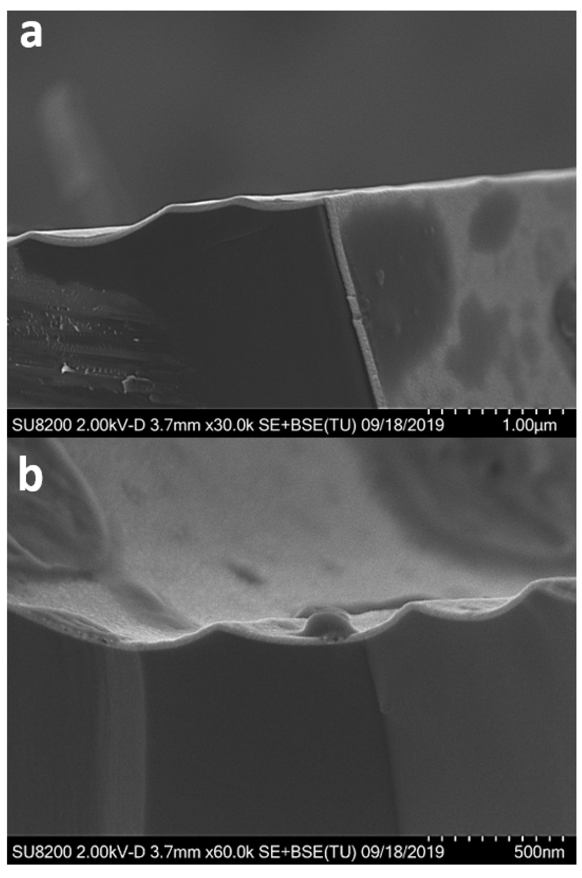
The ability to deposit catalytically active complex oxides on high aspect ratios is of high importance. This can, e.g., enable the coating of mesoporous γ-alumina, and thereby provide catalysts with a significantly enhanced surface area compared to nanoparticles (10–100 nm) obtained from wet chemical synthesis and/or ball milling. The conformality of the two gadolinium cobaltite-based films was investigated by applying the presented deposition process onto high-aspect-ratio substrates. Figure 5 shows cross section images of a GdCoO3 film deposited on a high-aspect-ratio trench Si wafer. The film is conformally deposited on all surfaces of the substrate. As shown in Figure 5b, the bottom of the trench is characterized by the presence of agglomerates, possibly resulting from turbulence during growth and/or the preparation of cross section SEM samples.
4. Conclusions
We have developed an ALD process for crystalline and homogeneous Gd‒Ca‒Co‒O thin films on three different substrates, which provides a route towards coatings with potential application within catalysis. The good crystallinity of the obtained films gives insight into the crystal structure of the product and orientation of crystallization, which is essential since catalytic performance depends on key parameters connected with the structure, chemistry, and electronic states of exposed surfaces. These features are shown to be tuned by appropriate choices of ALD precursors, substrates, and deposition/annealing conditions. The proof of concept of depositing conformal Gd‒Ca‒Co‒O films on high-aspect-ratio substrates is important, since practical applications in catalysis would require high surface areas.
The gadolinium cobaltite-based catalysts represent a particularly interesting system, not only with respect to catalysis, but also to physical properties. For instance, an expanded lattice triggered by the substrate may possibly stabilize a high-spin Co(III) state. Such scenarios suggest that ALD can be used to tune resulting properties by means of appropriate lattice-matching substrates.
Supplementary Materials
The following are available online at https://www.mdpi.com/1996-1944/13/1/24/s1: Figure S1: XRD patterns of 30 nm Gd0.9Ca0.1CoO3 films grown on (a) YAP(100) and (b) YAP(001), post-annealed for 30 minutes at 650 °C. Figure S2: XRD pattern of the GdCoO3 (040) reflection of as deposited (black) and annealed (green) 30 nm films grown on LAO (100)pc, used for Scherrer analysis of crystallite size. Figure S3: (a) XPS of C 1s, (b) XPS of O 1s and (c) Survey spectra showing identification of Gd, Co, O and carbon species.
Author Contributions
Investigation, M.D. and H.H.S.; formal analysis, M.D. and H.H.S.; methodology, H.H.S. and O.N.; project administration, O.N., A.O.S. and H.F.; writing—original draft preparation, M.D.; writing—review and editing, M.D., H.H.S., O.N., A.O.S. and H.F.; supervision, A.O.S. and H.F. All authors have read and agreed to the published version of the manuscript.
Funding
This project received financial support from the Research Council of Norway via the ASCAT project (contract no. 247753).
Acknowledgments
The authors acknowledge the Department of Geology at the University of Oslo for access to XRF instrumentation. Henrik H. Sønsteby acknowledges the Research Council of Norway for funding via the RIDSEM project (contract no. 272253). In addition, they thank Jon Einar Bratvold for his assistance with the ALD reactor, Kristian Weibye for recording XPS spectra, and Martin Jensen for recording SEM images.
Conflicts of Interest
The authors declare no conflict of interest.
References
- Royer, S.; Duprez, D.; Can, F.; Courtois, X.; Batiot-Dupeyrat, C.; Laassiri, S.; Alamdari, H. Perovskites as Substitutes of Noble Metals for Heterogeneous Catalysis: Dream or Reality. Chem. Rev. 2014, 114, 10292–10368. [Google Scholar] [CrossRef] [PubMed]
- Pena, M.A.; Fierro, J.L.G. Chemical Structures and Performance of Perovskite Oxides. Chem. Rev. 2011, 101, 1981–2018. [Google Scholar] [CrossRef] [PubMed]
- Kim, C.H.; Qi, G.; Dahlberg, K.; Li, W. Strontium-doped perovskites rival platinum catalysts for treating NOx in simulated diesel exhaust. Science 2010, 327, 1624–1627. [Google Scholar] [CrossRef] [PubMed]
- Fleming, P.; Farrell, R.A.; Holmes, J.D.; Morris, M.A. The Rapid Formation of La(OH)3 from La2O3 Powders on Exposureto Water Vapor. J. Am. Ceram. Soc. 2010, 93, 1187–1194. [Google Scholar] [CrossRef]
- Waller, D.; Grønvold, M.S.; Sahli, N. Ammonia Oxidation Catalyst for the Production of Nitric Acid Based on Yttrium-Gadolinium Ortho Cobaltates; World Intellectual Property Organization: New York, NY, USA, 2017. [Google Scholar]
- Duparc, M.; et al. 2019; Unpublished manuscript.
- Nagao, M.; Hamano, H.; Hirata, K. Hydration Process of Rare-Earth Sesquioxides Having Different Crystal Structures. Langmuir 2003, 19, 9201–9209. [Google Scholar] [CrossRef]
- Krishnamurthy, N.; Gupta, C.K. Extractive Metallurgy of Rare Earths; CRC Press: Boca Raton, FL, USA, 2004. [Google Scholar]
- Marichy, C.; Bechalany, M.; Pinna, N. Atomic Layer Deposition of Nanostructured Materials for Energy and Environmental Applications. Adv. Mater. 2012, 24, 1017–1032. [Google Scholar] [CrossRef]
- O’Neill, B. Catalyst Design with Atomic Layer Deposition. ACS Catal. 2015, 5, 1804–1825. [Google Scholar] [CrossRef] [Green Version]
- Camacho-Bunquin, J.; Shou, H.; Aich, P.; Beaulieu, D.R.; Klotzsch, H.; Bachman, S.; Marshall, C.L.; Hock, A.; Stair, P. Catalyst synthesis and evaluation using an integrated atomic layer deposition synthesis–catalysis testing tool. Rev. Sci. Instrum. 2015, 86, 84–103. [Google Scholar] [CrossRef] [Green Version]
- Suntola, T. Atomic layer epitaxy. Mater. Sci. Rep. 1989, 4, 261–312. [Google Scholar] [CrossRef]
- Leskelä, M.; Ritala, M. Atomic layer deposition (ALD): From precursors to thin film structures. Thin Solid Films 2002, 409, 138–146. [Google Scholar] [CrossRef]
- George, S.M. Atomic layer deposition: An overview. Chem. Rev. 2009, 110, 111–131. [Google Scholar] [CrossRef] [PubMed]
- Onn, T.M.; Dai, S.; Chen, J.; Pan, X.; Graham, G.W.; Gorte, R.J. High-Surface Area Ceria-Zirconia Films Prepared by Atomic Layer Deposition. Catal. Lett. 2017, 147, 1464–1470. [Google Scholar] [CrossRef]
- Onn, T.M.; Monai, M.; Dai, S.; Arroyo-Ramirez, L.; Zhang, S.; Pan, X.; Graham, G.W.; Fornasiero, P.; Gorte, R.J. High-surface-area, iron-oxide films prepared by atomic layer deposition on γ-Al2O3. Appl. Catal. A Gen. 2017, 534, 70–77. [Google Scholar] [CrossRef] [Green Version]
- Miikkulainen, V.; Leskelä, M.; Ritala, M.; Puurunen, R.L. Crystallinity of inorganic films grown by atomic layer deposition: Overview and general trends. J. Appl. Phys. 2013, 113, 2. [Google Scholar] [CrossRef]
- Sønsteby, H.H.; Fjellvåg, H.; Nilsen, O. Functional Perovskites by Atomic Layer Deposition—An Overview. Adv. Mater. Interfaces 2017, 4, 1600903. [Google Scholar] [CrossRef]
- Johnson, R.W.; Hultqvist, A.; Bent, S.F. A brief review of atomic layer deposition: From fundamentals to applications. Mater. Today 2014, 17, 236–246. [Google Scholar] [CrossRef]
- Ahvenniemi, E.; Matvejeff, M.; Karppinen, M. Atomic layer deposition of quaternary oxide (La,Sr)CoO3−δ thin films. Dalton Trans. 2015, 44, 8001–8006. [Google Scholar] [CrossRef]
- Seim, H.; Nieminen, M.; Niinistö, L.; Fjellvåg, H.; Johansson, L.S. Growth of LaCoO3 thin films from β-diketonate precursors. Appl. Surf. Sci. 1997, 112, 243–250. [Google Scholar] [CrossRef]
- Sønsteby, H.H.; Bratvold, J.E.; Weibye, K.; Fjellvåg, H.; Nilsen, O. Phase Control in Thin Films of Layered Cuprates. Chem. Mater. 2018, 30, 1095–1101. [Google Scholar] [CrossRef]
- Klepper, K.B.; Nilsen, O.; Fjellvåg, H. Growth of thin films of Co3O4 by atomic layer deposition. Thin Solid Fims 2007, 515, 7772–7781. [Google Scholar] [CrossRef]
- Niinistö, J.; Petrova, N.; Putkonen, M.; Niinistö, L.; Arstila, K.; Sajavaara, T. Gadolinium oxide thin films by atomic layer deposition. J. Cryst. Growth 2005, 285, 191–200. [Google Scholar] [CrossRef]
- Sønsteby, H.H.; Østreng, E.; Fjellvåg, H.; Nilsen, O. Deposition and x-ray characterization of epitaxial thin films of LaAlO3. Thin Solid Films 2014, 550, 90–94. [Google Scholar] [CrossRef]
- Leskelä, M.; Ritala, M.; Nilsen, O. Novel materials by atomic layer deposition and molecular layer deposition. MRS Bull. 2011, 36, 877–884. [Google Scholar] [CrossRef]
- Bretos, I.; Ricote, J.; Jiménez, R.; Mendiola, J.; Jiménez Riobóo, R.J.; Calzada, M.L. Crystallisation of Pb1−xCaxTiO3 ferroelectric thin films as a function of the Ca2+ content. J. Eur. Ceram. Soc. 2005, 25, 2325–2329. [Google Scholar] [CrossRef]
- Orlov, Y.S.; Solovyov, L.A.; Dudnikov, V.A.; Fedorov, A.S.; Kuzubov, A.A.; Kazak, N.V.; Voronov, V.N.; Vereshchagin, S.N.; Shishkina, N.N.; Perov, N.S.; et al. Structural properties and high-temperature spin and electronic transitions in GdCoO3: Experiment and theory. Phys. Rev. B 2013, 81, 235105. [Google Scholar] [CrossRef]
Figure 1.
Deposited cation ratio (cat.% Gd, as measured by XRF) and GPC as a function of the pulsed cation ratio (cat.% Gd) for (Gd, Co)-oxide films deposited at 300 °C. The dotted lines refer to deposited cation ratio (cat.% Gd) and GPC as a function of the pulsed cation ratio (cat.% Gd) for Gd2O3 film.
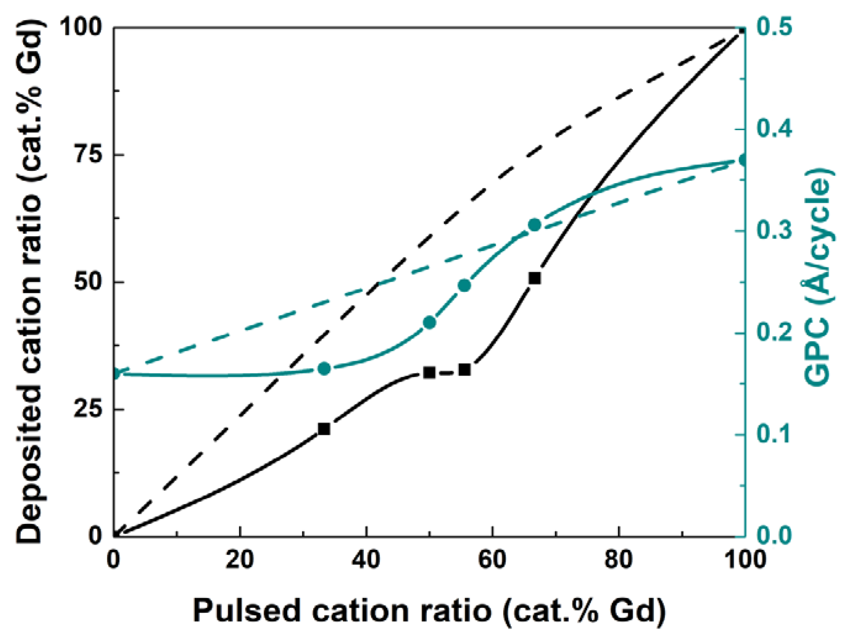
Figure 2.
(a) Deposited cation ratio (cat.% Ca, as measured by XRF) and (b) GPC deposited cation ratio (cat. % (Gd + Ca) and Co, as measured by XRF) as a function of the pulsed cation ratio (cat.% Ca) for (Gd, Ca, Co) films deposited at 300 °C. The dotted line indicates the targeted Ca deposited concentration.
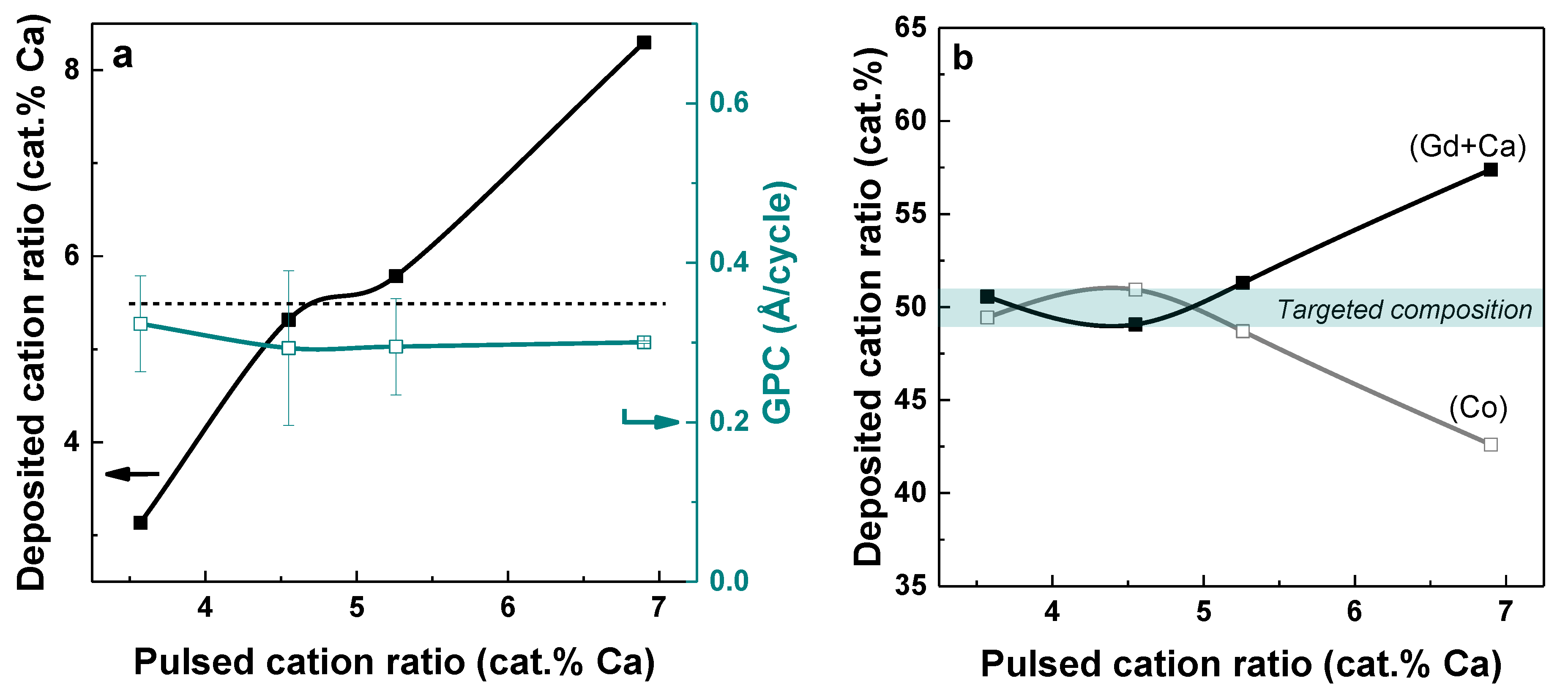
Figure 3.
XRD patterns of (a) 30 nm GdCoO3 and (b) 30 nm Gd0.9Ca0.1CoO3 films grown on LAO(100), (c) 30 nm GdCoO3 grown on YAP(100) and (d) 30 nm GdCoO3 grown on YAP(001), post-annealed for 30 min at 650 °C. Bragg reflections originating from the substrate are marked with a star; film reflections are marked with their designated plane of reflection.

Figure 4.
Co 2p XPS of 30 nm GdCoO3 thin films on LaAlO3 (100), with no observation of Co2+. The black line is the recorded data, the green line is the background, and the light blue line is the total fit.
Figure 4.
Co 2p XPS of 30 nm GdCoO3 thin films on LaAlO3 (100), with no observation of Co2+. The black line is the recorded data, the green line is the background, and the light blue line is the total fit.
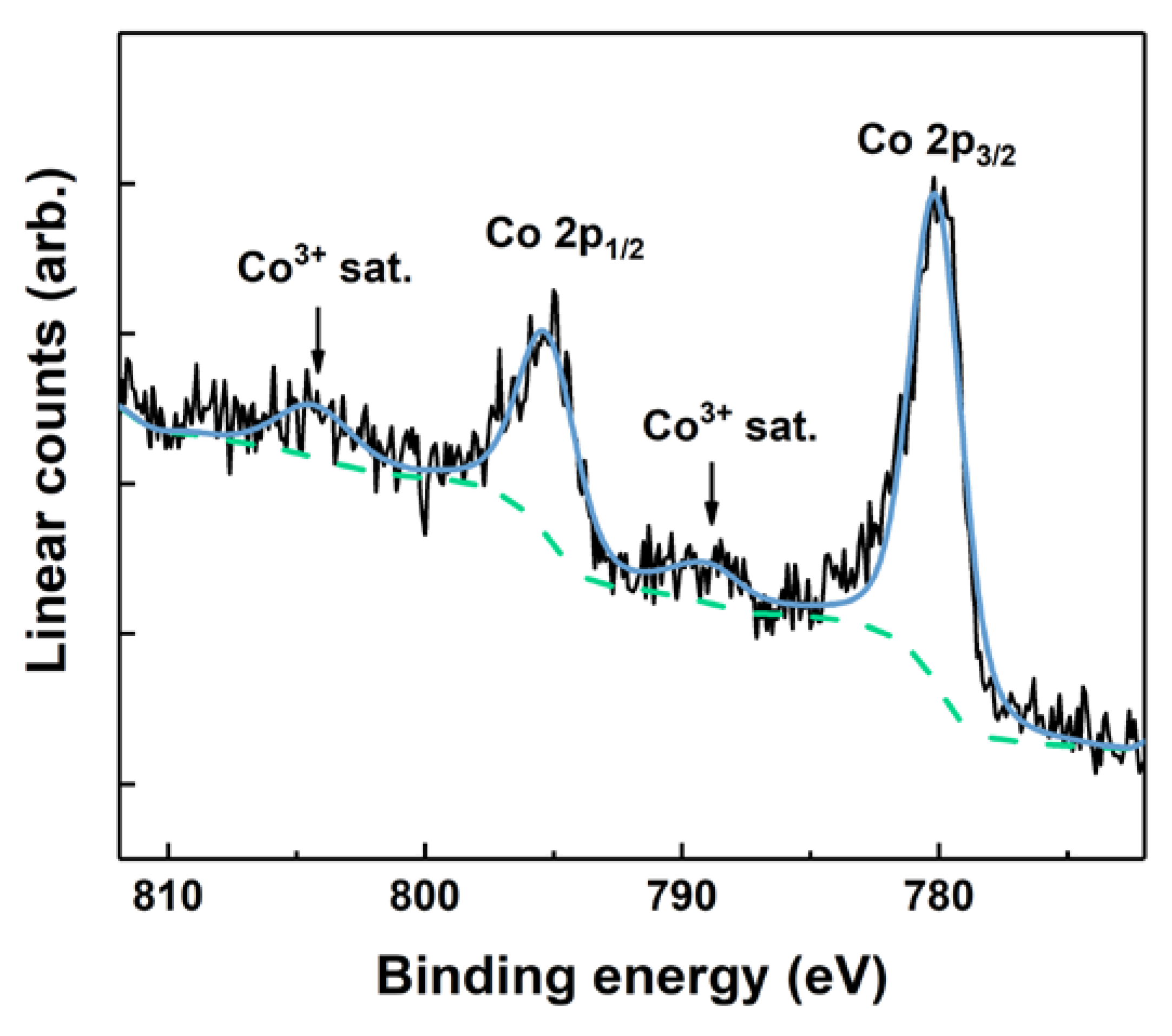
Figure 5.
SEM cross-sectional images of GdCoO3 deposited on a trench Si wafer: (a) top trench view; (b) bottom trench view.
Figure 5.
SEM cross-sectional images of GdCoO3 deposited on a trench Si wafer: (a) top trench view; (b) bottom trench view.
© 2019 by the authors. Licensee MDPI, Basel, Switzerland. This article is an open access article distributed under the terms and conditions of the Creative Commons Attribution (CC BY) license (http://creativecommons.org/licenses/by/4.0/).
Share and Cite
MDPI and ACS Style
Duparc, M.; Sønsteby, H.H.; Nilsen, O.; Sjåstad, A.O.; Fjellvåg, H. Atomic Layer Deposition of GdCoO3 and Gd0.9Ca0.1CoO3. Materials 2020, 13, 24. https://doi.org/10.3390/ma13010024
AMA Style
Duparc M, Sønsteby HH, Nilsen O, Sjåstad AO, Fjellvåg H. Atomic Layer Deposition of GdCoO3 and Gd0.9Ca0.1CoO3. Materials. 2020; 13(1):24. https://doi.org/10.3390/ma13010024
Chicago/Turabian StyleDuparc, Marion, Henrik Hovde Sønsteby, Ola Nilsen, Anja Olafsen Sjåstad, and Helmer Fjellvåg. 2020. "Atomic Layer Deposition of GdCoO3 and Gd0.9Ca0.1CoO3" Materials 13, no. 1: 24. https://doi.org/10.3390/ma13010024
Note that from the first issue of 2016, this journal uses article numbers instead of page numbers. See further details here.