Research on Anisotropic Viscoelastic Constitutive Model of Compression Molding for CFRP


1
School of Mechanical Engineering, Tianjin University, Tianjin 300350, China
2
School of Mechanical Engineering, Tianjin Sino-Germen University of Applied Sciences, Tianjin 300350, China
3
Tianjin Sinotech Industry Co., Ltd., Tianjin 300350, China
*
Authors to whom correspondence should be addressed.
Materials 2020, 13(10), 2277; https://doi.org/10.3390/ma13102277
Submission received: 10 April 2020
/
Revised: 11 May 2020
/
Accepted: 12 May 2020
/
Published: 15 May 2020
(This article belongs to the Special Issue Carbon Fiber Reinforced Polymers)
Abstract
:The carbon-fiber-reinforced polymer (CFRP) is a mainstream material for lightweight products from the end of the 20th century to the present day. Its compression molding process has obvious advantages in mass production. This paper attempts to establish the constitutive models of compression molding of the CFRP materials and study their mechanism. Based on anisotropic linear elastic mechanics, viscoelastic mechanics, and thermodynamics, as well as the Maxwell viscoelastic constitutive model, we first establish the constitutive model of thermorheologically simple CFRP materials (TSMs). Then, considering the influence of temperature on the initial stiffness and equilibrium stiffness, the concept of temperature stiffness coefficient is introduced, and the Cartier coordinate system is converted into a cylindrical coordinate system, thereby establishing the constitutive model of thermorheologically complex materials (TCMs) using the tensor form. Finally, by comparing to the structure of the Zocher model, the two constitutive models established in this study are verified. The research findings have important theoretical research significance for studying the compression molding mechanism of carbon fiber and further improving the quality of product molding.
1. Introduction
Carbon fiber is one of the most relevant materials from the end of the 20th century to the present day. Due to its characteristics such as high specific strength, high specific modulus, fatigue resistance, good molding process, good breakage safety, and strong performance designability, the carbon-fiber-reinforced polymer (CFRP) has been increasingly applied in aerospace, wind turbine blades, sports equipment, and automotive parts, etc. It is the mainstream material for lightweight products in the 21st century [1,2,3], gradually transiting from secondary load-bearing components to primary load-bearing components.
Commonly used molding methods of the CFRP materials include compression molding, autoclave, winding, and the squeezing method, etc. Among them, the compression molding method has the advantages of low cost, high efficiency, low internal stress, small warpage, good mechanical stability, and high repeatability, and it has a strong competitive advantage in the batch production of product parts, especially in large batch production [4,5]. However, the compression molding process is disturbed by multiple physical fields, multiple process parameters, the characteristics of the material itself, the thermochemical reaction of the substrate, etc., resulting in residual stress during the molding process of the product, which directly affects the curing deformation of the material [6,7]. Therefore, the constitutive model of the CFRP molding process should be established. It is of great significance for reasonably predicting the residual stress development of the product molding process, optimizing the molding process, and improving product quality.
Scholars worldwide have conducted a lot of research based on the constitutive model of the CFRP materials and achieved rich results. The linear elastic constitutive equation combined with laminate theory is a commonly used method to predict the residual stress of composite materials. Stango et al. [8] assumed that the material properties during the curing process were constants and adopted the laminate theory to study the temperature-induced composite residual stress. Bogetti et al. [9] believed that the performance of the composite material was related to the curing degree and proposed an improved linear elastic constitutive model, namely the CHILE () model. Johnston [10] stated that the performance of the composite material during curing is related to the glass transition temperature Tg of the matrix, and they established the CHILE () model. In essence, both the CHILE () and CHILE () models are linear elastic constitutive models, which cannot reflect the characteristics of material stress relaxation and creep; the CFRP resin matrix exhibits obvious viscoelastic properties at high temperatures. Thus, the viscoelastic constitutive model can truly describe the mechanical properties of composite materials during curing. Zocher et al. [11] used the generalized Maxwell model and Prony technology to express the relaxation stiffness of composite materials, and they derived the anisotropic constitutive equation and incremental equation. Kim et al. [12,13] assumed that Poisson’s ratio of the resin during the curing process was unchanged, and combined the time–temperature-curing degree equivalence principle to obtain the viscoelastic properties of related resins, which provided important references for understanding the viscoelastic behavior of the materials during curing. Zobeiry et al. [14] used a differential type to represent the viscoelastic constitutive equation and its increment. Abouhamzeh et al. [15] combined the Laplace transform and inverse transform and proposed a solution to predicting the viscoelastic behavior of anisotropic composite materials. Svanberg et al. [16] proposed a path-dependent constitutive model and studied the curing and post-curing deformation mechanism of L-shaped parts.
Based on the previous research, this paper establishes the CFRP anisotropic viscoelastic constitutive models of thermorheologically simple CFRP materials (TSMs) and thermorheologically complex materials (TCMs) by combining with anisotropic linear elastic mechanics, viscoelastic theory, and thermodynamics, and the Maxwell viscoelastic model. Considering the effect of material temperature on the stiffness and equilibrium stiffness of the carbon fiber molding process, the temperature-dependent thermoelastic stiffness coefficient was introduced, and the Cartesian coordinate system was converted into a cylindrical coordinate system, thereby establishing the CFRP anisotropic elastic constitutive equation and increment equations of the TCM materials. The establishment of the CFRP anisotropic viscoelastic constitutive models, especially for TCM materials, will lay a theoretical foundation for revealing the mechanism of carbon-fiber-reinforced polymers [17], and then provide theoretical guidance to improve the quality of products molding, to further speed up the industrialization process of CFRP.
2. Theoretical Basis of CFRP Compression Molding
Generally, if the performance of each point in the object is the same, it is a homogeneous material, otherwise, a heterogeneous material. In addition, materials that show the same properties in every direction at every point in the object are called isotropic materials, while those with different properties at every point in the object are anisotropic materials. For a CFRP material, the matrix is an isotropic material, and the reinforcing fiber is a transversely isotropic body, so the CFRP material is an anisotropic material. In the molding process of CFRP materials, the matrix material has undergone a transition process from the viscous fluid state to rubber state to glass state, etc. It is necessary to combine the elastic mechanics of the composite material and the viscoelastic mechanics in the research.
2.1. The basis of Anisotropic Linear Elastic Mechanics
To study the mechanical properties of composite materials and solve the stress and strain of a continuous elastomer under external load, we need to balance the equations, geometric equations, constitutive equations, etc.
In the space coordinate system , the stress state of any point in the elastic body under any load is represented by the normal stress components , , and , and the shear stress components , , and . According to the theorem of conjugate shearing stress, there is , , and . , , and respectively represent the external force components received by the elastic body in the , , and directions. Ignoring the volume force, the equilibrium relationship of any point in the elastic body along the coordinate axes , , and is:
Similarly, in the space coordinate system , the strain state of any point on the elastic body can be represented by the normal strain components , , and and the shear strain components , , and at that point. If , , and represent the displacement components in the three directions of x, y, and z, then the geometric equation of any point in the elastic body along the , , and directions is:
According to Equations (1) and (2), in the space coordinate system , there are 15 unknown functions, namely 6 stress components, 6 strain components, and 3 displacement components. Their relationship is shown as:
Among them, ( = 1, 2, 3, 4, 5, 6) is the stiffness coefficient.
The matrix of the stiffness coefficient is symmetric, and only 21 stiffness coefficients are independent. Equation (3) establishes the relationship between stress and strain, which is called the generalized Hooke’s law or elastic constitutive equation.
For the matrix of a CFRP material, the number of independent stiffness coefficients is 2, and its stress–strain relationship is
The reinforced fiber has 5 independent stiffness coefficients. Assuming that the coordinate plane is isotropic, its stress–strain relationship is
2.2. The Basis of Anisotropic Viscoelastic Mechanics
The mechanical properties of viscoelastic materials such as shear modulus, loss modulus, and loss factor, etc. are usually related to ambient temperature, vibration frequency, strain amplitude, etc. Therefore, the constitutive relationship of viscoelastic materials is very complicated.
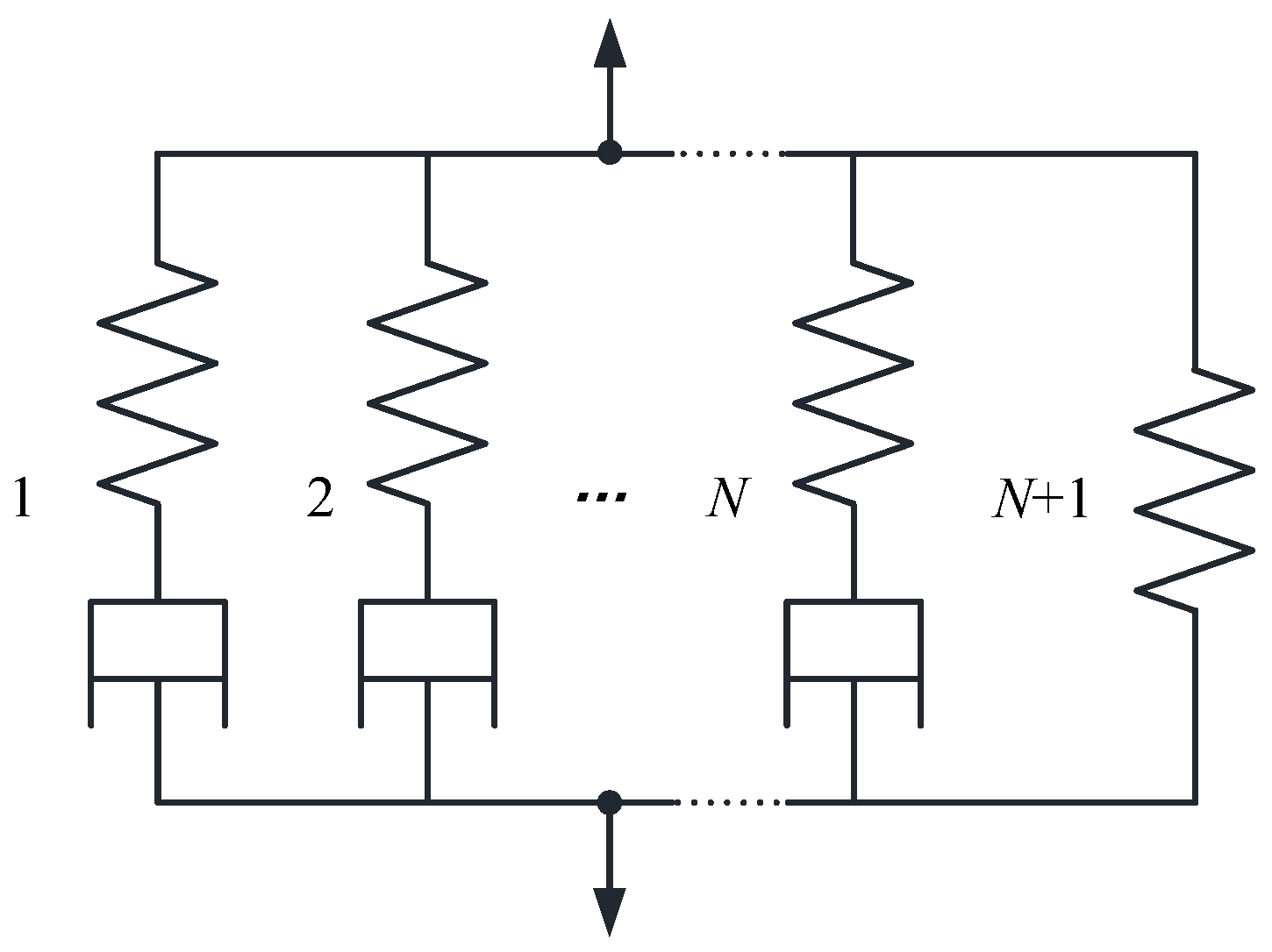
When describing the viscoelastic behavior of materials, the generalized Maxwell model is generally used, which consists of multiple Maxwell elements in parallel with a spring, as shown in Figure 1:
Each Maxwell element contains a spring with elastic modulus E and a viscous strain damper with strain viscosity . In the generalized Maxwell model, the modulus is used to measure the performance of the spring, and the relaxation time is used to express the performance of the damper. The constitutive equation of anisotropic viscoelastic materials [18,19,20,21] is:
where is the stiffness matrix, is the effective strain tensor, and , , and are the stress tensor, curing degree, and virtual time integral variable of the tensor, respectively.
The effective strain tensor can be expressed by the total strain tensor and the non-mechanical strain tensor , namely:
If the material exhibits simple thermo-rheological properties when cured, the above equation can be changed to:
where is the time and is expressed as:
Among them, is the conversion equation, related to temperature and curing degree; is the time integral variable.
The stiffness matrix is represented by the Prony series:
where is the stiffness matrix after the material is completely relaxed, that is, the equilibrium stiffness; is the stiffness matrix of each m branch in the Prony series; is the discrete relaxation time of the m-th branch.
2.3. The Basis of Thermodynamics
During the molding process of the composite material, the matrix undergoes a curing reaction to release heat, which is regarded as an internal heat source and controls the entire heat transfer process together with the applied temperature.
According to the Fourier heat conduction equation, the heat transfer process can be expressed as:
where , , , , and respectively represent the density, specific heat, and anisotropic thermal conductivity of the composite material; is the temperature at time ; is the heat generated by the curing reaction of the resin, which can be calculated as
In Equation (13), is the resin matrix density, is the fiber volume fraction, is the total heat released by the resin during complete curing, and is the instant curing rate of the resin. The curing degree can be expressed as
The boundary conditions of the heat conduction model are:
where and are the surface temperature and heating temperature of the composite material, respectively; and are the equivalent thermal conductivity and equivalent convection heat transfer coefficients of the composite material surface, respectively.
3. CFRP Constitutive Model of the TSMs
The viscoelastic constitutive modulus can reflect the creep and relaxation characteristics of the material. In this paper, the generalized Maxwell viscoelastic constitutive equation was used to reflect the viscoelastic characteristics of the simple thermal-rheological composite material.
3.1. The Constitutive Model Based on Viscoelastic Theory
For a single Maxwell element, the strain of the element is a combination of spring and viscous element strain, which is expressed as
Using the relaxation modulus to express the relaxation characteristics of the material,
where , i.e., the relaxation time.
For the generalized Maxwell model, the stress relaxation modulus is given as
and are the elastic modulus and relaxation time of the m-th branch, respectively.
It can be seen from Figure 1 that the N + 1-th unit has only one spring, the relaxation modulus of the viscous element is negligible, and its elastic modulus is the modulus after complete relaxation. The initial modulus of the generalized Maxwell model is , and it can then be expressed as
where is the weight coefficient, which is expressed as
The stress of the m-th branch in the generalized Maxwell model at time t is expressed as
Its difference form is
where and , , and represent the stress tensor and effective strain tensor before and after the time increment , respectively, and , respectively represent the relaxation time and stiffness matrix of the m-th branch of the Maxwell model at time t. The effective stress tensor can be expressed as
Among them, represents the total stress tensor, and represent the effective thermal expansion coefficient and chemical shrinkage coefficient, respectively, is the temperature increment, and is the curing degree increment.
Combining the stresses of all branches of the Maxwell model and the balance spring, we obtain the total stress at time t:
Based on the above, the stress increment at time t can be expressed as
where represents the stiffness matrix of the spring, and the stiffness matrix of the m-th branch can be expressed as
is the initial stiffness matrix and is the stiffness matrix after complete relaxation. Generally, ; r is a constant, and different material systems have different values of r.
The conversion equation can be expressed as
Among them, and are constants, and different matrices have different values.
3.2. CFRP Viscoelastic Constitutive Equation and Incremental Equation of the TSMs
When the CFRP materials are TSMs, the material’s equilibrium stiffness and initial stiffness are unrelated with the degree of curing. According to Equations (11), (19), and (27), the relaxation stiffness of the CFRPs can be expressed as:
Considering the effects of temperature T and curing degree on relaxation stiffness, the above equation can be expressed as:F
Considering the stress increment within the time increment , there is
When the time increment is small, the curing degree is considered to be approximately constant, that is,
Therefore, the stress increment can be expressed as: [24]
where is a historical state variable; the initial value is 0, which can be expressed as:
4. CFRP Constitutive Model of the TCMs
4.1. Thermoelastic Expressions of the TCMs
To simulate the high-temperature viscoelastic behavior of composite materials, it is generally assumed that the composite material is a simple thermal-rheological material, that is, the equilibrium stiffness and initial stiffness of the material are related to temperature and curing degree. Many experiments have shown that the initial stiffness and equilibrium stiffness are related to the material temperature [25]. In this paper, the viscoelastic materials whose equilibrium stiffness and initial stiffness change with temperature are called thermorheologically complex materials.
In the curing process of composite materials, the molding temperature and the curing degree of the matrix change with time, and the elastic modulus of the material is related to the temperature and the curing degree. On the one hand, it affects the conversion factor and relaxation time, similar to the performance of the viscous elements; on the other hand, it also affects and , which is similar to the elastic properties.
When constructing the viscoelastic model of the material in this paper, the vertical movement coefficient representing the correlation between and temperature was added to be the thermal viscosity stiffness coefficient. Through the experimental method and data processing method provided by Kim [12,13], the exponential function was used to express the thermoelastic stiffness coefficient of an epoxy resin base, and linearly fit it, as shown in Figure 2 below.
4.2. Conversion of Coordinate Systems
For a better description in the study of the CFRP mechanical properties, it is necessary to establish a local coordinate system for the geometric elements or convert the global coordinate system. In this paper, the Cartesian coordinate axis was converted into a cylindrical coordinate system for reducing the amount of calculation.
In the Cartesian coordinate system (,,), the unit base vectors of the coordinate axes are , , and , respectively, and the unit vectors converted into the cylindrical coordinate system are , , and , respectively. It is shown as
Then, the conversion formula in the Cartesian coordinate system and cylindrical coordinate system is:
The stress vector in the cylindrical coordinate system can be expressed by the stress vector in the Cartesian coordinate system, namely:
where .
4.3. CFRP Viscoelastic Constitutive Equation and Enhancement Equation of the TCMs
As the anisotropic viscoelastic constitutive model of TCMs contains many factors, the tensor was used in this paper to express the three-dimensional viscoelastic constitutive model and incremental equations of TCMs.
For the one-dimensional Maxwell element, the stress relaxation under unit constant strain is equal to the relaxation modulus of the model. In view of the thermoelastic stiffness coefficient, the relaxation modulus of the element at time t is:
where d is the thermoelastic stiffness coefficient, .
is the spring stiffness and is the spring stiffness at t = 0.
For the three-dimensional generalized Maxwell model, the Cartier coordinate system was converted into a cylindrical coordinate system to express the relaxation modulus. At this time, it appeared to be isotropic on the xoy plane. When calculating, the three-dimensional generalized model is equivalent to the two-dimensional generalized model, which can be compared to the relaxation modulus representation of a one-dimensional Maxwell element,
Then, the thermoelastic stiffness coefficient is .
According to Equation (32), the stress value at time t is:
According to Equations (44) and (45), the stress at the reduced time can be rewritten as:
The relaxation modulus is expressed as:
Referring to (46), the stress at the reduced time is expressed as:
In the formula, the reduced time is discretized for the sum of the reduced time at time t and the reduced time increment at time , that is:
Thus,
The stress increment equation at time t is expressed as:
Among them, can be written in recursive form,
At very small time increments, the temperature T and the curing degree are extremely small and negligible, and the conversion factor is constant, so it can be expressed as:
In addition,
Then,
Use the same method to deal with and .
Finally, the stress increment at time t is expressed as:
In addition,
5. Verification of the Constitutive Models
To verify the constitutive models of both TSM and TCM CFRP materials, this paper selects the molded flat structure of a CFRP material based on Kim’s research [12,13]. Four layers were molded in the layering angle of [0/90/90/0]. Compared to the viscoelastic constitutive model proposed by Zocher [11], the curing degree change of the center point (0, 0, 0) of the laminate during the curing process is shown in Figure 3 below:
It can be seen from Figure 3 that the three curves are basically coincident, verifying the constitutive models given in this paper.
6. Conclusions
This paper studies the constitutive models of the CFRP during the compression molding process. The main content and conclusions are as follows:
- On the basis of the constitutive model of CFRP molding and viscoelastic theory, viscoelastic mechanics, and thermodynamics, the CFRP viscoelastic constitutive equation and incremental equation of the TSMs were established, which lays a foundation for explaining the solidification and relaxation behavior of the molding process.
- Considering the effects of temperature on the initial stiffness and equilibrium stiffness, the thermoelastic stiffness coefficient was introduced, and the Cartesian coordinate system was converted to the cylindrical coordinate system. Thus, the viscoelastic constitutive equation and incremental equation of the TCMs were established, and the accuracy and application range of the constitutive model were improved while the calculation scale was reduced.
- On the basis of the viscoelastic constitutive model proposed by Zocher, the correctness and validity of the constitutive models for TSMs and TCMs were verified by comparing the change in curing degree under the anisotropic viscoelastic constitutive model.
Author Contributions
Methodology and formal analysis, J.X.; methodology, S.W.; data curation, Z.C.; writing—original draft preparation, J.W.; writing—original draft preparation, X.Z. All authors have read and agreed to the published version of the manuscript.
Funding
The authors are grateful to Tianjin Research and Development Project 19JCTPJC41700, 19JCTPJC43100, 19YFZCGX00780, and Jinnan Project 2019ZD21.
Acknowledgments
The research of this paper is made possible by the generous support from Tianjin Sino-German University of Applied Sciences and Tianjin University.
Conflicts of Interest
The authors declare no conflict of interest.
References
- Du, S.Y. Advanced Composite Materials and Aerospace Engineering. Acta Mater. Compos. Sin. 2007, 24, 12. [Google Scholar]
- Ding, A.X.; Li, S.X.; Ni, A.Q.; Wang, J.H. A Review of Numerical Simulation of Cure-Induced Distortions and Residual Stresses in Thermoset Composites. Acta Mater. Compos. Sin. 2017, 34, 471–485. [Google Scholar]
- Molchanov, E.S.; Yudin, V.E.; Kydralieva, K.A.; Elokhovskii, V.Y. Comparison of the thermomechanical characteristics of porcher carbon fabric-based composites for orthopaedic applications. Mech. Compos. Mater. 2012, 48, 343–350. [Google Scholar] [CrossRef]
- Wang, Q.; Lv, J.H.; Liu, Z. A Lightweight Design of Carbon Fiber Reinforced Plastic Auto Bumper. J. Shanghai Jiao Tong Univ. 2017, 51, 136–141. [Google Scholar]
- Zhang, X.; Liu, Y.; Yang, B. Effect of Carbon Fiber Surface Modification on Properties of Composites. J. Funct. Polym. 2017, 30, 444–449. [Google Scholar]
- Maligno, A.R.; Warrior, N.A.; Long, A.C. Effects of interphase material properties in unidirectional fiber reinforced composites. Compos. Sci. Technol. 2010, 70, 36–44. [Google Scholar] [CrossRef]
- Corbridge, D.M.; Harper, L.T.; De Focatiis, D.S.A.; Warrior, N.A. Compression moulding of composites with hybrid fiber architectures. Compos. Part A Appl. Sci. Manuf. 2017, 95, 87–99. [Google Scholar] [CrossRef]
- Stango, R.J.; Wang, S.S. Process-induced residual thermal stresses in advanced fiber-reinforced composite laminates. J. Manuf. Sci. Eng. 1984, 106, 48–54. [Google Scholar] [CrossRef]
- Bogetti, T.A.; Gillespie, J.W. Process-induced stress and deformation in thick-section thermoset composite laminates. J. Compos. Mater. 1992, 26, 626–660. [Google Scholar] [CrossRef]
- Johnston, A.; Vaziri, R.; Poursartip, A. A plane strain model for process-induced deformation of laminated composite. J. Compos. Mater. 2001, 35, 1435–1469. [Google Scholar] [CrossRef]
- Zocher, M.A.; Groves, S.E.; Allen, D.H. A three-dimensional finite element formulation for thermoviscoelastic orthotropic media. Int. J. Numer. Methods Eng. 1997, 40, 2267–2288. [Google Scholar] [CrossRef]
- Kim, Y.K.; White, S.R. Cure-dependent viscoelastic residual stress analysis of filament- wound composite cylinders. Mech. Mater. Struct. 1999, 5, 327–354. [Google Scholar] [CrossRef]
- Kim, Y.K.; White, S.R. Stress relaxation behavior of 3501-6 epoxy resin during cure. Polym. Eng. Sci. 1996, 36, 2852–2862. [Google Scholar] [CrossRef]
- Zobeiry, N.; Vaziri, R.; Poursartip, A. Computationally efficient pseudo-viscoelastic models for evaluation of residual stresses in thermoset polymer composites during cure. Compos. Part A Appl. Sci. Manuf. 2010, 41, 247–256. [Google Scholar] [CrossRef]
- Abouhamzeh, I.M.; Sinke, J.; Jansen, K.M.B.; Benedictus, R. Thermo-viscoelastic Analysis of GLARE. Compos. Part B Eng. 2016, 99, 1–8. [Google Scholar] [CrossRef]
- Svanberg, J.M.; Holmberg, J.A. Prediction of shape distortions. Part II. Experimental validation and analysis of boundary conditions. Compos. Part A (Appl. Sci. Manuf.) 2004, 35, 723–734. [Google Scholar] [CrossRef]
- Wang, Y.; Huang, Z.M. Analytical Micromechanics Models for Elastoplastic Behavior of Long Fibrous Composites: A Critical Review and Comparative Study. Materials 2018, 11, 1919. [Google Scholar] [CrossRef] [Green Version]
- White, S.R.; Kim, Y.K. Process-Induced residual stress analysis AS4/3501-6 Composite material. Mech. Compos. Mater. Struct. 1998, 5, 153–186. [Google Scholar] [CrossRef]
- Kim, Y.K. Process-Induced Residual Stress Analysis by Resin Transfer Molding. J. Compos. Mater. 2004, 38, 959–972. [Google Scholar] [CrossRef]
- Christensen, R. Theory of Viscoelasticity: An Introduction; Elsevier: Amsterdam, The Netherlands, 1982. [Google Scholar]
- Lee, S.Y.; Kang, J.K. Residual Stresses in a Laminated Shell during Cure. KSME Int. J. 1999, 13, 625–633. [Google Scholar] [CrossRef]
- Zhu, Q.; Geubelle, P.H. Dimensional Accuracy of Thermoset Composites: Shape Optimization. J. Compos. Mater. 2002, 36, 647–672. [Google Scholar] [CrossRef]
- Kim, B.-S.; Bernet, N.; Sunderland, P.; Manson, J.-A. Numerical Analysis of the Dimensional Stability of Thermoplastic Composites Using a Thermoviscoelastic Approach. J. Compos. Mater. 2002, 36, 2389–2403. [Google Scholar] [CrossRef]
- Ding, A.; Li, S.; Wang, J.; Zu, L. A three-dimensional thermo-viscoelastic analysis of process-induced residual stress in composite laminates. Compos. Struct. 2015, 129, 60–69. [Google Scholar] [CrossRef]
- Liu, C.; Shi, Y. An Improved Analytical Solution for Process-Induced Residual Stresses and Deformations in Flat Composite Laminates Considering Thermo-Viscoelastic Effects. Materials 2018, 11, 2506. [Google Scholar] [CrossRef] [Green Version]
Figure 1.
Generalized Maxwell model.

Figure 2.
The thermoelastic stiffness coefficient of an epoxy resin.

Figure 3.
Comparison of the changes of (0,0,0) curing degree.

© 2020 by the authors. Licensee MDPI, Basel, Switzerland. This article is an open access article distributed under the terms and conditions of the Creative Commons Attribution (CC BY) license (http://creativecommons.org/licenses/by/4.0/).
Share and Cite
MDPI and ACS Style
Xie, J.; Wang, S.; Cui, Z.; Wu, J.; Zhou, X. Research on Anisotropic Viscoelastic Constitutive Model of Compression Molding for CFRP. Materials 2020, 13, 2277. https://doi.org/10.3390/ma13102277
AMA Style
Xie J, Wang S, Cui Z, Wu J, Zhou X. Research on Anisotropic Viscoelastic Constitutive Model of Compression Molding for CFRP. Materials. 2020; 13(10):2277. https://doi.org/10.3390/ma13102277
Chicago/Turabian StyleXie, Jiuming, Shiyu Wang, Zhongbao Cui, Jin Wu, and Xuejun Zhou. 2020. "Research on Anisotropic Viscoelastic Constitutive Model of Compression Molding for CFRP" Materials 13, no. 10: 2277. https://doi.org/10.3390/ma13102277
Note that from the first issue of 2016, this journal uses article numbers instead of page numbers. See further details here.