The Examination of Restrained Joints Created in the Process of Multi-Material FFF Additive Manufacturing Technology

 ,
,  ,
,  ,
,  ,
,  and
and
Abstract
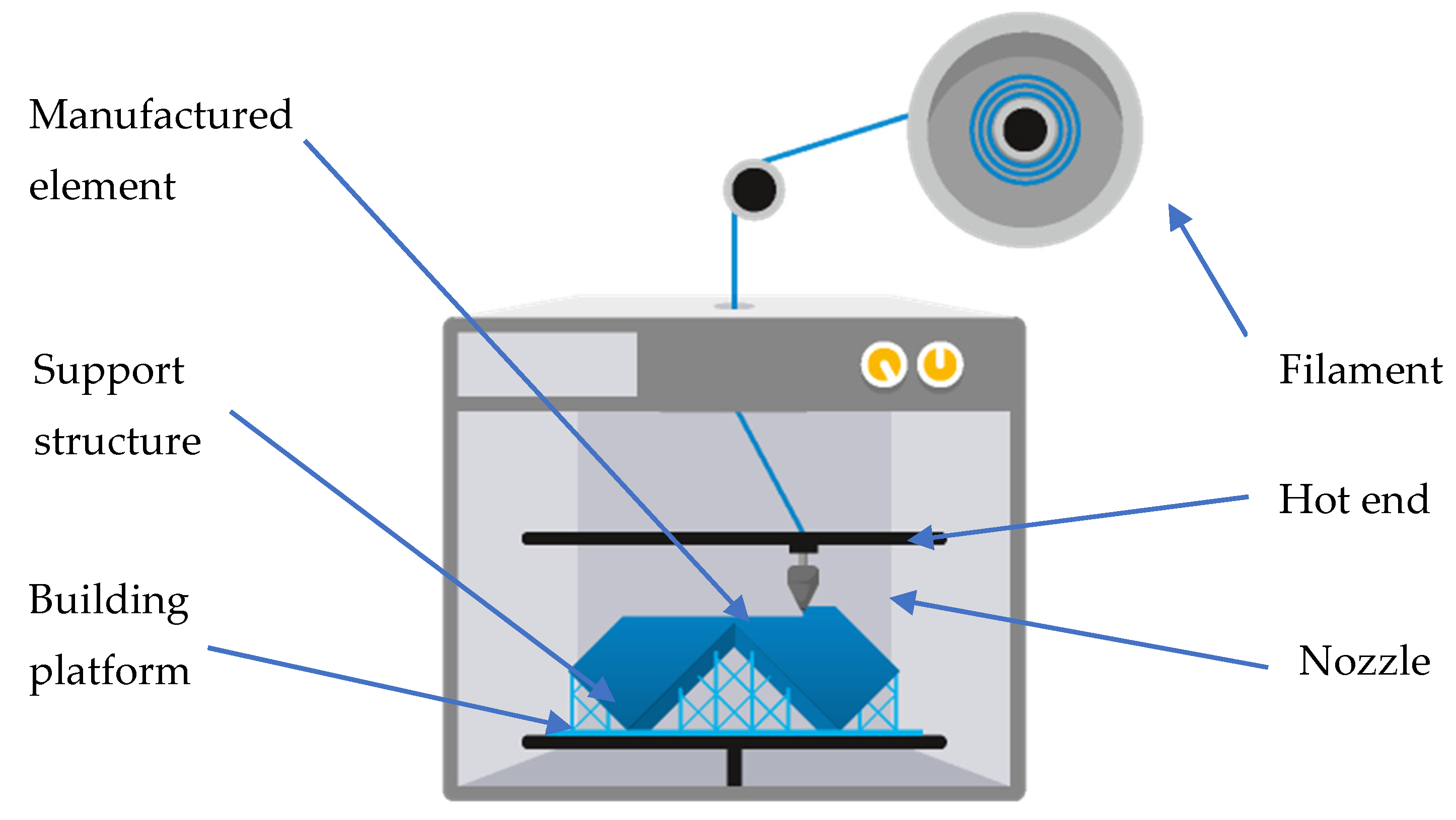
:1. Introduction
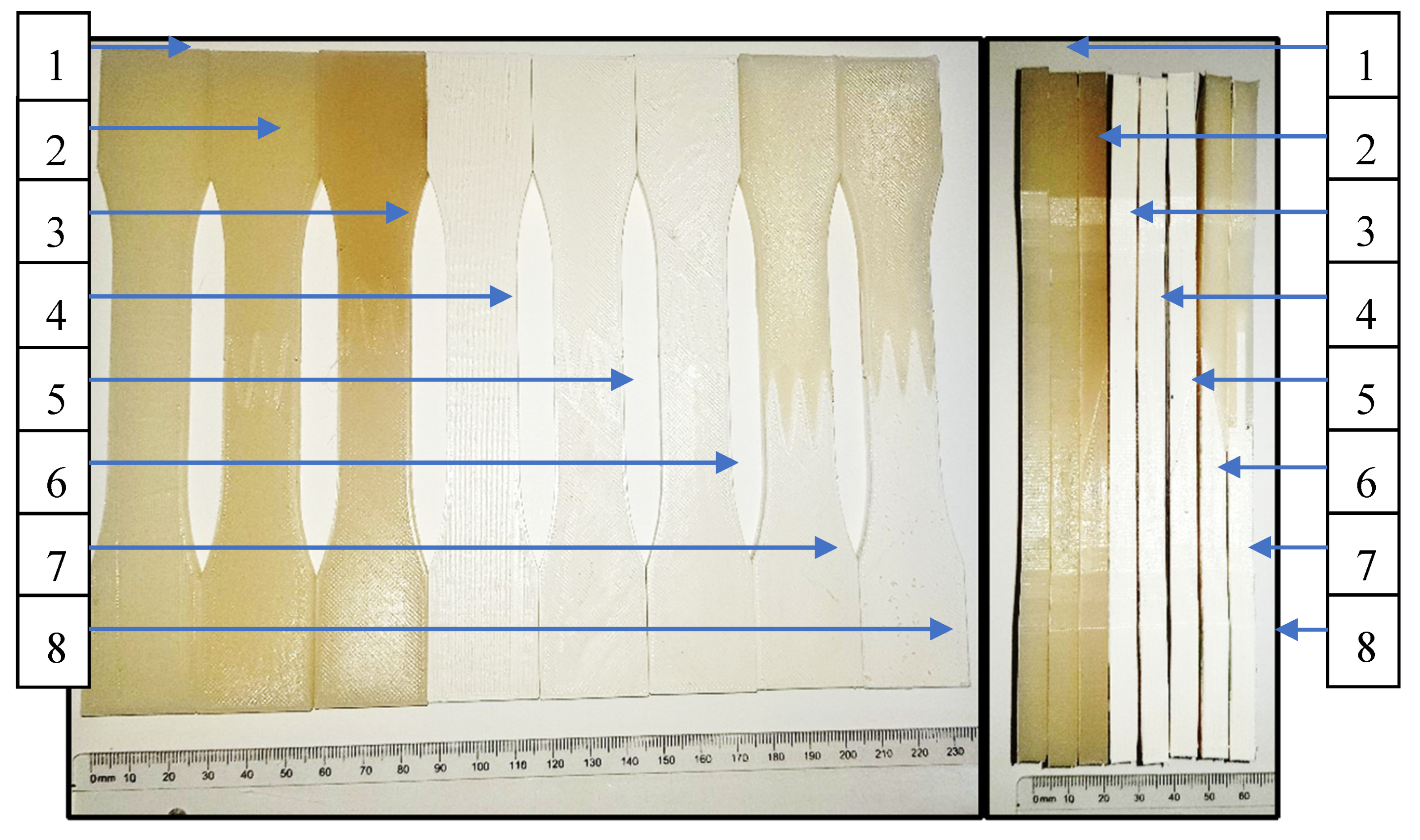
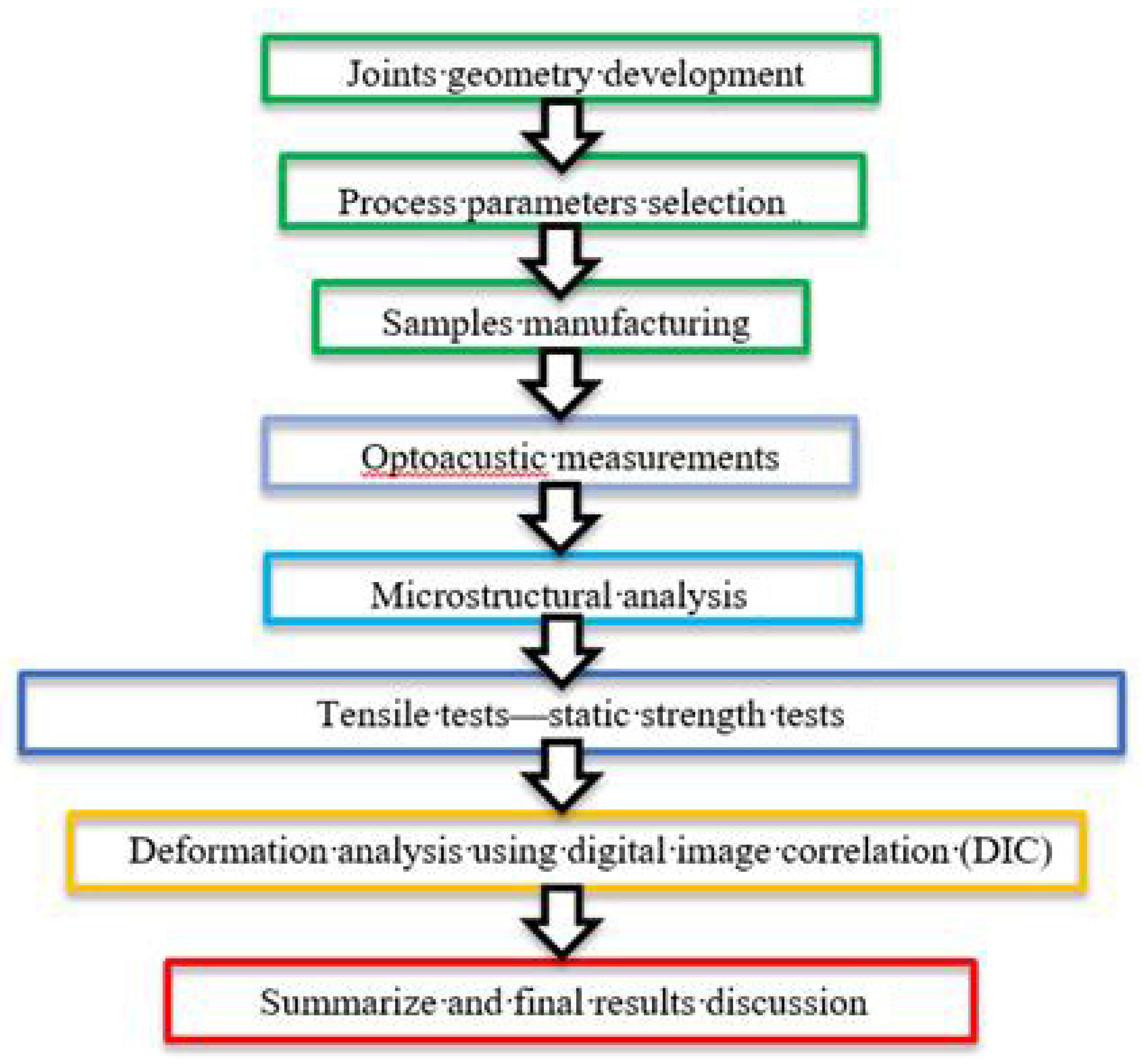
2. Experimental
- Hotend temperature (for both materials): 255 °C,
- Heatbed temperature: 75 °C,
- Layer thickness: 0.2 mm,
- Infill: 100%,
- Part cooling intensity: 40%,
- Printing speed: 50 mm/s,
- Nozzle diameter: 0.4 mm,
- Distance between extruded paths: 0.36 mm.
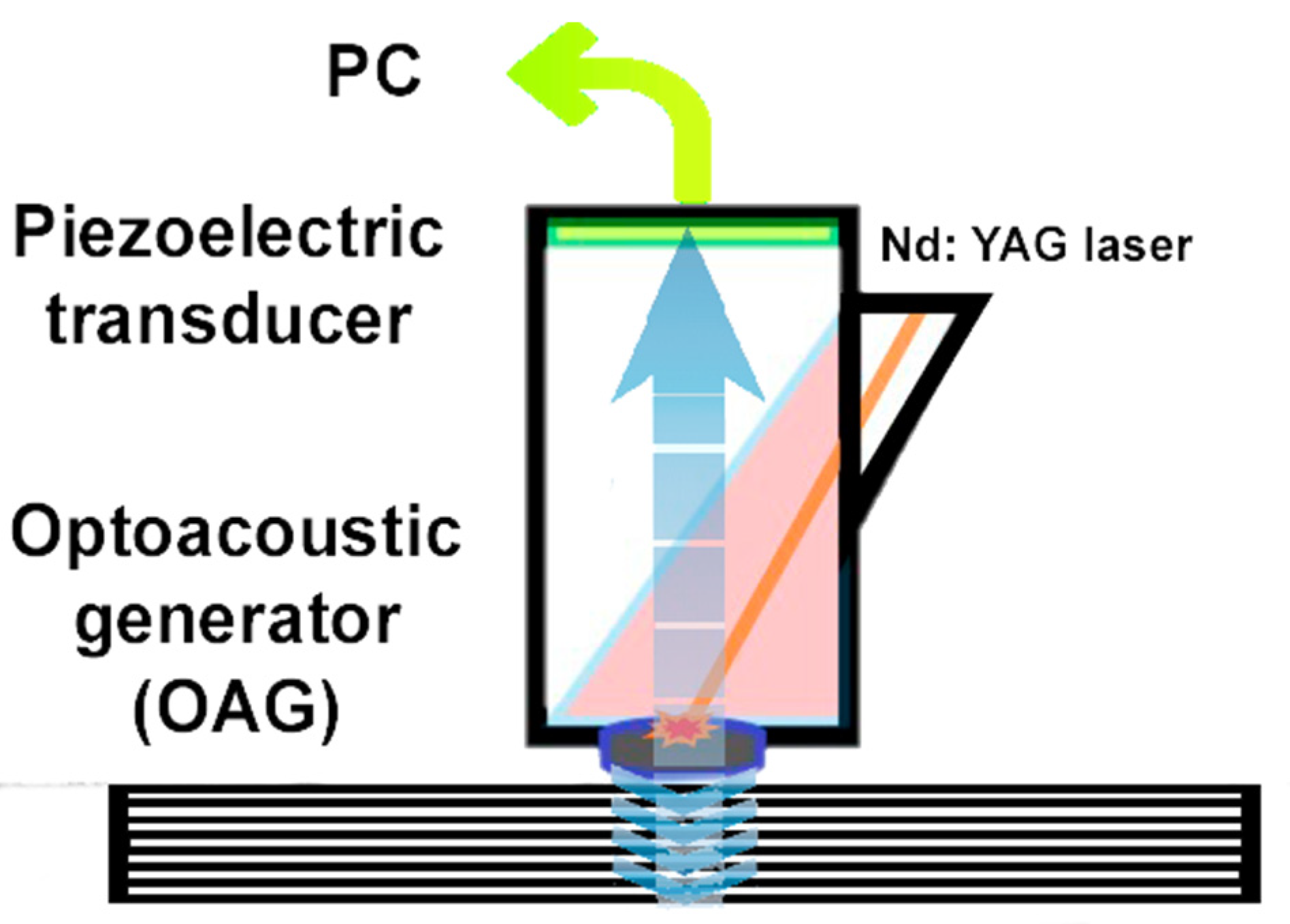
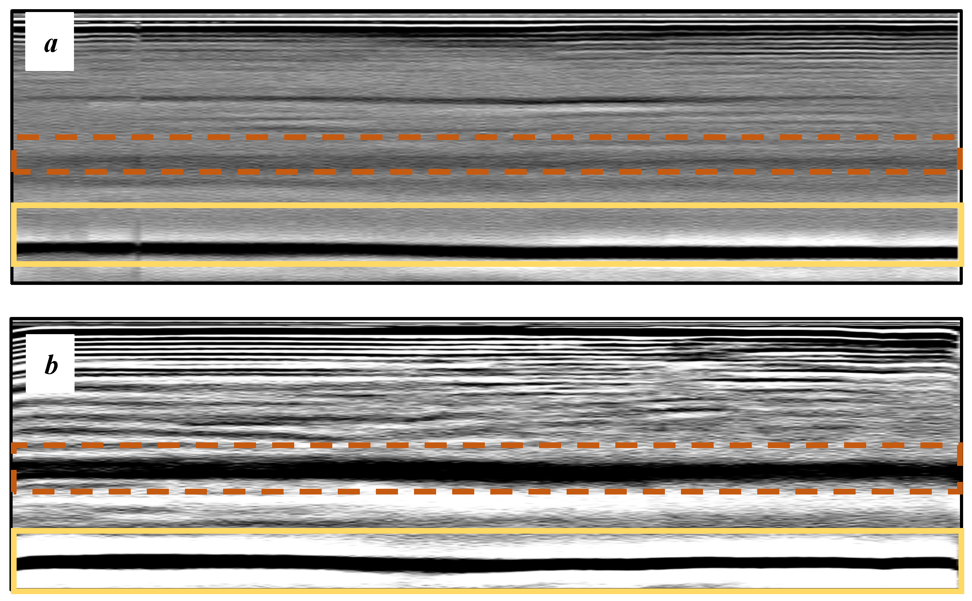
3. Optoacoustic Equipment and Measuring Technique Results and Discussion
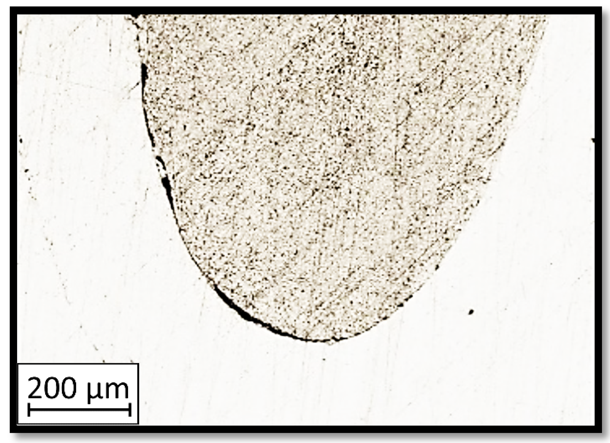
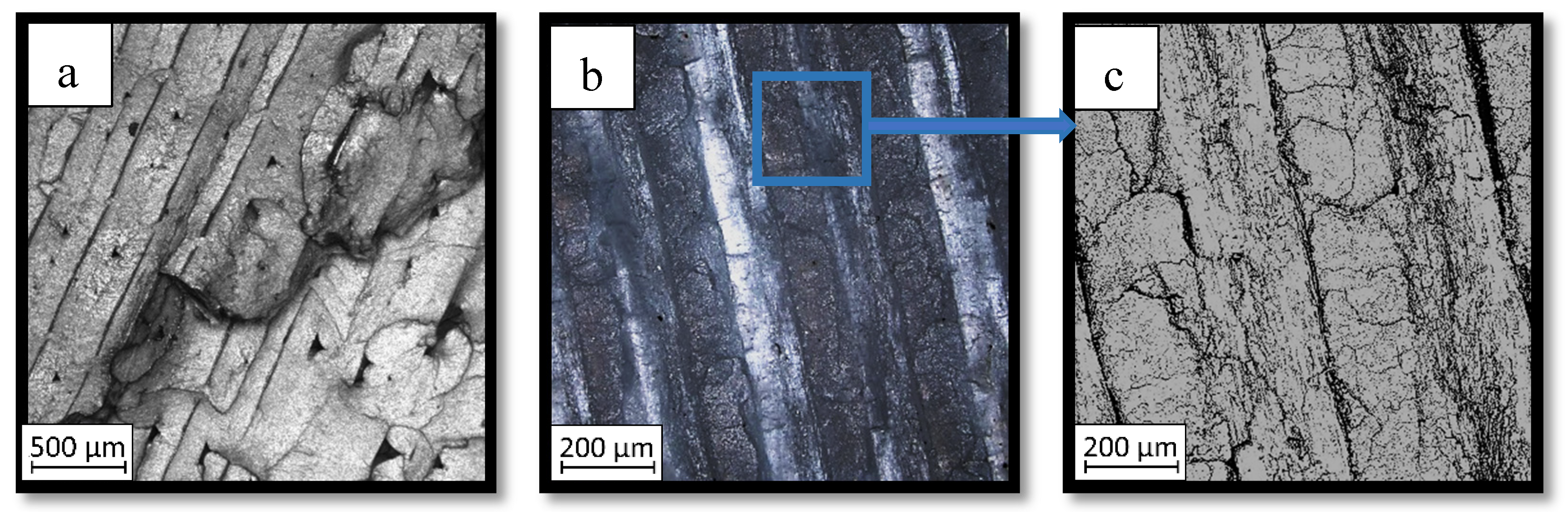
4. Microstructural Analysis—Results and Discussion
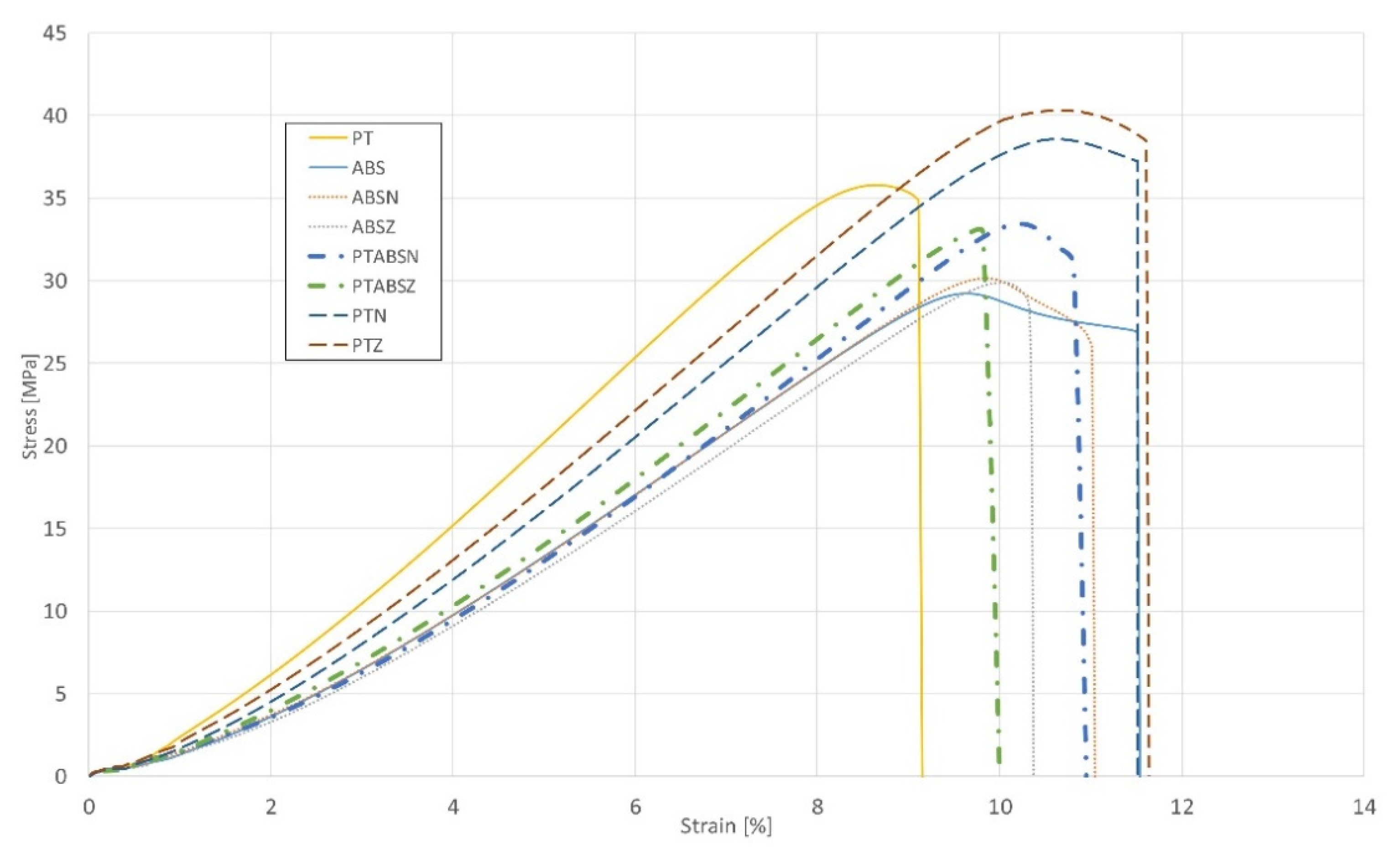
5. Tensile Test—Results and Discussion
6. Final Conclusions
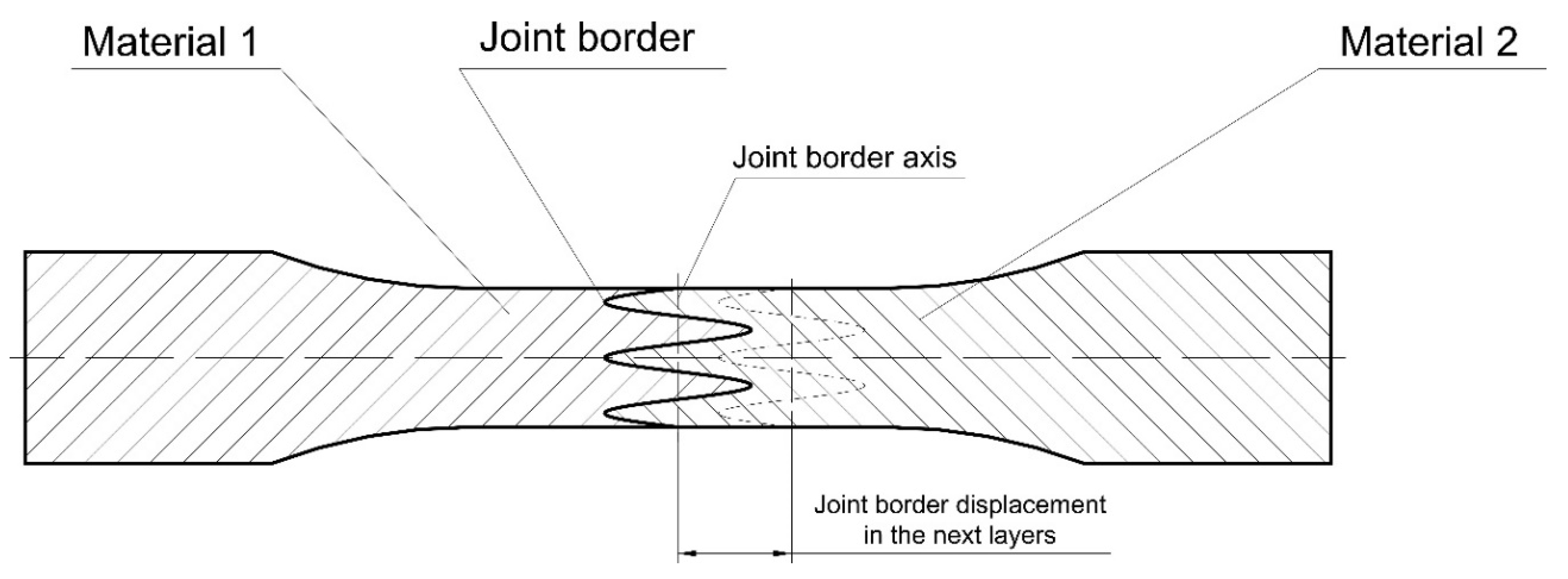
- The study revealed that the samples with an “overlap” joint have greater strength than specimens with a “smooth” joint. This is due to the larger contact area, plane-parallel connection geometry and double nature of the material strength at the joint borders.
- Contact laser ultrasound spectroscopy can be used to visualize the internal structure of composite materials. It is also possible to control the quality of special joints and detect internal defects to evaluate the number and thickness of layers of PLA and ABS plastics.
- The use of “shaped-adhesive” connections allows elements with different properties to be obtained, depending on the materials used.
- The developed method is a real alternative to glued joints with this type of material.
- The method is proper for the connection of all 3D-printable materials, including elastomers and materials with the addition of metal and ceramic powders.
- In relation to solutions in the literature, the investigated technology allows for better joint properties to be obtained than presented in the paper [3].
- To achieve a better performance of the obtained joints, heat treatment could be helpful and will be used in further research.
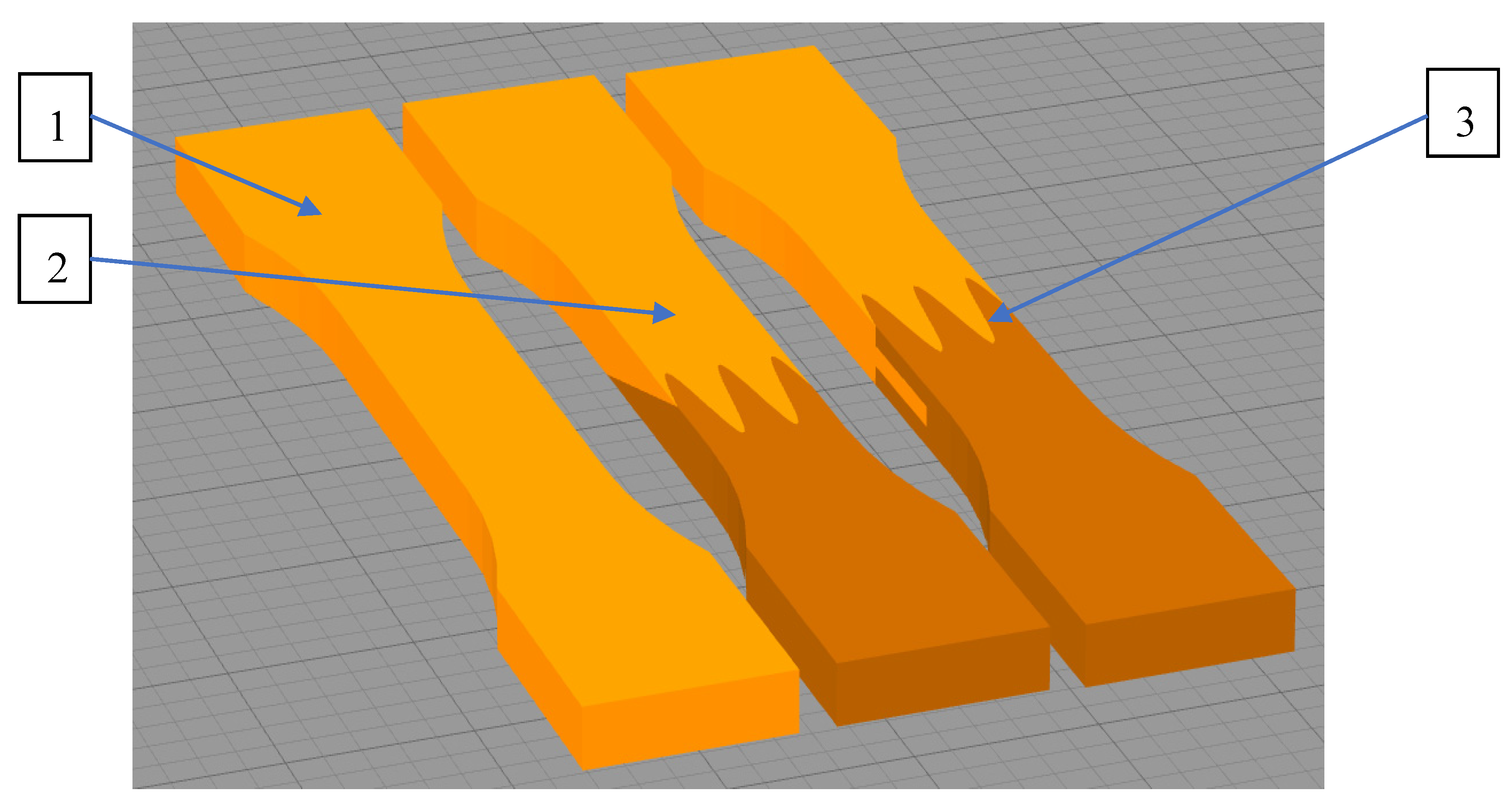
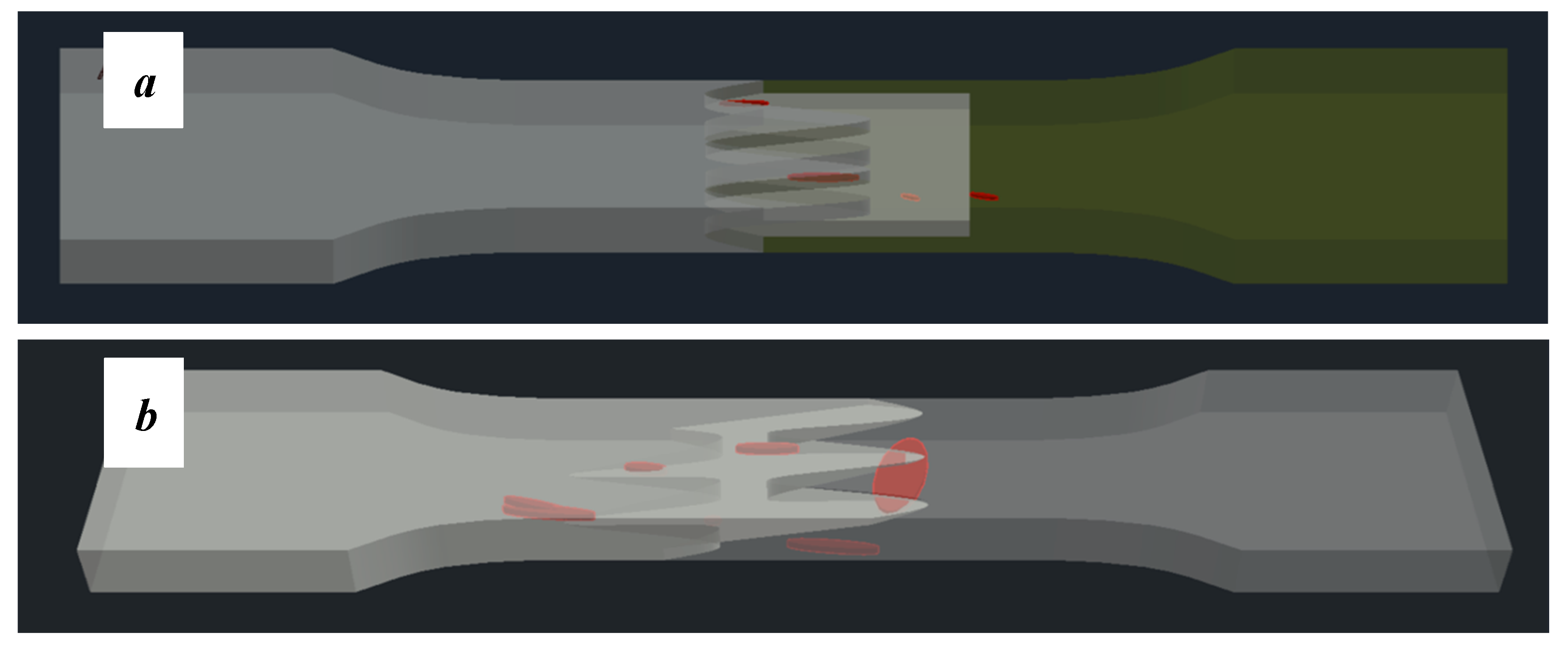
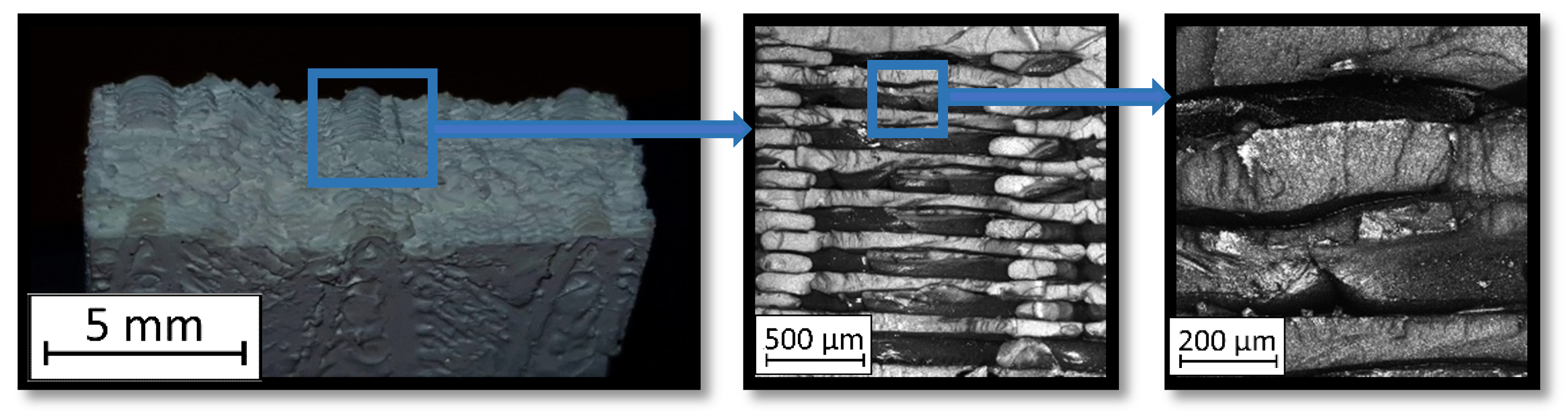
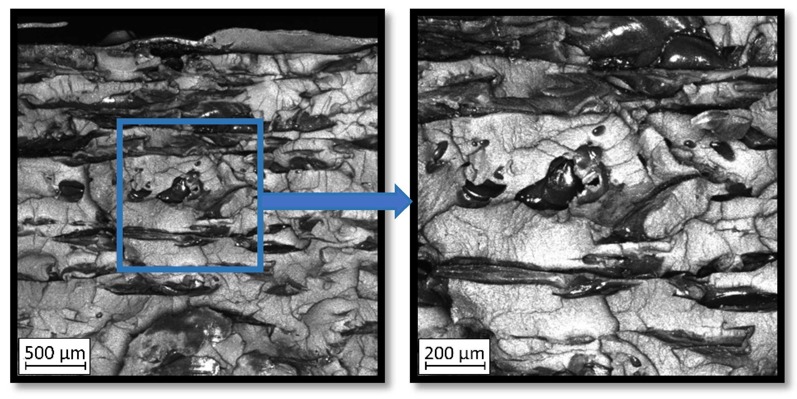
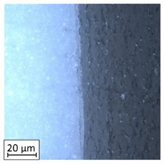
- The pleated connection areas are characterized by both materials (PLA and ABS) penetration, where one material came into another material surface irregularities. Investigated connection geometry and manufacturing techniques allow for materials overlapping which were connected with lowering the distance between the extrusion path.
- The overlap connection between both parts made of PLA increased the specimen’s tensile strength by 2.3% with the increase of the strain at the break by 21%.
- The pleated joint of both parts made of PLA (PTZ) allowed increasing the tensile strength by 14% with increasing the elongation of the material by 22%.
- In both connection types of ABS parts, its tensile strength increased (5% for overlap connection—ABSN, and 2% for pleated connection—ABSZ). At the same time, elongation at break decreased (4% for overlap connection—ABSN, and 11% for pleated connection—ABSZ).
Author Contributions
Funding
Acknowledgments
Conflicts of Interest
References
- Madhavan Nampoothiri, K.; Nair, N.R.; John, R.P. An overview of the recent developments in polylactide (PLA) research. Bioresour. Technol. 2010, 101, 8493–8501. [Google Scholar] [CrossRef] [PubMed]
- Ahmed, J.; Varshney, S.K. Polylactides-chemistry, properties and green packaging technology: A review. Int. J. Food Prop. 2011, 14, 37–58. [Google Scholar] [CrossRef]
- Kovan, V.; Altan, G.; Topal, E.S. Effect of layer thickness and print orientation on strength of 3D printed and adhesively bonded single lap joints. J. Mech. Sci. Technol. 2017, 31, 2197–2201. [Google Scholar] [CrossRef]
- Cicala, G.; Giordano, D.; Tosto, C.; Filippone, G.; Recca, A.; Blanco, I. Polylactide (PLA) filaments a biobased solution for additive manufacturing: Correlating rheology and thermomechanical properties with printing quality. Materials 2018, 11, 1191. [Google Scholar] [CrossRef] [Green Version]
- Coppola, B.; Cappetti, N.; Di Maio, L.; Scarfato, P.; Incarnato, L. 3D printing of PLA/clay nanocomposites: Influence of printing temperature on printed samples properties. Materials 2018, 11, 1947. [Google Scholar] [CrossRef] [Green Version]
- Kucewicz, M.; Baranowski, P.; Stankiewicz, M.; Konarzewski, M.; Płatek, P.; Małachowski, J. Modelling and testing of 3D printed cellular structures under quasi-static and dynamic conditions. Thin-Walled Struct. 2019, 145, 106385. [Google Scholar] [CrossRef]
- Kucewicz, M.; Baranowski, P.; Małachowski, J.; Popławski, A.; Płatek, P. Modelling, and characterization of 3D printed cellular structures. Mater. Des. 2018, 142, 177–189. [Google Scholar] [CrossRef]
- Li, Y.; Shimizu, H. Co-continuous polyamide 6 (PA6)/Acrylonitrile-Butadiene-Styrene (ABS) nanocomposites. Macromol. Rapid Commun. 2005, 26, 710–715. [Google Scholar] [CrossRef]
- Choe, I.J.; Lee, J.H.; Yu, J.H.; Yoon, J.S. Mechanical properties of acrylonitrile-butadiene-styrene copolymer/poly(l-lactic acid) blends and their composites. J. Appl. Polym. Sci. 2014, 131, 1–8. [Google Scholar] [CrossRef]
- Stanzione, J.; La Scala, J. Sustainable polymers and polymer science: Dedicated to the life and work of Richard P. Wool. J. Appl. Polym. Sci. 2016, 133. [Google Scholar] [CrossRef]
- Oleksy, M.; Budzik, G.; Kozik, B.; Gardzinska, A. Hybrydowe nanokompozyty polimerowe stosowane w technologii Rapid Prototyping. Polim. Polym. 2017, 62, 3–10. [Google Scholar] [CrossRef]
- du Plessis, A.; Broeckhoven, C.; Yadroitsava, I.; Yadroitsev, I.; Hands, C.H.; Kunju, R.; Bhate, D. Beautiful and Functional: A Review of Biomimetic Design in Additive Manufacturing. Addit. Manuf. 2019, 27, 408–427. [Google Scholar] [CrossRef]
- Shin, D.G.; Kim, T.H.; Kim, D.E. Review of 4D printing materials and their properties. Int. J. Precis. Eng. Manuf. Green Technol. 2017, 4, 349–357. [Google Scholar] [CrossRef]
- Hardin, J.O.; Ober, T.J.; Valentine, A.D.; Lewis, J.A. Microfluidic printheads for multimaterial 3D printing of viscoelastic inks. Adv. Mater. 2015, 27, 3279–3284. [Google Scholar] [CrossRef]
- Chen, D.; Zheng, X. Multi-material Additive Manufacturing of Metamaterials with Giant, Tailorable Negative Poisson’s Ratios. Sci. Rep. 2018, 8, 9139. [Google Scholar] [CrossRef]
- Alssabbagh, M.; Tajuddin, A.A.; Abdulmanap, M.; Zainon, R. Evaluation of 3D printing materials for fabrication of a novel multi-functional 3D thyroid phantom for medical dosimetry and image quality. Radiat. Phys. Chem. 2017, 135, 106–112. [Google Scholar] [CrossRef]
- Goh, G.D.; Dikshit, V.; Nagalingam, A.P.; Goh, G.L.; Agarwala, S.; Sing, S.L.; Wei, J.; Yeong, W.Y. Characterization of mechanical properties and fracture mode of additively manufactured carbon fiber and glass fiber reinforced thermoplastics. Mater. Des. 2018, 137, 79–89. [Google Scholar] [CrossRef]
- Singh, R.; Kumar, R.; Feo, L.; Fraternali, F. Friction welding of dissimilar plastic/polymer materials with metal powder reinforcement for engineering applications. Compos. Part B Eng. 2016, 101, 77–86. [Google Scholar] [CrossRef]
- Smutek, P.; Witkowski, W.; Przeszłowski, Ł. Epoxy adhesives use for connecting components made by rapid prototyping. In Przegląd Mechaniczny; SIGMA-NOT Sp. Z o.o.: Warsaw, Poland, 2018; pp. 29–32. [Google Scholar]
- Lopes, L.R.; Silva, A.F.; Carneiro, O.S. Multi-material 3D printing: The relevance of materials affinity on the boundary interface performance. Addit. Manuf. 2018, 23, 45–52. [Google Scholar] [CrossRef]
- Kim, H.B.; Naito, K.; Oguma, H. Fatigue crack growth properties of a two-part acrylic-based adhesive in an adhesive bonded joint: Double cantilever-beam tests under Mode I loading. Int. J. Fatigue 2017, 98, 286–295. [Google Scholar] [CrossRef]
- Kaner, S.; Sekercioglu, T. Effect of Surface Pre-treatments and Ageing on the Adhesive Strength of Polymer Joints. Polymer (Korea) 2017, 41, 827–834. [Google Scholar] [CrossRef]
- Zhao, K.; Xu, L.R. Size Effect of the Adhesive Bonding Strengths of Metal/Polymer Similar and Dissimilar Material Joints. J. Adhes. 2015, 91, 978–991. [Google Scholar] [CrossRef]
- Eslami, S.; Mourão, L.; Viriato, N.; Tavares, P.; Moreira, P.M.G.P. Multi-axis force measurements of polymer friction stir welding. J. Mater. Process. Technol. 2018, 256, 51–56. [Google Scholar] [CrossRef]
- Available online: https://www.materialise.com/sites/default/files/image-uploads/pages/Manufacturing/Technologies/FDM/FDM-3-compressor.png (accessed on 20 December 2019).
- Dvořák, P.; Štoller, J.; Baláž, T.; Krejčí, J. Non-destructive Testing of Critical Infrastructure Objects. In Transport Means; Kaunas University of Technology: Kaunas, Lithuania, 2018; pp. 855–859. [Google Scholar]
- Dvořák, P.; Štoller, J. Ultrasound Diagnosis of Protective Structures after Contact Explosion. In Transport Means; Kaunas University of Technology: Kaunas, Lithuania, 2014; pp. 264–267. [Google Scholar]
- Štoller, J.; Zezulova, E. Use of ultrasound-The ultrasonic pulse velocity method for the diagnosis of protective structures after the load of TNT explosion. In Proceedings of the 2017 International Conference on Military Technologies (ICMT), Brno, Czech Republic, 31 May–2 June 2017; pp. 230–235. [Google Scholar]
- Svoboda, P.; Kravcov, A.; Pospíchal, V.; Morozov, N.; Zezulová, E. Quality assessment of bored pile foundations by a set of non-destructive testing methods. In Proceedings of the 2019 International Conference on Military Technologies (ICMT), Brno, Czech Republic, 30–31 May 2019; pp. 87–91. [Google Scholar]
- Kravcov, A.; Shibaev, I. Examination of structural members of aerial vehicles by laser ultrasonic structuroscopy. Int. J. Civ. Eng. Technol. 2018, 9, 2258–2265. [Google Scholar]
- Kravcov, A.; Platek, P.; Pospichal, V.; Koperski, W. Internal structure research of 3D printed cellular structures by laser-ultrasonic structuroscopy. In Proceedings of the 2019 International Conference on Military Technologies (ICMT), Brno, Czech Republic, 30–31 May 2019; pp. 92–99. [Google Scholar]


| Material | PLA (wt.%) | Material | ABS (wt.%) |
|---|---|---|---|
| Polylactide resin | >75 | Acrylonitrile | 15–35 |
| Magnesium Silicate | <25 | Butadiene | 5–30 |
| Additional Blends | ≈3 | Styrene | 40–60 |
| Overlap Connection—Side View | Pleated Connection—Side View | Pleated/Overlap Connection—Front View |
|---|---|---|
 |  |  |
| Tensile Tests Results | PT | ABS | PTN | PTZ | ABSN | ABSZ | PTABSZ | PTABSN |
|---|---|---|---|---|---|---|---|---|
| Ultimate stress (MPa) | 35.8 | 29.4 | 38.6 | 41.3 | 30.8 | 29.9 | 32.7 | 33.4 |
| Strain at break (%) | 9.15 | 11.5 | 11.5 | 11.6 | 11.01 | 10.34 | 10.1 | 11.0 |
| Specimen Description | Strain at 0.2% of Elongation | Strain at Rm | Strain at Ru | Strain at Break | Scale |
|---|---|---|---|---|---|
| ABS | 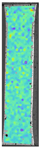 | 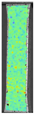 |  |  |  |
| PT |  | 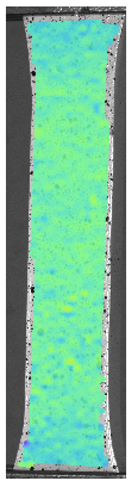 |  |  |  |
| ASN | 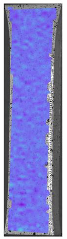 | 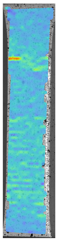 | 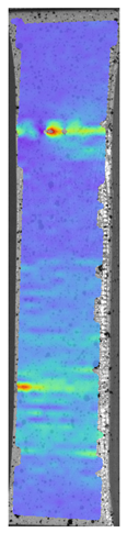 | 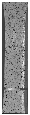 | 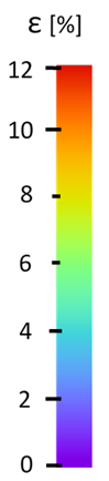 |
| ASZ |  |  | 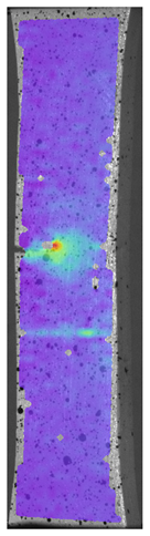 | 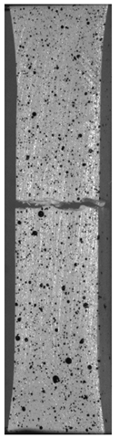 | 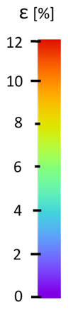 |
| PTN | 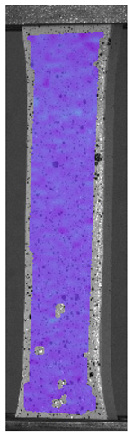 | 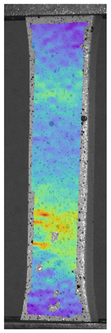 | 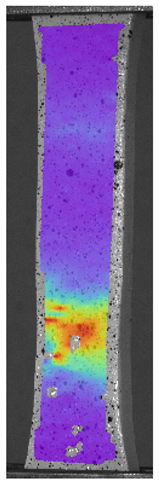 | 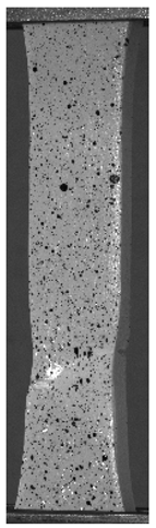 | 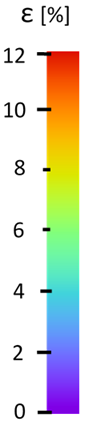 |
| PTZ | 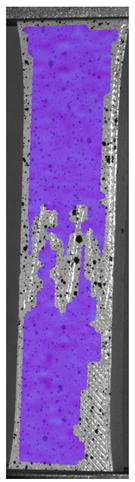 | 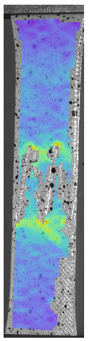 | 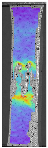 | 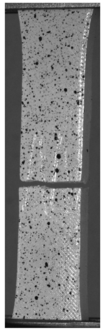 | 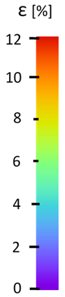 |
| PTASN | 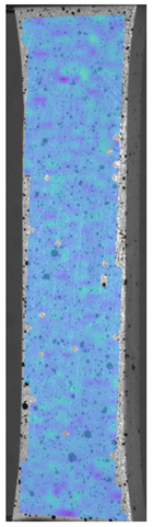 | 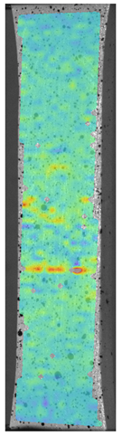 | 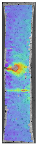 |  | 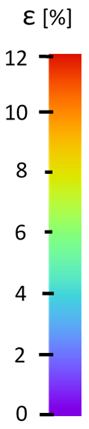 |
| PTASZ |  | 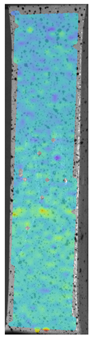 |  |  |  |
© 2020 by the authors. Licensee MDPI, Basel, Switzerland. This article is an open access article distributed under the terms and conditions of the Creative Commons Attribution (CC BY) license (http://creativecommons.org/licenses/by/4.0/).
Share and Cite
Kluczyński, J.; Śnieżek, L.; Kravcov, A.; Grzelak, K.; Svoboda, P.; Szachogłuchowicz, I.; Franek, O.; Morozov, N.; Torzewski, J.; Kubeček, P. The Examination of Restrained Joints Created in the Process of Multi-Material FFF Additive Manufacturing Technology. Materials 2020, 13, 903. https://doi.org/10.3390/ma13040903
Kluczyński J, Śnieżek L, Kravcov A, Grzelak K, Svoboda P, Szachogłuchowicz I, Franek O, Morozov N, Torzewski J, Kubeček P. The Examination of Restrained Joints Created in the Process of Multi-Material FFF Additive Manufacturing Technology. Materials. 2020; 13(4):903. https://doi.org/10.3390/ma13040903
Chicago/Turabian StyleKluczyński, Janusz, Lucjan Śnieżek, Alexander Kravcov, Krzysztof Grzelak, Pavel Svoboda, Ireneusz Szachogłuchowicz, Ondřej Franek, Nikolaj Morozov, Janusz Torzewski, and Petr Kubeček. 2020. "The Examination of Restrained Joints Created in the Process of Multi-Material FFF Additive Manufacturing Technology" Materials 13, no. 4: 903. https://doi.org/10.3390/ma13040903