Obtaining a Wire of Biocompatible Superelastic Alloy Ti–28Nb–5Zr

 , ,
, ,
Abstract
:1. Introduction
2. Materials and Methods
3. Results
4. Discussion
5. Conclusions
- An alloy of the composition Ti–28Nb–5Zr was obtained sequentially in the form of ingots, bars and wire by melting in vacuum electric arc furnaces, intermediate homogenizing annealing, and intensive plastic deformation.
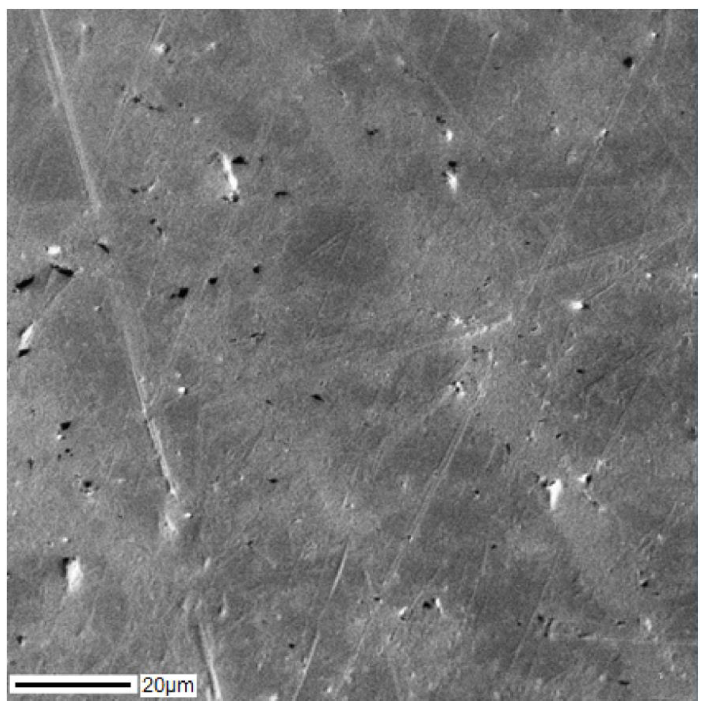
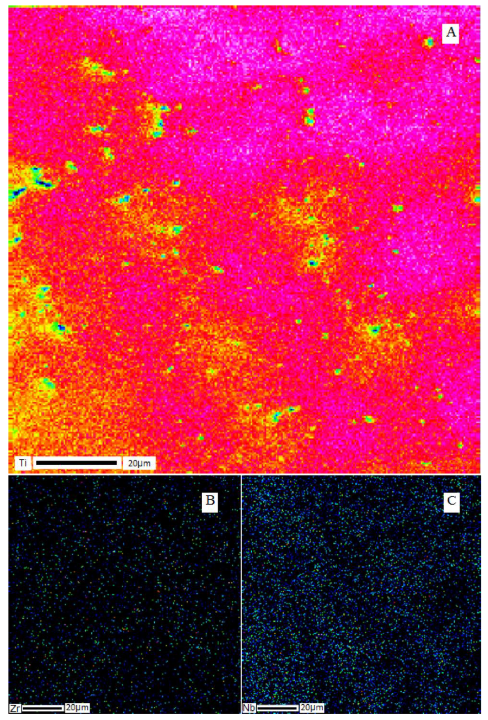
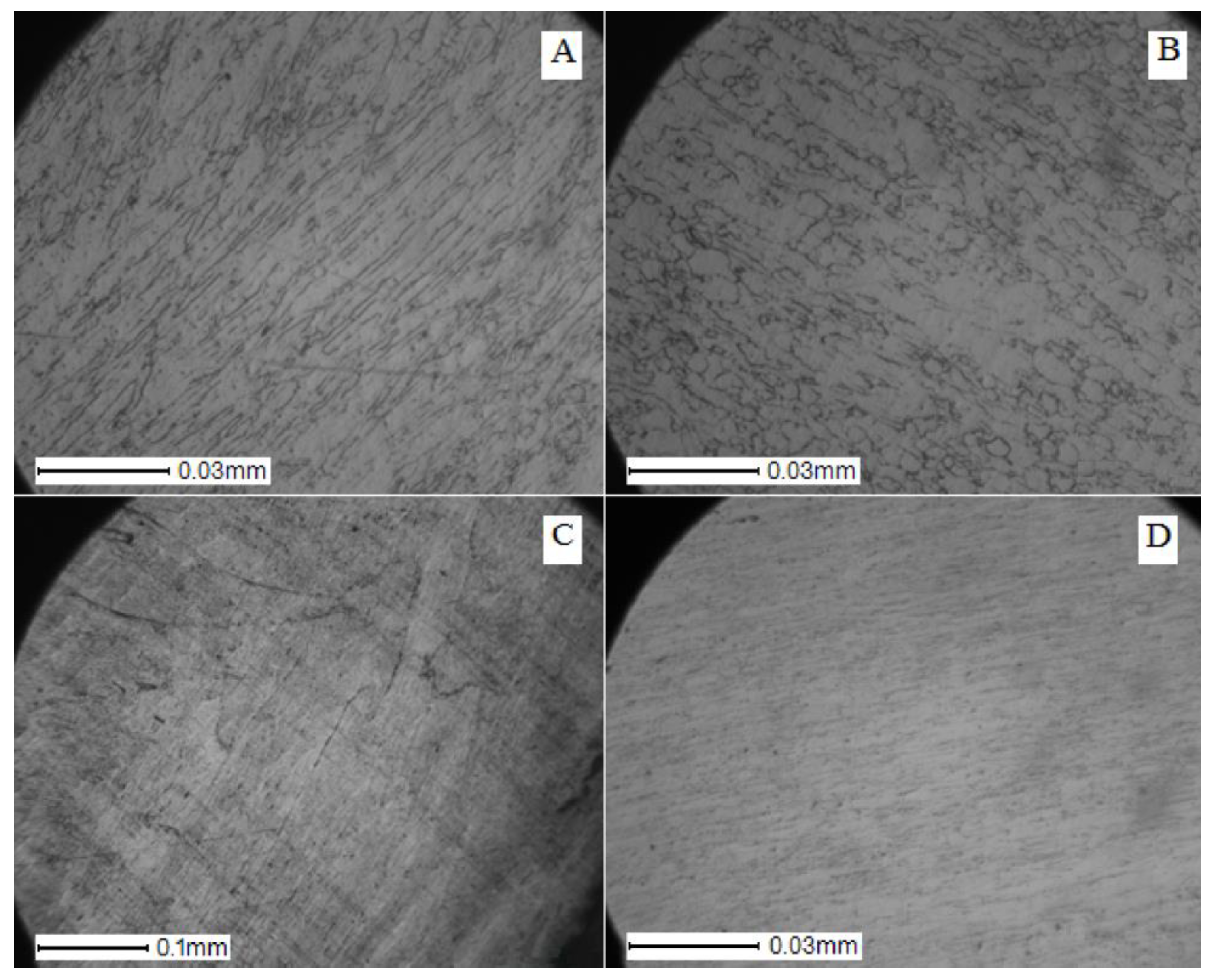
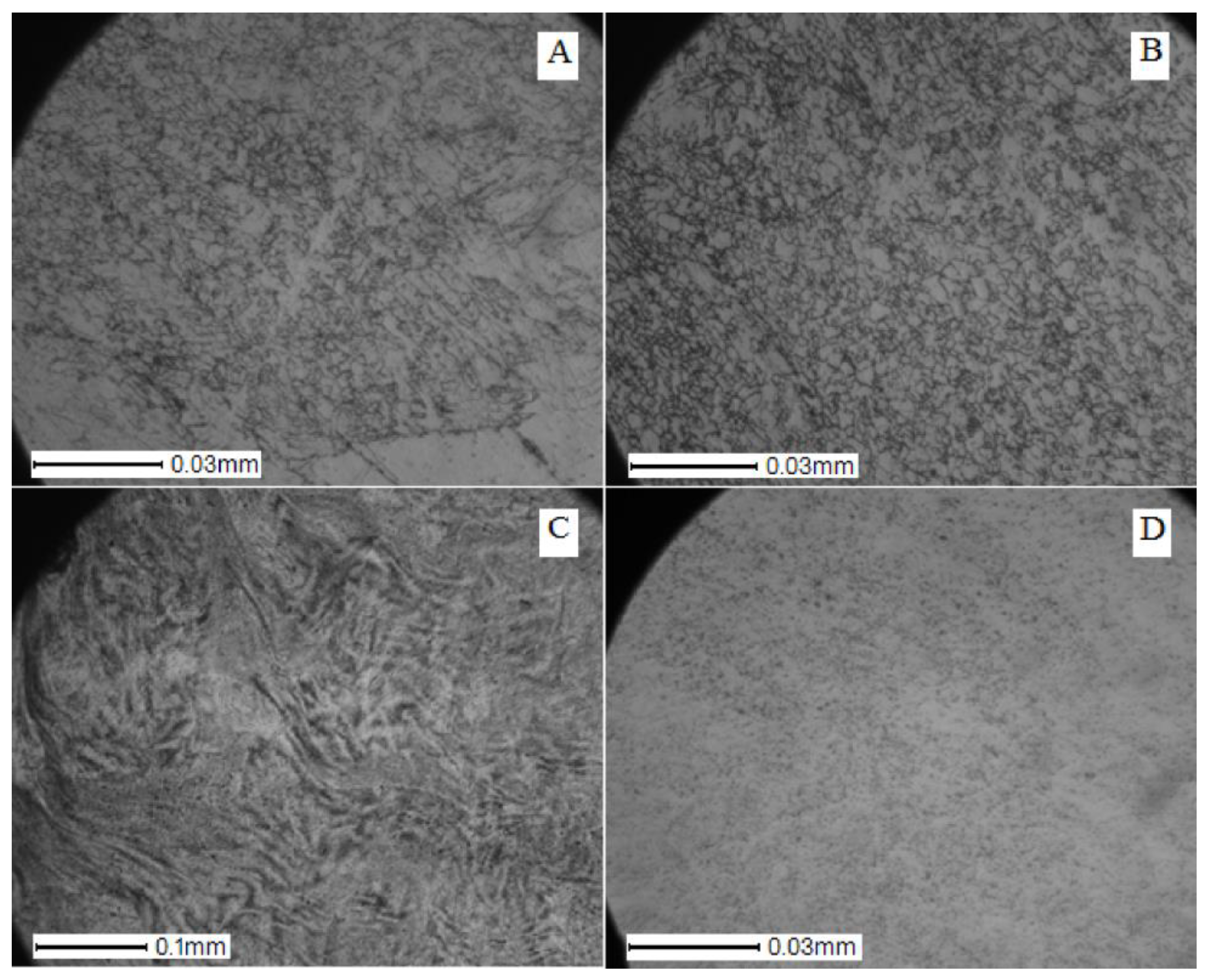
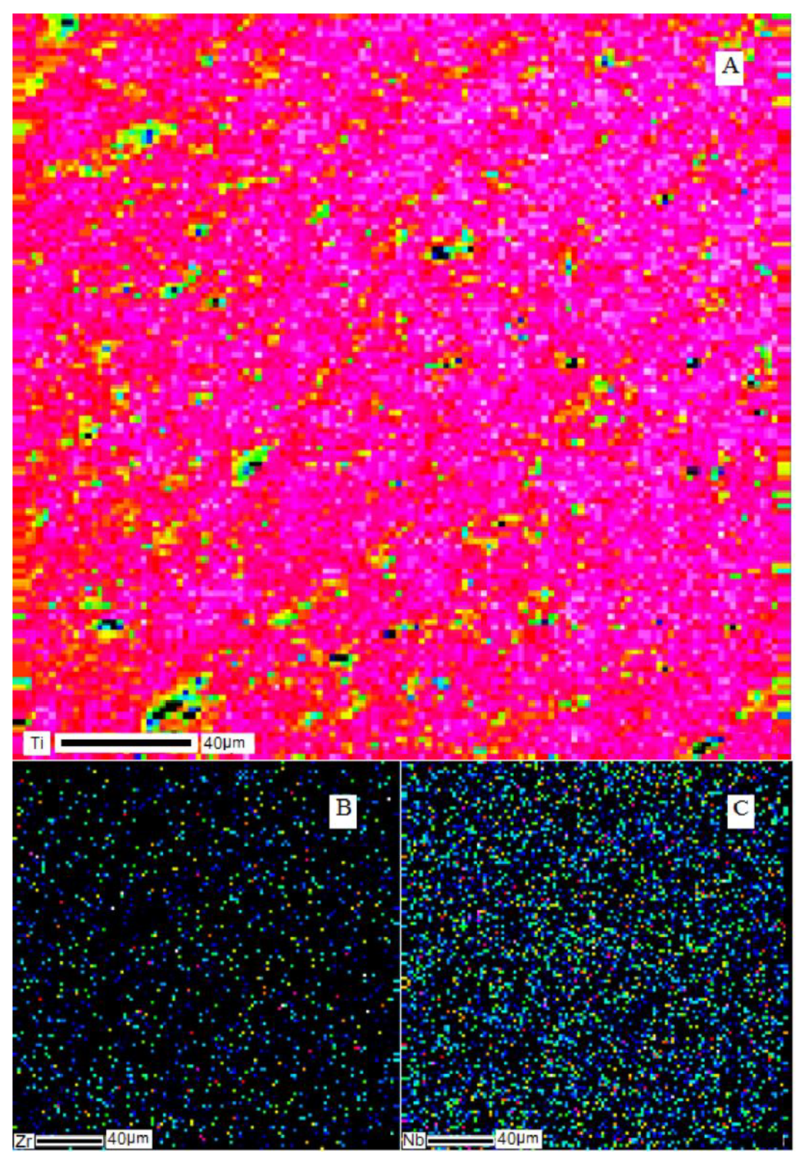
- A uniform distribution of elements over the volume of ingots was noted, as well as a good agreement between the element concentrations obtained in the alloy and the expected calculated values corresponding to the selected weights of charge materials. It was found that a uniform structure was obtained before and after homogenizing annealing. Elements of the alloy are not distributed in it by individual fragments but are connected in a single structure. The ingots have an inherent dendritic structure characteristic for cast alloys.
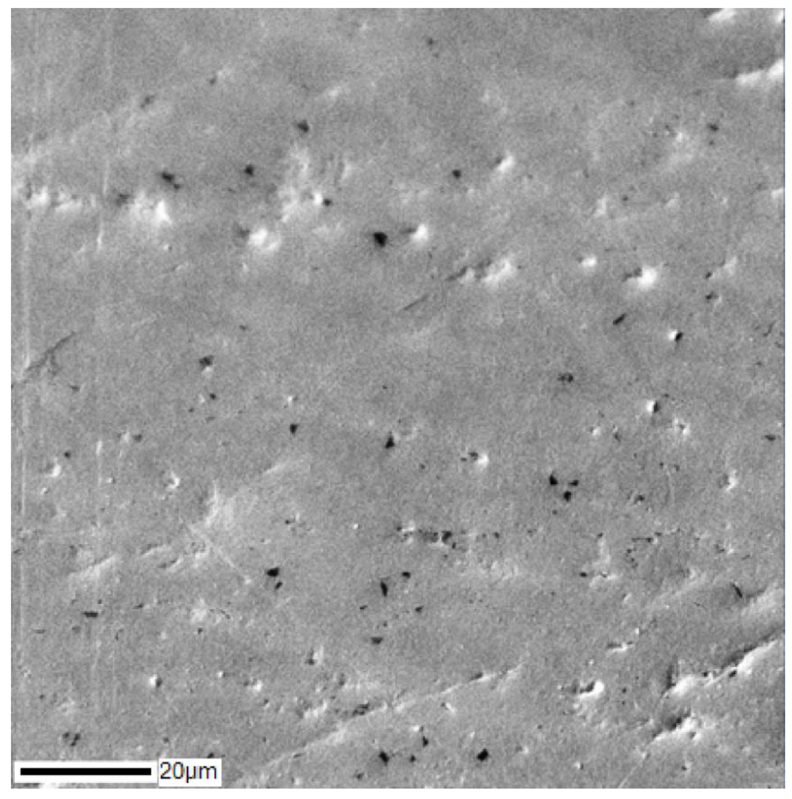
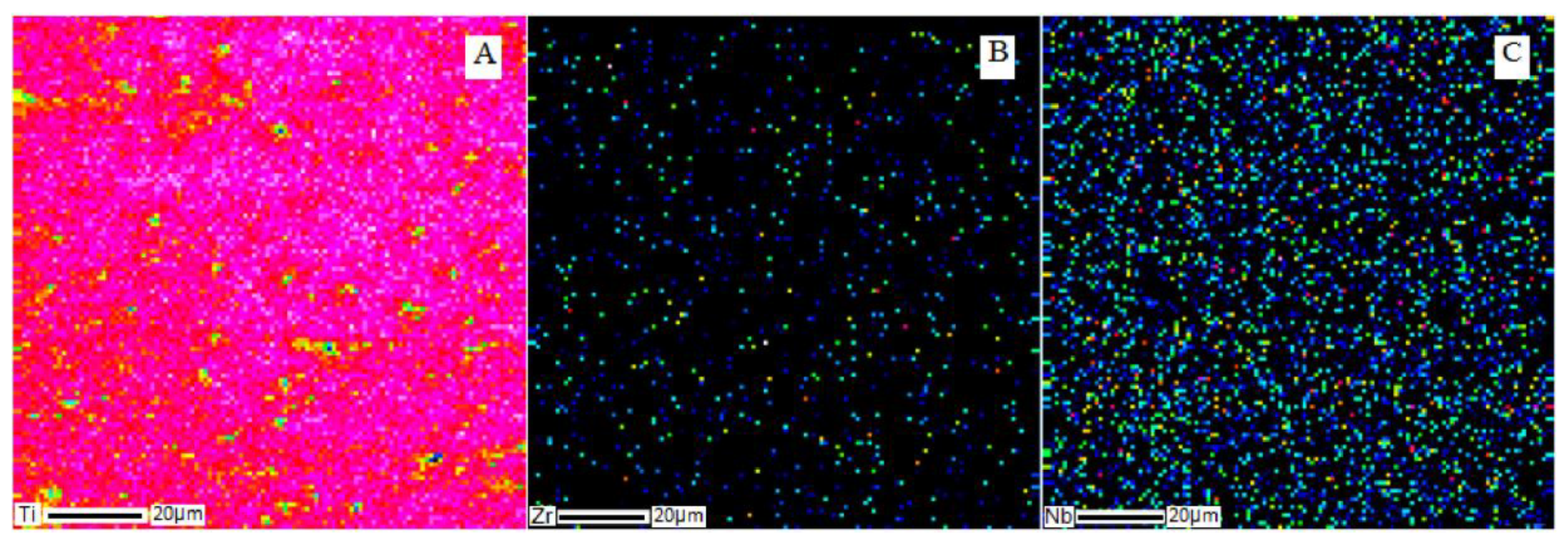
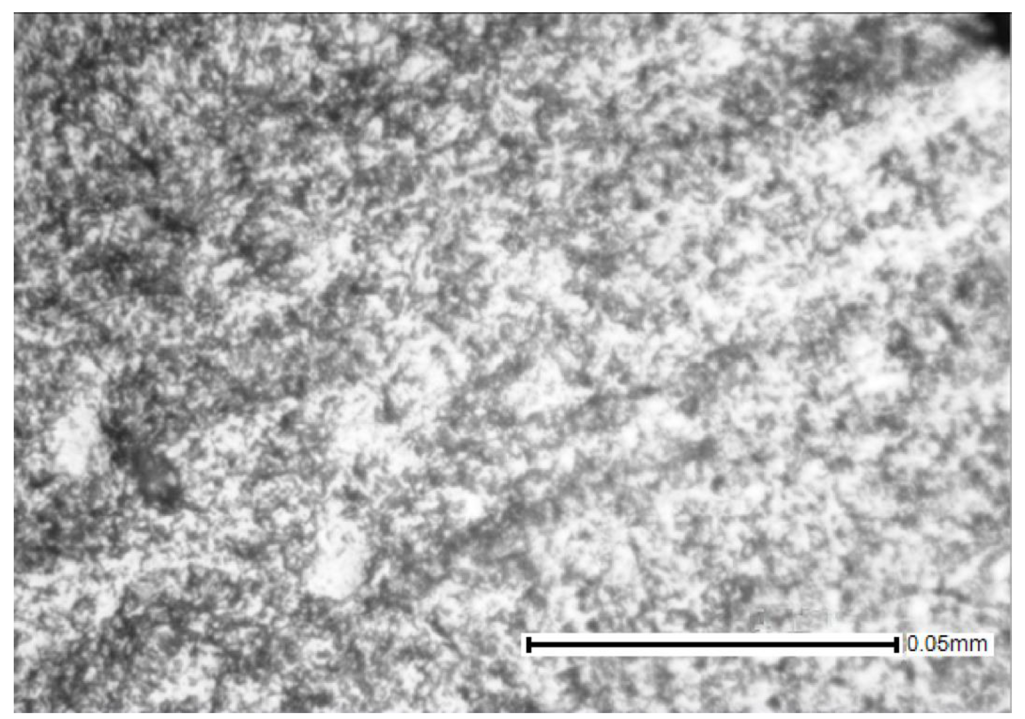
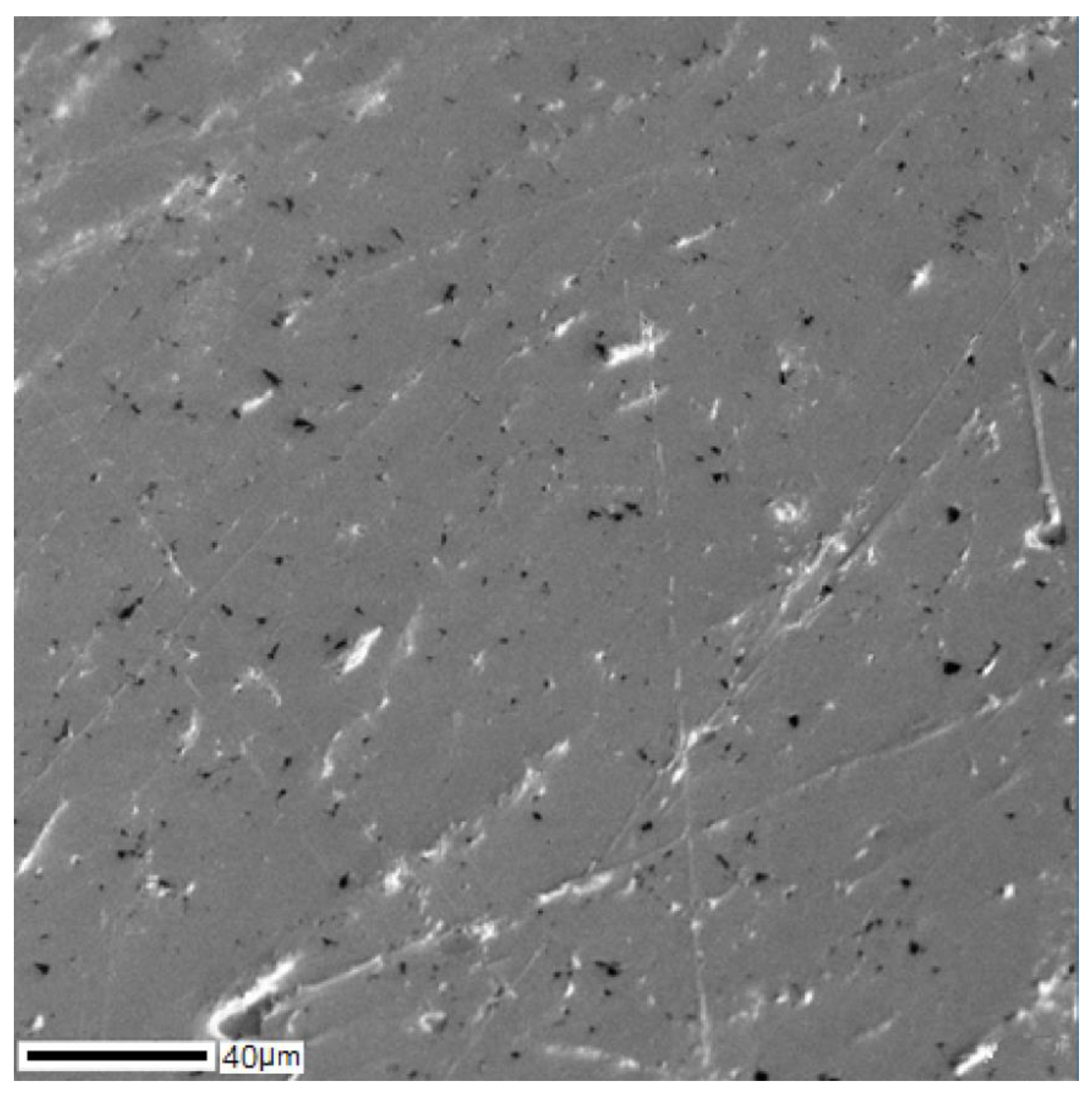
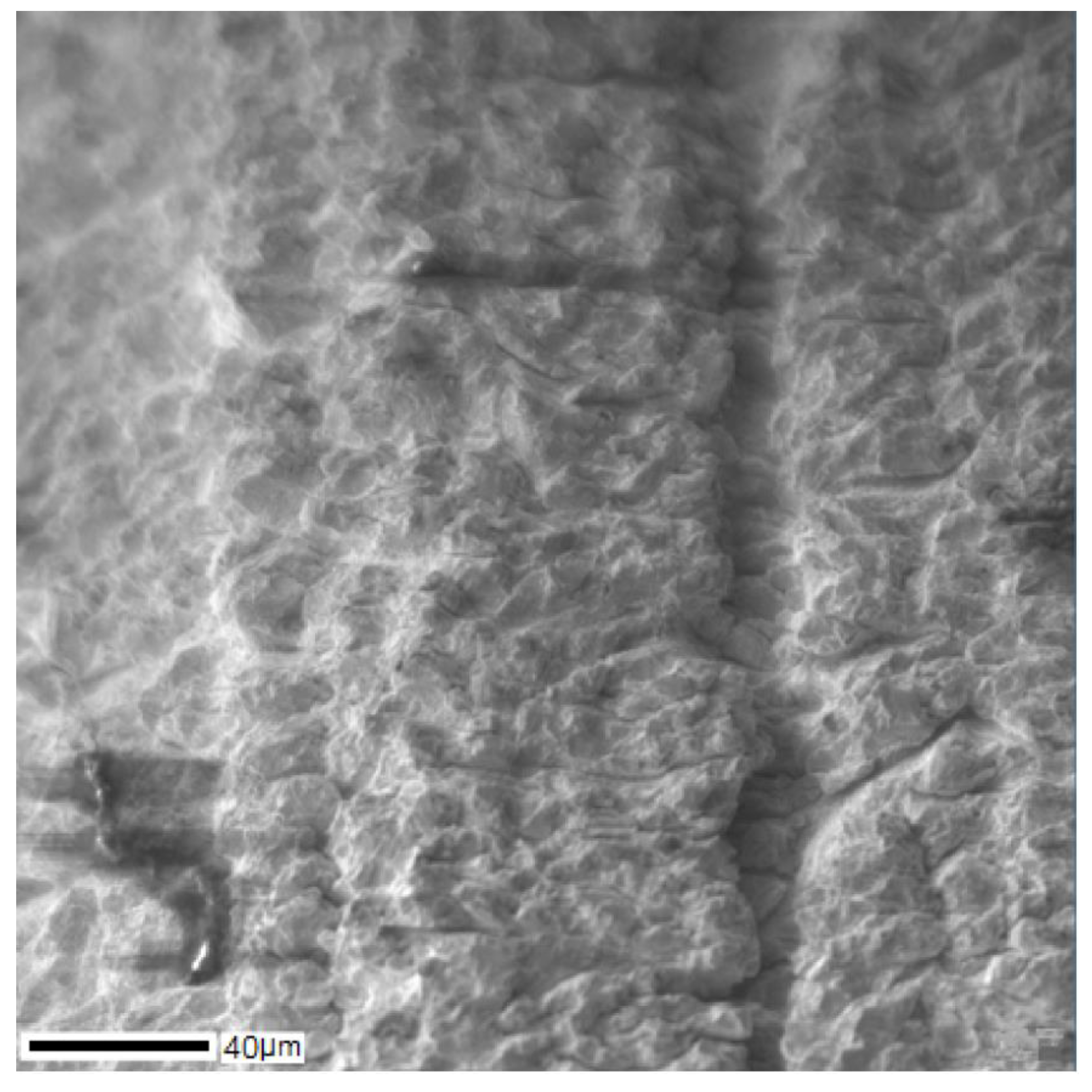
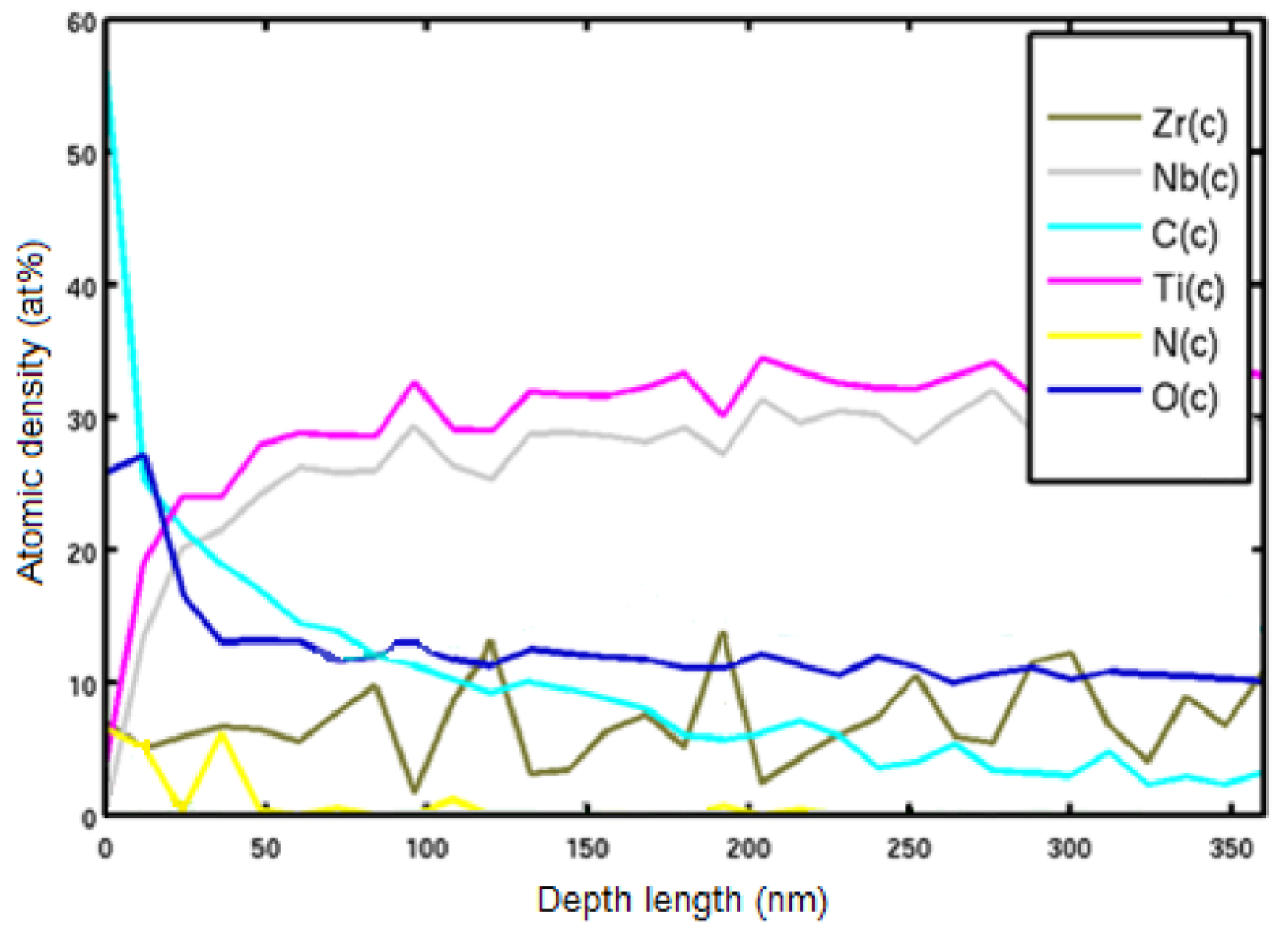
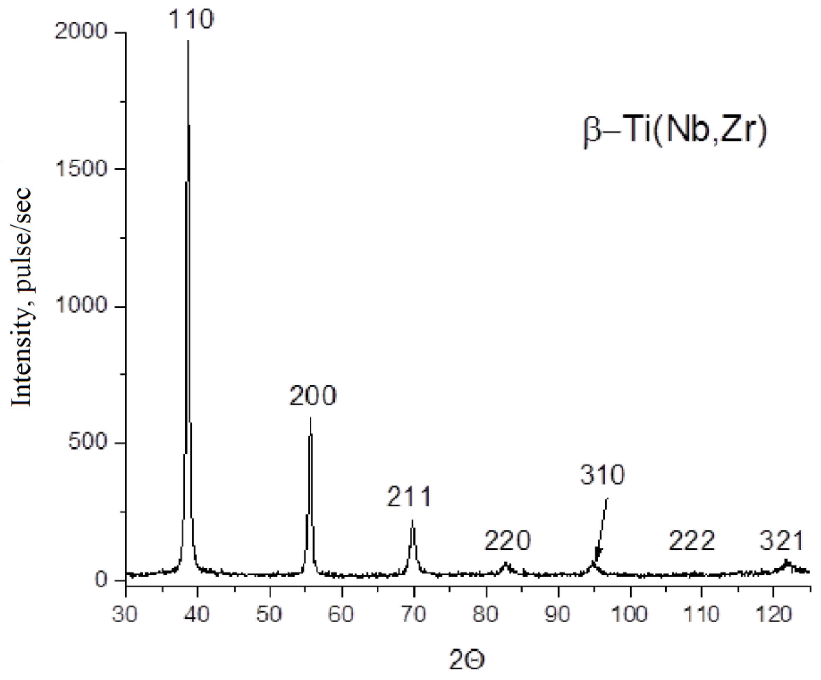
- It was noted that after the plastic deformation of the ingots and annealing at 600 °C in air, the grain boundaries are not visible during microstructural analysis, which indicates the absence of recrystallization. The formation of a nanostructure is possible. The surface morphology of wires after drawing shows a high heterogeneity and roughness. However, in terms of chemical composition to a depth of more than 200 nm, a uniform oxide film without impurities is observed. After grinding the surface, its uniformity increases. All wire samples were single-phase with a β-Ti type crystal lattice (bcc).
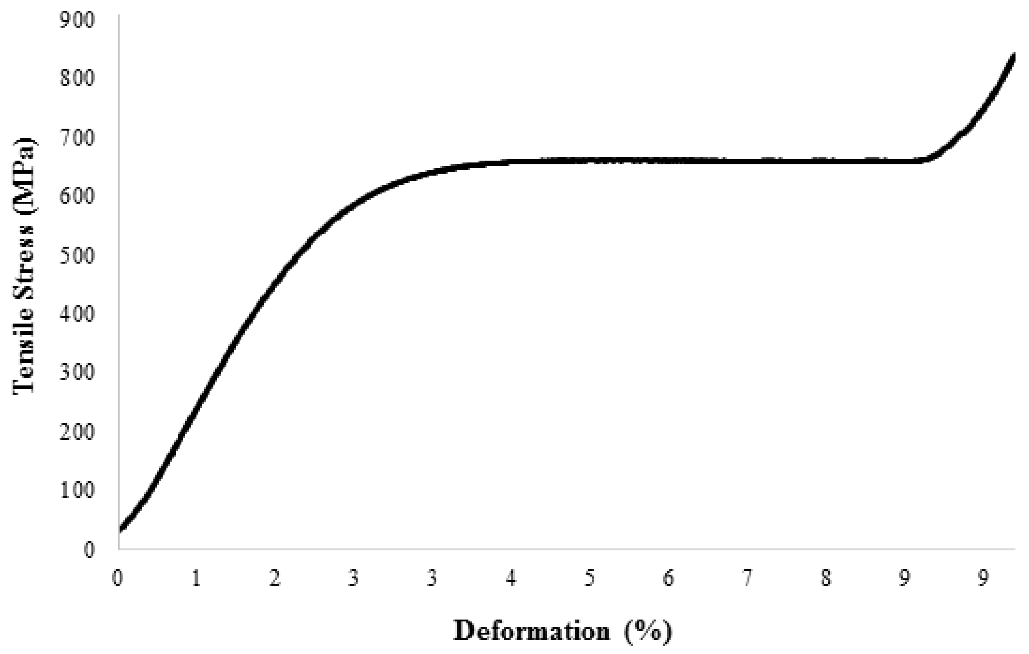
- For the wire obtained after stabilizing annealing, the average proof strength, plastic extension Rp0.2 on the samples was 635 MPa, tensile strength was 840 MPa, Young’s modulus was 22 GPa, and elongation was 6.76%.
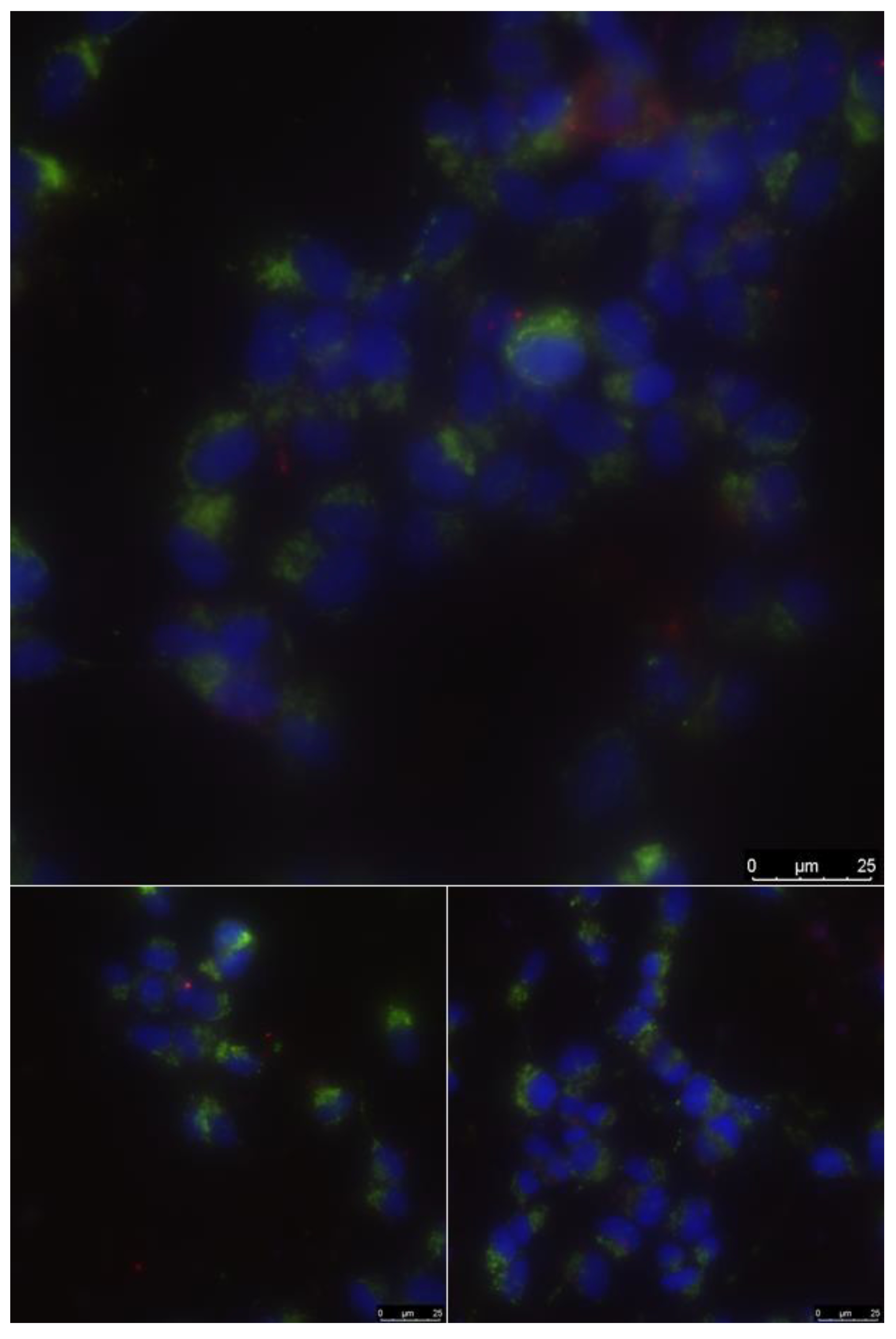
- No toxicity was detected.
- Thus, the use of TiNbZr wire in medicine, for example, for the production of implants, such as stents and cava filters, is promising.
Author Contributions
Funding
Acknowledgments
Conflicts of Interest
References
- Gunther, V.E.; Hodorenko, V.N.; Yasenchuk, Y.F.; Chekalkin, T.L. Nikelid Titana, Meditsynsky Material Novogo Pokoleniya [Titanium Nickelide, Medical Material of New Generation]; MITs Publishing House: Tomsk, Russia, 2006. [Google Scholar]
- Pelton, A.; Huang, G.; Moine, P.; Sinclair, R. Effects of thermal cycling on microstructure and properties in Nitinol. Mater. Sci. Eng. A 2012, 532, 130–138. [Google Scholar] [CrossRef]
- Duerig, T.W.; Melton, K.N.; Wayman, C.M.; Stockel, D. Engineering Aspects of Shape–Memory Alloys; Butterworth Heinemann Ltd.: Oxford, UK, 1990. [Google Scholar]
- Shabalovskaya, S.A. On the nature of the biocompatibility and on medical applications of NiTi shape memory and superelastic alloys. Bio-Med. Mater. Eng. 1996, 6, 267–289. [Google Scholar] [CrossRef]
- Spaggiari, A.; Castagnetti, D.; Golinelli, N.; Dragoni, E.; Mammano, G.S. Smart materials: Properties, design and mechatronic applications. Proc. Inst. Mech. Eng. Part L J. Mater. Des. Appl. 2016, 233, 734–762. [Google Scholar] [CrossRef]
- Petrini, L.; Migliavacca, F. Biomedical Applications of Shape Memory Alloys. J. Met. 2011, 2011, 1–15. [Google Scholar] [CrossRef]
- Stoeckel, D. Nitinol medical devices and implants. Minim. Invasive Ther. Allied Technol. 2000, 9, 81–88. [Google Scholar] [CrossRef]
- Chaudhari, R.; Vora, J.J.; Patel, V.; De Lacalle, L.N.L.; Parikh, D.M. Surface Analysis of Wire-Electrical-Discharge-Machining-Processed Shape-Memory Alloys. Materials 2020, 13, 530. [Google Scholar] [CrossRef] [Green Version]
- Chaudhari, R.; Vora, J.J.; Prabu, S.S.M.; Palani, I.A.; Patel, V.K.; Parikh, D.M.; De Lacalle, L.N.L. Multi-Response Optimization of WEDM Process Parameters for Machining of Superelastic Nitinol Shape-Memory Alloy Using a Heat-Transfer Search Algorithm. Materials 2019, 12, 1277. [Google Scholar] [CrossRef] [Green Version]
- Zhang, Y.; Zhang, Z.-W.; Xie, Y.-M.; Wang, S.-S.; Qiu, Q.-H.; Zhou, Y.-L.; Zeng, G.-H. Toxicity of nickel ions and comprehensive analysis of nickel ion-associated gene expression profiles in THP-1 cells. Mol. Med. Rep. 2015, 12, 3273–3278. [Google Scholar] [CrossRef] [Green Version]
- Shih, C.-C.; Lin, S.-J.; Chen, Y.; Su, Y.-Y.; Lai, S.-T.; Wu, G.J.; Kwok, C.-F.; Chung, K.-H. The cytotoxicity of corrosion products of nitinol stent wire on cultured smooth muscle cells. J. Biomed. Mater. Res. 2000, 52, 395–403. [Google Scholar] [CrossRef]
- Bour, H.; Nicolas, J.-F.; Garrigue, J.; Demidem, A.; Schmitt, D. Establishment of Nickel-Specific T Cell Lines from Patients with Allergic Contact Dermatitis: Comparison of Different Protocols. Clin. Immunol. Immunopathol. 1994, 73, 142–145. [Google Scholar] [CrossRef]
- Wataha, J.C.; O’Dell, N.L.; Singh, B.B.; Ghazi, M.; Whitford, G.M.; Lockwood, P.E. Relating nickel-induced tissue inflammation to nickel releasein vivo. J. Biomed. Mater. Res. 2001, 58, 537–544. [Google Scholar] [CrossRef] [PubMed]
- Uo, M. Dissolution of nickel and tissue response observed by X-ray scanning analytical microscopy. Biomaterials 1999, 20, 747–755. [Google Scholar] [CrossRef]
- Lu, X.; Bao, X.; Huang, Y.; Qu, Y.; Lu, H.; Lu, Z. Mechanisms of cytotoxicity of nickel ions based on gene expression profiles. Biomaterials 2009, 30, 141–148. [Google Scholar] [CrossRef] [PubMed]
- Sevost’Yanov, M.A.; Nasakina, E.O.; Baikin, A.S.; Sergienko, K.V.; Konushkin, S.V.; Kaplan, M.A.; Seregin, A.V.; Leonov, A.V.; Kozlov, V.; Shkirin, A.V.; et al. Biocompatibility of new materials based on nano-structured nitinol with titanium and tantalum composite surface layers: Experimental analysis in vitro and in vivo. J. Mater. Sci. Mater. Electron. 2018, 29, 33. [Google Scholar] [CrossRef]
- Nasakina, E.O.; Sudarchikova, M.A.; Sergienko, K.V.; Konushkin, S.V.; Yanov, S.; Sevostyanov, M. Ion Release and Surface Characterization of Nanostructured Nitinol during Long-Term Testing. Nanomaterials 2019, 9, 1569. [Google Scholar] [CrossRef] [Green Version]
- Baker, C. The Shape-Memory Effect in a Titanium-35 wt.-% Niobium Alloy. Met. Sci. J. 1971, 5, 92–100. [Google Scholar] [CrossRef]
- Kim, H.Y.; Hashimoto, S.; Kim, J.; Inamura, T.; Hosoda, H.; Miyazaki, S. Effect of Ta addition on shape memory behavior of Ti–22Nb alloy. Mater. Sci. Eng. A 2006, 417, 120–128. [Google Scholar] [CrossRef]
- Petrzhik, M. Dynamics of martensitic structure at TiNb-based quenched alloys under heating and loading. J. Phys. Conf. Ser. 2013, 438, 012020. [Google Scholar] [CrossRef]
- Kim, J.; Kim, H.Y.; Inamura, T.; Hosoda, H.; Miyazaki, S. Shape memory characteristics of Ti–22Nb–(2–8)Zr(at.%) biomedical alloys. Mater. Sci. Eng. A 2005, 403, 334–339. [Google Scholar] [CrossRef]
- Watari, F.; Yokoyama, A.; Omori, M.; Hirai, T.; Kondo, H.; Uo, M.; Kawasaki, T. Biocompatibility of materials and development to functionally graded implant for bio-medical application. Compos. Sci. Technol. 2004, 64, 893–908. [Google Scholar] [CrossRef]
- Zhou, Y.L.; Niinomi, M.; Akahori, T. Effects of Ta content on Young’s modulus and tensile properties of binary Ti–Ta alloys for biomedical applications. Mater. Sci. Eng. A 2004, 371, 283–290. [Google Scholar] [CrossRef]
- Miyazaki, S.; Kim, H.Y.; Hosoda, H. Development and characterization of Ni-free Ti-base shape memory and superelastic alloys. Mater. Sci. Eng. A 2006, 438, 18–24. [Google Scholar] [CrossRef]
- Le Guehennec, L.; Soueidan, A.; Layrolle, P.; Amouriq, Y. Surface treatments of titanium dental implants for rapid osseointegration. Dent. Mater. 2007, 23, 844–854. [Google Scholar] [CrossRef] [PubMed]
- Tang, X.; Ahmed, T.; Rack, H.J. Phase transformations in Ti-Nb-Ta and Ti-Nb-Ta-Zr alloys. J. Mater. Sci. 2000, 35, 1805–1811. [Google Scholar] [CrossRef]
- Yilmazer, H.; Niinomi, M.; Nakai, M.; Hieda, J.; Todaka, Y.; Akahori, T.; Miyazaki, T. Heterogeneous structure and mechanical hardness of biomedical -type Ti–29Nb–13Ta–4.6Zr subjected to high-pressure torsion. J. Mech. Behav. Biomed. Mater. 2012, 10, 235–245. [Google Scholar] [CrossRef] [PubMed]
- Dubinskiy, S.M.; Prokoshkin, S.D.; Brailovski, V.; Inaekyan, K.E.; Korotitskiy, A.; Filonov, M.R.; Petrzhik, M. Structure formation during thermomechanical processing of Ti-Nb-(Zr, Ta) alloys and the manifestation of the shape-memory effect. Phys. Met. Met. 2011, 112, 503–516. [Google Scholar] [CrossRef]
- ISO. Metallic materials —Tensile testing —Part 1:Method of test at room temperature, 3rd ed.; International Organization for Standardization: Geneva, Switzerland, 2019; p. 75. [Google Scholar]
- Nasakina, E.O.; Baikin, A.S.; Sergienko, K.V.; Sevost’Yanov, M.A.; Kolmakov, A.G.; Goncharenko, B.A.; Zabolotnyi, V.T.; Fadeev, R.S.; Fadeeva, I.S.; Gudkov, S.V.; et al. Biocompatibility of nanostructured nitinol with titanium or tantalum surface composite layers formed by magnetron sputtering. Dokl. Chem. 2015, 461, 86–88. [Google Scholar] [CrossRef]
- Barkarmo, S.; Östberg, A.-K.; Johansson, C.B.; Franco-Tabares, S.; Johansson, P.H.; Dahlgren, U.; Stenport, V. Inflammatory cytokine release from human peripheral blood mononuclear cells exposed to polyetheretherketone and titanium-6 aluminum-4 vanadium in vitro. J. Biomater. Appl. 2018, 33, 245–258. [Google Scholar] [CrossRef]
- Nune, K.; Misra, R.D.K.; Gai, X.; Li, S.; Hao, Y. Surface nanotopography-induced favorable modulation of bioactivity and osteoconductive potential of anodized 3D printed Ti-6Al-4V alloy mesh structure. J. Biomater. Appl. 2017, 32, 1032–1048. [Google Scholar] [CrossRef]
- Nune, K.; Kumar, A.; Misra, R.D.K.; Li, S.; Hao, Y.; Yang, R. Osteoblast functions in functionally graded Ti-6Al-4 V mesh structures. J. Biomater. Appl. 2015, 30, 1182–1204. [Google Scholar] [CrossRef]
- Hussein, M.A.; Kumar, A.M.; Drew, R.; Al-Aqeeli, N. Electrochemical Corrosion and In Vitro Bioactivity of Nano-Grained Biomedical Ti-20Nb-13Zr Alloy in a Simulated Body Fluid. Materials 2017, 11, 26. [Google Scholar] [CrossRef] [PubMed] [Green Version]
- Konushkin, S.V.; Baskakova, M.I.; Leonov, A.V.; Nasakina, E.O.; Sudarchikova, M.A.; Kolmakova, A.A.; Bespamiatnova, A.; Sergiyenko, K.V.; Leonova, Y.O.; Sevostyanov, M.A. The structure of the alloy Ti-(20-30) Nb-5Zr after smelting and homogenizing annealing. IOP Conf. Ser. Mater. Sci. Eng. 2019, 525, 012060. [Google Scholar] [CrossRef]
- Dantzig, J.A.; Rappaz, M. Solidification; EPFL Press: Lausanne, Switzerland, 2009; pp. 287–298. [Google Scholar]
- Dobromyslov, A.V.; Elkin, V. Martensitic transformation and metastable β-phase in binary titanium alloys with d-metals of 4–6 periods. Scr. Mater. 2001, 44, 905–910. [Google Scholar] [CrossRef]
- Narayanan, G.H.; Archbold, T.F. Decomposition of the metastable beta phase in the all-beta alloy Ti-13V-11Cr-3Al. Met. Mater. Trans. A 1970, 1, 2281–2290. [Google Scholar] [CrossRef]
- Vajpai, S.; Sharma, B.; Ota, M.; Ameyama, K. Effect of cold rolling and heat-treatment on the microstructure and mechanical properties of β-titanium Ti-25Nb-25Zr alloy. Mater. Sci. Eng. A 2018, 736, 323–328. [Google Scholar] [CrossRef]
- Zhao, X.; Zhang, J.; Song, X.; Guo, W. Investigation on mechanical properties of laser welded joints for Ti–6Al–4V titanium alloy. Mater. Sci. Technol. 2013, 29, 1405–1413. [Google Scholar] [CrossRef]
- Cheng, X.; Liu, S.; Chen, C.; Chen, W.; Liu, M.; Li, R.; Zhang, X.-Y.; Zhou, K. Microstructure and mechanical properties of additive manufactured porous Ti-33Nb-4Sn scaffolds for orthopaedic applications. J. Mater. Sci. Mater. Electron. 2019, 30, 91. [Google Scholar] [CrossRef]
- Sergienko, K.V.; Titov, D.D.; Konushkin, S.V.; Baikin, A.S.; Nasakina, E.O.; Baskakova, M.I.; Bespamiatnova, A.; Baranov, E.E.; Shatova, L.A.; Kolmakov, A.G.; et al. Study of the coefficient of heat expansion of TiNbTaZr alloy. IOP Conf. Ser. Mater. Sci. Eng. 2019, 525, 012092. [Google Scholar] [CrossRef]
- Li, Y.-H.; Shang, X.-Y. Recent progress in porous TiNb-based alloys for biomedical implant applications. Mater. Sci. Technol. 2020, 36, 385–392. [Google Scholar] [CrossRef]


| Sample | A (%) | Rp0.2 (MPa) | Rm (MPa) | E (MPa) |
|---|---|---|---|---|
| After drawing | 1.9 ± 0.1 | 581 ± 10 | 705 ± 10 | 0.38 × 10⁵ |
| Annealing 500 °C, 1 h, vacuum | 6.1 ± 0.1 | 447 ± 10 | 596 ± 10 | 0.35 × 10⁵ |
| Annealing 600 °C, 1 h, vacuum | 4.7 ± 0.1 | 461 ± 10 | 613 ± 10 | 0.38 × 10⁵ |
| Annealing 700 °C, 1 h, vacuum | 6.6 ± 0.1 | 494 ± 10 | 667 ± 10 | 0.29 × 10⁵ |
| Annealing 800 °C, 1 h, vacuum | 6.8 ± 0.1 | 635 ± 10 | 840 ± 10 | 0.22 × 10⁵ |
| Сomposition | Сells/mm2 | Dead Cells, % | MI, % | N * |
|---|---|---|---|---|
| Ti–28Nb–5Zr | 1230 | 2.4 | 1.4 | 374 |
© 2020 by the authors. Licensee MDPI, Basel, Switzerland. This article is an open access article distributed under the terms and conditions of the Creative Commons Attribution (CC BY) license (http://creativecommons.org/licenses/by/4.0/).
Share and Cite
Nasakina, E.O.; Konushkin, S.V.; Sudarchikova, M.A.; Sergienko, K.V.; Baikin, A.S.; Tsareva, A.M.; Kaplan, M.A.; Kolmakov, A.G.; Sevost’yanov, M.A. Obtaining a Wire of Biocompatible Superelastic Alloy Ti–28Nb–5Zr. Materials 2020, 13, 2187. https://doi.org/10.3390/ma13092187
Nasakina EO, Konushkin SV, Sudarchikova MA, Sergienko KV, Baikin AS, Tsareva AM, Kaplan MA, Kolmakov AG, Sevost’yanov MA. Obtaining a Wire of Biocompatible Superelastic Alloy Ti–28Nb–5Zr. Materials. 2020; 13(9):2187. https://doi.org/10.3390/ma13092187
Chicago/Turabian StyleNasakina, Elena O., Sergey V. Konushkin, Maria A. Sudarchikova, Konstantin V. Sergienko, Alexander S. Baikin, Alena M. Tsareva, Mikhail A. Kaplan, Alexey G. Kolmakov, and Mikhail A. Sevost’yanov. 2020. "Obtaining a Wire of Biocompatible Superelastic Alloy Ti–28Nb–5Zr" Materials 13, no. 9: 2187. https://doi.org/10.3390/ma13092187