Article

Experimental and Numerical Comparison of Impact Behavior between Thermoplastic and Thermoset Composite for Wind Turbine Blades

by
Thiago Henrique Lara Pinto
1,2,
Waseem Gul
3,
Libardo Andrés González Torres
2,
Carlos Alberto Cimini, Jr.
1 and
Sung Kyu Ha
3,*
1
Structural Engineering Department (DEEs), Federal University of Minas Gerais, UFMG, Av. Antônio Carlos 6627, Belo Horizonte 31270-901, MG, Brazil
2
Science and Technology Institute (ICT), Federal University of Jequitinhonha and Mucuri Valleys (UFVJM), Rodovia MGT 367, 5000, Alto da Jacuba, Diamantina 39100-000, MG, Brazil
3
Mechanical Engineering Department, Hanyang University, 222 Wangsimni-ro, Sageun-dong, Seongdong-Gu, Seoul 04763, Korea
*
Author to whom correspondence should be addressed.
Materials 2021, 14(21), 6377; https://doi.org/10.3390/ma14216377
Submission received: 28 July 2021 / Revised: 5 September 2021 / Accepted: 24 September 2021 / Published: 25 October 2021
(This article belongs to the Special Issue Mechanical Characterization of FRP Composite Materials)

Abstract

:
Damage generated due to low velocity impact in composite plates was evaluated focusing on the design and structural integrity of wind turbine blades. Impact properties of composite plates manufactured with thermoplastic and thermoset resins for different energy levels were measured and compared. Specimens were fabricated using VARTM (vacuum assisted resin transfer molding), using both matrix systems in conjunction with carbon, glass and carbon/glass hybrid fibers in the NCF (non-crimp fabric) architecture. Resin systems used were ELIUM 188O (thermoplastic) from Arkema Co., Ltd. and a standard epoxy reference, EPR-L20 from Hexion Co., Ltd. (thermoset). Auxiliary numerical finite element analyses were performed to better understand the tests physics. These models were then compared with the experimental results to verify their predictive capacity, given the intrinsic limitations due to their simplicity. Based in the presented results, it is possible to observe that ELIUM is capable to replace a conventional thermoset matrix. The thermoplastic panels presented similar results compared to its thermoset counterparts, with even a trend of less impact damage. Additionally, for both thermoplastic and thermoset resin systems, glass layups showed the lowest levels of damage while carbon panels presented the highest damage levels. Hybrid laminates can be applied as a compromise solution.

1. Introduction

Wind is an alternative, renewable and clean energy source with low environmental impact, permanently and globally available [1]. To capture and convert wind energy, aerogenerator turbine blades develop an imbalance between lift and drag forces [2]. The wind and gravity cyclic loading histories that exist at the various locations in the blades suggest that it could be advantageous to use different materials for different parts of the blade in order to avoid failures [3,4,5]. On top of that, the complex blade geometry indicates that advanced composite materials are the best design choice, providing high stiffness-to-weight and strength-to-weight ratios, and adequate fatigue and corrosion resistance, with controlled costs of production [6,7,8,9].
Composite wind turbine blades are exposed to impacts that may occur in the aerogenerator assembling process [10,11,12] and/or operation (hail, birds, etc.) [13,14], leading to the deterioration of structural integrity and load-bearing ability. Induced damage in the form of matrix cracking, delamination, and fiber fracture may threaten the fatigue life of the component [15]. The structural stiffness degradation should be investigated for several types of impact loading, ranging from low velocity impact, which leads to barely visible impact damage with significant effects on compressive strength, to ballistic high-velocity impact, focusing on the residual velocity of the projectile and target energy absorption related to the impact velocity and angle. Usually, computer model simulations of these problems should be performed together with experimental test programs to corroborate the predictions and build confidence. However, wind turbine blades’ full-scale testing is limited due to cost restraints. Therefore, for low velocity impact tests (which are more common for such component), a small-scale coupon test program is more suitable to provide the necessary information. In these tests, a flat, rectangular composite coupon plate is subjected to an out-of-plane, concentrated impact load using a drop-weight device with a hemispherical impactor. The drop-weight potential energy is defined by the specified mass and drop height of the impactor [16,17,18,19]. Information obtained from computer models and experimental results on the coupon-scale analysis can be then used to investigate the behavior of the full-scale component (Figure 1).
Wind turbine blades follow three possible routes after being put out of operation: landfill, incineration or recycling. The two first obviously do not comply with the increasing restrictions for sustainability. Landfill bans for plastics are growing around the world and the incineration byproduct (around 60% scrap as ashes) may contain pollutants and also need to be discarded in landfills [20]. Thus, the material reusability, though limited, partially answers the recent interest in the use of thermoplastic resins for wind turbine blade manufacturing. These thermoplastic resins, developed to replace thermoset resins with equivalent mechanical properties [21,22,23,24], can reduce the component’s carbon footprint during its production and life if material reuse is taken into account. So far, wind turbine blades are mostly manufactured using thermoset composites, which need to be either broken to recycle the remaining fibers (by pyrolysis, solvolysis and other processes) [20,25,26,27,28,29,30] or grinded in order to become feedstock for other applications [20,28,31]. Neither is a complete recycling approach and, therefore, the search for a desirable full material recyclability in a sustainable energy scenario is the target to the development of advanced resins. Corroborating the whole point of lower environmental impact, interest in thermoplastic resins, such as Elium (Arkema Co., Ltd., Lacq, Pyrénées-Atlantiques, France), is increasing due its better reuse capabilities. Moreover, thermoplastic composites combine high impact and damage tolerance properties and good deformation capabilities [32,33,34,35,36,37,38] to efficient and favorable processing and manufacturing [39,40,41]. Thus, though not fully recyclable, a more environmentally friendly thermoplastic matrix can be an attractive alternative to thermosetting matrices, if considering mechanical performance and reuse possibilities.
Although carbon fiber composites are lighter and stronger, wind turbines blades are commonly built of glass fiber composites, mainly due to carbon fiber limited flexibility and higher costs [42]. With the increasing in size of wind turbine blades, hybrid carbon/glass fiber composites became a feasible alternative to balance cost-performance [3,43,44]. They were used to enhance loading carrying and impact resistance, allowing designers to meet the desired performance with marginal cost increase [45,46,47]. The fiber reinforcement hybridization may then be used to achieve the adequate combination of mechanical properties and cost, resulting in high-performance structures that are tougher, stiffer, lighter and economical [48,49,50].
Non-crimp fabric (NCF) composites are very promising materials, combining mechanical properties close to those of unidirectional laminates, with easy and cost-effective production methods [51,52]. It is important to notice that, besides avoiding undulated yarns [53], NCF composites mechanical performance cannot be predicted based on the properties measured on individual layers only, since fibers are assembled in bundles, with a certain degree of undulation, and separated by resin rich areas. This meso-structure will affect the stiffness and strength of the final composite [54], and actions such as systematically removing the stitching from quasi-unidirectional NCFs, before impregnation would be highly impractical [42].
The purpose of this investigation is to compare the impact performance between thermoplastic and thermoset resin systems reinforced by different types of fibers for wind turbine blade design. Composite coupon-sized panels using thermoplastic (ELIUM 188O from Arkema Co., Ltd., Lacq, Pyrénées-Atlantiques, France) and thermoset (EPR-L20 from Hexion Co., Ltd., Colombus, OH, USA) resins, reinforced with carbon, glass and carbon/glass hybrid NCF fabrics were manufactured and tested under impact conditions. Different impact energy levels were applied to the panels and experimental results were compared in terms of absorbed energy and related damage. Different auxiliary numerical model predictions were compared to the experimental results to critically analyze the benefits and drawbacks for each studied case. The results of this investigation can further support impact analysis of full-scale wind energy blades, using the same material systems and impact energies.

2. Materials and Methods

The drop weight impact test [55] is an experiment designed to measure impact properties by applying a concentrated load to a composite specimen using a hemispherical impactor drop device. In the presented experiments, the impact properties of thermoplastic (from now on called “Elium”) and thermoset (from now on called “Epoxy”) composite plates were measured and compared for eight different specimen configurations, for different impact energies. Table 1 presents a brief description of each specimen composition and the selected layup sequence chosen for the present studies. These non-symmetric layup sequences were arbitrarily chosen with the purpose of characterizing thermoplastic vs. thermoset, focusing in understanding the material’s behavior.
Considering the reinforcements, carbon and glass plates were 2.8 mm thick, and hybrid plates, which mixed carbon and glass, were 3.0 mm thick. The NCF architecture considered 0°/90° two-ply arrangement. In the plate Hybrid1, the carbon 0°/90° was laminated on the top face (last ply layered during the manufacturing process) and the glass 45°/−45° was in the bottom face (the first to be layered in the manufacturing process). For the plate Hybrid 2, glass 0°/90° was on the top and carbon 45°/−45° at the bottom. This sequence is particularly important once the impact contact was on the top surface. Figure 2 shows the proposed stacking sequences for specimens (quasi-isotropic lay-ups).
The impact tests were performed using the drop test impact machine, produced by ITOH SEIKI Co. Ltd., Chonburi, Thailand, shown in Figure 3. It consists of a guided impactor system with a total mass of 25 kg, which can be adjusted to initial heights up to 2500 mm; a specimen clamp system; and a load cell, placed inside the impactor, between the impactor base mass (19.4 kg) and the impactor probe (5.6 kg). During the test, the load cell signal is amplified and read by a standard oscilloscope, with voltage output readings directly scaled to force measurements. Additionally, the impact and rebound speeds were obtained by recording each impact process with a high-speed camera.
The experiments were conducted considering three different initial heights of 300, 400, and 500 mm corresponding to three different energy levels, respectively 57, 83 and 97 J. It is important to mention that the impact energy was determined using the impact velocity (kinetic energy) instead of the height (potential energy), since part of the potential energy is dissipated due to friction during the impact procedure.

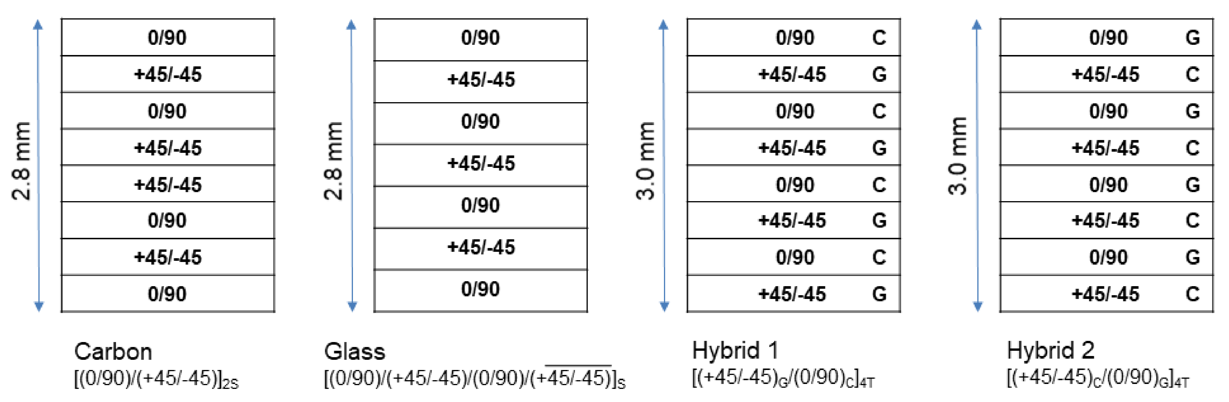
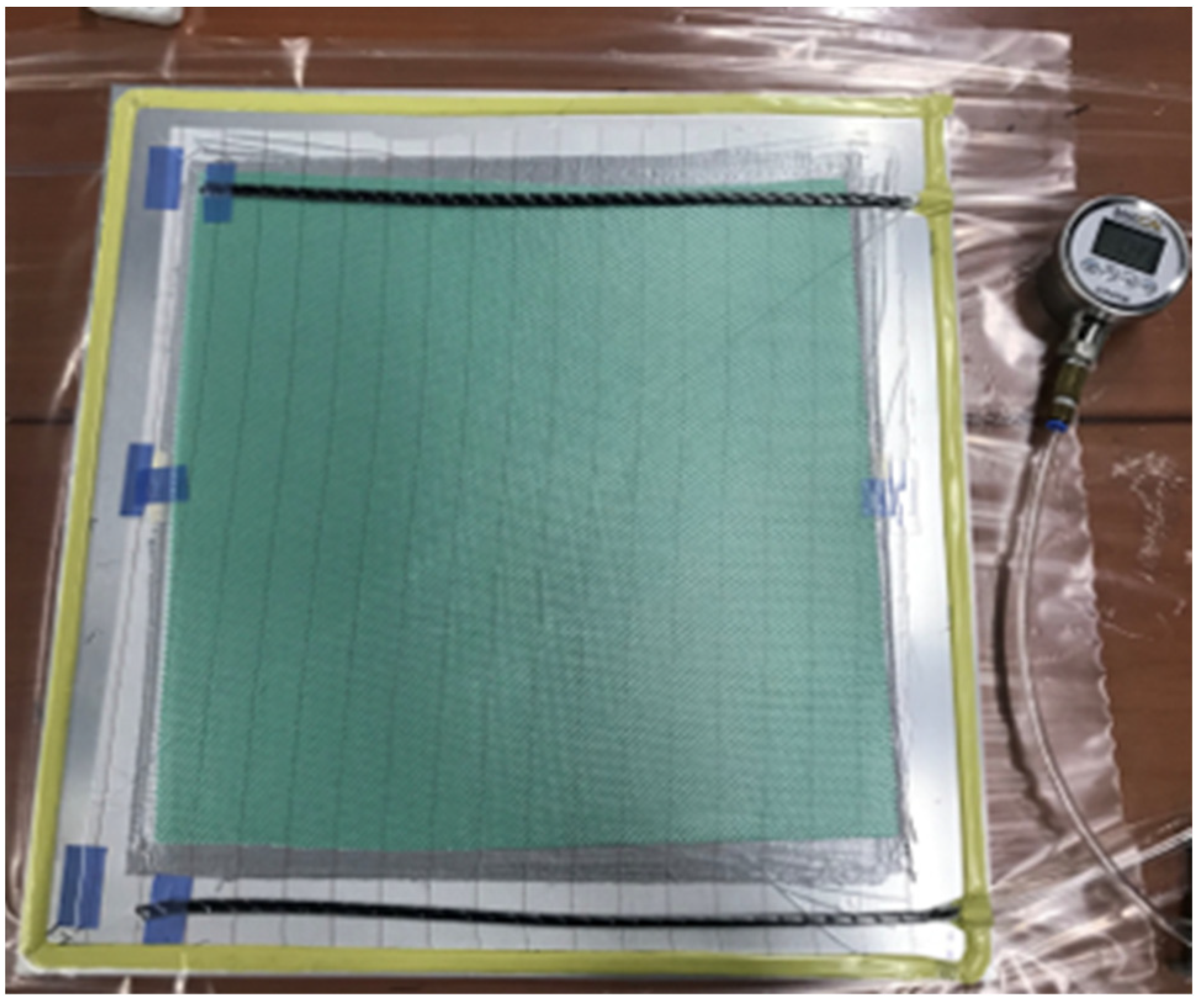
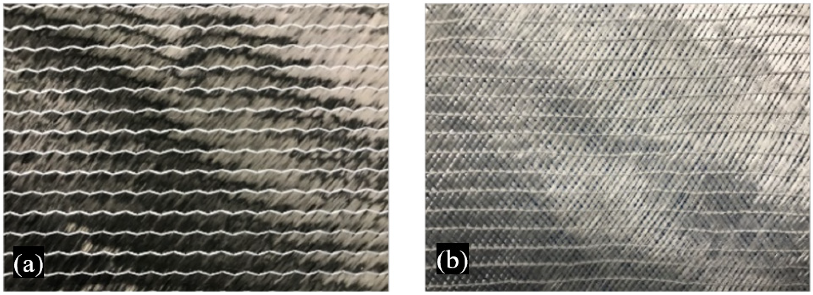
2.1. Manufacturing Process
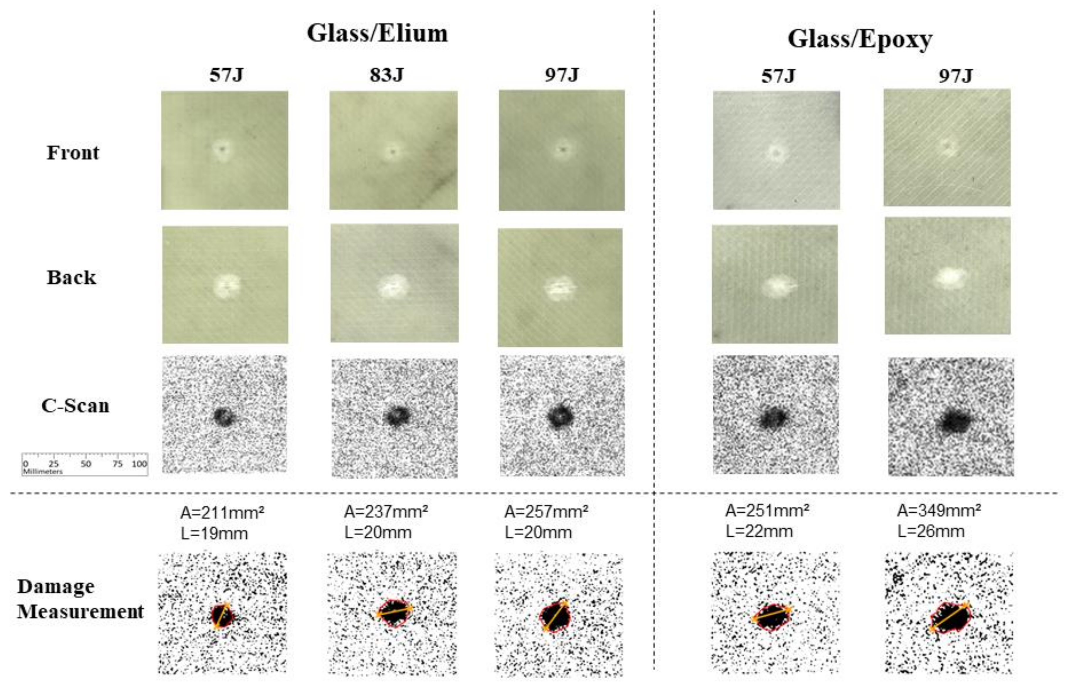
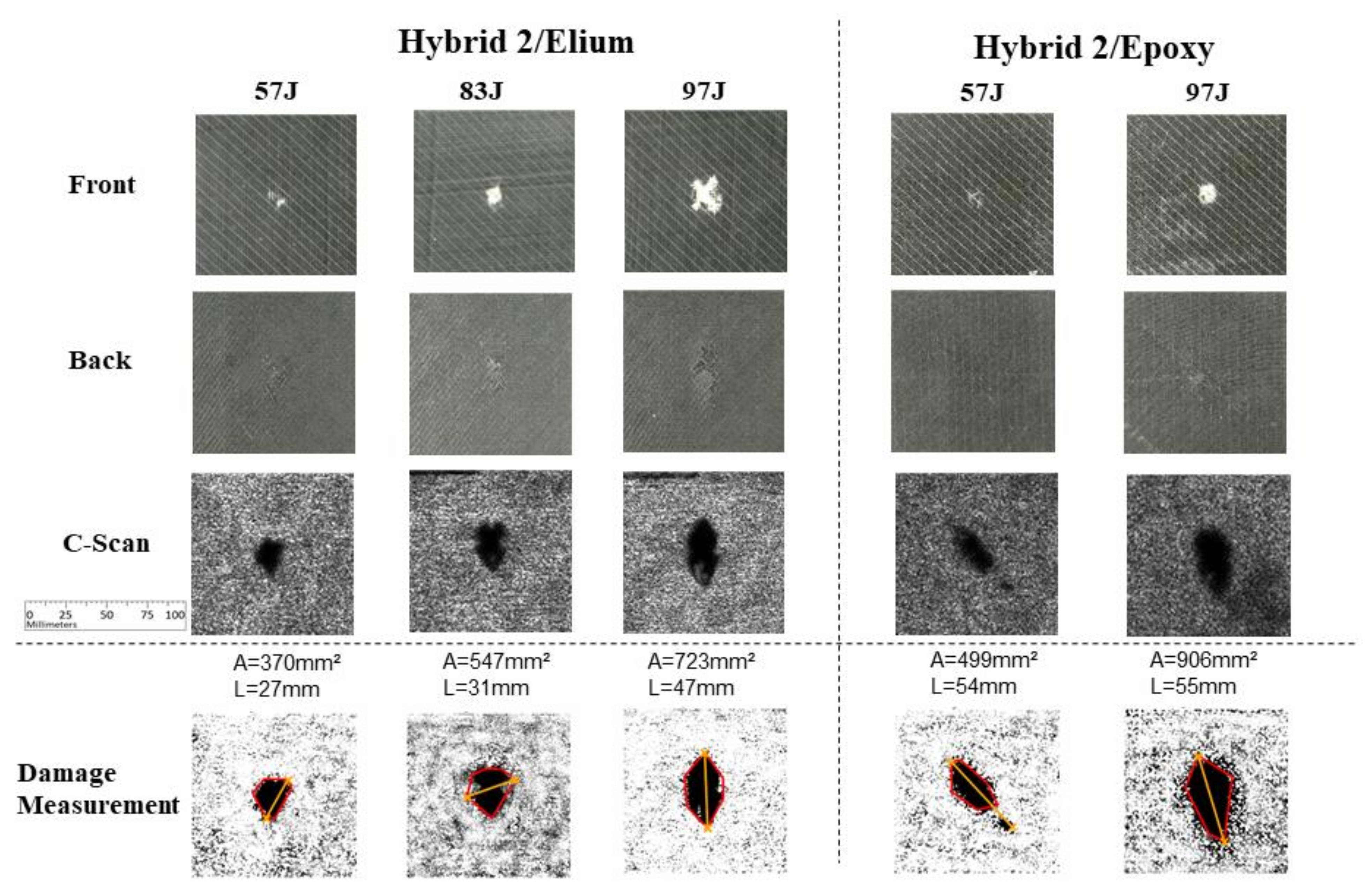
The thermoplastic resin ELIUM 188O (Arkema Co., Ltd., Colombes, France) was selected to be compared to a standard thermoset epoxy reference, EPR-L20 (Hexion Co., Ltd., Columbus, OH, USA). Both Elium (thermoplastic) and Epoxy (thermoset) resins were applied in conjunction with carbon, glass and hybrid layups to produce the impact test specimens. The selected NCF fabrics are shown in Figure 4.
The sample production process is illustrated in Figure 5. First, a dam is developed with sealant tape on an aluminum tool plate. The dry fabric is then arranged in the respective layup for each laminate case, followed by peel ply, flow media, and two spiral tubes used as resin source and drain. The pack is then covered by the bagging film. Vacuum is imposed to the system and maintained in order to assure leakage absence. Finally, the resin was injected using negative pressure suction. In the case of the thermoplastic resin Elium, the applied mixing ratio is ELIUM 188O 100 wt.% and curing agent BPO (Benzoyl Peroxide) 1.5 wt.%. For the Epoxy resin EPR-L20, the mixing ratio is L-20 100 wt.% and curing agent 33 wt.%. After resin injection, each laminate was cured at room temperature for 24 h. The Epoxy resin EPR-L20 was post-cured at 60 °C for another 15 h.
The specimens were cut to the equipment standard size (squares of 200 × 200 mm), using machining tools, and positioned in the impact test clamping apparatus, as shown in Figure 6.

2.2. C-Scan

A C-scan system (YASKAWA MOTOMAN Co. Ltd., Kitakyushu, Fukuoka, Japan, model CAUS-312) was used to verify the damage within the impacted specimens. Images were produced by ultrasonic wave transmission through water. The reflected wave phase and magnitude analysis allowed to visualize the state of the interfaces on the interior of the impacted specimens.

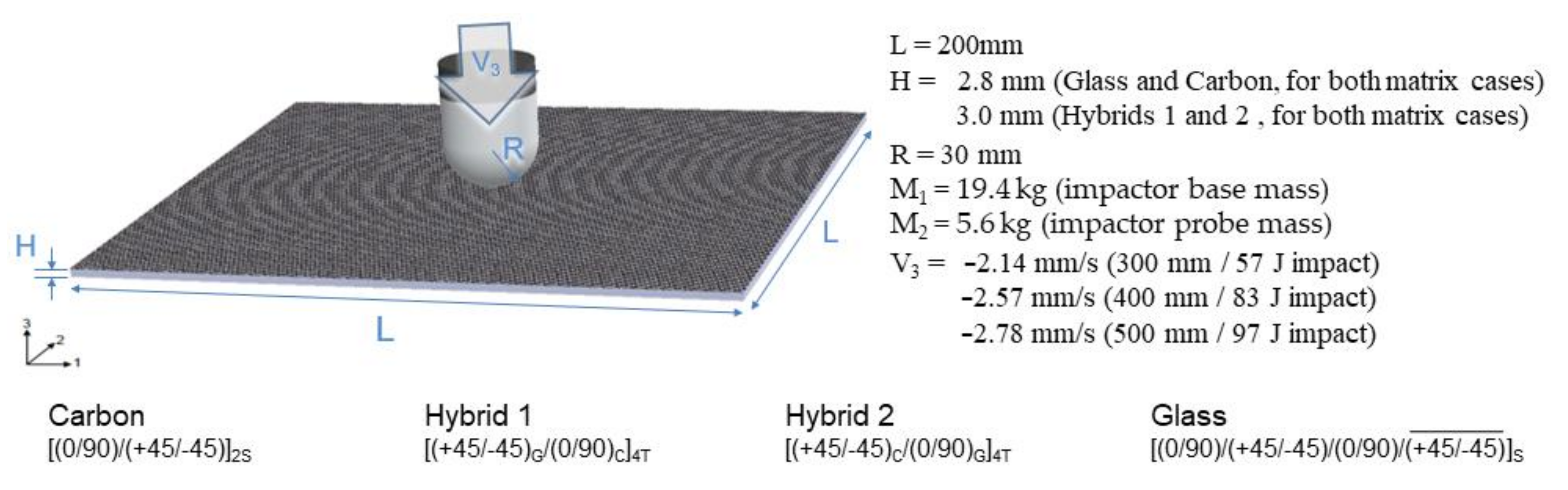
2.3. Numerical Finite Element Models

Auxiliary numerical simulations were developed to better understand the test physics and results, covering each drop weight impact test case. The commercial finite element software ABAQUS (v.6.14) explicit solution was selected as the dynamic model simulation platform. Eight different finite element models were developed, considering each material layup sequence for both Elium and Epoxy resins, as previously presented, totaling 30 experimentally studied configurations. The models were subjected to the same impact energy levels measured in the tests. Figure 7 presents the main parameters used in the model development. The initial impact energy input considers the initial velocity of the impactor, equal to the one measured in each case during the experimental tests. Support constraints were applied to the borders of each layer of the composite layups to simulate the clamping apparatus.
The impactor apparatus (25 kg total mass) may be described as a two degrees of freedom (2DOF) system, for both numerical simulation and experimental test data analysis. The system is represented by the dynamic system presented in Figure 8, dividing the total mass between the impactor base mass (M1 = 19.4 kg) and the impactor probe mass (M2 = 5.6 kg). Damping was disregarded, both for the load cell and plate, during the construction of the numerical models.
During the impact tests, forces were measures by a load cell (LC) placed between the two main parts, represented herein by the two masses in the model. In the proposed numerical models, the force measurements are possible to be obtained both at the load cell and at the impactor tip positions. Considering the impactor system as the proposed dynamic model, one can predict a force increment in the values actually applied to the plate if compared to the load cell measurements. Focusing on a direct finite element numerical simulation versus experimental data comparison, a 2DOF impactor model was developed using two masses attached by a contact surface, allowing to integrate forces at both load cell and impactor tip positions. The forces at the load cell position were used to compare numerical finite element results to experimental data in order to correctly simulate the measured load cell signal. Contact model was also applied between the impactor and plies, including self-contact between parts, in order to perform the impact explicit simulation. A parametric study was conducted to verify the estimated stiffness of 90% of steel Young’s modulus, adopted to the load cell model, demonstrating a small influence level (i.e., below method’s accuracy) on the results obtained using the measurement methods proposed in this work. Figure 9 shows normalized forces, integrated in both load cell and impactor tip model positions. Discrete values between 1% and 100% of steel Young’s modulus were considered as reference.
A fixed edge boundary condition was applied to the laminated plate finite element model borders (Figure 10a). Between each layer mesh (Figure 10b), a cohesive zone contact interface [56] was used to model the interfaces, covering the region around the impact point [green area in Figure 10c], to verify the influence of the delamination. Tie constraints were inserted in the remaining regions far from the impact point (gray area in Figure 10c) in order to reduce computational processing costs. The impactor was divided in an impactor base rigid model, and an also rigid impactor probe model (Figure 10d).
The mesh convergence study was developed using model meshes with totals of 19,650, 24,550, 29,694, 47,636, and 91,750 elements for the glass/thermoset case. A low velocity impact explicit case was simulated in each configuration, with sufficient energy to generate damage with no perforation, in order to verify the mesh influence in the results. The area measurement process applied in these studies is described in Section 2.4. During mesh convergence studies CZM (cohesive zone model) and Hashin failure criteria were analyzed separately aiming to better visualize each damage parameter. Figure 11 shows, for each proposed mesh configuration, three damaged area measurements: (i) an intra-laminar damage envelope, considering Hashin criteria only; (ii) an inter-laminar damage (delamination) envelope, considering cohesive criteria only; (iii) an intra-laminar and delamination superimposed damage envelope, considering both Hashin and cohesive damage results. For each defined mesh, the damaged area is calculated applying the three proposed envelope cases, and a mesh convergence parameter is defined comparing each damaged area value with its counterpart obtained using the following refined mesh. The computational time cost to process each case was computed using an Intel® Xeon® CPU E5-1607 (Santa Clara, CA, USA) v2 3.00 GHz machine with 16 GB of installed RAM. A mesh convergence criterion was defined considering the damaged area shapes separately and, based on the calculated areas, a 5% maximum measurement variation was assumed as the maximum accepted difference to next refined mesh. The 47636 elements mesh case was selected, considering the aforementioned criteria, as a tradeoff between computational costs and expected obtained results when applying the proposed mesh to the auxiliary numerical simulations.
Each full finite element model was created in ABAQUS based on the arrangements of unidirectional ply parts, each composed of 6728 nodes and 3249 SC8R linear hexahedral continuum shell elements [57], oriented and arranged according to the respective layup, where thickness was determined from the element nodal geometry and only the displacement degrees of freedom were taken into account. The impactor was modeled with two rigid bodies: the impactor base rigid model, composed by 202 nodes and 110 C3D8R linear hexahedral elements [57], and the impactor probe rigid model including the tip diameter, composed by 466 nodes and 2040 C3D4 linear tetrahedral elements [57]. Thus, the complete numerical models for carbon, hybrid1 and hibrid2 layups (16 plies), for both Elium and Epoxy matrices, were composed by a total of 108,314 nodes and 54,134 elements (51,984 SC8R linear hexahedral, 2040 C3D4 linear tetrahedral, and 110 C3D8R linear hexahedral elements). On the other hand, for glass/Elium and glass/Epoxy (layups with 14 plies), the models were composed by a total of 94,858 nodes and 47,636 elements (45,486 SC8R linear hexahedral, 2040 C3D4 linear tetrahedral, and 110 C3D8R linear hexahedral elements).

2.3.1. Materials

The auxiliary finite element models presented in this work were developed considering literature-based material properties, aiming to better understand the tests’ physics. Table 2 presents the material data for each NCF ply, including the literature data sources. This material data presented a good degree of numerical/experimental comparability when applied to the auxiliary models developed in this work, as well as in other studies in literature [58,59,60,61,62]. Despite that, it is worth emphasizing that detailed studies were not carried out here for numerical or experimental data validation, and more advanced models may be useful to improve numerical results.
An inter-laminar cohesive failure criterion [68] was applied using contact interfaces between each adjacent layer in order to simulate delamination during the impact procedure. Table 3 presents the interface material data, followed by literature data sources. For Hybrid 1 and Hybrid 2 specimens’ cases, the worst case between Elium and Epoxy options were implemented in the models. Stiffness coefficients in the normal and both shear directions, which relates the contact force to the penetration distance, were chosen automatically by ABAQUS/the explicit default contact enforcement method. The applied general contact algorithm uses a penalty method to enforce the contact constraints, such that the effect on the time increment is minimal yet the allowed mesh penetration is not significant in the analyses [57]. The applied interlaminar model (CZM) was assumed to be analogous to an adhesive model between each meso-scale lamina model, considering loading as purely in-plane, and delamination propagation mainly driven by shear in the homogeneous resin-rich region between plies.

2.3.2. Damage Criteria

Hashin damage initiation criterion [74] even with accuracy limitations, is widely applied in industrial application purposes [75] to predict the onset of damage for anisotropic fiber-reinforced materials and was selected for the auxiliary finite element simulations presented in this work. Damage can be initiated without a large amount of plastic deformations. Four distinct failure modes were considered [57]: tensile fiber failure ( σ 11 > 0 ), compressive fiber failure ( σ 11 < 0 ), tensile matrix failure ( σ 22 > 0 ), and compressive matrix failure ( σ 22 < 0 ). The undamaged material response is implemented using a linearly elastic model for simplicity, and the damage evolution law is based on the energy dissipated during the damage process and linear material softening [76].
Inter-laminar cohesive damage criteria [56] is also applied to the finite element model in order to simulate delamination and debonding damages between plies. Damage onset is implemented using the quadratic stress criterion, initiating damage when a quadratic interaction function, involving the contact stress ratios, reaches a value of one. The cohesive material response was developed based on the Benzeggagh–Kenane fracture criterion [57,77].

2.4. Area Measurement Process

A standard damage measurement procedure is proposed to verify the main damaged area in C-scan images, creating a damage outline, as proposed based by Tan et al. [78]. The maximum damage length was also measured to perform a quantitative reference of non-negligible cracks outside the main damage area. An image processing routine was implemented in Python, aiming to reduce the human influence on the presented measurements. In this procedure, the raw image was first imported and converted to a grayscale array. Otsu’s method [79] was applied to calculate an optimal threshold, maximizing the variance between two classes of pixels and minimizing the intra-class variance [80]. Using the obtained threshold as reference, the in-house semi-automatic tool tracks borderline polygons, filters the obtained data, and calculate its area, and the maximum damage length for each studied case. It is important to highlight that C-scan results, besides presenting a damage shape regularly close to the real specimen, are mostly overestimated [81,82]. This procedure makes it easier to visualize image variations observed in the C-scan, mostly already overestimated as mentioned before, leading the analysis to the safety side, but care must be taken not to over-reinforce the final structure.
The semi-automatic tool aims to achieve a fair judgement on the measurement process in experimental results, also being adapted to measure the main damage area in auxiliary finite element model graphical results. Focusing on obtaining comparable results to C-scan images, as proposed by Liu at al. [75], superimposed model images from each ply in the numerical results were used to perform a delamination envelope and an intra-laminar damage envelope. The image-to-binary process for Hashin and cohesive damage results are processed separately, and a Boolean operation is used to superimpose both images. Then the routine proceeds finding damage polygon and calculating its area.

3. Results

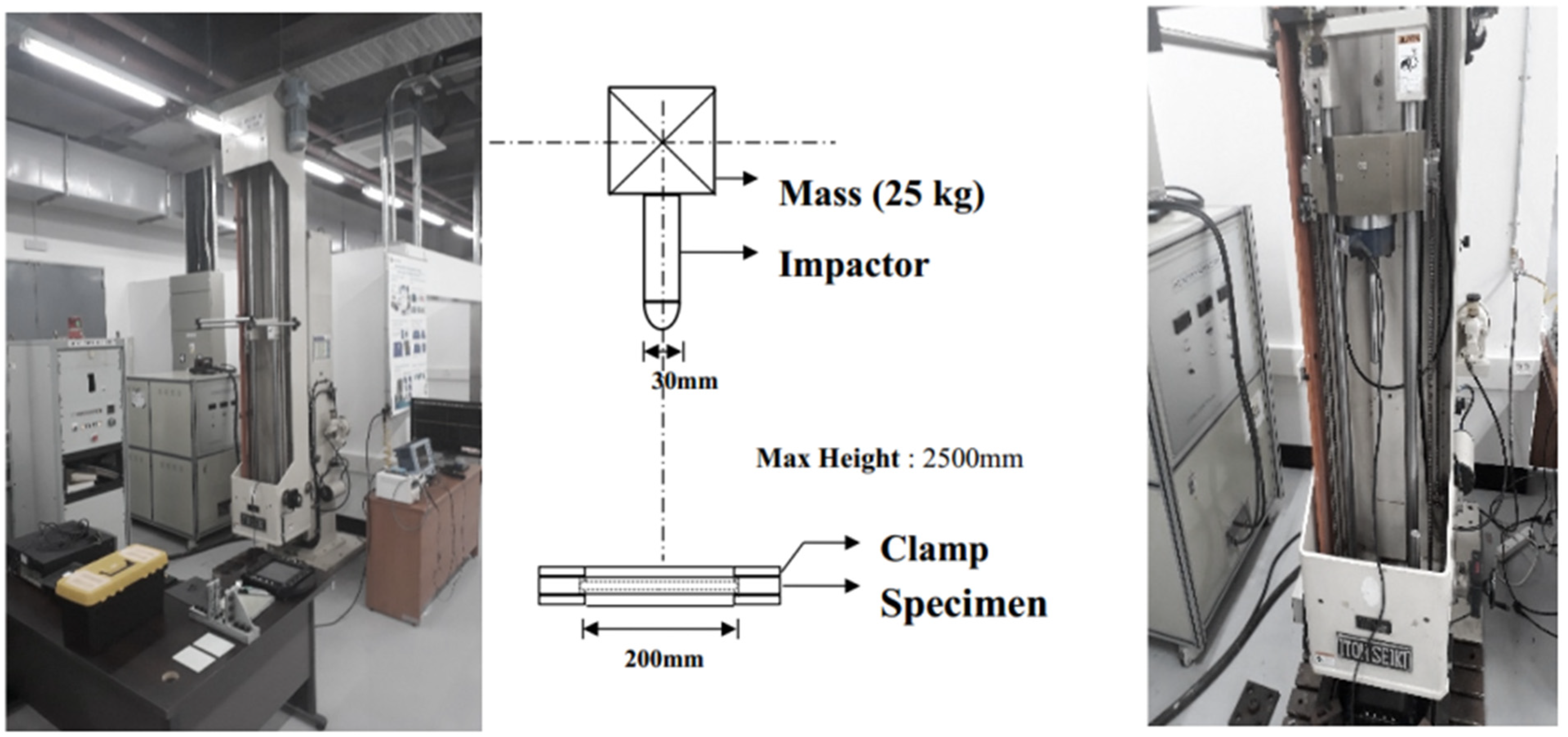
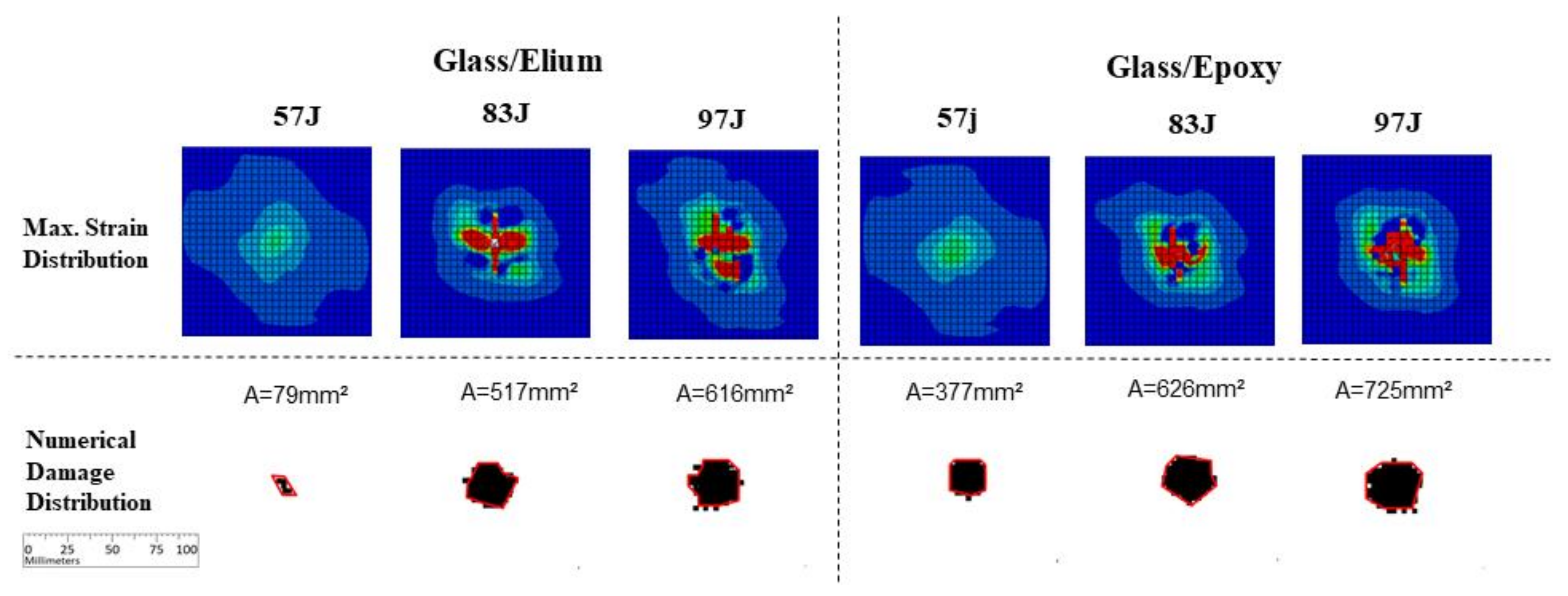
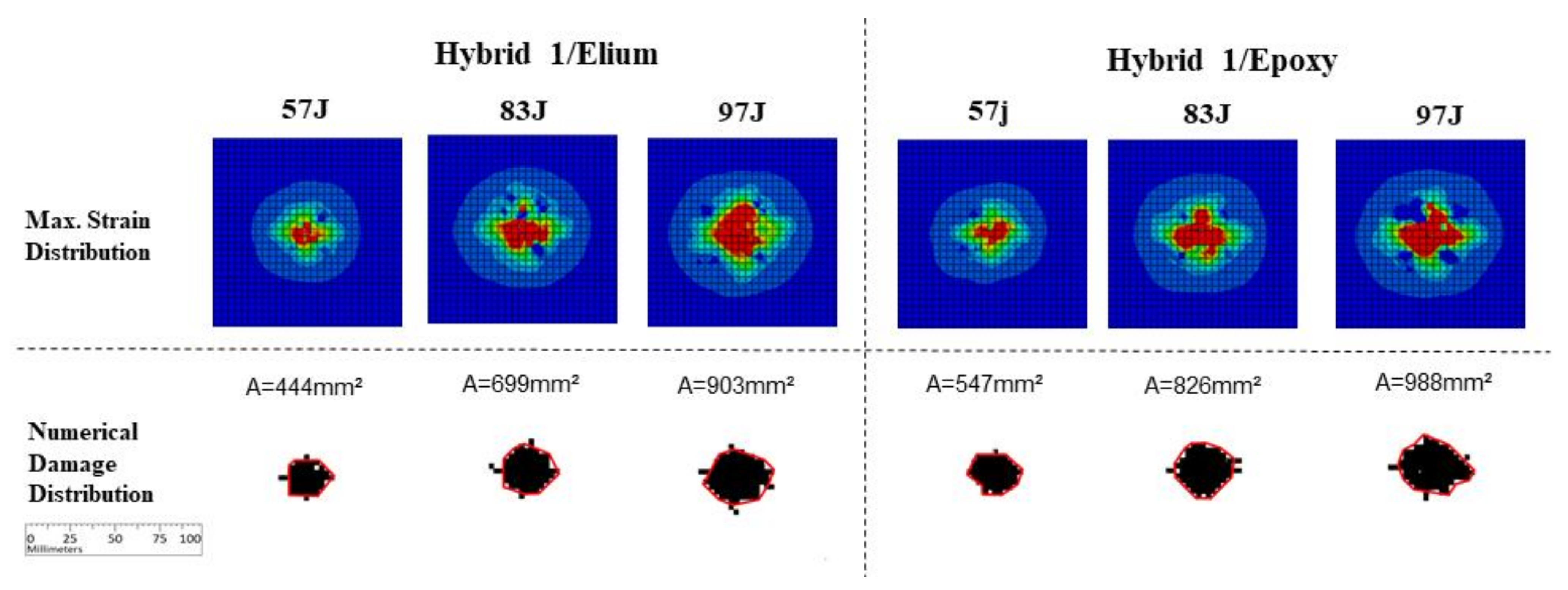
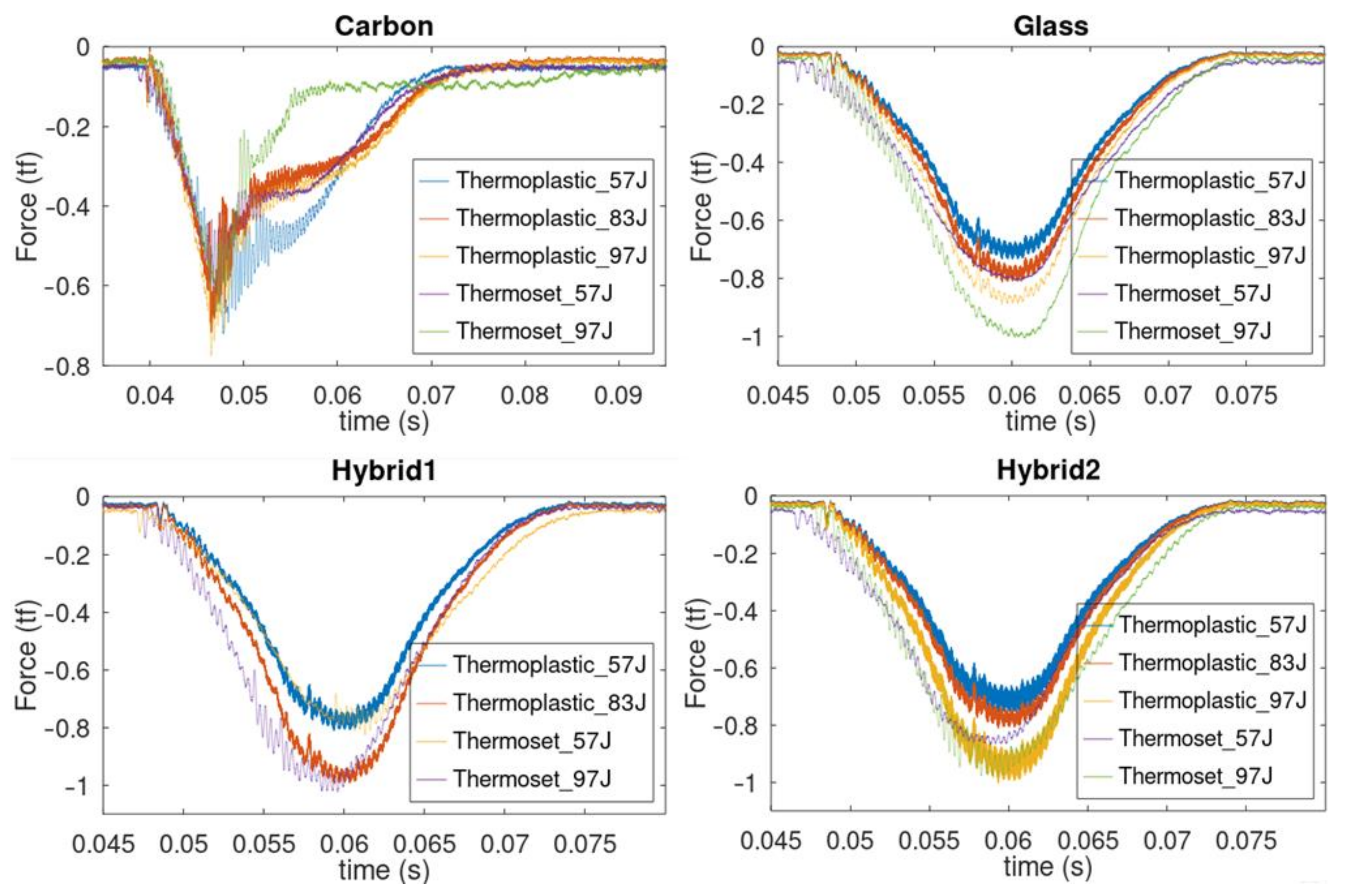
3.1. Experimental Studies

This section presents the obtained results in the proposed tests. Force measurements obtained during the experiments for each case are presented in Figure 12, as impact force vs. time plots for different energy levels and resin systems. It is possible to observe that these curves are not smooth for carbon fiber specimens due to penetration of the impactor in the panels. Additionally, it is possible to observe that penetration acts as a limitation of maximum measured impact forces in carbon specimens.
Figure 13 presents experimental results for carbon fiber with Elium and Epoxy resin systems. The columns depict the impact energy level for each resin system. The first two rows present front and back images from the impacted specimens, respectively. The obtained C-scan images are shown in the third, fourth and last row and contain images of the damage measurements, as previously explained. This presentation scheme is also used in the following figures for different fiber systems test results. In Figure 13 it is possible to observe a larger damage in Epoxy specimens as compared to Elium specimens, for both main damage and maximum length measurements. Considering the 97 J impact case, an almost complete perforation was observed for both matrices. Notice that due to the fragile failure characteristics of the carbon/Epoxy, very pronounced cracks may be seen if compared to its carbon/Elium counterparts. Comparing the measured areas for both matrices at each energy level, it is possible to observe a trend of increasing damage when conventional epoxy resin is applied: from 787 mm2 to 1136 mm2 for 57 J energy level, and from 1552 mm2 to 1624 mm2 for 97 J energy level. No impact tests were performed for epoxy specimens at 83 J for all the studied layups.
For the glass fiber cases, as presented in Figure 14, very small damage levels were observed for the tested energy levels, even though, as for carbon iber, larger damages are observed for Epoxy specimens when compared with Elium counterparts: an increment from 211 mm2 to 251 mm2 for 57 J energy level, and from 257 to 349 mm2 for 97 J energy level may be observed.
Figure 15 presents Hybrid 1 carbon/glass layup test results, where damage can be visually observed in the back images (second row), due to the contrast of the delaminated bottom glass layer. Again, it is possible to observe a damage level increment in the Epoxy specimens, comparing with Elium specimens: from 422 to 528 mm2 for 57 J energy level, and from 906 to 1012 mm2 for 97 J energy level. Considering the maximum length measurement parameter, a slight increment may be observed for 97 J (55 to 58 mm) and no increment was observed for 57 J case. Though no impact tests were performed for epoxy specimens at 83 J, it is possible to observe that the maximum length measurement parameter for Elium achieved the same value as the one obtained for Epoxy at 97 J.
The Hybrid 2 carbon/glass layup test results are presented in Figure 16. Similar to previous results, visual damages can be easily observed in the front images (first row) due to the contrast of the delaminated top glass layer. It is possible to verify the trend of larger damage levels, considering both measurement parameters, for Epoxy specimens comparing with Elium specimens: from 370 to 499 mm2 for 57 J energy level, and from 723 to 906 mm2 for 97 J energy level, and, considering the maximum length measurement parameter, an increment may be observed for 97 J (47 to 55 mm) and for 57 J (27 to 54 mm) cases.
As observed in the literature [6,7,32,33,37,83] regarding failure modes, Elium-based specimens, if compared to Epoxy-based counterparts, presents a less brittle failure (fracture) response due to the material plastic behavior. Additionally, it is important to observe that glass-fiber material based specimens are typically far less brittle than its carbon reinforced counterparts [84], which leads to the observed advantages in glass built specimens where, besides the carbon stiffness and strength intrinsic advantages. Hybridization, jointly with Elium thermoplastic resin application, is observed as a promising possibility to improve materials for advanced composite design.

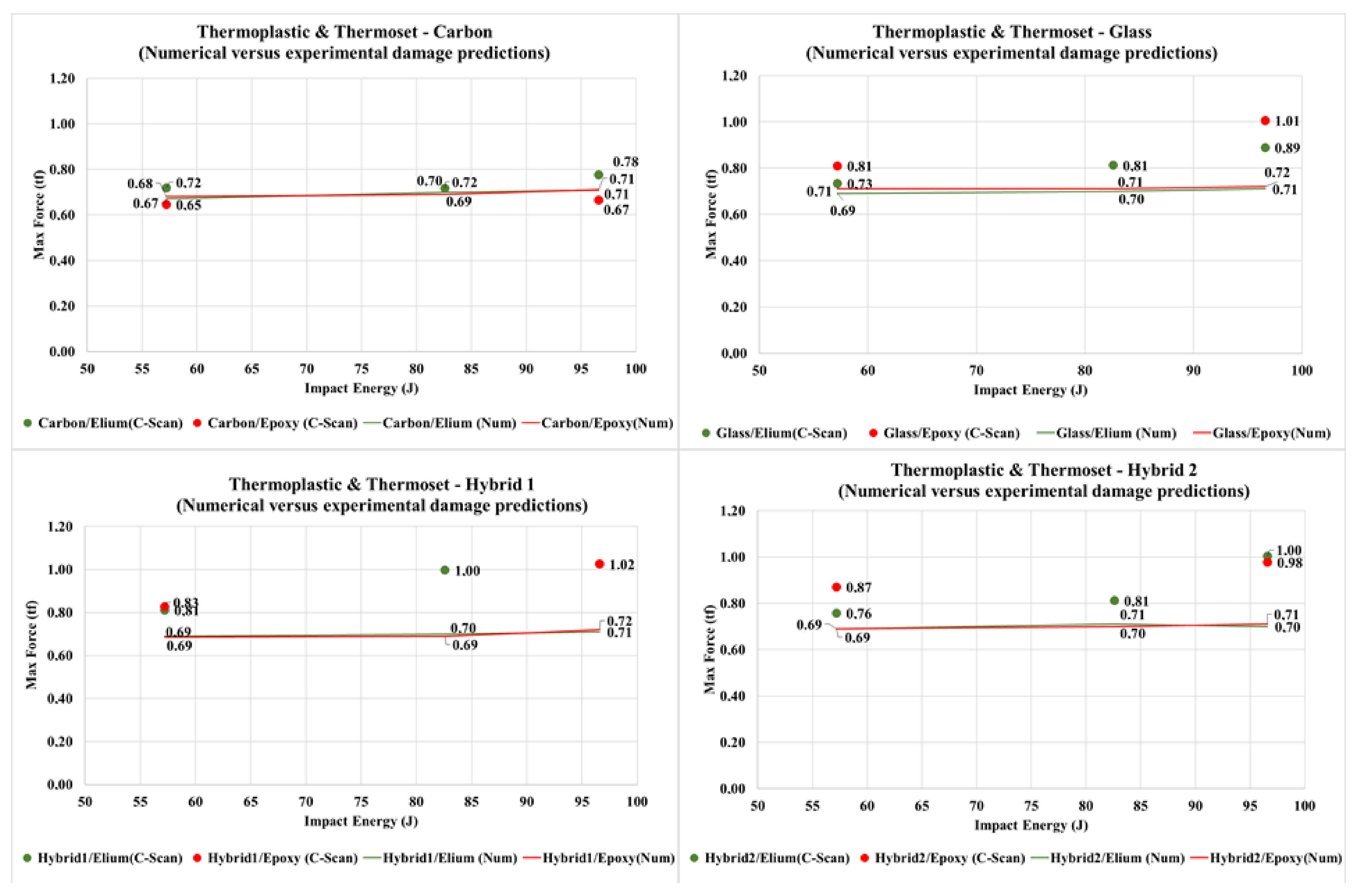
3.2. Numerical Studies
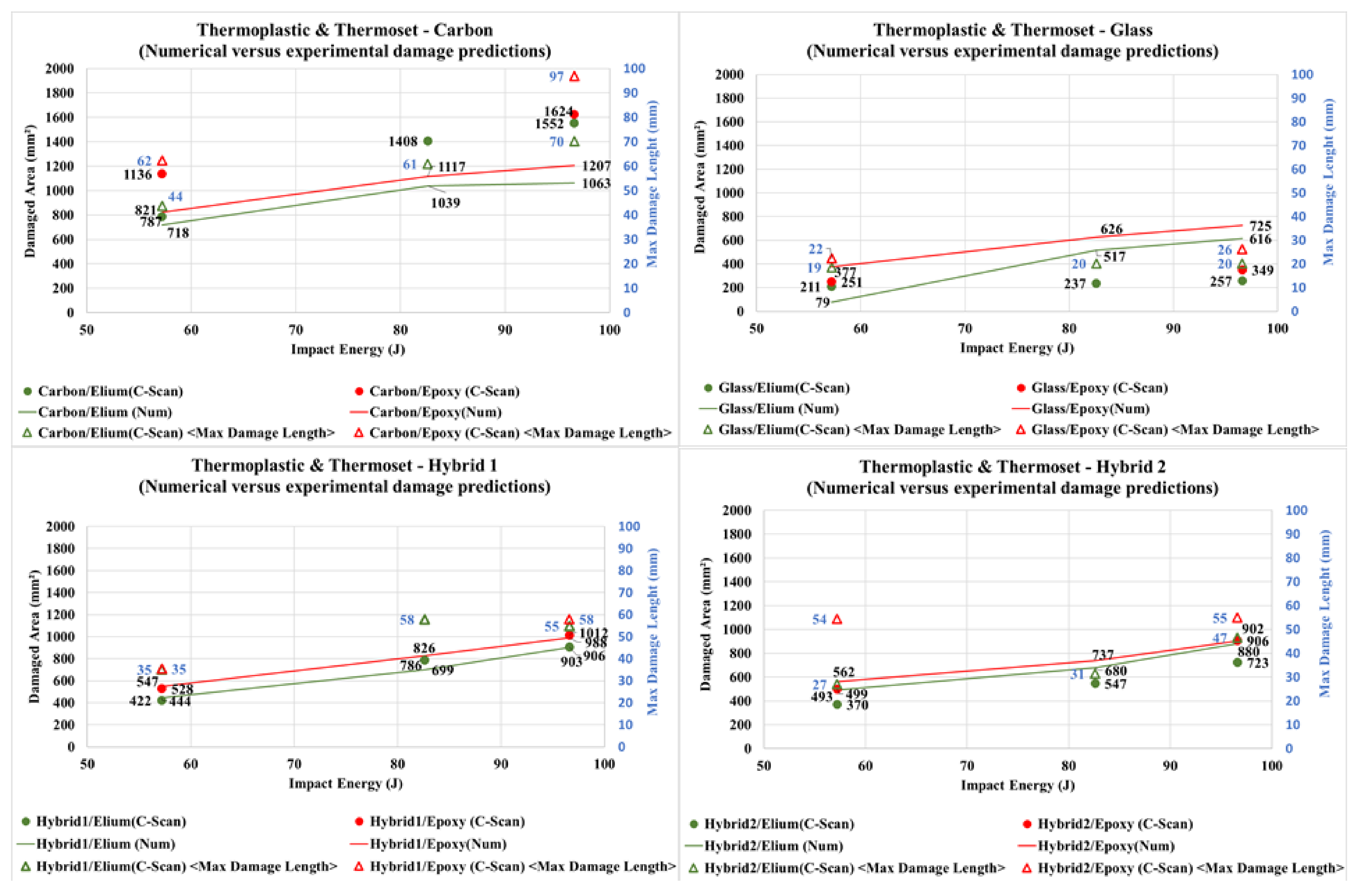
Based on finite element analyses simulations, Figure 17 presents results for carbon fiber specimens, observing a fairly good damage level correlation compared to experimental results (Figure 13), even though using a simplified numerical model. As in the figures for experimental results, the columns present different impact energy levels in simulations for each resin system. The first row presents a comparative strain distribution between results obtained for each studied case. To directly compare the damage levels to those obtained for C-scan results of tested panels, the second row presents the main damage area measured through the superimposed envelope considering both failure criteria, as previously described. These damage envelopes results were obtained considering superimposed results for each ply using the Hashin failure criterion [74] in a Boolean operation with superimposed results for each interface damage using the cohesive criterion [56]. This presentation scheme is followed in the sequent figures for simulation results of different fiber systems. One can observe in Figure 17, considering the top row, the presence of concentrated stresses outside the main impact region. In this region, in the lower row, it is possible to observe cracks in the specimens, also observed in the experimental results. It is possible to observe a damage level increment in the Epoxy specimens, comparing with Elium specimens: from 718 to 821 mm2 for 57 J energy level, from 1039 to 1117 mm2 for 83 J energy level, and from 1063 to 1207 mm2 for 97 J energy level.
Glass finite element simulation results are presented in Figure 18. It is possible to observe considerably larger damage levels in those numerical results, for both resins, when compared with those present in experimentally tested specimens (Figure 14). As well as that, it is possible to observe a damage level increment in the Epoxy specimens, comparing with Elium specimens: from 79 to 377 mm2 for 57 J energy level, from 517 to 626 mm2 for 83 J energy level, and from 616 to 725 mm2 for 97 J energy level. No significant cracks were noticed outside the main impact region, considering both strain distribution and damage envelope, agreeing to the experimental results.
Figure 19 presents finite element simulation results for the Hybrid 1 layup cases. A fairly good correlation can be verified of damage levels compared to experimental results (Figure 15), even though a simplified numerical model was used. It is also possible to observe a damage level increment in the Epoxy specimens, comparing with Elium counterparts: from 444 to 547 mm2 for 57 J energy level, from 699 to 826 mm2 for 83 J energy level, and from 903 to 988 mm2 for 97 J energy level. Small cracks were noticed outside the main impact region, considering both strain concentrations and damage envelope, agreeing to experimental results.
Results for finite element simulation for Hybrid 2 layup cases are presented in Figure 20. Again, it is possible to observe a reasonable numerical versus experimental correlation for damage levels considering experimental results (Figure 16). Again, it is also possible to observe a damage level increment in the Epoxy specimens, comparing with Elium counterparts: from 493 to 562 mm2 for 57 J energy level, from 680 to 737 mm2 for 83 J energy level, and from 880 to 902 mm2 for 97 J energy level. Small cracks were noticed outside the main impact region, considering both strain concentrations and damage envelope, agreeing to experimental results.

3.3. Analysis

Considering both the experimental and numerical results which Figure 21 presents, for each studied case, the largest load cell force measurement during the impact process. These results were considered as fairly adequate for the relatively simplified finite element deterministic models.
The damaged area and maximum damage length results are condensed Figure 22. Although carbon/Elium properties were approximated using carbon/Epoxy stress and strength data, finite element models present similar patterns to experimental data for both carbon and hybrid cases. Additionally, due to the model limitations, this simplified numerical approach may be non-conservative, as verified in some Hybrid 1 cases, serving only as a reference for studies. It is also possible to verify that carbon/Epoxy numerical results show smaller secondary intra-laminar damage (maximum length), in addition to the main measured damage, if compared to the carbon/Elium counterparts.
Considering the tested energy levels, for both Elium and Epoxy cases, small damages are observed for glass specimens in Figure 22. It is also possible to observe that the corresponding finite element results present a trend to simulate larger damage levels as compared with experimental results.
Also, according to Figure 22, small variation was observed between the test damage levels for carbon/Elium and carbon/Epoxy at 97 J impact energy level, considering the damaged area measurement procedure. However, the maximum damage length “secondary failures” are quite considerable for the carbon/Epoxy experimental case. Carbon/Epoxy’s relatively small main damage area may be explained by its fragile failure characteristics, since damage tends to be more localized, similarly to the expected result in a high energy ballistic test [18,70].
Hybrid/Elium panels show less impact damage than hybrid/Epoxy panels, again corroborating with the literature results [7,32,33,53,66,70] for thermoplastic versus thermoset resins with different reinforcement materials (Figure 22).

4. Discussion and Conclusions

An experimental impact test program was conducted in composite panels using a thermoplastic and thermoset resin systems reinforced by carbon, glass and hybrid car-bon/glass fibers layups. Only one impact test was performed for each configuration at each energy level.
As well as the similarities between Elium and a conventional thermoset matrix, in our results Elium (thermoplastic) panels presented less impact damage levels than Epoxy (thermoset) panels for the proposed layups (glass, carbon and hybrids). Overall, considering the results and the proposed measurement methodology, thermoplastic resin (Elium) layups, compared to its thermoset counterparts, presented reduction of damage areas for carbon, glass and hybrid fiber systems. Despite the lack of statistical representation, given that only one test was performed for each studied point, a trend of impact damage area reduction for Elium specimens was observed when considering all the studied cases. The studied Elium-based specimens presented in our studies a less brittle failure (fracture) response compared to Epoxy-based counterparts.
Glass-fiber material-based specimens presented, as typically expected, a far less brittle behavior if compared to its carbon reinforced counterparts. As well as carbon stiffness and strength intrinsic advantages, for both Elium (thermoplastic) and Epoxy (thermoset), glass showed the lowest damage levels while carbon showed the highest. It was observed that the presence of glass layers decreases the damaged area in both hybrid layup cases, since glass is more energy absorbent than carbon. The use of hybrid layups demonstrated to be a way to achieve a compromise solution between impact damage resistance and stress/strength characteristics in engineering applications. This should be added to the benefits of impact damage area reduction effect presented due to use of Elium thermoplastic resin.
Due to the inherent difficulties of a visual inspection of composite material, one may observe that a larger damaged area is verified considering the C-scan. On the other hand, it is important to highlight that C-scan tends to lead to overestimated results, besides presenting a damage shape regularly close to the real specimen’s damage. A measurement procedure was proposed herein to easier visualize damage variations in images. The tendency of obtaining overestimated results in C-scan exemplifies the difficulty of identifying composite material impact failures, even with the aid of specialized equipment.
Numerical models are commonly applied to assist and reduce testing costs. The auxiliary numerical models applied in this work, besides its simplicity, presented similar patterns if compared with experimental results, but caution needs to be taken since, as shown, some cases presented non-conservative results when comparing to experimental data. Even though it is possible to observe a considerable difference, which might be reduced using a higher fidelity finite element model for impact simulation, the relatively low fidelity models presented are useful to understand the physics and the results of the proposed problem.
Although carbon fiber composites are lighter and stronger, wind turbines blades are commonly built of glass fiber composites. Hybrid carbon/glass fiber composites became a feasible alternative to balance cost-performance for larger wind turbine blades. Applying Elium thermoplastic resin, jointly with hybridization, can be seen as a promising possibility to improve advanced composite materials design. Elium resin demonstrates to be competitive to replace traditional thermoset options, with advantages related to better reuse capabilities, ease of fabrication, and good impact and damage tolerance properties.

Author Contributions

Conceptualization, S.K.H., C.A.C.J. and T.H.L.P.; methodology, S.K.H., C.A.C.J. and T.H.L.P.; software, T.H.L.P. and L.A.G.T.; validation, T.H.L.P., C.A.C.J. and S.K.H.; formal analysis, T.H.L.P., C.A.C.J. and S.K.H.; investigation, T.H.L.P., W.G., L.A.G.T., C.A.C.J. and S.K.H.; resources, S.K.H., and C.A.C.J.; data curation, T.H.L.P., C.A.C.J. and S.K.H.; writing—original draft preparation, T.H.L.P.; writing—review and editing, C.A.C.J., S.K.H., L.A.G.T., W.G. and T.H.L.P.; visualization, T.H.L.P., W.G., L.A.G.T., C.A.C.J. and S.K.H.; supervision, S.K.H. and C.A.C.J.; project administration, S.K.H. and C.A.C.J.; funding acquisition, S.K.H. and C.A.C.J. All authors have read and agreed to the published version of the manuscript.

Funding

This work was supported by CAPES, CNPq, and FAPEMIG. The first author is a CAPES scholar from Doctoral Sandwich Abroad Program (in portuguese: Programa de Doutorado Sanduíche no Exterior-PDSE), edital no. 47/2017, process number 88881.187859/2018-01.

Institutional Review Board Statement

Not applicable.

Informed Consent Statement

Not applicable.

Data Availability Statement

Data is available upon request from the corresponding author.

Acknowledgments

The authors are thankful for the assistance of the Structural Engineering Department of UFMG, the Department of Mechanical Engineering of Hanyang University, and to Pierre Gerárd and Arkema Group. This work was also supported by Brain Korea 4.

Conflicts of Interest

The authors declare no conflict of interest. The funders had no role in the design of the study; in the collection, analyses, or interpretation of data; in the writing of the manuscript, or in the decision to publish the results.

References

  1. Fthenakis, V.; Kim, H.C. Land use and electricity generation: A life-cycle analysis. Renew. Sustain. Energy Rev. 2009, 13, 1465–1474. [Google Scholar] [CrossRef] [Green Version]
  2. Eker, B.; Akdogan, A.; Vardar, A. Using of Composite Material in Wind Turbine Blades. J. Appl. Sci. 2006, 6, 2917–2921. [Google Scholar] [CrossRef] [Green Version]
  3. Mishnaevsky, L.; Branner, K.; Petersen, H.N.; Beauson, J.; McGugan, M.; Sørensen, B.F. Materials for wind turbine blades: An overview. Materials 2017, 10, 1285. [Google Scholar] [CrossRef] [PubMed] [Green Version]
  4. Sørensen, B.F.; Jørgensen, E.; Debel, C.P.; Jensen, F.M.; Jensen, H.M.; Jacobsen, T.K.; Halling, K.M. Improved Design of Large Wind Turbine Blade of Fiber Composites Based on Studies of Scale Effects (Phase 1); U.S. Department of Energy: Washington, DC, USA, 2004; Volume 1390, ISBN 87-550-3176-5.
  5. Aymerich, F. Composite Materials for Wind Turbine Blades: Issues and Challenges; Department of Mechanical, Chemical and Materials Engineering University of Cagliari: Cagliari, Italy, 2012; pp. 29–32. [Google Scholar]
  6. Subramani, N.; Murali, J.G.; Suresh, P.; Sankar, V.V.A. Review on Hybrid Composite Materials and its Applications. Int. Res. J. Eng. Technol. 2017, 4, 1921–1925. [Google Scholar]
  7. Kinvi-Dossou, G.; Matadi Boumbimba, R.; Bonfoh, N.; Garzon-Hernandez, S.; Garcia-Gonzalez, D.; Gerard, P.; Arias, A. Innovative acrylic thermoplastic composites versus conventional composites: Improving the impact performances. Compos. Struct. 2019, 217, 1–13. [Google Scholar] [CrossRef]
  8. Liu, H.; Liu, J.; Ding, Y.; Hall, Z.E.; Kong, X.; Zhou, J.; Blackman, B.R.K.; Kinloch, A.J.; Dear, J.P. A three-dimensional elastic-plastic damage model for predicting the impact behaviour of fibre-reinforced polymer-matrix composites. Compos. Part B Eng. 2020, 201, 108389. [Google Scholar] [CrossRef]
  9. Kehrer, L.; Wood, J.T.; Böhlke, T. Mean-field homogenization of thermoelastic material properties of a long fiber-reinforced thermoset and experimental investigation. J. Compos. Mater. 2020, 54, 3777–3799. [Google Scholar] [CrossRef]
  10. Verma, A.S.; Vedvik, N.P.; Gao, Z. Numerical assessment of wind turbine blade damage due to contact/impact with tower during installation. In Proceedings of the IOP Conference Series: Materials Science and Engineering, Busan, Korea, 25–27 August 2017; Volume 276. [Google Scholar]
  11. Verma, A.S.; Jiang, Z.; Vedvik, N.P.; Gao, Z.; Ren, Z. Impact assessment of a wind turbine blade root during an offshore mating process. Eng. Struct. 2019, 180, 205–222. [Google Scholar] [CrossRef]
  12. Verma, A.S.; Vedvik, N.P.; Gao, Z. A comprehensive numerical investigation of the impact behaviour of an offshore wind turbine blade due to impact loads during installation. Ocean Eng. 2019, 172, 127–145. [Google Scholar] [CrossRef] [Green Version]
  13. Verma, A.S.; Vedvik, N.P.; Haselbach, P.U.; Gao, Z.; Jiang, Z. Comparison of numerical modelling techniques for impact investigation on a wind turbine blade. Compos. Struct. 2019, 209, 856–878. [Google Scholar] [CrossRef]
  14. Keegan, M.H.; Nash, D.; Stack, M. Numerical modelling of hailstone impact on the leading edge of a wind turbine blade. In Proceedings of the EWEA (European Wind Energy Association) Annual Wind Energy Event 2013, Vienna, Austria, 4–7 February 2013. [Google Scholar]
  15. Ullah, H.; Silberschmidt, V.V. Analysis of impact induced damage in composites for wind turbine blades. In Proceedings of the 2015 Power Generation System and Renewable Energy Technologies (PGSRET), Islamabad, Pakistan, 10–11 June 2015. [Google Scholar] [CrossRef] [Green Version]
  16. Fotouhi, M.; Damghani, M.; Leong, M.C.; Fotouhi, S.; Jalalvand, M.; Wisnom, M.R. A comparative study on glass and carbon fibre reinforced laminated composites in scaled quasi-static indentation tests. Compos. Struct. 2020, 245, 112327. [Google Scholar] [CrossRef]
  17. Liu, Y.J.; Jiang, Z.; Wen, H.M. Predicting impact induced delamination of FRP laminates. Int. J. Impact Eng. 2020, 137, 103436. [Google Scholar] [CrossRef]
  18. Zhang, C.; Zhu, Q.; Curiel-Sosa, J.L.; Bui, T.Q. Ballistic performance and damage simulation of fiber metal laminates under high-velocity oblique impact. Int. J. Damage Mech. 2020, 29, 1011–1034. [Google Scholar] [CrossRef]
  19. Meon, M.S.; Nor, N.H.M.; Shawal, S.; Saedon, J.B.; Rao, M.N.; Schröder, K.-U. On the Modelling Aspect of Low- Velocity Impact Composite Laminates. J. Mech. Eng. 2020, 17, 13–25. [Google Scholar]
  20. Larsen, K. Recycling wind turbine blades. Renew. Energy Focus 2009, 9, 70–73. [Google Scholar] [CrossRef]
  21. Murray, R.E.; Beach, R.; Barnes, D.; Snowberg, D.; Berry, D.; Rooney, S.; Jenks, M.; Gage, B.; Boro, T.; Wallen, S.; et al. Structural validation of a thermoplastic composite wind turbine blade with comparison to a thermoset composite blade. Renew. Energy 2021, 164, 1100–1107. [Google Scholar] [CrossRef]
  22. Thomas, L.; Ramachandra, M. Advanced materials for wind turbine blade—A Review. Mater. Today Proc. 2018, 5, 2635–2640. [Google Scholar] [CrossRef]
  23. Forcier, L.-C.; Joncas, S. Development of a structural optimization strategy for the design of next generation large thermoplastic wind turbine blades. Struct. Multidiscip. Optim. 2012, 45, 889–906. [Google Scholar] [CrossRef]
  24. Murray, R.E.; Jenne, S.; Snowberg, D.; Berry, D.; Cousins, D. Techno-economic analysis of a megawatt-scale thermoplastic resin wind turbine blade. Renew. Energy 2019, 131, 111–119. [Google Scholar] [CrossRef]
  25. Fonte, R.; Xydis, G. Wind turbine blade recycling: An evaluation of the European market potential for recycled composite materials. J. Environ. Manag. 2021, 287, 112269. [Google Scholar] [CrossRef] [PubMed]
  26. Jensen, J.P. Evaluating the environmental impacts of recycling wind turbines. Wind Energy 2019, 22, 316–326. [Google Scholar] [CrossRef]
  27. Jensen, J.P.; Skelton, K. Wind turbine blade recycling: Experiences, challenges and possibilities in a circular economy. Renew. Sustain. Energy Rev. 2018, 97, 165–176. [Google Scholar] [CrossRef]
  28. Fox, T.R. Recycling Wind Turbine Blade Composite Material as Aggregate in Concrete. Master’s Thesis, Iowa State University, Ames, IA, USA, 2016; p. 57. [Google Scholar]
  29. Andersen, P.D.; Bonou, A.; Beauson, J.; Brønsted, P. Recycling of wind turbines. In DTU International Energy Report 2014: Wind Energy—Drivers and Barriers for Higher Shares of Wind in the Global Power Generation Mix; Larsen, H.H., Petersen, L.S., Eds.; DTU: Kongens Lyngby, Denmark, 2014. [Google Scholar]
  30. Åkesson, D.; Foltynowicz, Z.; Christéen, J.; Skrifvars, M. Microwave pyrolysis as a method of recycling glass fibre from used blades of wind turbines. J. Reinf. Plast. Compos. 2012, 31, 1136–1142. [Google Scholar] [CrossRef]
  31. Mamanpush, S.H.; Li, H.; Englund, K.; Tabatabaei, A.T. Recycled wind turbine blades as a feedstock for second generation composites. Waste Manag. 2018, 76, 708–714. [Google Scholar] [CrossRef] [PubMed]
  32. Kazemi, M.E.; Shanmugam, L.; Lu, D.; Wang, X.; Wang, B.; Yang, J. Mechanical properties and failure modes of hybrid fiber reinforced polymer composites with a novel liquid thermoplastic resin, Elium®. Compos. Part A Appl. Sci. Manuf. 2019, 125, 105523. [Google Scholar] [CrossRef]
  33. Bhudolia, S.K.; Joshi, S.C. Low-velocity impact response of carbon fibre composites with novel liquid Methylmethacrylate thermoplastic matrix. Compos. Struct. 2018, 203, 696–708. [Google Scholar] [CrossRef]
  34. Al-Hajaj, Z.; Sy, B.L.; Bougherara, H.; Zdero, R. Impact properties of a new hybrid composite material made from woven carbon fibres plus flax fibres in an epoxy matrix. Compos. Struct. 2019, 208, 346–356. [Google Scholar] [CrossRef]
  35. Bunea, M.; Cîrciumaru, A.; Buciumeanu, M.; Bîrsan, I.G.; Silva, F.S. Low velocity impact response of fabric reinforced hybrid composites with stratified filled epoxy matrix. Compos. Sci. Technol. 2019, 169, 242–248. [Google Scholar] [CrossRef]
  36. Guida, M.; Sellitto, A.; Marulo, F.; Riccio, A. Analysis of the impact dynamics of shape memory alloy hybrid composites for advanced applications. Materials 2019, 12, 153. [Google Scholar] [CrossRef] [Green Version]
  37. Obande, W.; Ray, D.; Brádaigh, C.M.Ó. Viscoelastic and drop-weight impact properties of an acrylic-matrix composite and a conventional thermoset composite—A comparative study. Mater. Lett. 2019, 238, 38–41. [Google Scholar] [CrossRef]
  38. Bhudolia, S.K.; Joshi, S.C.; Bert, A.; Yi Di, B.; Makam, R.; Gohel, G. Flexural characteristics of novel carbon methylmethacrylate composites. Compos. Commun. 2019, 13, 129–133. [Google Scholar] [CrossRef]
  39. Cousins, D.S. Advanced Thermoplastic Composites for Wind Turbine Blade Manufacturing; Colorado School of Mines: St. Golden, CO, USA, 2018. [Google Scholar]
  40. Murray, R.E.; Swan, D.; Snowberg, D.; Berry, D.; Beach, R.; Rooney, S. Manufacturing a 9-meter thermoplastic composite wind turbine blade. In Proceedings of the 32nd Technical Conference of the American Society for Composites 2017, West Lafayette, IN, USA, 23–25 October 2017; Volume 1, pp. 29–43. [Google Scholar] [CrossRef] [Green Version]
  41. Teuwen, J.J.E. Thermoplastic Composite Wind Turbine Blades: Kinetics and Processability; TU Delft University: Delft, The Netherlands, 2011. [Google Scholar]
  42. Vallons, K.; Adolphs, G.; Lucas, P.; Lomov, S.V.; Verpoest, I. Quasi-UD glass fibre NCF composites for wind energy applications: A review of requirements and existing fatigue data for blade materials. Mech. Ind. 2013, 14, 175–189. [Google Scholar] [CrossRef]
  43. Mohamed, M.H.; Wetzel, K.K. 3D woven carbon/glass hybrid spar cap for wind turbine rotor blade. J. Sol. Energy Eng. Trans. ASME 2006, 128, 562–573. [Google Scholar] [CrossRef]
  44. Ong, C.; Tsai, S.W. The Use of Carbon Fibers in Wind Turbine Blade Design: A SERI-8 Blade Example; SAND2000-0478; U.S. Department of Energy: Washington, DC, USA, 2000. [Google Scholar]
  45. Papa, I.; Ricciardi, M.R.; Calzolari, A.; Langella, A.; Tirillò, J.; Sarasini, F.; Lopresto, V. Mechanical behavior and damage degree of hybrid glass/carbon composites at low temperature. Polym. Compos. 2021, 42, 2432–2444. [Google Scholar] [CrossRef]
  46. Pérez-Martín, M.J.; Enfedaque, A.; Dickson, W.; Gálvez, F. Impact behavior of hybrid glass/carbon epoxy composites. J. Appl. Mech. Trans. ASME 2013, 80, 1–7. [Google Scholar] [CrossRef]
  47. Sutcliffe, M.P.F.; Monroy Aceves, C.; Stronge, W.J.; Choudhry, R.S.; Scott, A.E. Moderate speed impact damage to 2D-braided glass-carbon composites. Compos. Struct. 2012, 94, 1781–1792. [Google Scholar] [CrossRef] [Green Version]
  48. Kistaiah, N.; Udaya Kiran, C.; Ramachandra Reddy, G.; Sreenivasa Rao, M. Mechanical characterization of hybrid composites: A review. J. Reinf. Plast. Compos. 2014, 33, 1364–1372. [Google Scholar] [CrossRef]
  49. Nguyen, H.; Zatar, W.; Mutsuyoshi, H. Hybrid Polymer Composites for Structural Applications; Elsevier Ltd.: Amsterdam, The Netherlands, 2017; ISBN 9780081007860. [Google Scholar]
  50. Banerjee, S.; Sankar, B. V Mechanical properties of hybrid composites using finite element method based micromechanics. Compos. Part B Eng. 2014, 58, 318–327. [Google Scholar] [CrossRef]
  51. Vallons, K.; Duque, I.; Lomov, S.V.; Verpoest, I. Fibre orientation effects on the tensile properties of biaxial carbon/epoxy NCF composites. In Proceedings of the ICCM International Conference on Composite Materials, Melbourne, Australia, 11–16 August 2009. [Google Scholar]
  52. Lomov, S.V.; Ivanov, D.S.; Vallons, K.; Verpoest, I.; Klimshin, D.V.; Truong, T.C. Peculiarities of damage behaviour of NCF carbon/epoxy laminates under tension. In Proceedings of the ICCM International Conference on Composite Materials, Kyoto, Japan, 8–13 July 2007. [Google Scholar]
  53. Kinvi-Dossou, G.; Bonfoh, N.; Matadi Boumbimba, R.; Koutsawa, Y.; Lachaud, F.; Nyoungue, A.; Gerard, P. A mesoscale modelling approach of glass fibre/Elium acrylic woven laminates for low velocity impact simulation. Compos. Struct. 2020, 252, 112671. [Google Scholar] [CrossRef]
  54. Edgren, F. Compressive failure of NCF composites. In Proceedings of the 20th Technical Conference of the American Society for Composites 2005, Philadelphia, PA, USA, 7–9 September 2005; Volume 3, ISBN 9781622762828. [Google Scholar]
  55. ASTM. D7136: Standard test method for measuring the damage resistance of a fiber-renforced polymer matrix composite to a drop-weight impact. In Annual Book of ASTM Standards; ASTM International: West Conshocken, PA, USA, 2014; pp. 1–16. [Google Scholar] [CrossRef]
  56. Camanho, P.; Davila, C.G. Mixed-Mode Decohesion Finite Elements in for the Simulation Composite of Delamination Materials; NASA: Washington, DC, USA, 2002. [CrossRef]
  57. Simulia. ABAQUS (2014) CAE User’s Manual, Version 6.14; Simulia: Johnston, RI, USA, 2014. [Google Scholar]
  58. Koloor, S.S.R.; Karimzadeh, A.; Yidris, N.; Petrů, M.; Ayatollahi, M.R.; Tamin, M.N. An energy-based concept for yielding of multidirectional FRP composite structures using a mesoscale lamina damage model. Polymers 2020, 12, 157. [Google Scholar] [CrossRef] [PubMed] [Green Version]
  59. Koloor, S.S.R.; Ayatollahi, M.R.; Tamin, M.N. Elastic-damage deformation response of fiber-reinforced polymer composite laminates with lamina interfaces. J. Reinf. Plast. Compos. 2017, 36, 832–849. [Google Scholar] [CrossRef]
  60. Koloor, S.S.; Khosravani, M.R.; Hamzah, R.I.R.; Tamin, M.N. FE model-based construction and progressive damage processes of FRP composite laminates with different manufacturing processes. Int. J. Mech. Sci. 2018, 141, 223–235. [Google Scholar] [CrossRef]
  61. Nakatani, H.; Kosaka, T.; Osaka, K.; Sawada, Y. Damage characterization of titanium/GFRP hybrid laminates subjected to low-velocity impact. Compos. Part A Appl. Sci. Manuf. 2011, 42, 772–781. [Google Scholar] [CrossRef]
  62. Shi, Y.; Swait, T.; Soutis, C. Modelling damage evolution in composite laminates subjected to low velocity impact. Compos. Struct. 2012, 94, 2902–2913. [Google Scholar] [CrossRef]
  63. Toray Carbon Fiber Toray T700 Technical Data Sheet. Available online: https://www.toraycma.com/page.php?id=661 (accessed on 2 February 2021).
  64. Arkema Elium Liquid Thermoplastics Technical Data Sheet. Available online: https://www.arkema.com/global/en/products/product-finder/product-range/incubator/elium_resins/ (accessed on 8 August 2020).
  65. Daniel, I.M.; Ishai, O. Engineering Mechanics of Composite Materials; Oxford University Press: Oxford, UK, 2006; ISBN 9780195150971. [Google Scholar]
  66. Lorriot, T.; El Yagoubi, J.; Fourel, J.; Tison, F. Non-conventional Glass fiber NCF composites with thermoset and thermoplastic matrices. In Proceedings of the International Conference on Composite Materials (ICCM 2015), Copenhagen, Danemark, 19–24 July 2015. [Google Scholar]
  67. Fadhil, B.M. Effect of Plies Stacking Sequence and Tube Geometry on the Crush Behavior of Tube under Low Velocity Impact—Numerical Study. Int. J. Mech. Appl. 2013, 3, 44–51. [Google Scholar] [CrossRef]
  68. Dávila, C.G.; Camanho, P.P.; Turon, A. Cohesive Elements for Shells; NASA: Washington, DC, USA, 2007.
  69. Chen, B.Y.; Tay, T.E.; Baiz, P.M.; Pinho, S.T. Numerical analysis of size effects on open-hole tensile composite laminates. Compos. Part. A Appl. Sci. Manuf. 2013, 47, 52–62. [Google Scholar] [CrossRef]
  70. Kinvi-Dossou, G. Étude de la Résistance à l’ Impact et de l’ Endommagement des Composites Stratifiés à Matrice Elium Acrylique: Caractérisation Expérimentale et Modélisation Numérique Multi-Échelle. Ph.D. Thesis, Université de Lorraine, Lorraine, France, 2018. [Google Scholar]
  71. Bhudolia, S.K.; Perrotey, P.; Joshi, S.C. Experimental investigation on suitability of carbon fibre thin plies for racquets. Proc. Inst. Mech. Eng. Part P J. Sport. Eng. Technol. 2016, 230, 64–72. [Google Scholar] [CrossRef]
  72. Alfred Franklin, V.; Christopher, T. Fracture energy estimation of DCB specimens made of glass/epoxy: An experimental study. Adv. Mater. Sci. Eng. 2013, 2013. [Google Scholar] [CrossRef] [Green Version]
  73. Lapczyk, I.; Hurtado, J.A. Progressive damage modeling in fiber-reinforced materials. Compos. Part. A Appl. Sci. Manuf. 2007, 38, 2333–2341. [Google Scholar] [CrossRef]
  74. Hashin, Z.; Rotem, A. A Fatigue Failure Criterion for Fiber Reinforced Materials. J. Compos. Mater. 1973, 7, 448–464. [Google Scholar] [CrossRef] [Green Version]
  75. Liu, H.; Liu, J.; Ding, Y.; Zhou, J.; Kong, X. Effects of Impactor Geometry on the Low-Velocity Impact Behaviour of Fibre-Reinforced Composites: An Experimental and Theoretical Investigation Content Courtesy of Springer Nature, Terms of Use Apply: Rights Reserved: Content Courtesy of Springer Natu. Appl. Compos. Mater. 2020, 27, 533–553. [Google Scholar] [CrossRef]
  76. Hashin, Z. Failure criteria for unidirectional fiber composites. J. Appl. Mech. Trans. ASME 1980. [Google Scholar] [CrossRef]
  77. Benzeggagh, M.L.; Kenane, M. Measurement of Mixed-Mode Delamination Fracture Toughness of Unidirectional Glass/Epoxy Composites with Mixed-Mode Bending Apparatus. Compos. Sci. Technol. 1996, 24, 859–865. [Google Scholar] [CrossRef]
  78. Tan, R.; Xu, J.; Sun, W.; Liu, Z.; Guan, Z.; Guo, X. Relationship between matrix cracking and delamination in CFRP cross-ply laminates subjected to low velocity impact. Materials 2019, 12, 3990. [Google Scholar] [CrossRef] [Green Version]
  79. Nobuyuki, O. A Threshold Selection Method from Gray-Level Histograms. IEEE Trans. Syst. Man Cybern. 1979, 9, 62–66. [Google Scholar]
  80. Scikit-Image Thresholding. Available online: https://scikit-image.org/docs/0.13.x/auto_examples/xx_applications/plot_thresh-610olding.html (accessed on 1 May 2021).
  81. Katunin, A.; Wronkowicz-Katunin, A.; Dragan, K. Impact Damage Evaluation in Composite Structures Based on Fusion of Results of Ultrasonic Testing and X-ray Computed Tomography. Sensors 2020, 20, 1867. [Google Scholar] [CrossRef] [Green Version]
  82. Hassen, A.A.; Taheri, H.; Vaidya, U.K. Non-Destructive Investigation of Thermoplastic Reinforced Composites Ahmed. Compos. Part B Eng. 2010, 2, 617–638. [Google Scholar]
  83. Boria, S.; Belingardi, G.; Fiumarella, D.; Scattina, A. Experimental crushing analysis of thermoplastic and hybrid composites. Compos. Struct. 2019, 226, 111241. [Google Scholar] [CrossRef]
  84. Elanchezhian, C.; Ramnath, B.V.; Hemalatha, J. Mechanical Behaviour of Glass and Carbon Fibre Reinforced Composites at Varying Strain Rates and Temperatures. Procedia Mater. Sci. 2014, 6, 1405–1418. [Google Scholar] [CrossRef] [Green Version]
Figure 1. Scale of investigation for impact in wind turbine blades.
Materials 14 06377 g001
Figure 2. Lay-up sequence of carbon, glass and hybrid plates.
Materials 14 06377 g002
Figure 3. Impact drop tester machine specification (ITOH SEIKI Co. Ltd., Chonburi, Thailand).
Materials 14 06377 g003
Figure 4. BX45° NCF fabrics: (a) carbon (Chomarat Co., Ltd., Le Cheylard, France) and (b) glass (HANKUK Carbon Co., Ltd., Seoul, Korea).
Materials 14 06377 g004
Figure 5. Specimen manufacturing process.
Materials 14 06377 g005
Figure 6. Specimens in the clamping apparatus: (a) carbon specimen and (b) glass specimen.
Materials 14 06377 g006
Figure 7. Model parameters.
Materials 14 06377 g007
Figure 8. Proposed 2DOF model for the impactor system: simplified finite element model data representation.
Materials 14 06377 g008
Figure 9. Force measurements parametric studies in both load cell and impactor model positions, normalized by maximum measurement for each case.
Materials 14 06377 g009
Figure 10. Model (a) boundary conditions, (b) single ply mesh, (c) inter-ply tie constraints and cohesive zone contact interface regions, and (d) two degree of freedom impactor mesh.
Materials 14 06377 g010
Figure 11. Mesh convergence analysis.
Materials 14 06377 g011
Figure 12. Experimental impact forces measured for Elium (thermoplastic) and Epoxy (thermoset) at different energy levels.
Materials 14 06377 g012
Figure 13. Experimental results for Carbon fiber specimens.
Materials 14 06377 g013
Figure 14. Experimental results for glass fiber specimens.
Materials 14 06377 g014
Figure 15. Experimental results for Hybrid 1 carbon/glass fibers specimens.
Materials 14 06377 g015
Figure 16. Experimental results for Hybrid 2 carbon/glass fibers specimens.
Materials 14 06377 g016
Figure 17. Numerical results for carbon fiber specimens.
Materials 14 06377 g017
Figure 18. Numerical results for glass fiber specimens.
Materials 14 06377 g018
Figure 19. Numerical results for Hybrid 1 carbon/glass fibers specimens.
Materials 14 06377 g019
Figure 20. Numerical results for Hybrid 2 carbon/glass fibers specimens.
Materials 14 06377 g020
Figure 21. Numerical vs. experimental maximum force measurements as function of impact energy levels for different fiber and resin systems.
Materials 14 06377 g021
Figure 22. Numerical versus experimental damage predictions.
Materials 14 06377 g022
Table 1. Proposed analysis cases.
ReinforcementMatrixLayup Sequence
Carbon/ELIUMCarbon NCF (Chomarat Co., Ltd., Paris, Paris Region France)ELIUM 188O (Arkema Co., Ltd., Lacq, Pyrénées-Atlantiques, France)[(0/90)/(+45/−45)] 2S
Carbon/EpoxyEPR-L20 (Hexion Co., Ltd., Colombus, OH, USA)
Glass/ELIUMGlass NCF (HANKUK Carbon Co., Ltd., Miryang-si, Gyeongsangnam-do, South Korea)ELIUM 188O (Arkema Co., Ltd., Lacq, Pyrénées-Atlantiques, France)[(0/90)/(+45/−45)/(0/90)/ ( + 45 / 45 ) ¯ ] S
Glass/EpoxyEPR-L20 (Hexion Co., Ltd., Colombus, OH, USA)
Hybrid 1/ELIUMCarbon NCF (Chomarat Co., Ltd., Paris, Paris Region France) Interleaved with Glass NCF (HANKUK Carbon Co., Ltd., Miryang-si, Gyeongsangnam-do, South Korea)ELIUM 188O (Arkema Co., Ltd., Lacq, Pyrénées-Atlantiques, France)[(+45/−45) G/(0/90) C] 4T
Hybrid 1/EpoxyEPR-L20 (Hexion Co., Ltd., Colombus, OH, USA)
Hybrid 2/ELIUMELIUM 188O (Arkema Co., Ltd., Lacq, Pyrénées-Atlantiques, France)[(+45/−45) C/(0/90) G] 4T
Hybrid 2/EpoxyEPR-L20 (Hexion Co., Ltd., Colombus, OH, USA)
Table 2. NCF ply properties used in the analyses.
Carbon/EliumCarbon/EpoxyGlass/EliumGlass/Epoxy
Longitudinal Stiffness (GPa)141[63,64]141[63]45,0[64,65]45[65]
Transverse Stiffness (GPa)7.3[39,58]7.2[58]14.3[39,66]14.1[66]
Shear Stiffness (GPa)3.4[58,64]3.4[58]4.9[39]6.4[66]
In-plane Poisson’s Ratio ν12/ν230.34[58,64] 0.34[58]0.22[39]0.245[66]
Longitudinal Tensile Strength (MPa)2040[63,64]2040[63]1725[64,65]1725[65]
Longitudinal Compressive Strength (MPa)1192[58,64]1192[58]620[64,65]620[67]
Transverse Tensile Strength (MPa)24.8[58,64]19.6[58]102.1[39,58,61]80,6[58,61]
Transverse Compressive Strength (MPa)94.7[58,64]92.3[58]330.3[39,58]322[58]
Shear Strength (MPa)51[58,64]51[58]49.7[66]54.5[58]
Longitudinal Tensile Fracture Energy (N/m)48,400[58,64]48,400[58]32,000[58,64]32,000[58]
Longitudinal Compressive Fracture Energy (N/m)60,300[58,64]60,300[58]20,000[58,64]20,000[58]
Transverse Tensile Fracture Energy (N/m)4500[58,64]4500[58]4500[58,64]4500[58]
Transverse Compressive Fracture Energy (N/m)8500[58,64]8500[58]4500[58,64]4500[58]
Table 3. Cohesive contact zone interface properties used in the analyses.
Carbon/EliumCarbon/EpoxyGlass/EliumGlass/Epoxy
Maximum Nominal Stress N (MPa)40[64,69]40[69]70[70]65[70]
Maximum Nominal Stress S1 (MPa)50[64,69]50[69]80[70]72[70]
Maximum Nominal Stress S2 (MPa)50[64,69]50[69]80[70]72[70]
Damage Evolution Normal Fracture Energy (N/m)1970[71]293[69]1880[70]1075[72]
Damage Evolution 1st Shear Fracture Energy (N/m)631[64,69]631[69]3840[70]4000[73]
Damage Evolution 2nd Shear Fracture Energy (N/m)631[64,69]631[69]3840[70]4000[73]
Benzeggagh-Kenane Exponent1[64,69]1[69]1a1a
a Approximated using same exponent as carbon counterpart.
Publisher’s Note: MDPI stays neutral with regard to jurisdictional claims in published maps and institutional affiliations.

