
Synthesis, Microstructure Investigation, Mechanical and Tribological Behaviour of the AA5083–WC Composite
 , ,
, ,  ,
,
Abstract
:1. Introduction
2. Materials and Methods
2.1. Synthesis of AA5083–WC Composites
2.2. Microstructure Examination of the Developed AA5083–WC Composite
2.3. Compression and Wear Tests of the Developed AA5083–WC Composite
3. Results and Discussion
3.1. Microstructural Examination of the AA5083–WC Composites
3.2. XRD Analyses of the Developed Bulk Composites
3.3. The EBSD Analysis of the Developed AA5083–WC Composites
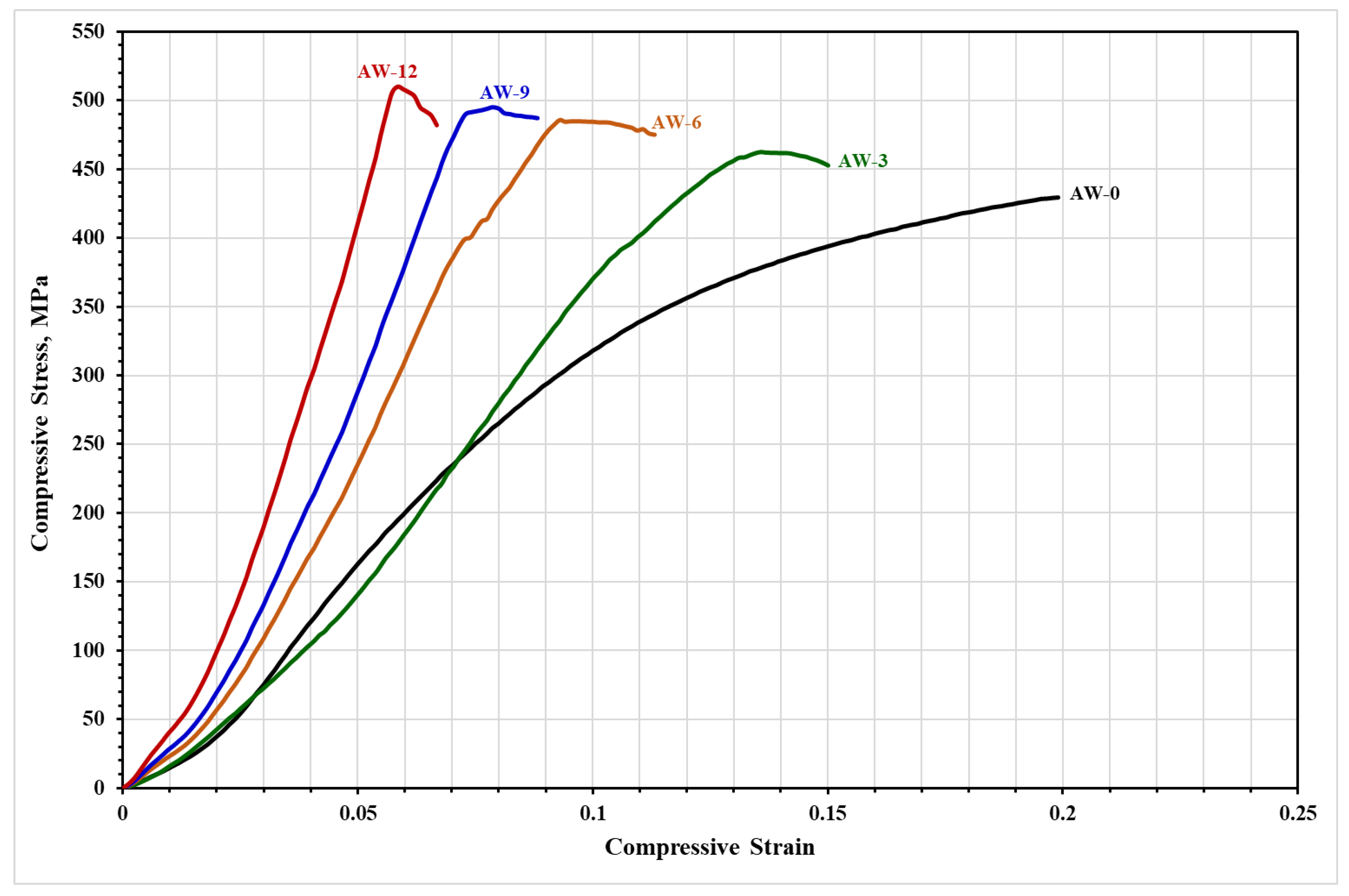
3.4. The Compressive Stress–Strain Behaviour of the Developed AA5083–WC Composites
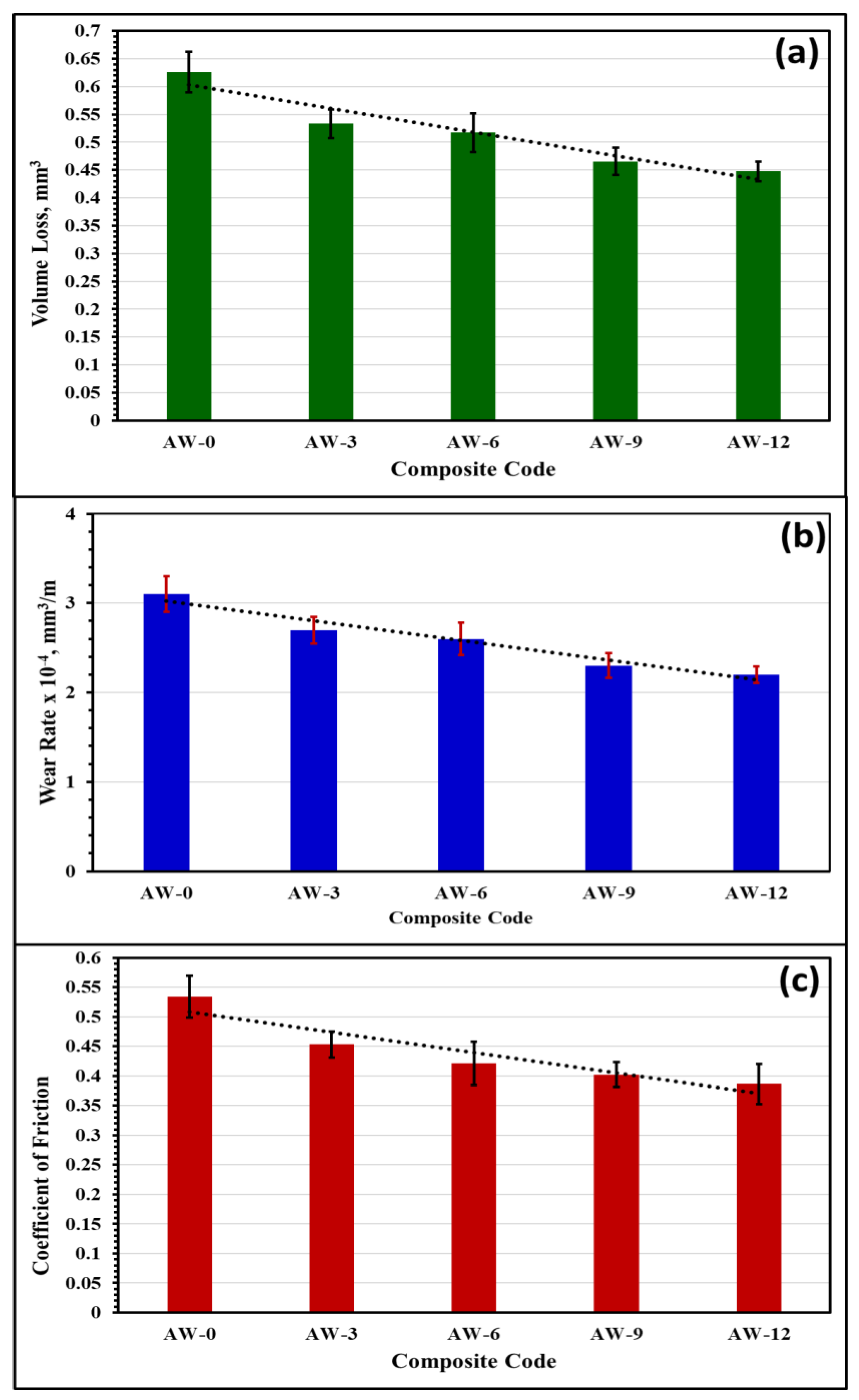
3.5. Tribological Behaviour of the Developed AA5083–WC Composites
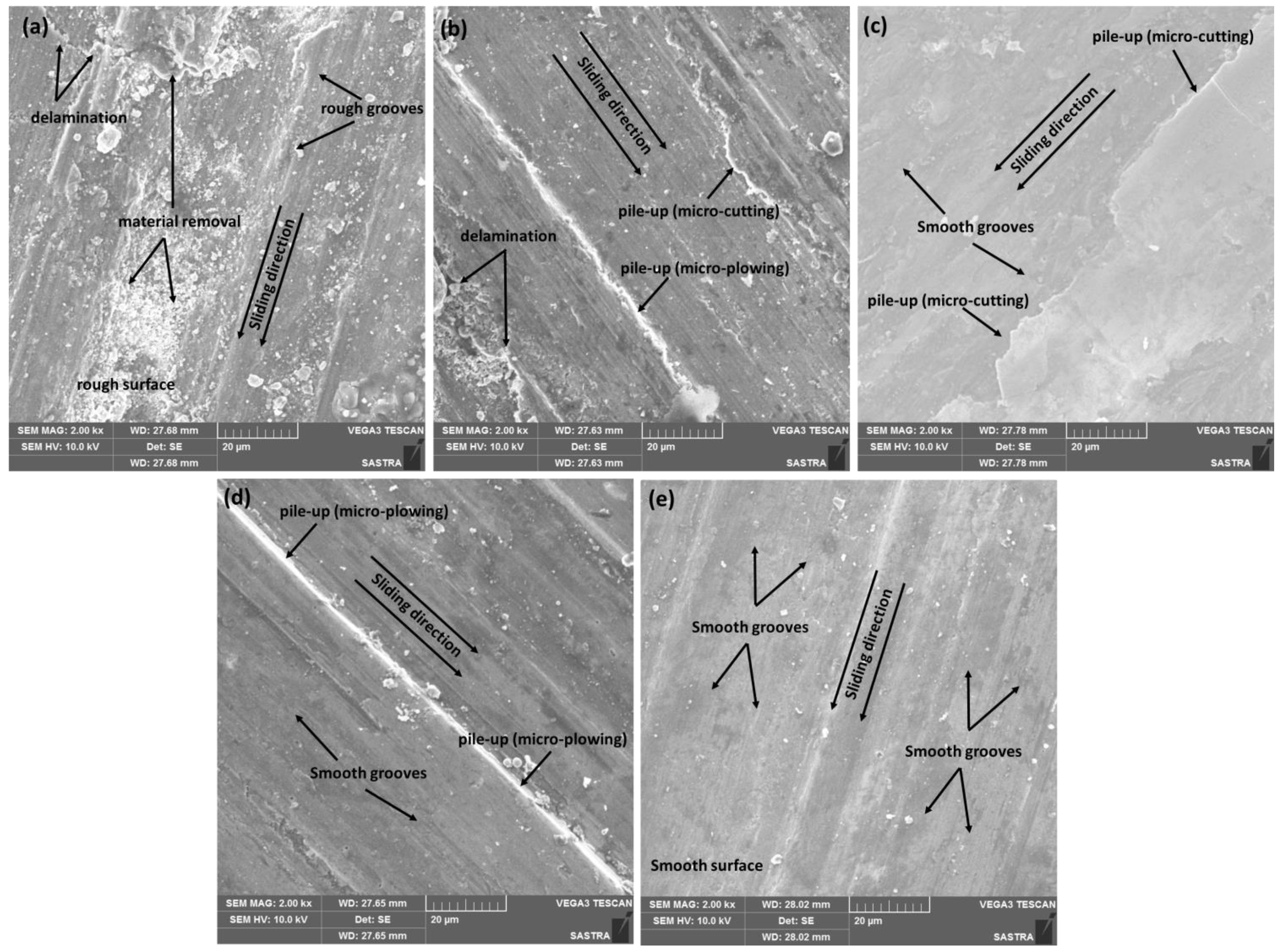
3.6. Worn Surfaces Analysis of the Developed Composites
4. Conclusions
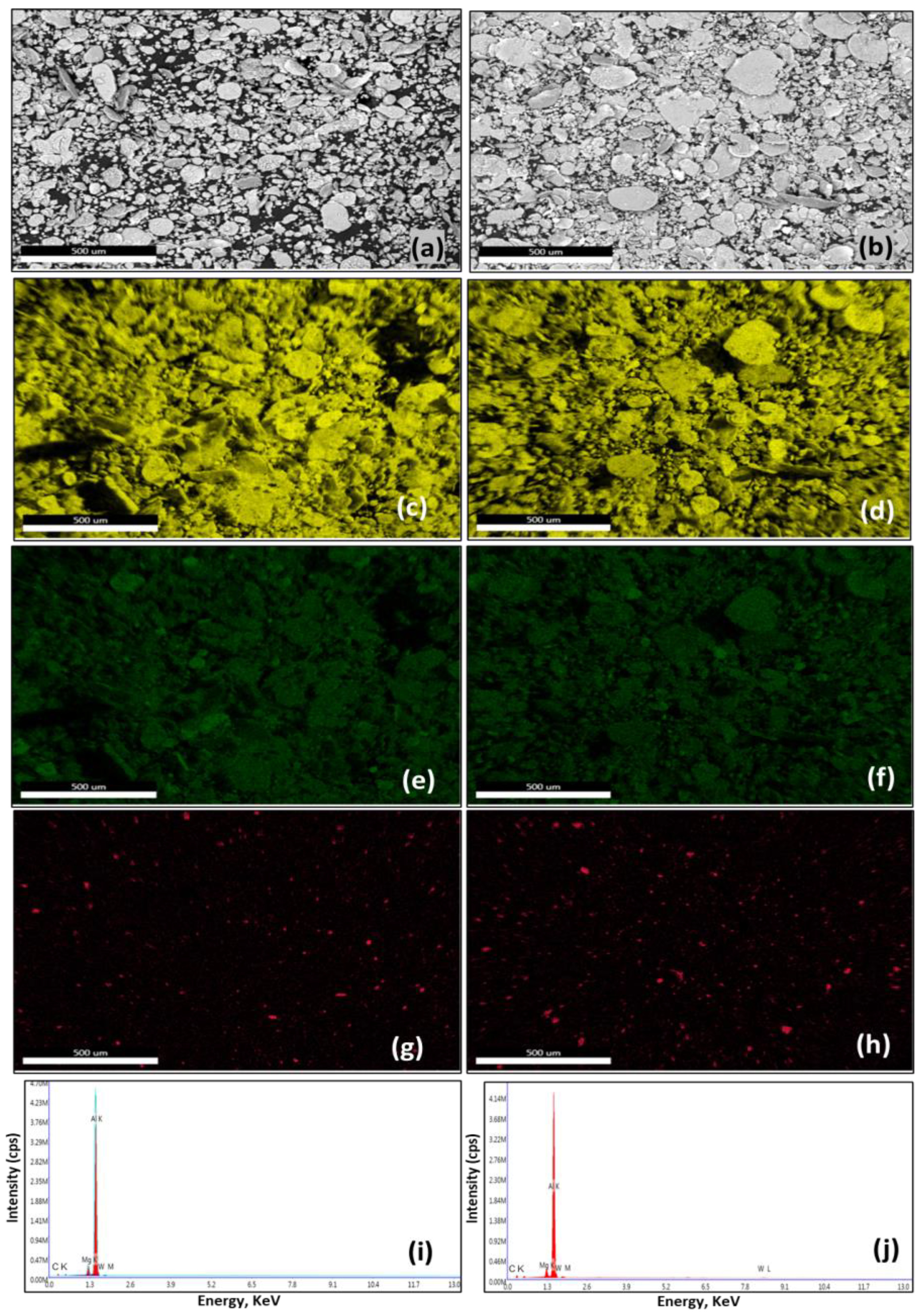
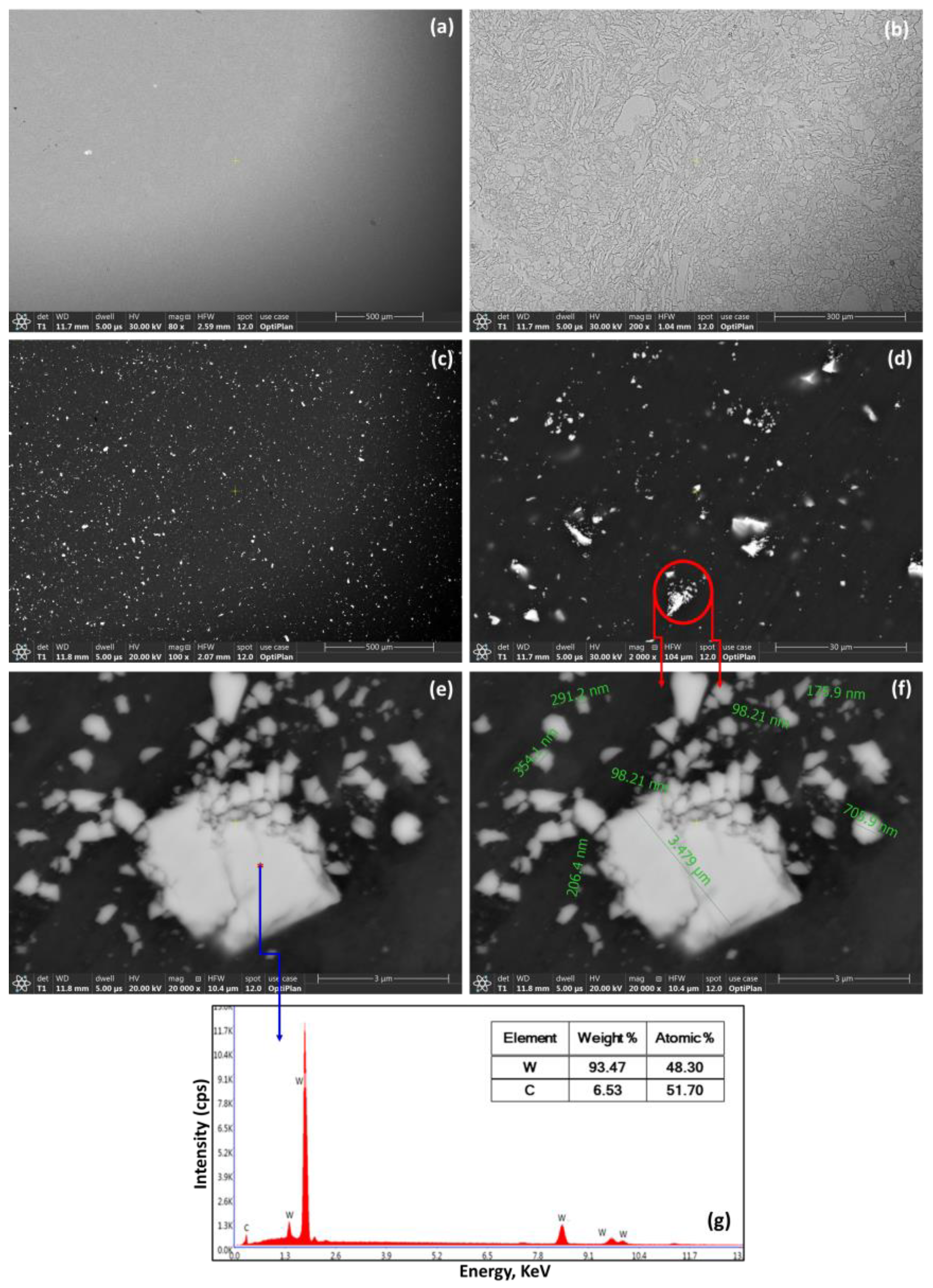
- The developed composites exhibited a homogeneous dispersion of WC particulates in the AA5083 matrix without any interactions at the interface.
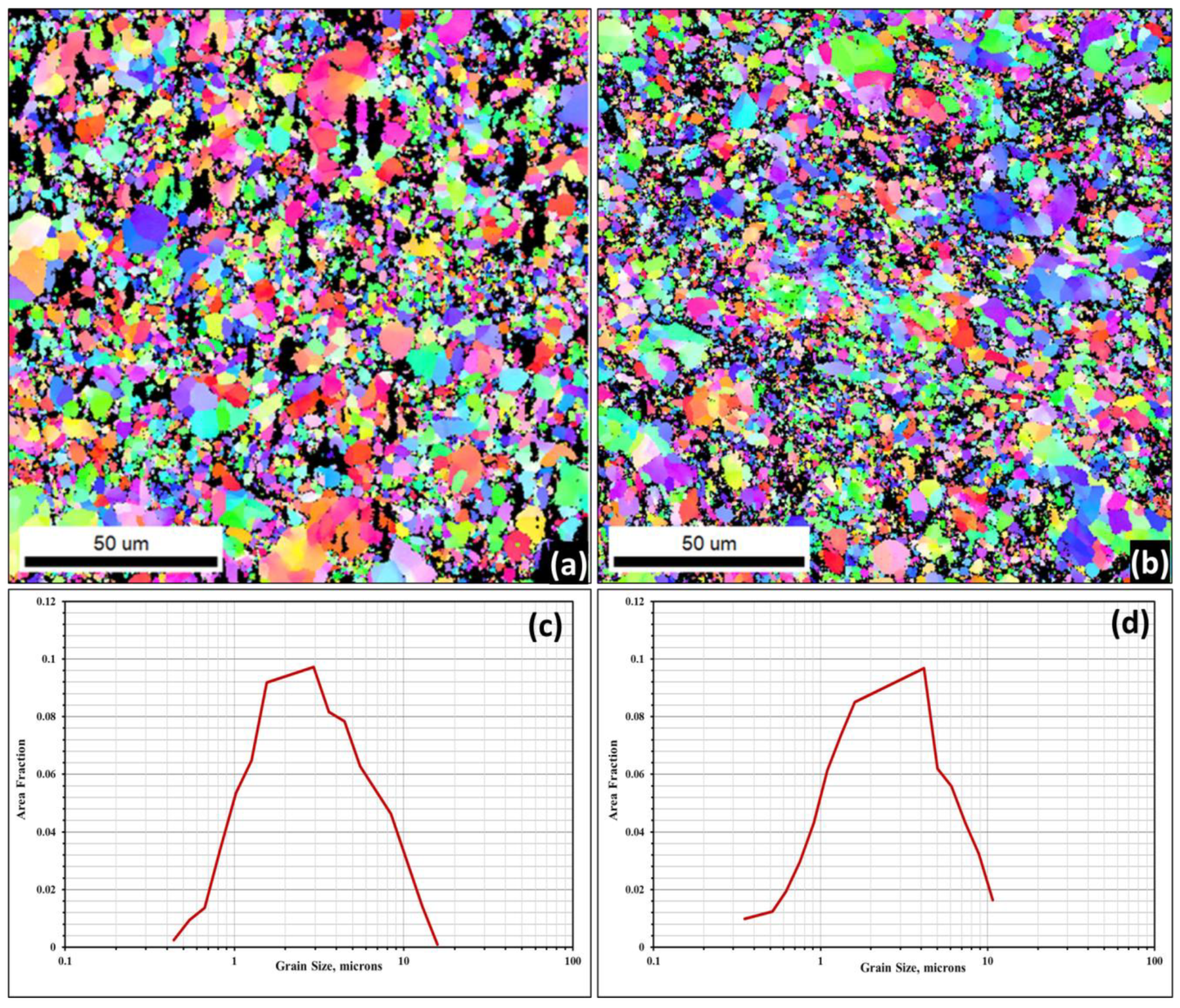
- The EBSD results confirmed the development of a refined equiaxed grain structure of AA5083–WC composites with an average grain size of 4 µm and 3 µm for the AA5083–6%WC (AW-6) and AA5083–12%WC (AW-12) composites, respectively.
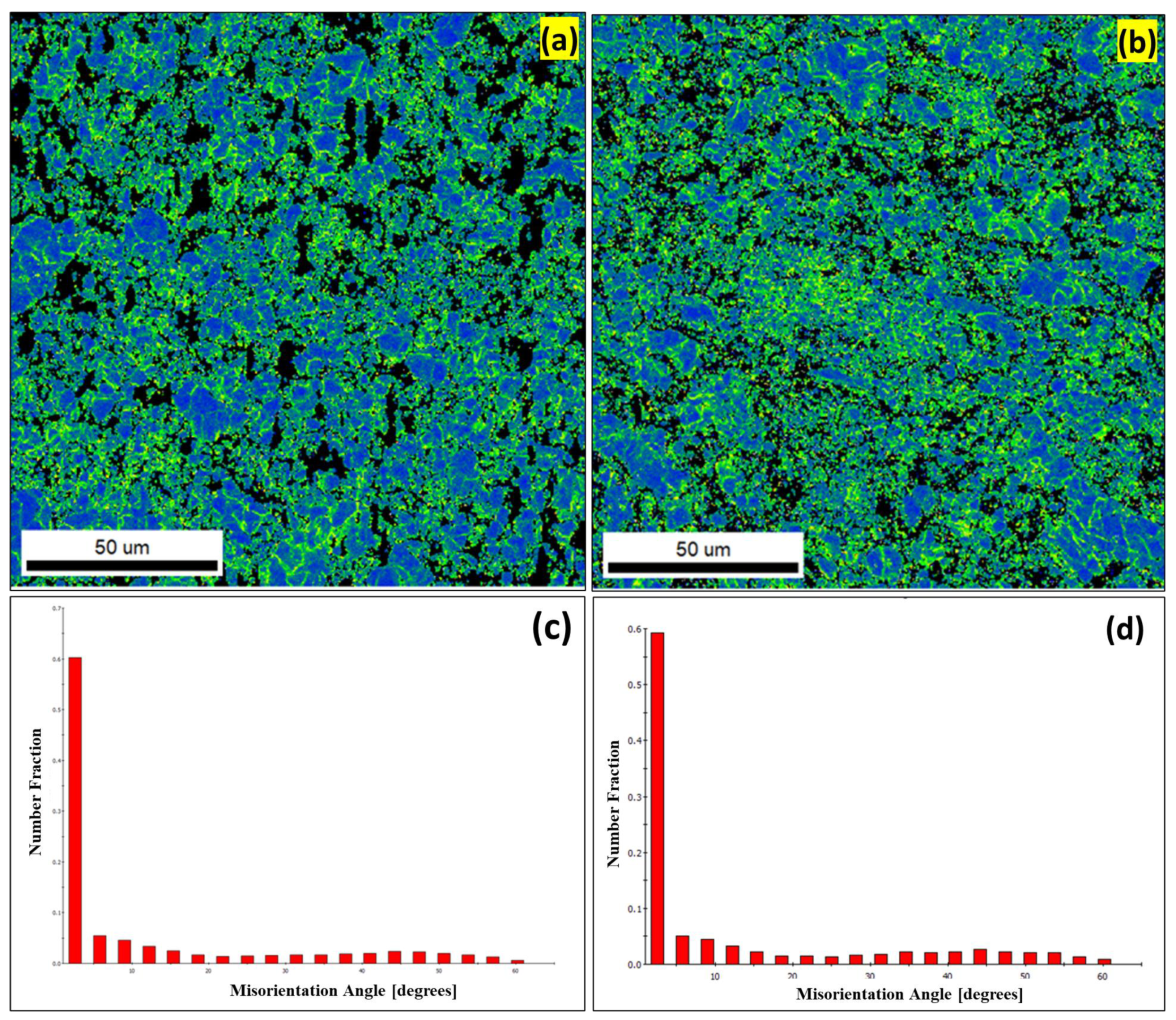
- The Kernel average misorientation map (KAM) and corresponding misorientation angle distributions for the AW-6 and AW-12 composites illustrated that more than 70% were sub-grains (SG) and low-angle grain boundaries (LAGBs) whereas the remaining (<30%) were high angle grain boundaries (HAGBs).
- Increasing the WC content (0–12%) resulted in a considerable enhancement in mechanical and tribological behaviours of the AA5083–WC composites.
- The wear and friction resistance of the composites were observed to increase with increasing the strength and stiffness of the developed composites.
- The AA5083–12%WC composite exhibited the optimum tribological behaviour with the minimum volume loss, lowest wear rate, and lowest friction coefficient.
- The as-milled AA5083 alloy (AW-0) exhibited the minimum wear and friction resistance with the highest volume loss, maximum wear rate, and friction coefficient.
Author Contributions
Funding
Institutional Review Board Statement
Informed Consent Statement
Data Availability Statement
Acknowledgments
Conflicts of Interest
References
- Nieto, A.; Yang, H.; Jiang, L.; Julie, M. Schoenung Reinforcement size effects on the abrasive wear of boron carbide reinforced aluminum composites. Wear 2017, 390–391, 228–235. [Google Scholar] [CrossRef]
- Yuvaraj, N.; Aravindan, S.; Vipin. Wear characteristics of Al5083 surface hybrid nanocomposites by friction stir processing. Trans. Indian Inst. Met. 2017, 70, 1111–1129. [Google Scholar] [CrossRef]
- Poovazhagan, L.; Kalaichelvan, K.; Sornakumar, T. Processing and performance characteristics of aluminum-nano boron carbide metal matrix nanocomposites. Mater. Manuf. Process. 2016, 31, 1275–1285. [Google Scholar] [CrossRef]
- Asl, A.M.; Khandani, S.T. Role of hybrid ratio in microstructural, mechanical and sliding wear properties of the Al5083/Graphitep/Al2O3p a surface hybrid nanocomposite fabricated via friction stir processing method. Mater. Sci. Eng. A 2013, 559, 549–557. [Google Scholar]
- Barenji, R.V.; Khojastehnezhad, V.M.; Pourasl, H.H.; Rabiezadeh, A. Wear properties of Al-Al2O3/TiB2 surface hybrid composite layer prepared by friction stir process. J. Compos. Mater. 2016, 50, 1457–1466. [Google Scholar] [CrossRef]
- Bathula, S.; Saravanan, M.; Dhar, A. Nanoindentation and wear characteristics of Al5083/SiCp nanocomposites synthesized by high energy ball milling and spark plasma sintering. J. Mater. Sci. Technol. 2012, 28, 969–975. [Google Scholar] [CrossRef]
- Reddy, A.P.; Krishna, P.V.; Rao, R.N. Tribological behaviour of Al6061-2SiC-xGr hybrid metal matrix nanocomposites fabricated through ultrasonically assisted stir casting technique. Silicon 2019, 11, 2853–2871. [Google Scholar] [CrossRef]
- Manivannan, I.; Ranganathan, S.; Gopalakannan, S.; Suresh, S. Mechanical properties and tribological behaviour of Al6061- SiC-Gr self-lubricating hybrid nanocomposites. Trans. Indian Inst. Met. 2018, 71, 1897–1911. [Google Scholar] [CrossRef]
- Jeyasimman, D.; Narayanasamy, R.; Ponalagusamy, R.; Anandakrishnan, V.; Kamaraj, M. The effects of various reinforcements on dry sliding wear behaviour of AA 6061 nanocomposites. Mater. Des. 2014, 64, 783–793. [Google Scholar] [CrossRef]
- Mirjavadi, S.S.; Alipour, M.; Emamian, S.; Kord, S.; Hamouda, A.M.S.; Koppad, P.G.; Keshavamurthy, R. Influence of TiO2 nanoparticles incorporation to friction stir welded 5083 aluminum alloy on the microstructure, mechanical properties and wear resistance. J. Alloy. Compd. 2017, 712, 795–803. [Google Scholar] [CrossRef]
- Mirjavadi, S.S.; Alipour, M.; Hamouda, A.M.S.; Matin, A.; Kord, S.; Afshari, B.M.; Koppad, P.G. Effect of multi-pass friction stir processing on the microstructure, mechanical and wear properties of AA5083/ZrO2 nanocomposites. J. Alloy. Compd. 2017, 726, 1262–1273. [Google Scholar] [CrossRef]
- Shinde, D.M.; Sahoo, P.; Davim, J.P. Tribological characterization of particulate-reinforced aluminum metal matrix nanocomposites: A review. Adv. Compos. Lett. 2020, 29, 1–28. [Google Scholar] [CrossRef]
- Yuvaraj, N.; Aravindan, S.; Vipin. Fabrication of Al5083/B4C surface composite by friction stir processing and its tribological characterization. J. Mater. Res. Technol. 2015, 4, 398–410. [Google Scholar] [CrossRef] [Green Version]
- Rana, R.S.; Purohit, R.; Das, S. Tribological behaviour of AA 5083/Micron and Nano SiC composites fabricated by ultrasonic assisted stir casting process. Int. J. Sci. Res. Publ. 2013, 3, 1–7. [Google Scholar]
- Idrisi, A.H.; Mourad, A.-H.I.; Thekkuden, D.T.; Christy, J.V. Wear behaviour of AA 5083/SiC nanoparticle metal matrix composite: Statistical analysis. Mater. Sci. Eng. 2018, 324. [Google Scholar] [CrossRef] [Green Version]
- Singh, R.; Shadab, M.; Dash, A.; Rai, R.N. Characterization of dry sliding wear mechanisms of AA5083/B4C metal matrix composite. J. Braz. Soc. Mech. Sci. Eng. 2019, 41, 98. [Google Scholar] [CrossRef]
- Muthuswamy, P.; Dinakaran, D. Evaluation of mechanical and metallurgical properties of cryo-treated tungsten carbide with 25% cobalt. Mater. Today Proc. 2021, 3463–3469. [Google Scholar] [CrossRef]
- Lou, D.; Hellman, J.; Luhulima, D.; Liimatainen, J.; Lindroos, V.K. Interactions between tungsten carbide (WC) particulates and metal matrix in WC-reinforced composites. Mater. Sci. Eng. A 2003, 340, 155–162. [Google Scholar] [CrossRef]
- Ammar, H.R.; Sivasankaran, S.; Alaboodi, A.S. Investigation of the Microstructure and Compressibility of Biodegradable Fe-Mn-Cu/W/Co Nanostructured Alloy Powders Synthesized by Mechanical Alloying. Materials 2021, 14, 3088. [Google Scholar] [CrossRef]
- Sivasankaran, S.; Ammar, H.R.; Almangour, B.; Elborolosy, S.A.; Mekky, A.B.H.; Alaboodi, A.S. Influence of Milling Time and Ball-to-Powder Ratio on Mechanical Behaviour of FeMn30Cu5 Biodegradable Alloys Prepared by Mechanical Alloying and Hot-Forging. Crystals 2022, 12, 1777. [Google Scholar] [CrossRef]
- Parthasarathi, N.L.; Duraiselvam, M. ASTM Designation: G 99–95a (Reapproved 2000) Standard Test Method for Wear Testing with a Pin-on-Disk Apparatus. J. Miner. Mater. Charact. Eng. 2010, 9, 653–670. [Google Scholar] [CrossRef]
- Santhosh, N.; Praveena, B.A.; Jain, R.; AbulHasan, M.; Islam, S.; Khan, M.A.; Razak, A.; Daniyal, M. Analysis of friction and wear of aluminium AA 5083/ WC composites for building applications using advanced machine learning models. Ain Shams Eng. J. 2022, 102090. [Google Scholar] [CrossRef]
- Ibrahim, M.F.; Ammar, H.R.; Samuel, A.M.; Soliman, M.S.; Samuel, F.H. On the impact toughness of Al-15 vol.% B4C metal matrix composites. Compos. Part B. Eng. 2015, 79, 83–94. [Google Scholar] [CrossRef]
- Bauri, R.; Yadav, D.; Kumar, C.N.S.; Balaji, B. Tungsten particle reinforced Al 5083 composite with high strength and ductility. Mater. Sci. Eng. A 2015, 620, 67–75. [Google Scholar] [CrossRef]
- Suryanarayana, C. Mechanical alloying: A critical review. Mater. Res. Lett. 2022, 10, 619–647. [Google Scholar] [CrossRef]
- Saraf, L. Kernel Average Misorientation Confidence Index Correlation from FIB Sliced Ni-Fe-Cr alloy Surface. Microsc. Microanal. 2011, 17 (Suppl. 2), 424–425. [Google Scholar] [CrossRef] [Green Version]
- Li, H.; Hsu, E.; Szpunar, J.; Utsunomiya, H.; Sakai, T. Deformation mechanism and texture and microstructure evolution during high-speed rolling of AZ31B Mg sheets. J. Mater. Sci. 2008, 43, 7148–7156. [Google Scholar] [CrossRef]
- Sun, S.J.; Tian, Y.Z.; Lin, H.R.; Wang, Z.J.; Zhang, Z.F. Revisiting the role of prestrain history in the mechanical properties of ultrafine-grained CoCrFeMnNi high-entropy alloy. Mater. Sci. Eng. A 2021, 801, 140398. [Google Scholar] [CrossRef]
- Alvi, M.H.; Cheong, S.W.; Suni, J.P.; Weiland, H.; Rollett, A.D. Cube texture in hot-rolled aluminum alloy 1050 (AA1050)—Nucleation and growth behaviour. Acta Mater. 2008, 56, 3098–3108. [Google Scholar] [CrossRef]
- Jata, K.V.; Semiatin, S.L. Continuous dynamic recrystallization during friction stir welding of high strength aluminum alloys. Scr. Mater. 2000, 43, 743–749. [Google Scholar] [CrossRef]
- Gourdet, S.; Montheillet, F. A model of continuous dynamic recrystallization. Acta Mater. 2003, 51, 2685–2699. [Google Scholar] [CrossRef]
- Ghasali, E.; Alizadeh, M.; Ebadzadeh, T.; Pakseresht, A.H.; Rahbari, A. Investigation on microstructural and mechanical properties of B4C-aluminum matrix composites prepared by microwave sintering. J. Mater. Res. Technol. 2015, 4, 411–415. [Google Scholar] [CrossRef] [Green Version]
- Manohar, G.; Pandey, K.M.; Maity, S.R.; Aluminium, M. Matrix Composites Fabricated by Powder Metallurgy Techniques: A Review. In Advances in Material Science and Metallurgy; Pramod, P.B., Desai, U.B., Goel, S., Eds.; Lecture Notes in Mechanical Engineering; Springer: Singapore, 2023. [Google Scholar] [CrossRef]
- Callister, W.D. Fundamentals of Materials Science and Engineering, 2nd ed.; Wiley & Sons: Hoboken, NJ, USA, 2001; p. 252. [Google Scholar]
- Manohar, G.; Maity, S.R.; Pandey, K.M. Microstructural and mechanical properties of microwave sintered AA7075/Graphite/SiC hybrid composite fabricated by powder metallurgy techniques. Silicon 2021. [Google Scholar] [CrossRef]
- Azarniya, A.; Azarniya, A.; Abdollah-zadeh, A.; Madaah Hosseini, H.R.; Ramakrishna, S. In situ hybrid aluminum matrix composites: A review of phase transformations and mechanical aspects. Adv. Eng. Mater. 2019, 21, 1801269. [Google Scholar] [CrossRef]
- Zhai, W.; Bai, L.; Zhou, R.; Fan, X.; Kang, G.; Liu, Y.; Zhou, K. Recent Progress on Wear-Resistant Materials: Designs, Properties, and Applications. Adv. Sci. 2021, 8, 2003739. [Google Scholar] [CrossRef]
- Zambrano, O.A.; Gómez, J.A.; Coronado, J.J.; Rodríguez, S.A. The sliding wear behaviour of steels with the same hardness. Wear 2019, 418–419, 201–207. [Google Scholar] [CrossRef]
- Coronado, J.J.; Holguín, C.A.; Rodríguez, S.A. Sliding wear of weld layers with application to cane mill shaft rebuilding. Proc. Inst. Mech. Eng. Part J. J. Eng. Tribol. 2010, 224, 1283. [Google Scholar] [CrossRef]
- Tan, D.; Mo, J.; He, J.; Luo, J.; Zhang, Q.; Zhu, M.; Zhou, Z. Suitability of laser shock peening to impact-sliding wear in different system stiffnesses. Mech. Eng. Part J. 2019, 208–210, 1994. [Google Scholar] [CrossRef]
- Yao, Q.; Qi, Y.; Zhang, J.; Zhang, S.; Zhao, P.; Wang, H.; Feng, X.-Q.; Li, Q. Impacts of the substrate stiffness on the anti-wear performance of graphene. AIP Adv. 2019, 9, 075317. [Google Scholar] [CrossRef] [Green Version]
- Mazaheri, Y.; Karimzadeh, F.; Enayati, M.H. Tribological Behaviour of A356/Al2O3 Surface Nanocomposite Prepared by Friction Stir Processing. Metall. Mater. Trans. A 2014, 45, 2250–2259. [Google Scholar] [CrossRef]
- Heidarpour, A. Fabrication and Characterization of A5083-WC-Al2O3 Surface Composite by Friction Stir Processing. J. Mater. Eng. Perform. 2019, 28, 2747–2753. [Google Scholar] [CrossRef]
- Chakrapani, P.; Suryakumari, T.S.A. Mechanical properties of aluminium metal matrix composites-A review. Mater. Today Proc. 2021, 45, 5960–5964. [Google Scholar] [CrossRef]
- MRahaman, H.; Mahun, H.M. Characterization of Silicon carbide reinforced aluminium matrix composites. Procedia Eng. 2014, 90, 104–109. [Google Scholar]
- Suresha, R.; Ajith, G.J.; Siddeshkumar, N.G. Investigation on dry sliding wear behaviour of AA5083/nano-Al2O3 metal matrix composites. Rev. De. Metal. 2022, 58, e213. [Google Scholar] [CrossRef]
- Kök, M.; Özdin, K. Wear resistance of aluminium alloy and its composites reinforced by Al2O3 particles. J. Mater. Process. Technol. 2007, 183, 301–309. [Google Scholar] [CrossRef]


| Element | Al | Mg | Mn | Cr | Si | Fe | Cu | Zn | Ti | O |
|---|---|---|---|---|---|---|---|---|---|---|
| Standard (wt.%) * | Bal. | 4.0–4.9 | 0.4–1.0 | 0.05–0.25 | ≤0.4 | ≤0.4 | ≤0.4 | ≤0.4 | ≤0.4 | ≤0.4 |
| Actual (wt.%) | Bal. | 4.71 | 0.7 | 0.19 | 0.07 | 0.16 | 0.04 | 0.06 | ≤0.01 | 0.19 |
| Composite Code | AA5083 | WC | ||
|---|---|---|---|---|
| wt. fr. * | vol. fr. * | wt. fr. | vol. fr. | |
| AW-0 | 1.00 | 1.000 | 0.00 | 0.000 |
| AW-3 | 0.97 | 0.995 | 0.03 | 0.005 |
| AW-6 | 0.94 | 0.989 | 0.06 | 0.011 |
| AW-9 | 0.91 | 0.984 | 0.09 | 0.016 |
| AW-12 | 0.88 | 0.977 | 0.12 | 0.023 |
| Composite Code | Ultimate Compressive Stress (MPa) | Strain at Ultimate Point | Elastic Modulus (MPa) |
|---|---|---|---|
| AW-0 | 429 ± 3 | 0.22 ± 0.002 | 3725 ± 16 |
| AW-3 | 462 ± 3 | 0.15 ± 0.001 | 4060 ± 9 |
| AW-6 | 486 ± 2 | 0.12 ± 0.001 | 4577 ± 13 |
| AW-9 | 495 ± 1 | 0.11 ± 0.001 | 5563 ± 9 |
| AW-12 | 511 ± 2 | 0.08 ± 0.001 | 7778 ± 11 |
Disclaimer/Publisher’s Note: The statements, opinions and data contained in all publications are solely those of the individual author(s) and contributor(s) and not of MDPI and/or the editor(s). MDPI and/or the editor(s) disclaim responsibility for any injury to people or property resulting from any ideas, methods, instructions or products referred to in the content. |
© 2023 by the authors. Licensee MDPI, Basel, Switzerland. This article is an open access article distributed under the terms and conditions of the Creative Commons Attribution (CC BY) license (https://creativecommons.org/licenses/by/4.0/).
Share and Cite
Ammar, H.R.; Sivasankaran, S.; Sherif, E.-S.M.; Almufadi, F.A.; Mekky, A.-b.H. Synthesis, Microstructure Investigation, Mechanical and Tribological Behaviour of the AA5083–WC Composite. Materials 2023, 16, 2891. https://doi.org/10.3390/ma16072891
Ammar HR, Sivasankaran S, Sherif E-SM, Almufadi FA, Mekky A-bH. Synthesis, Microstructure Investigation, Mechanical and Tribological Behaviour of the AA5083–WC Composite. Materials. 2023; 16(7):2891. https://doi.org/10.3390/ma16072891
Chicago/Turabian StyleAmmar, Hany R., Subbarayan Sivasankaran, El-Sayed M. Sherif, Fahad A. Almufadi, and Abdel-baset H. Mekky. 2023. "Synthesis, Microstructure Investigation, Mechanical and Tribological Behaviour of the AA5083–WC Composite" Materials 16, no. 7: 2891. https://doi.org/10.3390/ma16072891