Multifunctional Cement Composites Strain and Damage Sensors Applied on Reinforced Concrete (RC) Structural Elements


Abstract
:1. Introduction
2. Experimental Program and Materials
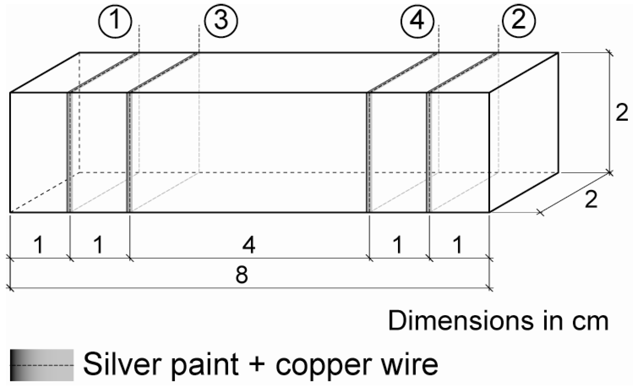
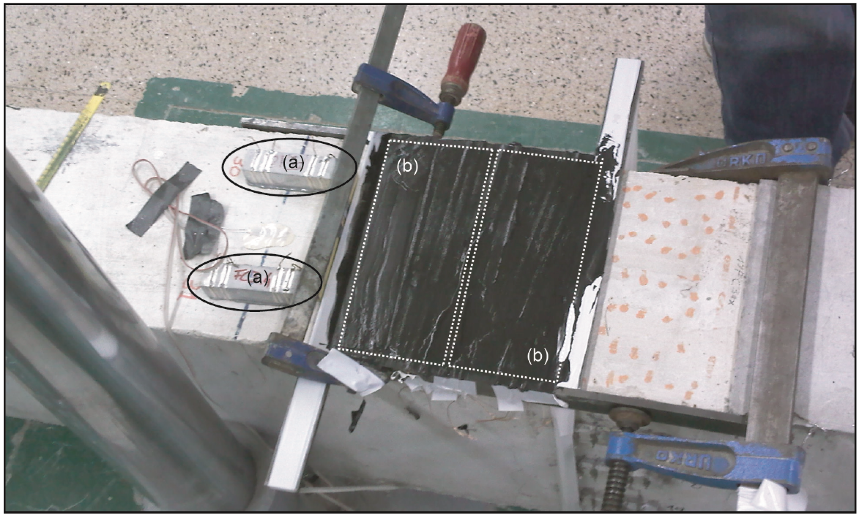
2.1. Sensor’s Preparation

| Property | CNF |
|---|---|
| Fiber diameter (TEM) | 20–80 nm |
| Fiber length (SEM) | >30 µm |
| Bulk density | >1.97 g/cm3 |
| Apparent density | 0.060 g/cm3 |
| Surface energy | ≈100 mJ/m2 |
| Specific surface area BET (N2) | 150–200 m2/g |
| Graphitization degree | ≈70% |
| Resistivity | 1 × 10⁻³ Ω m |
| Metallic particles content | 6%–8% |
| Property | CF3 | CF10 |
|---|---|---|
| Fiber type | PANEX 35 | HEXTOW AS4 |
| Diameter | 7.2 µm | 7.1 µm |
| Length | 3.5 mm | ≈10 mm |
| Carbon content | 95% | 94% |
| Tensile strength | 3800 MPa | 4480 MPa |
| Elastic modulus | 242 GPa | 231 GPa |
| Resistivity | 1.52 × 10⁻³ Ω cm | 1.52 × 10⁻³ Ω cm |
| Density | 1.81 g/cm3 | 1.79 g/cm3 |
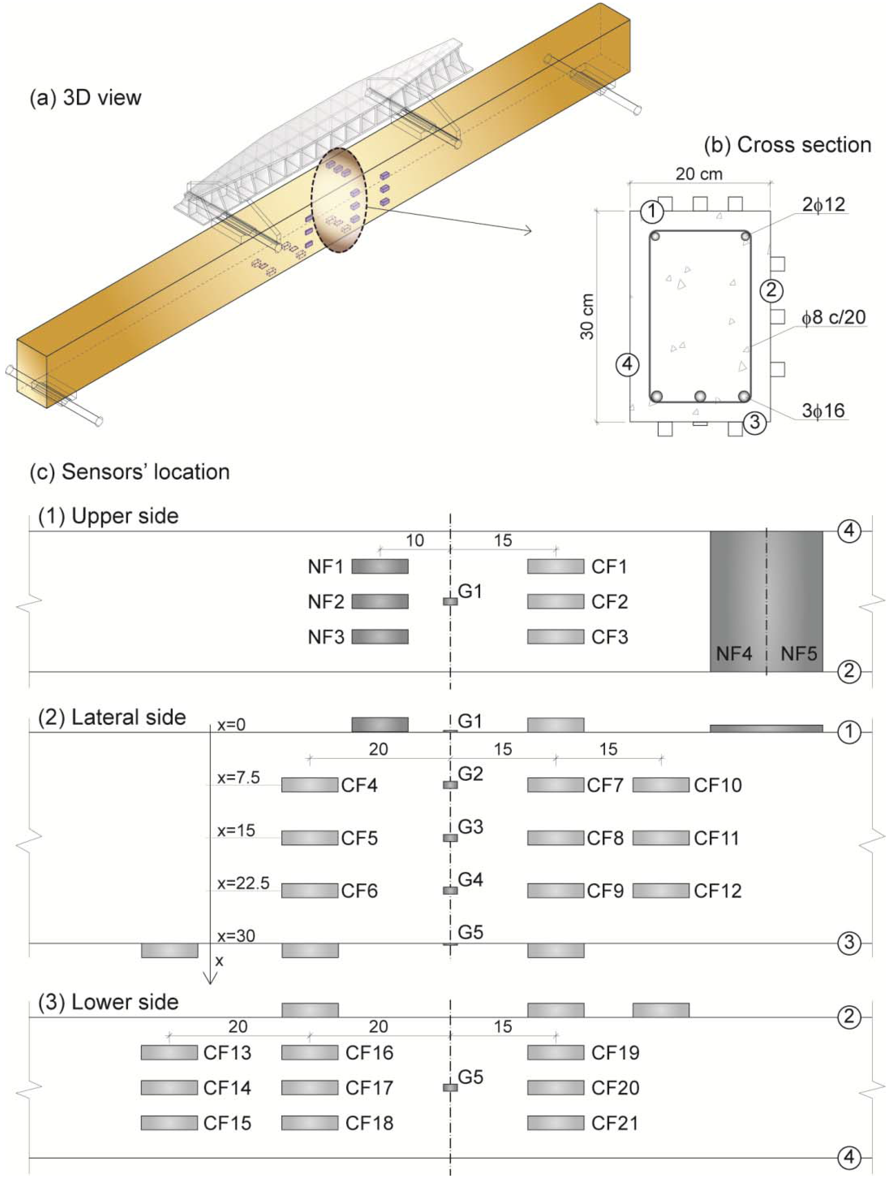
| Sensor | Conductive admixture | Casting method | Width (cm) | Thickness (cm) | Position (x), Depth (cm) |
|---|---|---|---|---|---|
| NF1 | 2% CNF | Attached | 2 | 2 | 0 |
| NF2 | 2% CNF | Attached | 2 | 2 | 0 |
| NF3 | 2% CNF | Attached | 2 | 2 | 0 |
| NF4 | 2% CNF | In situ | 20 | 0.7 | 0 |
| NF5 | 2% CNF | In situ | 20 | 0.7 | 0 |
| CF1 | 1% CF10 | In situ | 2 | 2 | 0 |
| CF2 | 1% CF10 | Attached | 2 | 2 | 0 |
| CF3 | 1% CF10 | In situ | 2 | 2 | 0 |
| CF4 | 1% CF10 | In situ | 2 | 0.5 | 7.5 |
| CF5 | 1% CF10 | In situ | 2 | 0.5 | 15 |
| CF6 | 1% CF10 | In situ | 2 | 0.5 | 22.5 |
| CF7 | 1% CF10 | Attached | 2 | 2 | 7.5 |
| CF8 | 1% CF10 | Attached | 2 | 2 | 15 |
| CF9 | 1% CF10 | Attached | 2 | 2 | 22.5 |
| CF10 | 1% CF10 | In situ | 2 | 2 | 7.5 |
| CF11 | 1% CF10 | In situ | 2 | 2 | 15 |
| CF12 | 1% CF10 | In situ | 2 | 2 | 22.5 |
| CF13 | 1% CF10ox | In situ | 2 | 2 | 30 |
| CF14 | 1% CF10ox | In situ | 2 | 0.5 | 30 |
| CF15 | 1% CF10ox | In situ | 2 | 2 | 30 |
| CF16 | 1% CF10 | In situ | 2 | 2 | 30 |
| CF17 | 1% CF10 | In situ | 2 | 0.5 | 30 |
| CF18 | 1% CF10 | Attached | 2 | 2 | 30 |
| CF19 | 1% CF3ox | In situ | 2 | 2 | 30 |
| CF20 | 1% CF3ox | In situ | 2 | 0.5 | 30 |
| CF21 | 1% CF3ox | In situ | 2 | 2 | 30 |
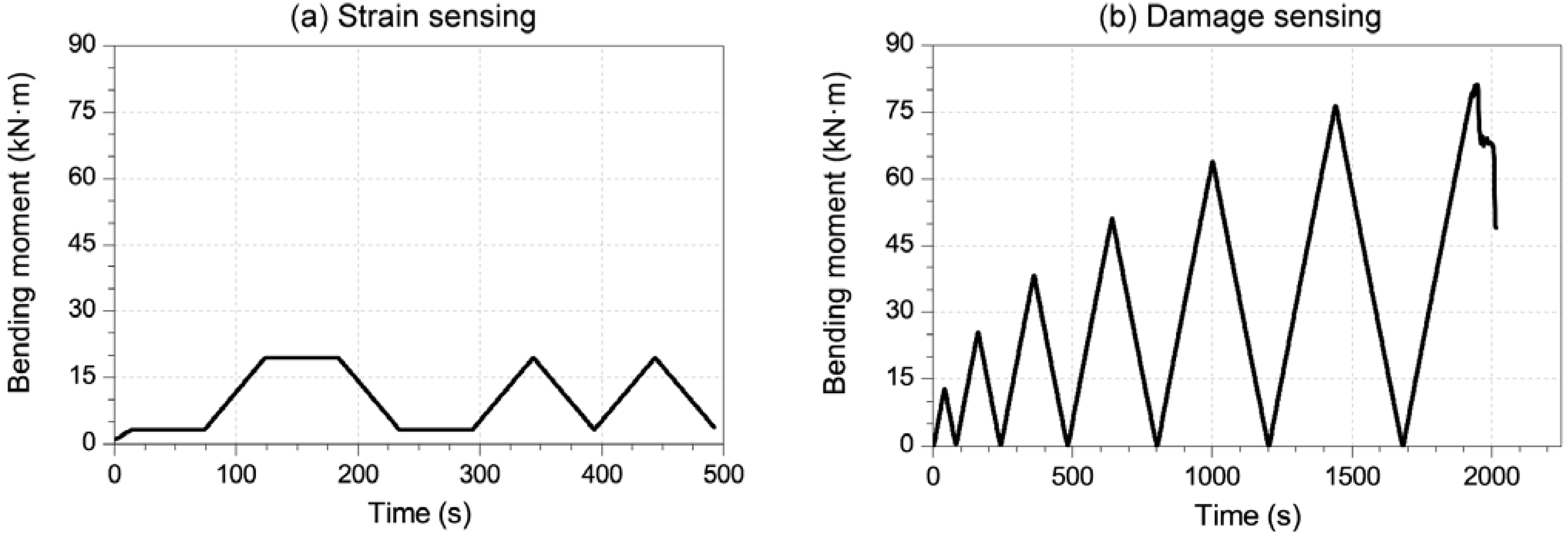
2.2. Strain-Sensing and Damage-Sensing Test Setup
3. Results and Discussion
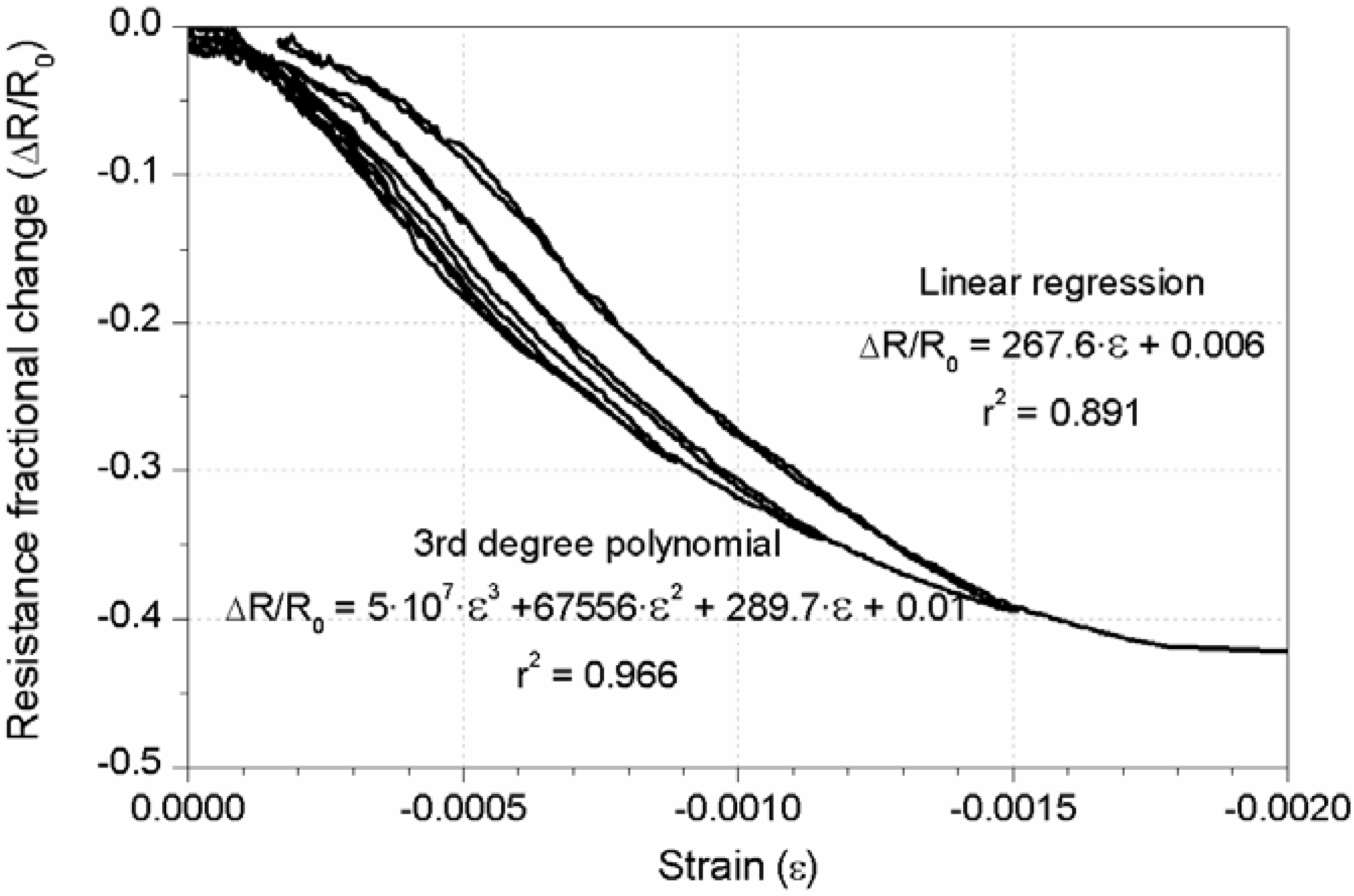
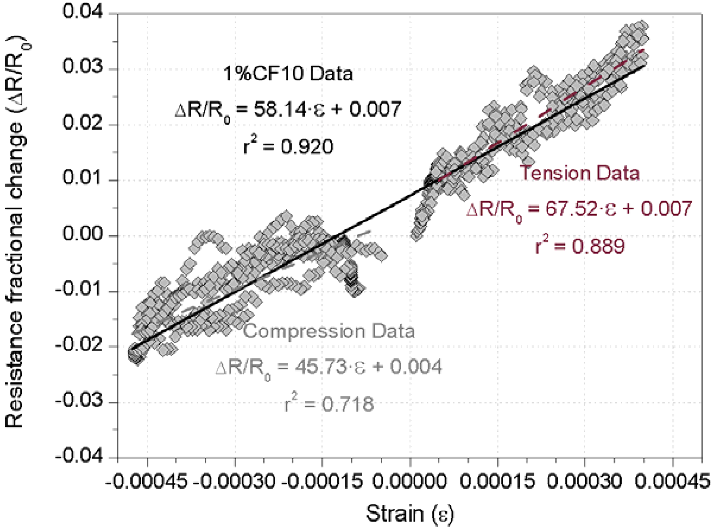
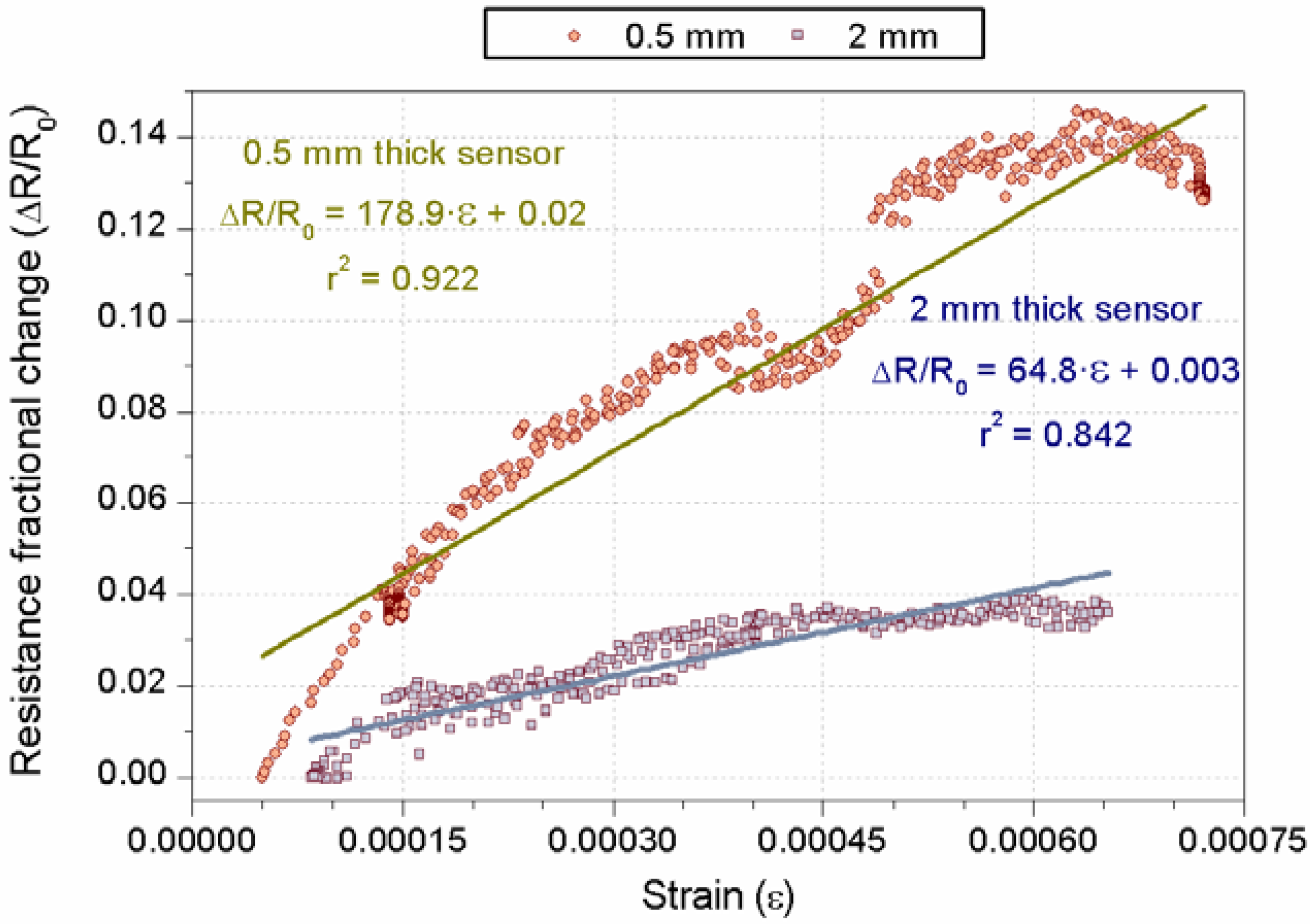
3.1. Strain-Sensing Tests’ Results
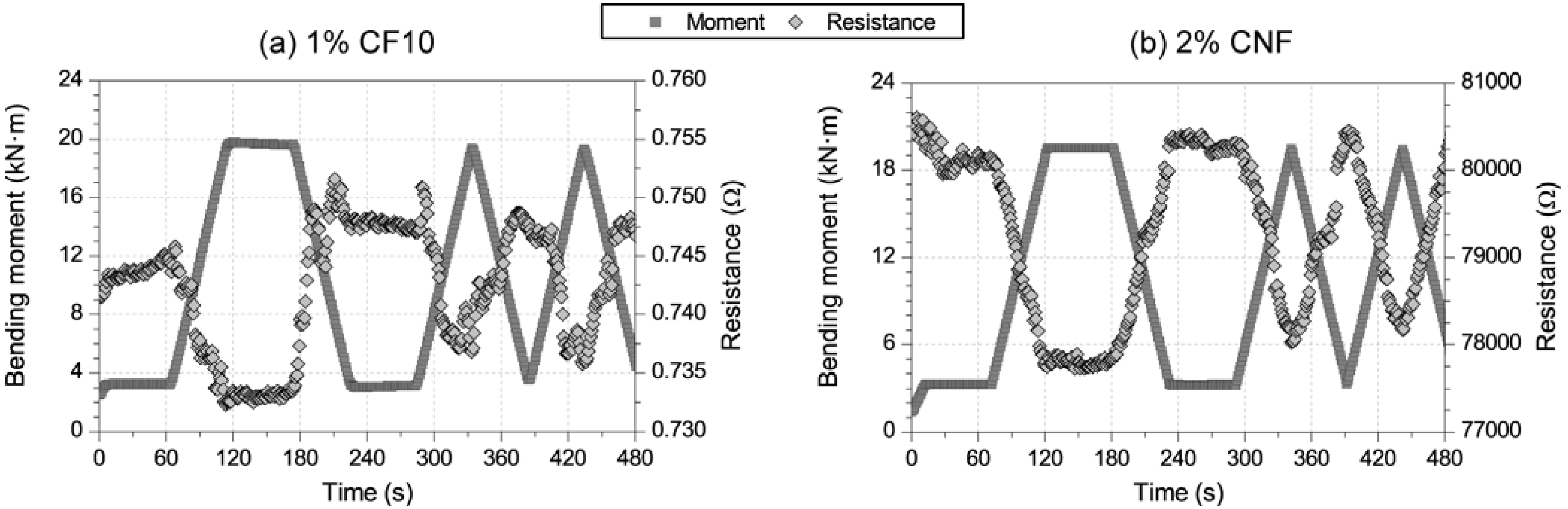


3.2. Damage-Sensing Results


4. Conclusions
Acknowledgments
References
- Baeza, F.J.; Zornoza, E.; Andión, L.G.; Ivorra, S.; Garcés, P. Variables affecting strain sensing function in cementitious composites with carbon fibers. Comput. Concr. 2011, 8, 229–241. [Google Scholar] [CrossRef]
- del Moral, B.; Galao, O.; Antón, C.; Climent, M.A.; Garcés, P. Usability of cement paste containing carbon nanofibers as an anode in electrochemical chloride extraction from concrete. Mater. Constr. 2012. [Google Scholar] [CrossRef]
- Garcés, P.; Carmona, J.; Galao, O.; Zornoza, E.; Climent, M.A. Carbon Nanofibre Cement Paste as Anode for Electrochemical Chloride Removal. In NICOM4 Nanotechnology in Construction, Proceedings of the 4th International Symposium on Nanotechnology in Construction, Agios Nikolaos, Crete, Greece, 20–22 May 2012.
- Pérez, A.; Climent, M.A.; Garcés, P. Electrochemical extraction of chlorides from reinforced concrete using a conductive cement paste as an anode. Corros. Sci. 2010, 52, 1576–1581. [Google Scholar] [CrossRef]
- Zornoza, E.; Galao, O.; Baeza, F.J.; Garcés, P. Electromagnetic Interference Shielding of Cement Pastes with Carbon Nanofibres. In NICOM4 Nanotechnology in Construction, Proceedings of the 4th International Symposium on Nanotechnology in Construction, Agios Nikolaos, Crete, Greece, 20–22 May 2012.
- Zornoza, E.; Catalá, G.; Jiménez, F.; Andión, L.G.; Garcés, P. Electromagnetic interference shielding with Portland cement paste containing carbon materials and processed fly ash. Mater. Constr. 2010, 60, 21–32. [Google Scholar]
- Wu, J.; Chung, D.D.L. Pastes for electromagnetic interference shielding. J. Electron. Mater. 2005, 34, 1255–1258. [Google Scholar] [CrossRef]
- Baeza, F.J.; Chung, D.D.L.; Zornoza, E.; Andión, L.G.; Garcés, P. Triple percolation in concrete reinforced with carbon fiber. ACI Mater. J. 2010, 107, 396–402. [Google Scholar]
- Baeza, F.J. Función de percepción de la deformación en matrices cementicias conductoras mediante adición de fibras de carbono. Ph.D. Thesis, University of Alicante, Spain, December 2011. [Google Scholar]
- Galao, O. Matrices cementicias multifuncionales mediante adición de nanofibras de carbono. Ph.D. Thesis, University of Alicante, Spain, March 2012. [Google Scholar]
- Chung, D.D.L. Multifunctional Cement-Based Materials; Marcel Dekker Inc.: New York, NY, USA, 2003. [Google Scholar]
- Chen, P.W.; Chung, D.D.L. Carbon fiber reinforced concrete as a smart material capable of non-destructive flaw detection. Smart Mater. Struct. 1993, 2, 22–30. [Google Scholar] [CrossRef]
- Chen, P.W.; Chung, D.D.L. Concrete as a new strain/stress sensor. Compos. B Eng. 1996, 27B, 11–23. [Google Scholar] [CrossRef]
- Chung, D.D.L. Cement-matrix composites for thermal engineering. Appl. Therm. Eng. 2001, 21, 1607–1619. [Google Scholar] [CrossRef]
- Galao, O.; Gomis, J.; Zornoza, E.; Baeza, F.J.; Garcés, P. Heating Function of Carbon Nanofibre Cement Pastes. In NICOM4 Nanotechnology in Construction, Proceedings of the 4th International Symposium on Nanotechnology in Construction, Agios Nikolaos, Crete, Greece, 20–22 May 2012.
- Chung, D.D.L. Cement-matrix composites for smart structures. Smart Mater. Struct. 2000, 9, 389–401. [Google Scholar] [CrossRef]
- Chung, D.D.L. Functional properties of cement-matrix composites. J. Mater. Sci. 2001, 36, 1315–1324. [Google Scholar] [CrossRef]
- Reza, F.; Batson, G.B.; Yamamuro, J.A.; Lee, J.S. Resistance changes during compression of carbon fiber cement composites. J. Mater. Civil Eng. 2003, 15, 476–483. [Google Scholar] [CrossRef]
- Chung, D.D.L. Damage in cement-based materials, studied by electrical resistance measurement. Mater. Sci. Eng. R. 2003, 42, 1–40. [Google Scholar] [CrossRef]
- Hou, J.; Chung, D.D.L. Cathodic protection of steel reinforced concrete facilitated by using carbon fiber reinforced mortar or concrete. Cem. Concr. Res. 1997, 27, 649–656. [Google Scholar] [CrossRef]
- Bertolini, L.; Bolzoni, F.; Pastore, T.; Pedeferri, P. Effectiveness of a conductive cementitious mortar anode for cathodic protection of steel in concrete. Cem. Concr. Res. 2000, 34, 681–694. [Google Scholar] [CrossRef]
- Tuan, C.Y.; Yehia, S. Evaluation of electrically conductive concrete containing carbon products for deicing. ACI Mater. J. 2004, 101, 287–293. [Google Scholar]
- Li, G.Y.; Wang, P.M.; Zhao, X. Pressure-sensitive properties and microstructure of carbon nanotube reinforced cement composites. Cem. Concr. Compos. 2007, 29, 377–382. [Google Scholar] [CrossRef]
- Yu, X.; Kwon, E. A carbon nanotube/cement composite with piezoresistive properties. Smart Mater. Struct. 2009, 18, 055010:1–055010:5. [Google Scholar]
- Han, B.G.; Yu, X.; Kwon, E. A self-sensing carbon nanotube/cement composite for traffic monitoring. Nanotechnology 2009, 20, 445501:1–445501:5. [Google Scholar]
- Saafi, M. Wireless and embedded carbon nanotube networks for damage detection in concrete structures. Nanotechnology 2009, 20, 395502:1–395502:7. [Google Scholar] [CrossRef]
- Howser, R.N.; Dhonde, H.B.; Mo, Y.L. Self-sensing of carbon nanofiber concrete columns subjected to reversed cyclic loading. Smart Mater. Struct. 2011, 20, 085031:1–085031:13. [Google Scholar]
- Galao, O.; Zornoza, E.; Baeza, F.J.; Bernabeu, A.; Garcés, P. Effect of carbon nanofiber addition in the mechanical properties and durability of cementitious materials. Mater. Constr. 2012, 62, 343–357. [Google Scholar]
- Alcaide, J.; Alcocel, E.; Puertas, F.; Lapuente, R.; Garcés, P. Carbon fibre-reinforced, alkali-activated slag mortars. Mater. Constr. 2007, 57, 33–48. [Google Scholar]
- Ivorra, S.; Garcés, P.; Catalá, G.; Andión, L.G.; Zornoza, E. Effect of silica fume particle size on mechanical properties of short carbon fiber reinforced concrete. Mater. Design 2010, 31, 1553–1558. [Google Scholar] [CrossRef]
- Catalá, G.; Ramos-Fernández, E.V.; Zornoza, E.; Andión, L.G.; Garcés, P. Influence of the oxidation process of carbon materials on the mechanical properties of cement mortars. J. Mater. Civil Eng. 2011, 23, 321–329. [Google Scholar] [CrossRef]
- Garcés, P.; Fraile, J.; Vilaplana-Ortego, E.; Cazorla, D.; Alcocel, E.G.; Andión, L.G. Effect of carbon fibers on the mechanical properties and corrosion levels of reinforced Portland cement mortars. Cem. Concr. Res. 2005, 35, 324–331. [Google Scholar] [CrossRef]
- Garcés, P.; Zornoza, E.; Alcocel, E.G.; Galao, O.; Andión, L.G. Mechanical properties and corrosion of CAC mortars with carbon fibers. Constr. Build. Mater. 2012, 34, 91–96. [Google Scholar] [CrossRef]
- Garcés, P.; Andión, L.G.; Varga, I.; Catalá, G.; Zornoza, E. Corrosion of steel reinforcement in structural concrete with carbon material addition. Corros. Sci. 2007, 49, 2557–2566. [Google Scholar] [CrossRef]
- Chung, D.D.L. Cement-matrix structural nanocomposites. Met. Mater. Int. 2004, 10, 55–67. [Google Scholar] [CrossRef]
- Sanchez, F.; Ince, C. Microstructure and macroscopic properties of hybrid carbon nanofiber/silica fume cement composites. Compos. Sci. Technol. 2009, 69, 1310–1318. [Google Scholar] [CrossRef]
- Tyson, B.M.; Abu Al-Rub, R.K.; Yazdanbakhsh, A.; Grasley, Z. Carbon nanotubes and carbon nanofibers for enhancing the mechanical properties of nanocomposite cementitious materials. J. Mater. Civil Eng. 2011, 23, 1028–1035. [Google Scholar] [CrossRef]
- Bortz, D.R.; Merino, C.; Martin-Gullon, I. Carbon nanofibers enhance the fracture toughness and fatigue performance of a structural epoxy system. Compos. Sci. Technol. 2011, 71, 31–38. [Google Scholar] [CrossRef]
- Soroushian, P.; Nagi, M.; Okwegbu, A. Freeze-thaw durability of lightweight carbon-fiber reinforced cement composite. ACI Mater. J. 1992, 89, 491–494. [Google Scholar]
© 2013 by the authors. Licensee MDPI, Basel, Switzerland. This article is an open access article distributed under the terms and conditions of the Creative Commons Attribution license ( http://creativecommons.org/licenses/by/3.0/).
Share and Cite
Baeza, F.J.; Galao, O.; Zornoza, E.; Garcés, P. Multifunctional Cement Composites Strain and Damage Sensors Applied on Reinforced Concrete (RC) Structural Elements. Materials 2013, 6, 841-855. https://doi.org/10.3390/ma6030841
Baeza FJ, Galao O, Zornoza E, Garcés P. Multifunctional Cement Composites Strain and Damage Sensors Applied on Reinforced Concrete (RC) Structural Elements. Materials. 2013; 6(3):841-855. https://doi.org/10.3390/ma6030841
Chicago/Turabian StyleBaeza, Francisco Javier, Oscar Galao, Emilio Zornoza, and Pedro Garcés. 2013. "Multifunctional Cement Composites Strain and Damage Sensors Applied on Reinforced Concrete (RC) Structural Elements" Materials 6, no. 3: 841-855. https://doi.org/10.3390/ma6030841