From Powders to Dense Metal Parts: Characterization of a Commercial AlSiMg Alloy Processed through Direct Metal Laser Sintering

 ,
,
Abstract
:
1. Introduction
- •
- Indirect processing, using metal powders mixed with polymer binders;
- •
- Liquid-phase sintering, using a mixture of two metal powders or a metal alloy;
- •
- Full melting, the most recently developed method, using a single metal powder that is fully melted, as the name implies.
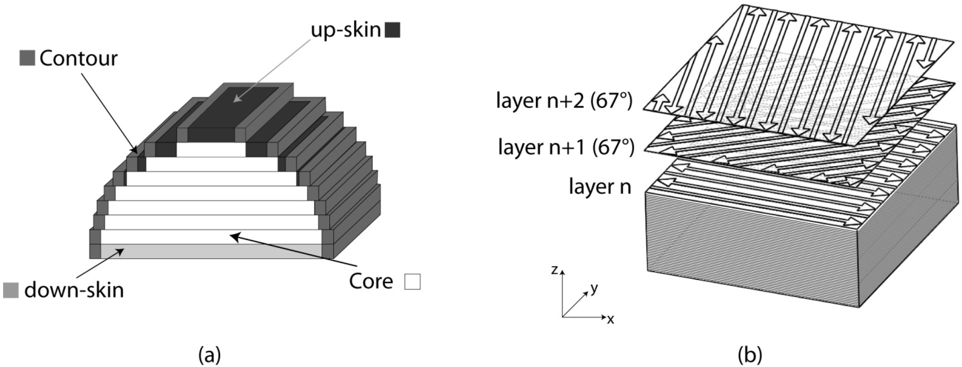
2. Materials and Methods

| Parameters | Skin | Core | Contour |
|---|---|---|---|
| Scan speed (v) [mm/s] | 900 | 800 | 900 |
| Laser power (P) [W] | 120 | 195 | 80 |
| Hatching distance (hd) [mm] | 0.1 | 0.17 | – |
| Layer thickness [μm] | 30 | 30 | – |
| Laser spot size [mm] | 0.01 | 0.01 | 0.01 |
3. Results
3.1. Powder Characterization


| Element | Weight (%) |
|---|---|
| Si | 10.08 |
| Fe | 0.16 |
| Cu | 0.001 |
| Mn | 0.002 |
| Mg | 0.35 |
| Zn | 0.002 |
| Ti | 0.01 |
| Al | balance |
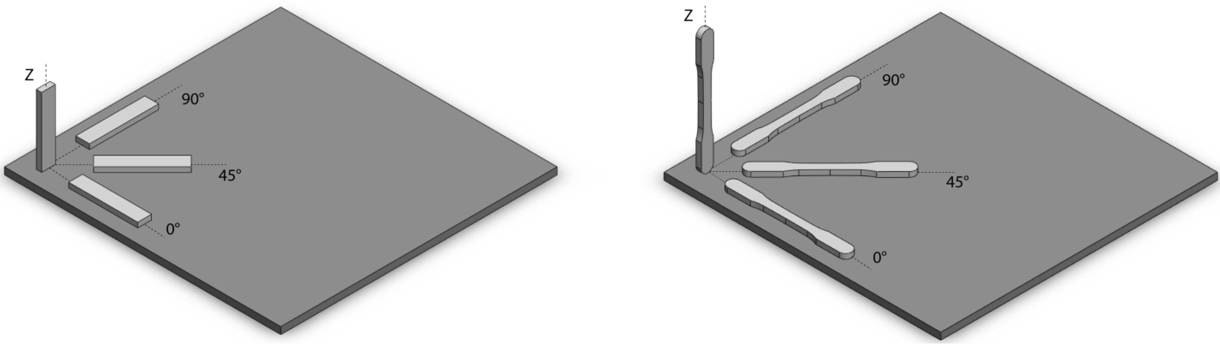
3.2. Mechanical Characterization
| Orientation | Density (g/cm3) | Residual Porosity (%) | Hardness (HV) | Young’s Modulus E (GPa) |
|---|---|---|---|---|
| xy-plane | 2.66 | 0.8 | 105 ± 2 | 73 ± 1 |
| z axis | 2.66 | 0.7 | 108 ± 3 | 72 ± 1 |
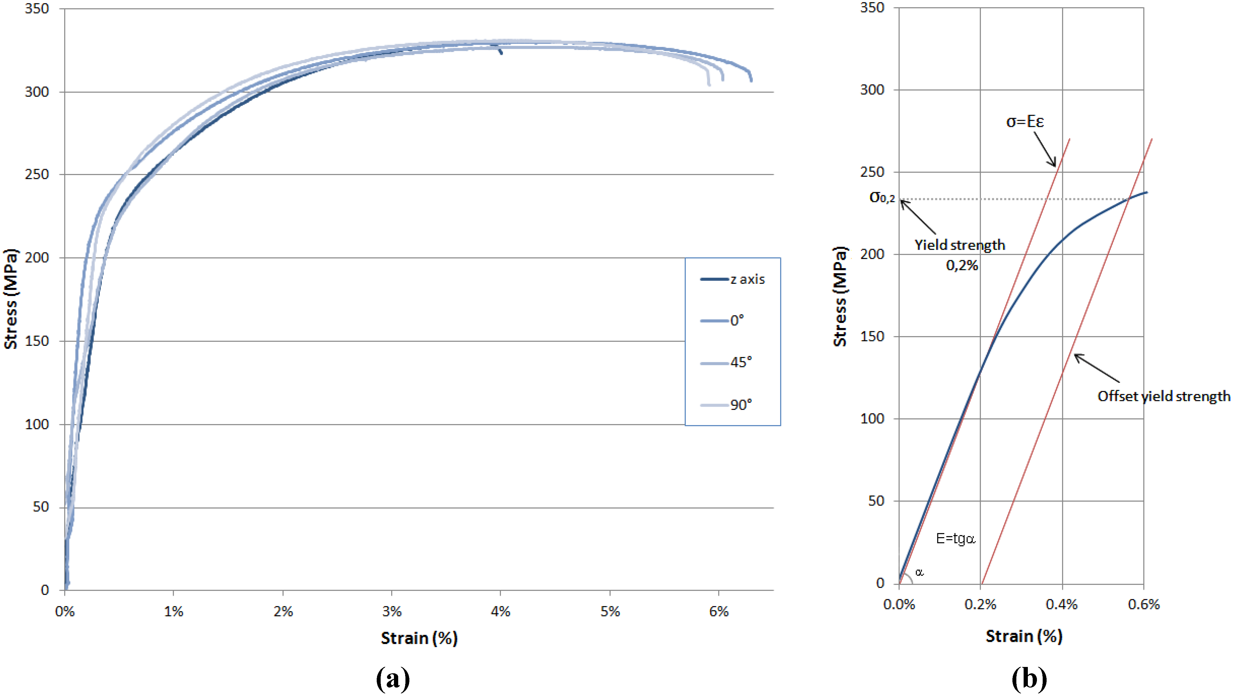
| Material | Orientation | Yield Strength σ0.2 (MPa) | Ultimate Tensile Strength σUTS (MPa) | Elongation at break (%) |
|---|---|---|---|---|
| AlSiMg after DMLS | xy-plane | 243 ± 7 | 330 ± 3 | 6.2 ± 0.3 |
| z axis | 231 ± 3 | 329 ± 2 | 4.1 ± 0.2 | |
| A360.0 F * | – | 170 | 317 | 5 |

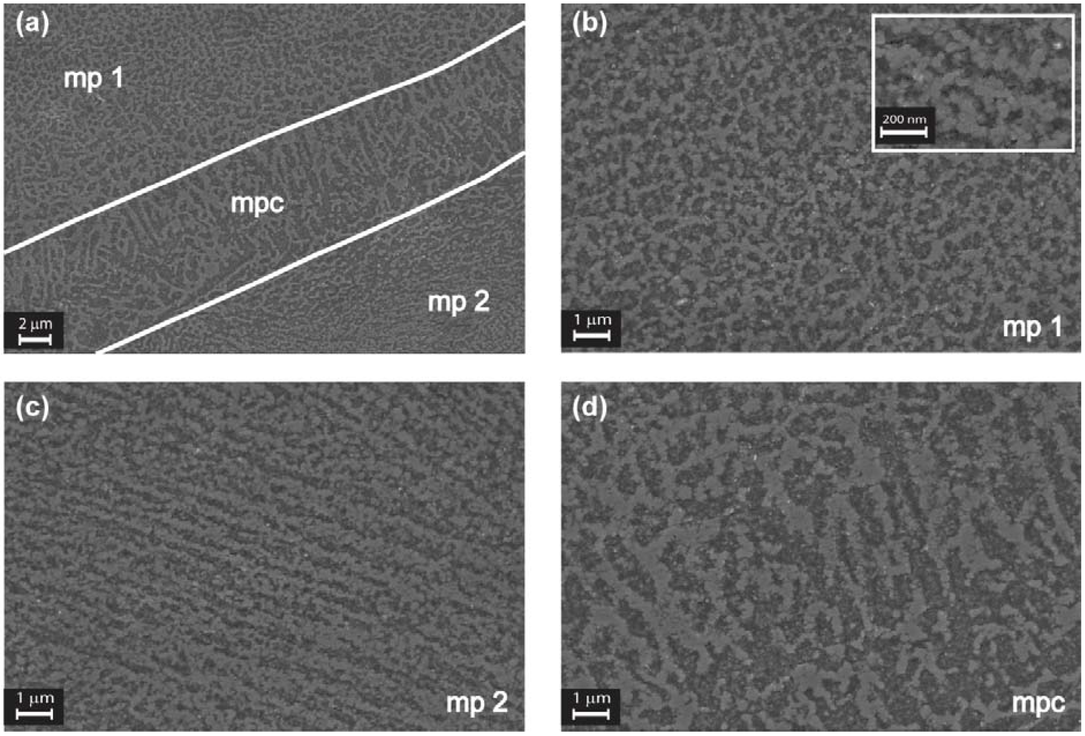
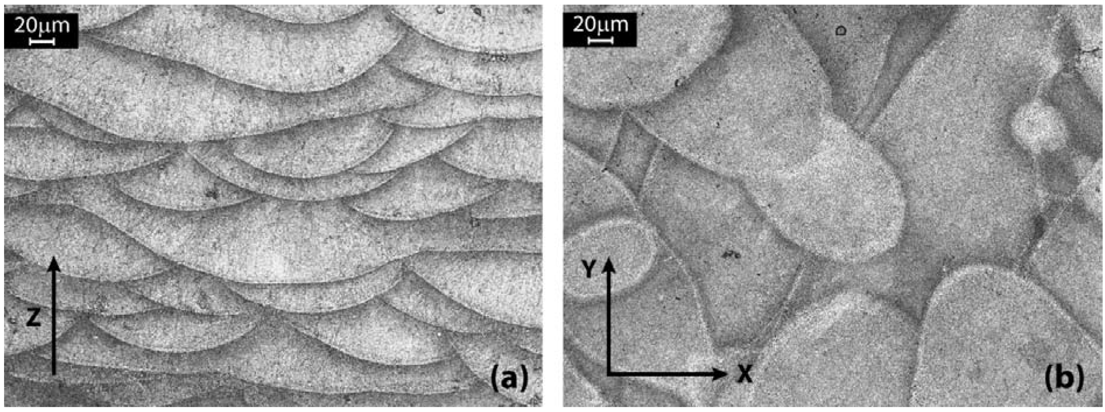
3.3. Microstructure and Fracture Surface Analyses

4. Discussion
5. Conclusions
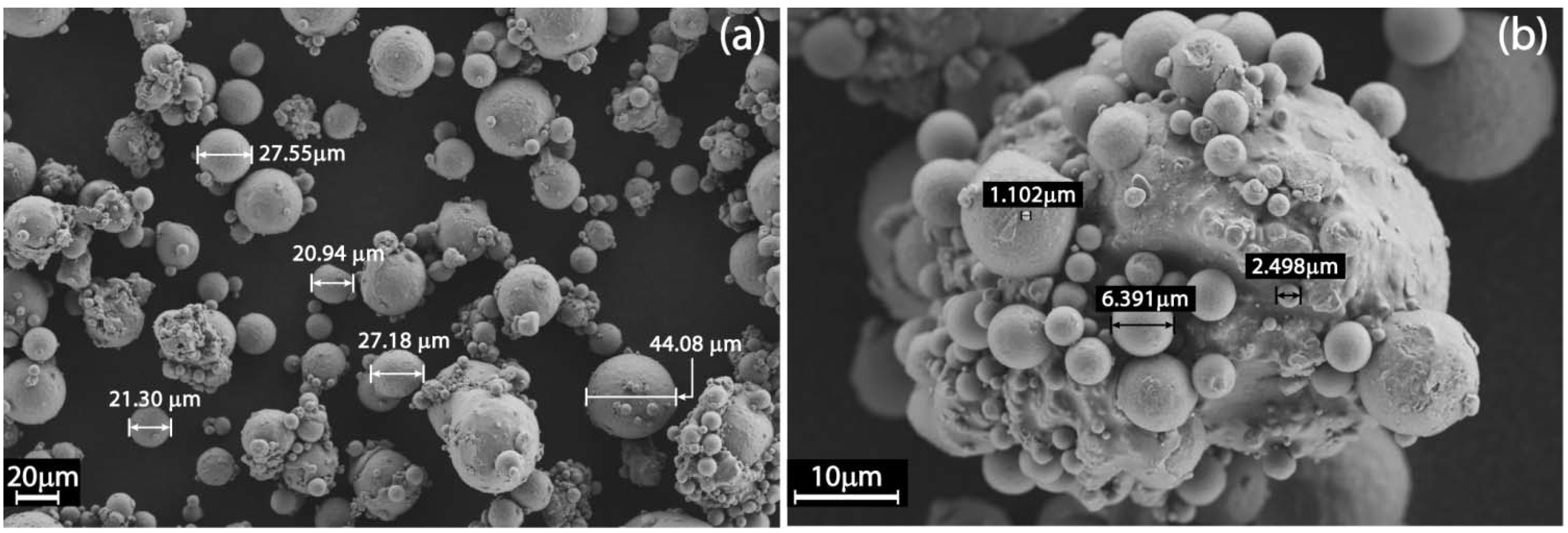
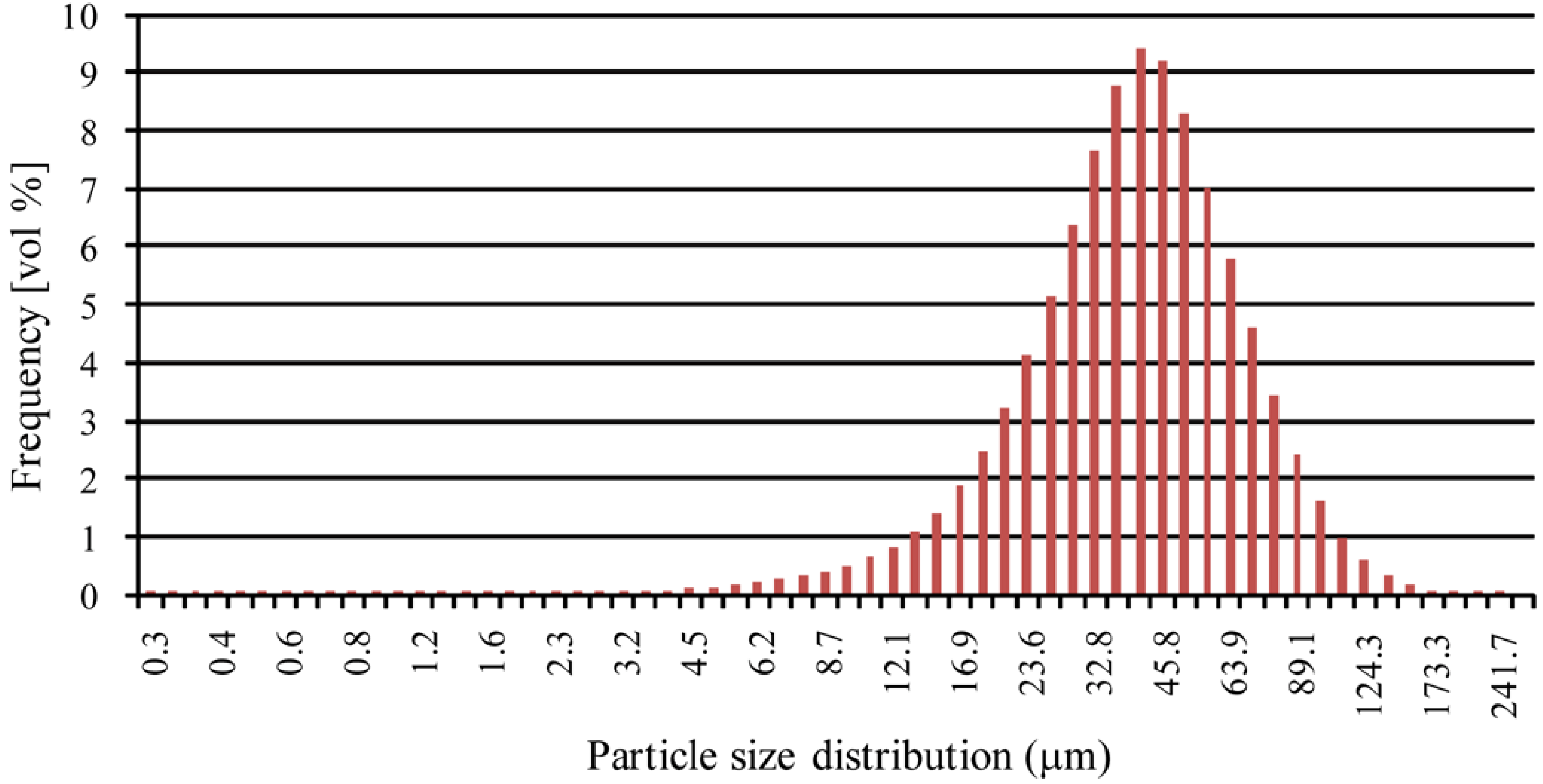
- The AlSiMg powders employed in this study are spherical in shape with an average size of 21–27 µm, but very fine particles with a diameter lower than 10 µm tend to agglomerate, forming bigger clusters of irregular shape. These clusters can adversely affect the flowability of the powders: so, it is fundamental to sieve them before starting the DMLS process.
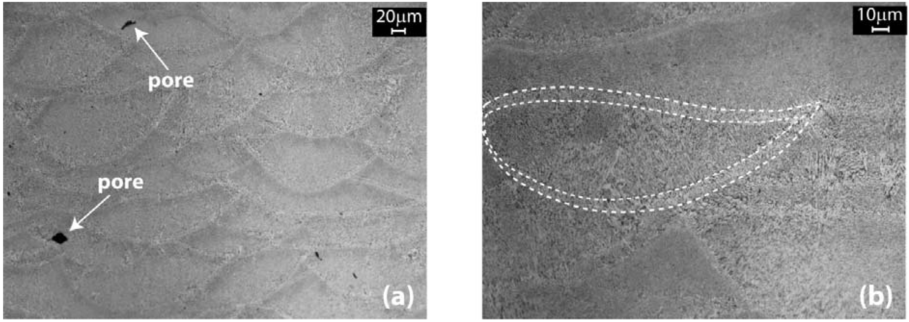
- Density evaluation of samples indicates a residual porosity of about 0.8%. Microscopic observations show that porosities are very small, on the order of 20 to 30 µm.
- In comparison to the properties of a commercial as-cast A360.0 alloy, AlSiMg DMLS specimens show very high values of yield strength, with an enhancement of about 43% for samples built in the xy-plane and 36% for samples along the z axis. The ultimate tensile strength is slightly higher in both cases, while for the elongation at break, there is an enhancement on the xy-plane and a small decrease along the build direction.
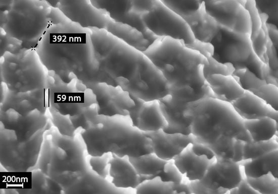
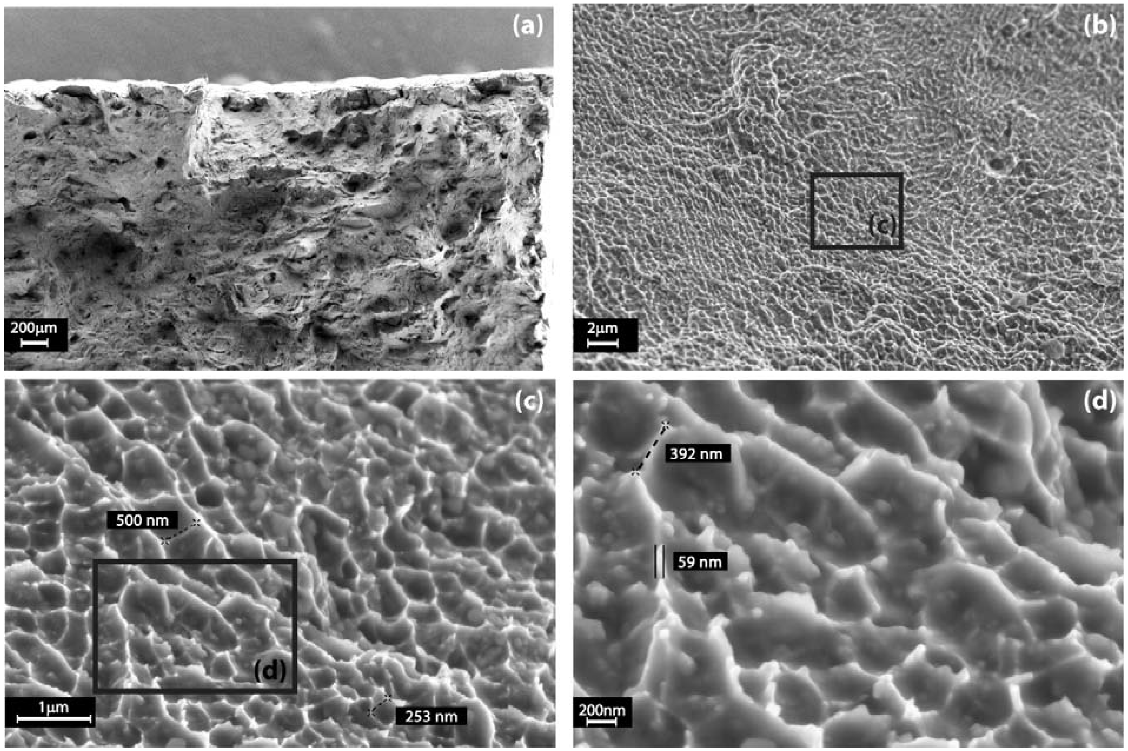
- Microstructure observations show a very fine cellular-dendritic structure by agglomerates of grains with mean diameters of about 80 nm, responsible for the superior overall mechanical properties without the need for a further heat treatment.
- Fracture’s surfaces analysis reveals also a very peculiar behavior: the fracture was caused by coalescence of submicrometric voids, with dimples of nanometric thickness.
Acknowledgments
References
- Atzeni, E.; Salmi, A. Economics of additive manufacturing for end-usable metal parts. Int. J. Adv. Manuf. Tech. 2012, 62, 1147–1155. [Google Scholar] [CrossRef]
- Tuck, C.; Hague, R. The pivotal role of rapid manufacturing in the production, of cost-effective customised products. Int. J. Mass Cust. 2006, 1, 360–373. [Google Scholar]
- Kathuria, Y.P. Microstructuring by selective laser sintering of metallic powder. Surf. Coat. Technol. 1999, 116–119, 643–647. [Google Scholar] [CrossRef]
- Hopkinson, N.; Hague, R.J.M.; Dickens, P.M. Rapid Manufacturing: An Industrial Revolution for the Digital Age; Wiley: New York, NY, USA, 2006. [Google Scholar]
- Gibson, I.; Rosen, D.W.; Stucker, B. Design for Additive Manufacturing. In Additive Manufacturing Technologies, 1st ed.; Springer: New York, NY, USA, 2010; pp. 283–316. [Google Scholar]
- Simchi, A.; Pohl, H. Effects of laser sintering processing parameters on the microstructure and densification of iron powder. Mater. Sci. Eng. A 2003, 359, 119–128. [Google Scholar] [CrossRef]
- Simchi, A.; Petsoldt, F.; Pohl, H. On the development of direct metal laser sintering for rapid tooling. J. Mater. Process. Tech. 2003, 141, 319–328. [Google Scholar] [CrossRef]
- Kumar, S. Selective laser sintering: A qualitative and objective approach. JOM 2003, 55, 43–47. [Google Scholar] [CrossRef]
- Simchi, A. Direct laser sintering of metal powders: Mechanism, kinetics and microstructural features. Mater. Sci. Eng. A 2006, 428, 148–158. [Google Scholar] [CrossRef]
- Rochus, P.; Plesseria, J.Y.; van Elsen, M.; Kruth, J.P.; Carrus, R.; Dormal, T. New applications of rapid prototyping and rapid manufacturing (RP/RM) technologies for space instrumentation. Acta Astronaut. 2007, 61, 352–359. [Google Scholar] [CrossRef]
- Santos, E.C.; Shiomi, M.; Osakada, K.; Laoui, T. Rapid manufacturing of metal components by laser forming. Int. J. Mach. Tools Manuf. 2006, 46, 1459–1468. [Google Scholar] [CrossRef]
- Kumar, S. Selective laser sintering: Recent advances. In 4th Pacific International Conference on Applications of Lasers and Optics, Wuhan, China, 23–25 March 2010.
- Yang, J.; Ouyang, H.; Wang, Y. Direct metal laser fabrication: Machine development and experimental work. Int. J. Adv. Manuf. Tech. 2010, 46, 1133–1143. [Google Scholar] [CrossRef]
- Niu, H.J.; Chang, I.T.H. Selective Laser Sintering of Gas Atomised M2 High Speed Steel. J. Mater. Sci. 2000, 35, 31–38. [Google Scholar] [CrossRef]
- Kruth, J.P.; Mercelis, P.; Van Vaerenbergh, J.; Froyen, L.; Rombouts, M. Binding mechanisms in selective laser sintering and selective laser melting. Rapid Prototyp. J. 2005, 11, 26–36. [Google Scholar] [CrossRef]
- Kruth, J.P.; Levy, G.; Klocke, F.; Childs, T.H.C. Consolidation phenomena in laser and powder-bed based layered manufacturing. CIRP Ann. Manuf. Technol. 2007, 56, 730–759. [Google Scholar] [CrossRef]
- Wright, C.S.; Dalgarno, K.W.; Dewidarin, M.M. Processing conditions and mechanical properties of high speed steel parts fabricated using direct selective laser sintering. Proc. Inst. Mech. Eng. B J. Eng. Manuf. 2009, 217, 1651–1663. [Google Scholar]
- Wohlers, T. Additive Manufacturing and 3D Printing State of the Industry: Wohlers Report; Wohlers Associates Inc.: Fort Collins, CO, USA, 2011. [Google Scholar]
- Brandl, E.; Heckenberger, U.; Holzinger, V.; Buchbinder, D. Additive manufactured AlSi10Mg samples using Selective Laser Melting (SLM): Microstructure, high cycle fatigue, and fracture behavior. Mater. Design 2012, 34, 159–169. [Google Scholar] [CrossRef]
- Buchbinder, D.; Schleifenbaum, H.; Heidrich, S.; Meiners, W.; Bültmann, J. High power selective laser melting (HP SLM) of Aluminium parts. Phys. Procedia 2011, 12, 271–278. [Google Scholar] [CrossRef]
- Olakanmi, E.O.; Dalgarno, K.W.; Cochrane, R.F. Densification mechanism and microstructural evolution in selective laser sintering of Al-12Si powders. J. Mater. Proc. Tech. 2011, 211, 113–121. [Google Scholar] [CrossRef]
- Olakanmi, E.O.; Dalgarno, K.W.; Cochrane, R.F. Laser sintering of blended Al-Si powders. Rapid Prototyp. J. 2012, 18, 109–119. [Google Scholar] [CrossRef]
- Bartkowiak, K.; Ullrich, S.; Frick, T.; Schmidt, M. New developments of Laser Processing Aluminium Alloys via additive manufacturing technique. Phys. Procedia 2011, 12, 393–401. [Google Scholar] [CrossRef]
- Simchi, A.; Godlinski, D. Effect of SiC particles on the laser sintering of Al-7Si-0.3Mg alloy. Scr. Mater. 2008, 59, 199–202. [Google Scholar] [CrossRef]
- Ghosh, S.K.; Saha, P.; Kishore, S. Influence of size and volume fraction of SiC particulates on properties of ex situ reinforced Al-4.5Cu-3Mg metal matrix composite prepared by direct metal laser sintering process. Mater. Sci. Eng. A 2010, 527, 4694–4701. [Google Scholar] [CrossRef]
- Kumar, S.; Kruth, J.P. Composites by Rapid Prototyping Technology. Mater. Design 2010, 31, 850–856. [Google Scholar] [CrossRef]
- Calignano, F.; Manfredi, D.; Ambrosio, E.P.; Iuliano, L.; Fino, P. Influence of process parameters on surface roughness of aluminum parts produced by DMLS. Int. J. Adv. Manuf. Tech. 2012. [Google Scholar] [CrossRef]
- ASM International. ASM Handbook, Volume 2, Properties and Selection: Non ferrous Alloys and Special-Purpose Materials; ASM International the Materials Information Company: Materials Park, OH, USA, 1990. [Google Scholar]
- Tolosa, I.; Garciandía, F.; Zubiri, F.; Zapirain, F.; Esnaola, A. Study of mechanical properties of AISI 316 stainless steel processed by “selective laser melting”, following different manufacturing strategies. Int. J. Adv. Manuf. Tech. 2010, 51, 639–647. [Google Scholar] [CrossRef]
- Steen, W.M. Laser Material Processing, 3rd ed.; Springer: Berlin, Germany, 2003; pp. 279–284. [Google Scholar]
© 2013 by the authors; licensee MDPI, Basel, Switzerland. This article is an open access article distributed under the terms and conditions of the Creative Commons Attribution license (http://creativecommons.org/licenses/by/3.0/).
Share and Cite
Manfredi, D.; Calignano, F.; Krishnan, M.; Canali, R.; Ambrosio, E.P.; Atzeni, E. From Powders to Dense Metal Parts: Characterization of a Commercial AlSiMg Alloy Processed through Direct Metal Laser Sintering. Materials 2013, 6, 856-869. https://doi.org/10.3390/ma6030856
Manfredi D, Calignano F, Krishnan M, Canali R, Ambrosio EP, Atzeni E. From Powders to Dense Metal Parts: Characterization of a Commercial AlSiMg Alloy Processed through Direct Metal Laser Sintering. Materials. 2013; 6(3):856-869. https://doi.org/10.3390/ma6030856
Chicago/Turabian StyleManfredi, Diego, Flaviana Calignano, Manickavasagam Krishnan, Riccardo Canali, Elisa Paola Ambrosio, and Eleonora Atzeni. 2013. "From Powders to Dense Metal Parts: Characterization of a Commercial AlSiMg Alloy Processed through Direct Metal Laser Sintering" Materials 6, no. 3: 856-869. https://doi.org/10.3390/ma6030856