Abstract
SrF2:Eu,Ce3+ nanophosphors were successfully synthesized by the hydrothermal method during down-shifting investigations for solar cell applications. The phosphors were characterized by X-ray diffraction (XRD), scanning Auger nanoprobe, time of flight-secondary ion mass spectrometry (TOF-SIMS), X-ray photoelectron spectroscopy (XPS) and photoluminescence (PL) spectroscopy. XRD showed that the crystallite size calculated with Scherrer’s equation was in the nanometre scale. XPS confirmed the formation of the matrix and the presence of the dopants in the SrF2 host. The PL of the nanophosphor samples were studied using different excitation sources. The phenomenon of energy transfer from Ce3+ to Eu2+ has been demonstrated.
1. Introduction
Strontium fluoride (SrF2) is one of the most widely used optical materials because of its interesting luminescent, optical, and physical properties. It has a wide band gap, low phonon energy, low refraction index, high radiation resistance, and good mechanical strength [1,2]. The photoluminescence properties of SrF2 doped by Ln3+ ions have been extensively investigated in which charge compensation is required when Ln3+ ions substitute Sr2+ cation. This gives rise to a rich multisite structure. It has therefore been considered as a good phosphor host material that can be doped by a number of lanthanide ions for various luminescent applications [1,2,3,4]. SrF2 host material doped with Ce3+ lanthanide ions is an example of a phosphor material that is extensively being investigated specifically for light amplification [5,6]. Some of these light amplification studies proposed that the SrF2:Ce3+ phosphor material could be a promising scintillator [5]. Shendrik et al. [5] reported efficient scintillation light output of SrF2:Ce3+ with high temperature stability suggesting that this material can be applied in well-logging scintillation detectors. They have also reported that the optimal Ce3+ doping level for maximum luminescence was 0.3 mol% if prepared by the Stockbarger method. Ce3+ ions in SrF2 showed a fully allowed broad band 4f−5d transition [5] and this transition strongly absorbs UV radiation that results in a high absorption coefficient.
In the other hand, several previous studies have described the luminescence of Eu3+ doped materials as a good downshifting ion [7,8,9,10]. Gao et al. [7] reported luminescence due to transitions from the 5D0 excited level to the 7FJ levels, where spectral conversion of 325–550 nm light to 570–710 nm light has been demonstrated. In our previous investigation of SrF2:Eu we reported the emissions from both the Eu oxidation states (Eu3+ and Eu2+) where emission from 400 to 710 was observed [10]. X-ray photoelectron spectroscopy (XPS) results confirmed that the samples contained both Eu2+ and Eu3+ ions. The Eu3+ ion doped materials emits narrow emission peaks in the range of the orange-red emission with large Stokes shifts (>150 nm) that originates from the 4f−4f weak absorption transitions [11,12], whereas the 4f−5d absorption transition of the Eu3+ ion in SrF2 is situated at the far ultraviolet region, which can be less accessible. In some applications, high or suitable absorption cross-section is needed and this requires a sensitizer with a high absorption coefficient [2,9,13]. Therefore, the presence of the Eu2+ and Eu3+ ions in the SrF2 host greatly enhanced the emission intensity of Eu3+ at high concentrations [10]. In this work, Ce3+ singly and co-doped Eu in SrF2 was prepared by using the hydrothermal method. The surface and photoluminescence properties are discussed.
2. Results and Discussion
2.1. Structure Analysis
2.1.1. X-Ray Diffraction (XRD)
Figure 1 shows the XRD patterns of un-doped and doped SrF2 as well as the standard data for SrF2 from card 00-086-2418. Doping with Ce- or Eu ions as well as the co-doped systems result in a small shift to higher angles with comparison to the un-doped sample and the standard data. This can be attributed to the radius difference between Eu (Eu2+ is 0.125 nm, Eu3+ is 0.107 nm), Ce3+ (0.114 nm) and Sr2+ (0.126 nm) ions, which confirms that Eu- and Ce ions are successfully incorporated into the SrF2 lattice. It should be mentioned that doping with Eu- and Ce ions (up to 10 mol%) does not change the structure of the SrF2 host in this study. The calculated SrF2 lattice parameter is found to be (5.785 ± 0.005) Å and this agreed well with the reported value of (5.7996 ± 0.0001) Å [14].
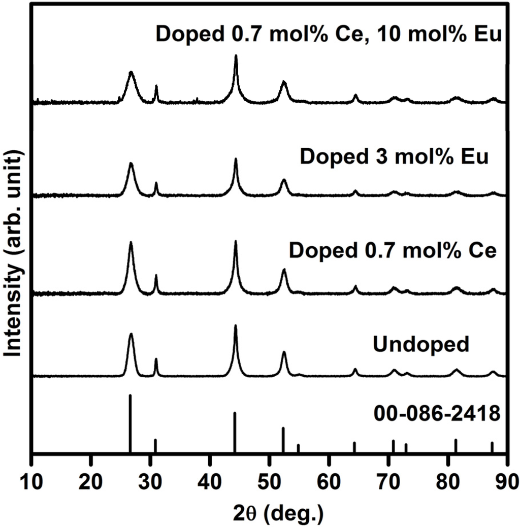
Figure 1.
XRD patterns of pure and doped SrF2.
The estimated average crystallite size (S) for pure and doped SrF2 is calculated by using the diffraction peaks and Scherrer’s equation [15], S = 0.9λ/βcosθ. S is the average crystallite size of the SrF2 particles, λ is the wavelength of the X-rays (0.154 nm) and β is the full-width at half maximum of the X-ray peak at the Bragg angle θ. The average crystallite size of the pure SrF2 was found to be 7.6 nm. The XRD peaks broaden with increasing the dopants ions (see Figure 1). The broadening of the XRD peaks were also observed by other groups [16,17]. H.A.A. Seed Ahmed et al. [16] attributed the XRD peak broadening to impurity broadening. Whereas, F. Wang et al. [17] assigned the XRD peak broadening to reduction in the nanoparticle size of the matrix. In our previous investigation of Eu doped SrF2 samples, we assigned the XRD broadening as a result of a decrease in particle size of the matrix, which agreed well with F. Wang et al. [10]. Therefore, in the current study we can also assign these peaks’ broadening to reduction in particle size of the matrix. The particle size reduced up to 3.9 nm for the SrF2 sample that was doped with 0.7 mol% Ce3+ and 10 mol% Eu.
2.1.2. Auger and TOF SIMS analysis
An Auger profile of Ce and Eu co-doped SrF2 was done to identify the sample’s composition. The Auger spectrum of the SrF2:Ce3+,Eu is presented in Figure 2. The Auger peaks at 71, 1515, 1644 and 1713 eV are assigned to Sr while the F peak is situated at 656 eV [18]. The Auger spectrum not only confirmed the formation of the host matrix, but also showed the presence of the dopants. The Eu peaks were at 111, 142, 853 and 985 eV, while the peak at 89 eV corresponds to Ce. In addition C and O were also observed. The C contamination is attributed to adventitious hydrocarbons and the O is considered to be a common impurity in a fluoride compound [19,20]. The presence of the O in the sample did not change the structure of the sample (see Figure 1). Therefore, the O contamination was due to adventitious impurity species in the surface rather than oxygen impurity in the SrF2 matrix.
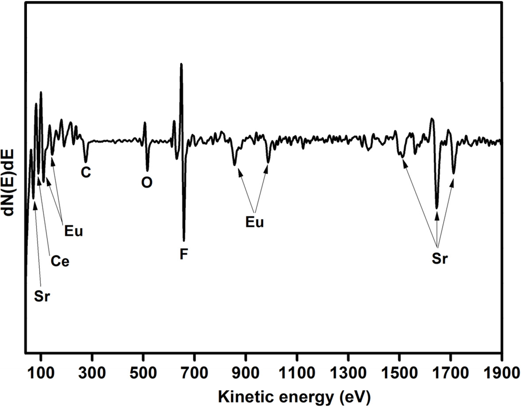
Figure 2.
Auger spectrum of Ce and Eu co-doped SrF2.
It could clearly be seen, not shown, that both the Ce and Eu ions were distributed quite homogeneously over the entire surface area of the Ce and Eu co-doped SrF2. That indicated that the dopants were uniformly distributed in the SrF2 matrix during the hydrothermal synthesis method.
2.1.3. X-ray Photoelectron Spectroscopy (XPS)
XPS measurements have been done in order to investigate the chemical composition and bonding state of the SrF2:Ce,Eu phosphor powders. A higher dopant concentration (5 mol% for both Eu and Ce) was used in order to obtain a reasonable signal from the dopants. Figure 3 shows the peak fits for the (a) Sr 3d, (b) F 1s, (c) Eu 3d and (d) Ce 3d high resolution XPS peaks. The results also confirmed the presence of the host matrix elements (Sr and F) as well as the dopants (Eu and Ce) to their corresponding binding energies. During the peaks fit procedure, the C 1s peak at 284.8 eV was taken as a reference for all charge shift corrections. This is done because the C 1s peak resulted from hydrocarbon contamination and its binding energy generally remains constant, irrespective to the chemical state of the sample. In addition to that, all the Gaussian percentages were assumed to have a combined Gaussian-Lorentzian shape. The high resolution XPS peak for the Sr 3d showed two individual peaks. These two peaks are assigned to Sr 3d in SrF2 that originate from the spin-orbit splitting 3d5/2 (133.5 eV) and 3d3/2 (135.3 eV), while the F 1s peak is situated at 684.7 eV. The spin-orbit splitting of Sr 3d is about 1.78 eV, it is in a good agreement with reported value of 1.75 eV [21].
The peak deconvolution for the Eu 3d high resolution XPS peaks are shown in Figure 3c. The 3d level of Eu ion is composed of four peaks. These four peaks can be attributed to Eu3+ and Eu2+ spin-orbit splitting 3d5/2 and 3d3/2 core level, respectively [21,22,23,24]. The spin-orbit splitting for both oxidation states Eu3+ and Eu2+ is about 29.96 eV. The Eu 3d results showed good agreement with our previous XPS investigation of SrF2:Eu phosphors powder where Eu composed of its two oxidation states (Eu2+ and Eu3+) [10].
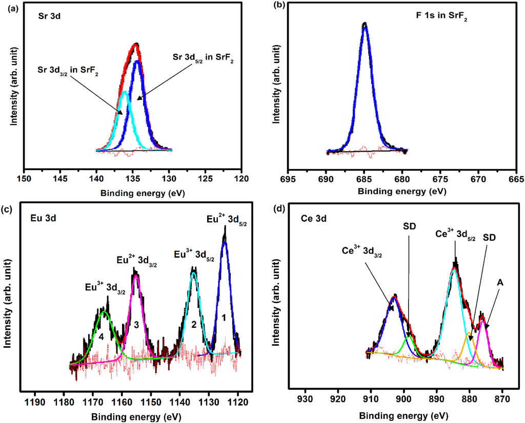
Figure 3.
High resolution XPS peaks of (a) Sr 3d; (b) F 1s; (c) Eu 3d; and (d) Ce 3d for SrF2:Ce,Eu phosphors powder.
The Ce 3d high resolution peak is shown in Figure 3d. The strong peaks correspond to the photoemission from the Ce3+ 3d state. Due to the spin-orbit interaction, the Ce3+ 3d photoemission peak consisted of two peaks that are assigned to the 3d3/2 and 3d5/2 peaks with 4f1 final states, with an intensity ratio I(3d5/2)/I(3d3/2) = 3/2 [22,25,26]. The spin-orbit splitting value (≈18.15 eV) is in good agreement with the estimated value (≈18.10 eV). The energy peaks labelled SD are due to the strong Coulomb interaction between photoemission in the 3d level and electrons located near the Fermi level. These peaks originate from the screening of the 3d level by valence band electrons to the 4f states [22]. This is possible due to hybridization of the Ce 4f level with the conduction band states [26]. In the photoemission nomenclature, these peaks are a result from what is called, shake-down process [22]. The 3d shake-down peaks behave the same as the 3d spin-orbit splitting peaks but they are a result from the 3d9f2 final state. Therefore, the SD peaks can be assigned to the 3d3/2 and 3d5/2 XPS peaks with 4f2 final states and this is in accordance with previous work done in Ce [25,26]. The shoulder peaks marked as A is related to the F KLL Auger electron peak. The XPS peak positions, area distributions and chemical bonding for all the peaks in as-prepared SrF2:Ce,Eu are tabulated in Table 1.

Table 1.
XPS peak position, area distribution and chemical bonding of as-prepared SrF2:Ce,Eu phosphor powder.
| Element | B.E (±0.1 eV) | Area distribution | Interpretation |
|---|---|---|---|
| F1s | 684.7 | 2688 | F in SrF2 |
| Sr3d | 133.5 | 1986 | Sr 3d5/2 in SrF2 |
| 135.3 | 1311 | Sr 3d3/2 in SrF2 | |
| Eu3d | 1123.3 | 1613 | Eu2+ 3d5/2 in fluoride |
| 1133.05 | 1372 | Eu3+ 3d5/2 in fluoride | |
| 1153.2 | 1064 | Eu2+ 3d3/2 in fluoride | |
| Ce3d | 1163.0 | 905 | Eu3+ 3d3/2 in fluoride |
| 880.3 | 1296 | Shake-down satellite | |
| 884.8 | 5141 | Ce3+ 3d5/2 in fluoride | |
| 898.5 | 855 | Shake-down satellite | |
| 903.0 | 3393 | Ce3+ 3d3/2 in fluoride | |
| 876.1 | 1592 | F KL1L1 Auger electron peak |
2.2. Photoluminescence Spectroscopy
2.2.1. SrF2:Ce3+
The emission and excitation spectra of the Ce3+ singly doped SrF2 nanophosphor are shown in Figure 4. The excitation spectrum consists of a prominent peak that is centred at 295 nm. This peak has been previously assigned to Ce3+:4f–5d excitation transition in SrF2 [27]. By exciting the samples by 295 nm, a broad band emission peak is observed, which is attributed to the inter-configuration 5d1−4f1 allowed transition of Ce3+ ions. The inset graph in Figure 4 shows the emission intensity variation as a function of the Ce3+ concentration. The maximum luminescence intensity occurred for the sample doped with 0.7 mol% and a further increase in concentration resulted in a decrease in Ce3+ emission intensity. A previous study done by R. Shendrik et al. [5] on the SrF2:Ce3+ sample reported that Ce3+ has a broad emission band that consist of two emission peaks (Ce3+ 5d to 4f ground state (2F7/2 and 2F5/2)) and the maximum intensity was observed at a Ce3+ dopant concentration of 0.3 mol%. In this study, the peaks were broadened and they fully overlapped, which might be the reason that only one broad peak was observed.
2.2.2. SrF2:Ce,Eu
Figure 5a shows the PL emission spectra of SrF2:Eu obtained by using the He-Cd laser PL system with a 325 nm excitation wavelength. The spectra clearly consist of a broad emission band that is centred at 416 nm with narrow bands in the range of 550–710 nm. The broad emission band is assigned to the inter-configuration 4f65d1–4f7 allowed transition of Eu2+ [11,12] and the narrow emission bands to the Eu3+ emission originating from the 4f–4f transition [28]. The Eu3+ emission consists of orange–red emission bands that is attributed to the 5D0→7FJ transitions (J = 1, 2, 3, 4). This implies that the SrF2:Eu samples consist of both Eu oxidation states (Eu2+ and Eu3+), with their emission ranging from 400 to 710 nm [10]. The Eu3+ emission bands increased with an increase in the Eu dopant concentration in the SrF2 matrix. This can also be seen in Figure 5b, where the emission of Eu3+ excited by 394 nm is portrayed. The PL emission intensity increased slightly at the lower concentrations but then increased dramatically at 10 mol%. The presence of both Eu oxidation states therefore strongly enhanced the emission intensity of the Eu3+ ions. Detailed investigations on the luminescence phenomenon of Eu3+ and Eu2+ have previously been studied by various workers [10,29,30,31].
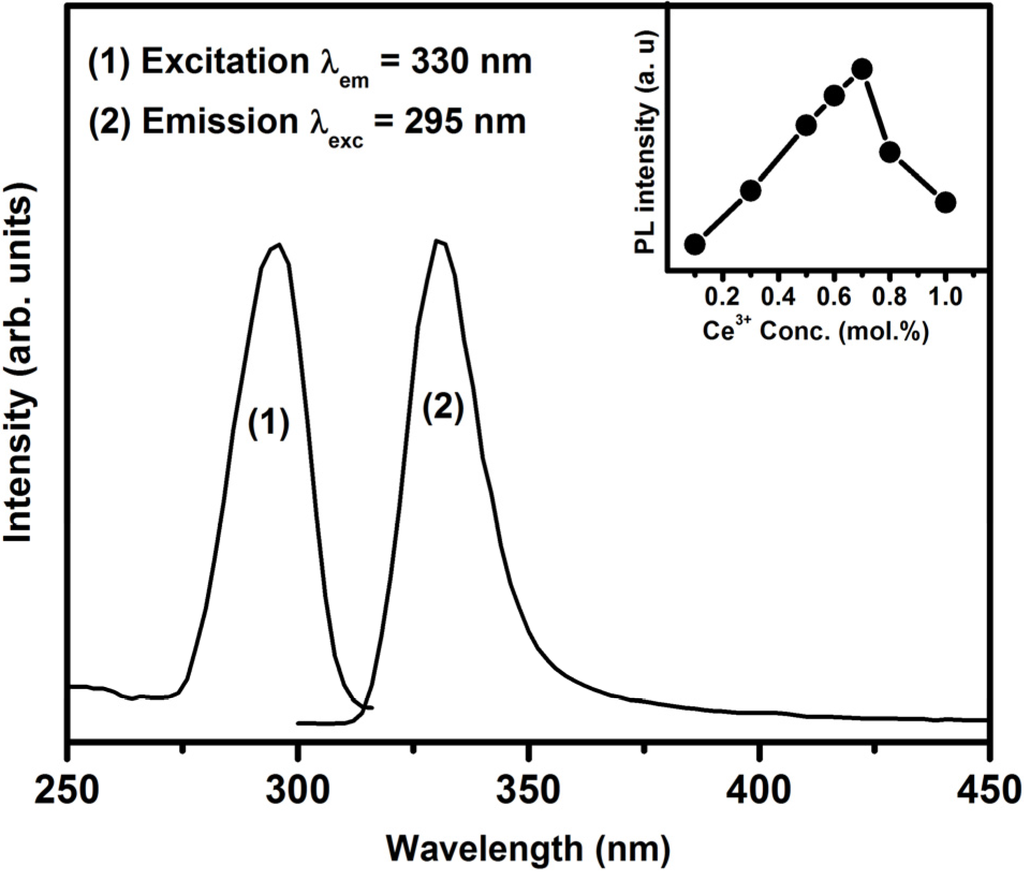
Figure 4.
Excitation and emission spectra of the SrF2:Ce3+ (0.7 mol%) nanophosphor. The inset shows the 5d–4f transition’s emission intensity as a function of Ce3+ concentration.

Figure 5.
Photoluminescence spectra of SrF2:xEu excited by (a) using the He-Cd laser system with 325 nm excitation wavelength and (b) the Cary Eclipse with a wavelength of 394 nm.
Figure 6a depicts the PL emission of Ce3+ (0.7%) co-doped SrF2:xEu (where x = 0.2%, 0.6%, 5% and 10%) excited with the He-Cd laser system with a 325 nm wavelength. The spectra also consisted of both the Eu2+ and Eu3+ emissions. A shoulder peak (marked with a dollar sign ($)) at a lower wavelength only appeared for the smaller dopant concentrations’ (0.2 and 0.6 mol%). This shoulder ($) is assigned to the 4f–5d emission of Ce3+, which is completely quenched at the higher Eu concentration. With an increasing concentration of the Eu ions the relative PL emission intensity of the Eu2+ gradually decreased and the Eu3+ emission intensity increased. The emission intensity of the Eu3+ has dramatically increased at the high Eu doping concentration. This can clearly be seen in Figure 6b where the Eu3+ emission intensity plotted as function of Eu concentration for the Eu co-doped Ce3+ system. It can be noticed that Ce3+ co-doped SrF2:Eu greatly enhanced the Eu3+ ions emission intensity at high Eu concentration. The increase of the Eu3+ emission intensity with an increase in the Eu concentration can be attributed to an increase in the Eu3+/Eu2+ ratio in the presence of the Ce3+ ions. In the SrF2 crystal, the Sr2+ ion is located at the body centre of a cube of eight F− ions. The trivalent Ln3+ ions normally replace the Sr2+ cation. The extra charge of the Ln3+ ions is compensated by F− anion charges situated elsewhere in an interstitial site. With increasing Ln3+ concentration, some kind of structural deformation occurs, the Ln3+-F dipoles couple to dimers, trimers and higher aggregates. The interstitial F- ions and vacancies on the normal F− site compose cuboctahedral clusters [32]. However, at low Eu concentration (less than Ce3+ concentration), the clusters are not completely formed. Besides, compare with the size of the Eu3+ (0.107 nm), the size of the Eu2+ (0.125 nm) is much closer to the size of the Sr2+ (0.126 nm), and hence the reduction of Eu3+ to Eu2+ ions is favored because it could reduce the lattice distortion of the doped SrF2 crystal [33]. At high Eu concentration (bigger than the Ce3+ concentration), the dimensions of the Eu3+ ions cluster increased and hence the ratio of Eu3+/Eu2+ increased. The increase of the Eu3+ ions therefore increased the Eu3+ emission intensity.
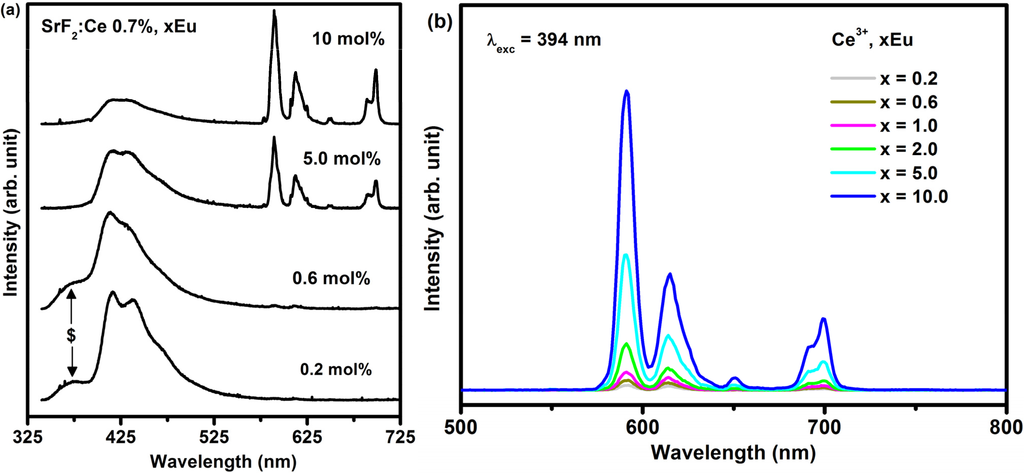
Figure 6.
(a) PL spectra of SrF2:Ce3+ (0.7 mol%), xEu excited with the laser system with a 325 nm excitation wavelength and (b) 394 nm using the xenon lamp.
The PL emission spectra of the SrF2:Ce3+,Eu nanophosphor excited by the 295 nm excitation wavelength are plotted in Figure 7a. The broad emission band that is centered at a wavelength of 330 nm is a characteristic of the Ce3+ ion which is in agreement with the emission spectra for Ce3+ in Figure 4. The additional broad peak beside the Ce3+ emission that was centered at 416 nm is assigned to the Eu2+ ions in SrF2 (clearly shown in the inset graph of Figure 7a). The Eu2+ emission slightly increased before it decreased with increasing Eu concentration. In Figure 7a the emission spectrum of the SrF2:Eu without Ce excited at 295 nm is also shown. It clearly shows no Eu2+ emission has occurred. The presence of Eu2+ emission under 295 nm excitation, in the co-doped samples, is therefore evidence of an energy transfer process from Ce3+ to Eu2+. This process can occur in such material since the emission of Ce3+ overlaps the excitation spectra of Eu2+ (Figure 7b; SrF2:Ce3+ (0.7 mol%), Eu (0.6 mol%)). Such spectral overlap is a necessary condition for the occurrence of the energy transfer from Ce3+ to Eu2+. An efficient energy transfer from Ce3+ to Eu2+ in a fluoride crystal was previously demonstrated even for a very low concentration [34]. More evidence of energy transfer between Ce3+ and Eu2+ is shown in Figure 7c where the room temperature luminescence excitation spectra of SrF2:Ce3+ (0.7 mol%), Eu (0.6 mol%) nanophosphors are plotted. The excitation spectrum of Eu2+ (dotted line) not only consists of the Eu2+:4f7→4f65d excitation transition but also the Ce3+ excitation band (clearly seen in the inset of the Figure 7c). All these results confirm the existence of energy transfer from Ce3+ to the Eu2+ ion.
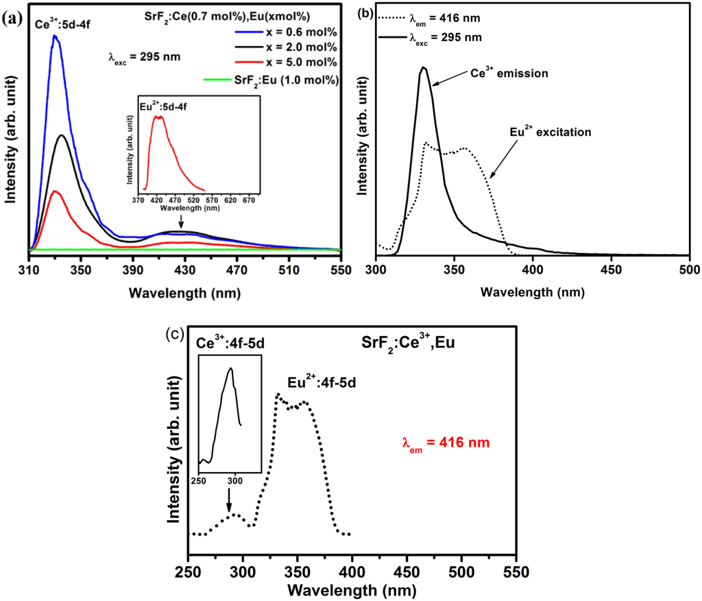
Figure 7.
(a) PL emission spectra of Ce3+ and Eu2+ from SrF2:Ce3+ (0.7 mol%) with different Eu doping concentration as well as from Eu2+ in SrF2:Eu excited by an excitation wavelength of 295 nm; (b) Spectral overlap between Ce3+ emission and Eu2+ excitation and (c) excitation spectra of SrF2:Ce3+ (0.7 mol%), Eu (0.6 mol%) nanophosphors measured at an emission wavelength of 416 nm. The inset in (a) is the enlarge spectrum of the Eu2+emission ions and the inset in (c) is the enlarge Ce3+ excitation from SrF2:Ce3+ (0.7 mol%), Eu (5.0 mol%).
Results obtained from the luminescence decay curves for Ce3+ emission also contributed further to the energy transfer process. The decay time of the donor ions does not change in the presence and absence of the acceptor ions if the radiative energy is dominant [35]. In the situation of non-radiative energy transfer the decay time of the donor ions gradually decreases with an increase in the acceptor concentration. The PL decay curves of Ce3+ with various Eu concentration are shown in Figure 8. The decay curve of the Ce3+ ions gradually decreased with an increase in the Eu concentration. The luminescence decay curve of Ce3+ singly doped SrF2 nanoparticles can well be fitted into a single-exponential function, shown in the inset of Figure 8, whereas the decay curve of the entire co-doped concentrations were fitted with a bi-exponential decay model [35,36]:
I(t) is the luminescence intensity at time t; A1 and A2 are constants; and τ1 and τ2 are the short- and long-decay components, respectively. The average lifetime constant (τ̽ ) can be calculated from the following equation:
I(t) = A1 exp(−t/τ1) + A2 exp(−t/τ2)
τ̽ = (A1 τ12 + A2 τ22)/(A1 τ1 + A2 τ2)
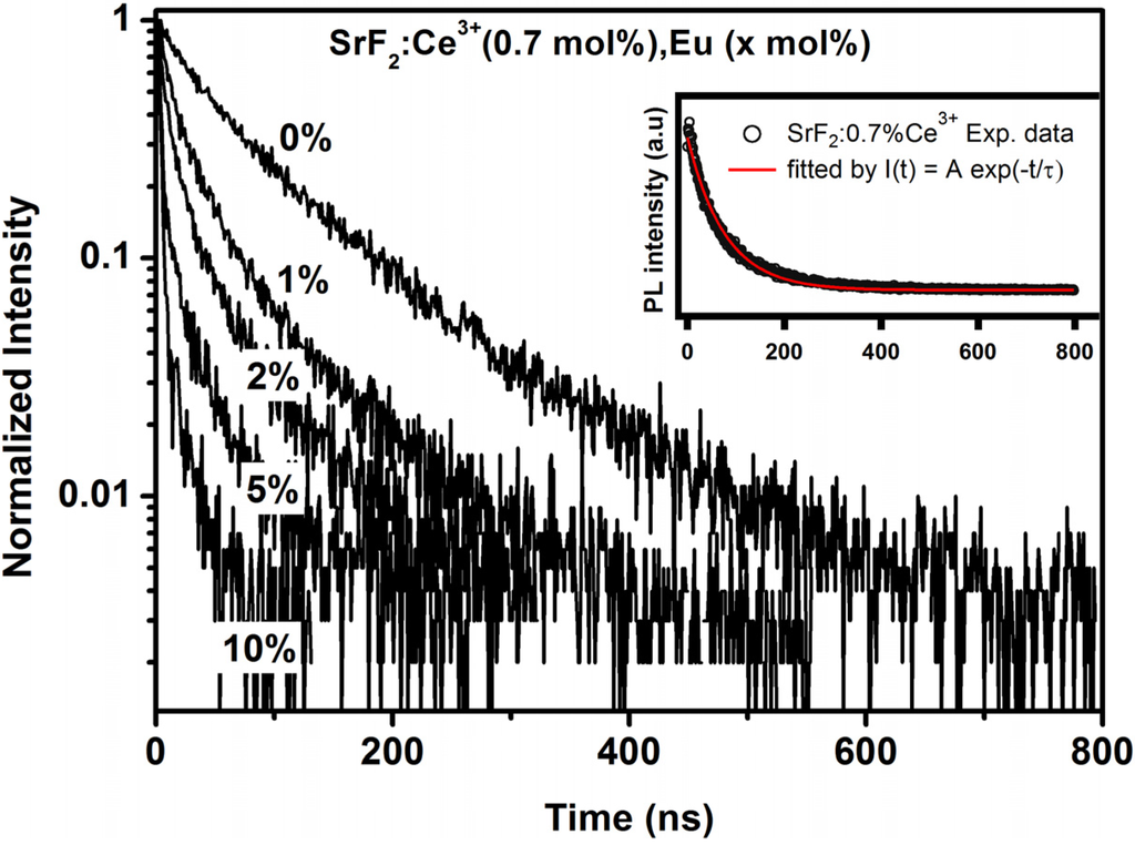
Figure 8.
The decay lifetime of Ce3+ ions in the SrF2 host with an increase in Eu concentration. The inset graph shows the decay curve of 0.7% Ce3+ in SrF2 fitted to a single-exponential fitting function.
The lifetime of the Ce3+ doped SrF2 is determined to be 77.15 ns. This value is in good agreement with the reported value of Ce3+ in SrF2 [27]. In the Eu ions co-doped system, the average lifetime of the donor ion (Ce3+) decreased up to 8.2 ns at 10 mol% Eu concentration. This results confirm that the excitation energy of Ce3+ ions was transferred to the Eu2+ ions. The lifetime results for the Ce3+ ions in the SrF2 host strongly suggest that the energy transfer from Ce3+ to Eu2+ was non-radiative. The energy transfer efficiency from Ce3+ to Eu is defined by the following expression:
where τ and τ0 are the average lifetime of Ce3+ in the presence and absence of the Eu ions, respectively. The corresponding lifetime and energy transfer efficiencies are tabulated in Table 2. From Table 2, the energy transfer of Ce3+ increased gradually with an increase in the Eu concentration. The maximum energy transfer efficiency is about 89.4% for the sample doped with 0.7 mol% Ce3+ and 10 mol% Eu. An efficient energy transfer has occurred from Ce3+ to Eu2+. The emission of Eu2+ has slightly increased before it decreased with increasing Eu concentration due to the decrease of the Eu2+ ratio in the SrF2 host. In our previous investigation of SrF2:Eu the Eu2+ ion was, however, found to be unstable when irradiated by a YAG laser. The Eu2+ ion’s PL emission intensity rapidly decreased with time and this result made the SrF2:Eu nanophosphor an unsuitable candidate for several applications, such as white light-emitting diodes and wavelength conversion films for silicon photovoltaic cells [10].
ɳET = 1− τ/τ0

Table 2.
Lifetime of the 5d–4f transition of Ce3+ (330 nm) and the Ce3+-Eu energy transfer efficiency (ɳET) in SrF2 matrix.
| Eu concentration (mol%) | τ (ns) | ɳET (%) |
|---|---|---|
| 0 | 77.15 | 0 |
| 1 | 46.3 | 40 |
| 2 | 31.9 | 58.6 |
| 5 | 16.05 | 79.2 |
| 10 | 8.2 | 89.4 |
3. Experimental Section
Doped and un-doped SrF2 phosphor samples were synthesised by the hydrothermal method. For the hydrothermal process, all chemical reagents were of analytical grade and were used without further purification. For a typical synthesis, 1 mmol of Sr(NO3)2 was first dissolved in 30 mL distilled water, followed by 5 mmol of C10H14N2O8.2H2O (Na2EDTA, ethylenediamine tetraacetic acid disodium salt) and 2 mmol of NaBF4 under constant stirring. After further magnetic stirring for 10 min the solution was transferred into a 125 mL autoclave lined with Teflon, heated at 160 °C for one hour and naturally cooled down to room temperature [37]. The product was collected by centrifugal and washed with water and ethanol. Finally, the product was dried for 10 h in an oven at 60 °C. Ce3+ and Eu co-doped SrF2 samples were prepared by the same hydrothermal technique. Eu(NO3)3(H2O)5 and Ce(NO3)3(H2O)6 were used as sources for the Eu and Ce dopants, respectively.
The phosphors were characterized by X-ray diffraction (XRD) (Bruker AXS Gmbh, Karlsruhe, Germany) (Bruker Advance D8 diffractometer with Cu Kα radiation (λ = 0.154 nm)) to identify the crystalline structure of the powder. Auger spectra were collected with a PHI 700 Scanning Auger Nanoprobe (ULVAC-PHI Inc, Chanhassan, MN, USA) equipped with a scanning Auger microscope (SAM). The field emission electron gun used for the SAM analyses was set at: 2.34 A filament current; 4.35 kV extractor voltage and 381.4 µA extractor current. With these settings a 25 kV, 10 nA electron beam was obtained for the Auger analyses. The electron beam diameter was about 10 nm. An IonTof time of flight secondary ion mass spectrometer (TOF-SIMS) instrument (ION-TOF Gmbh, Muenster, Germany) equipped with a Bi primary ion source was used to characterize the nanophosphor materials for their chemical composition and dopants distribution. In spectroscopy mode, the system equipped with a DC current of 30 nA and a pulsed current of 1 pA at 30 kV with a heating current of 2.95 A and emission current of 0.8 μA was used. High resolution X-ray photoelectron spectroscopy (XPS) was obtained with a PHI 5000 Versaprobe system (ULVAC-PHI Inc, Chanhassan, MN, USA). A low energy Ar+ ion gun and low energy neutralizer electron gun were used to minimize charging on the surface. A 100 μm diameter monochromatic Al Kα X-ray beam (hν = 1486.6 eV) generated by a 25 W, 15 kV electron beam was used to analyze the different binding energy peaks. The pass energy was set to 11 eV giving an analyzer resolution ≤0.5 eV. Multipack version 8.2 software (ULVAC-PHI Inc, Chanhassan, MN, USA) was utilized to analyze the spectra to identify the chemical compounds and their electronic states using Gaussian-Lorentz fits. Photoluminescence spectra (PL) were collected using a Cary Eclipse fluorescence spectrophotometer (Varian Ltd, Mulgrave Victoria, Australia) equipped with a xenon lamp and also with a He-Cd laser PL system with a 325 nm excitation wavelength. Luminescence decay curves were recorded by using a NanoLED with a 335 nm excitation wavelength and repetition rate of 1 MHz. All measurements were performed at room temperature.
4. Conclusions
As-prepared SrF2:Eu,Ce nanophosphors were successfully synthesised with the hydrothermal technique. The average crystallite size that was calculated by using Scherrer’s equation was found to be 7.6 nm for the host sample. Dopant ions were intended to decrease the particle size of the host. The Auger spectra confirmed the presence of Sr, F, Eu and Ce elements in the host matrix. Photoluminescence properties of Ce3+ and Eu co-doped SrF2 nano-phosphor have been investigated. A possible efficient energy transfer from Ce3+ to Eu2+ ions was demonstrated. From the PL decay curves the energy transfer efficiency was calculated to be 89.4% for the SrF2: 0.7 mol% Ce3+, 10 mol% Eu sample.
Acknowledgments
This work is based on the research supported by the South African Research Chairs Initiative of the Department of Science and Technology and National Research Foundation of South Africa. The financial assistance of the National Research Foundation (NRF) and the University of the Free State towards this research is hereby acknowledged.
Author Contributions
Hendrik C. Swart is the leader of the research group and supervisor of the PhD students and he helped with the data interpretation and writing of the paper. Elizabeth Coetsee is also one of the supervisors of the PhD students and she helped with the editing of the paper. Luyanda Noto helped with the TOF-SIMS analysis and discussion and Mubarak Y. A. Yagoub was mainly responsible for the planning, experimental part as well as writing the main part of the paper, the decay measurements were done with the help of Peber Bergman in his laboratory.
Conflicts of Interest
The authors declare no conflict of interest.
References
- Ivanovskikh, K.V.; Pustovarov, V.A.; Krim, M.; Shulgin, B.V. Time-resolved vacuum ultraviolet spectroscopy of Er3+ ions in the SrF2 crystal. J. Appl. Spectrosc. 2005, 72, 564–568. [Google Scholar] [CrossRef]
- Van der Ende, B.M.; Aarts, L.; Meijerink, A. Near-infrared quantum cutting for photovoltaics. Adv. Mater. 2009, 21, 3073–3077. [Google Scholar]
- Ivanovskikh, K.; Pustovarov, V.; Smirnov, A.; Shulgin, B. Inter- and intraconfigurational luminescence of trivalent rare earth ions doped into strontium fluoride crystals under vacuum ultraviolet excitation. Phys. Stat. Solidi C 2007, 4, 889–892. [Google Scholar] [CrossRef]
- Kristianpoller, N.; Weiss, D.; Chen, R. Optical and dosimetric properties of variously doped SrF2 crystals. Radiat. Meas. 2004, 38, 719–722. [Google Scholar] [CrossRef]
- Shendrik, R.; Radzhabov, E.A.; Nepomnyashchikh, A.I. Scintillation properties of pure and Ce3+-doped SrF2 crystals. Radiat. Meas. 2013, 56, 58–61. [Google Scholar] [CrossRef]
- Shendrik, R.; Radzhabov, E. Emission in CaF2, BaF2, SrF2. IEEE Trans. Nucl. Sci. 2009, 57, 1295–1299. [Google Scholar] [CrossRef]
- Gao, D.; Zheng, H.; Zhang, X.; Fu, Z.; Zhang, Z.; Tian, Y.; Cui, M. Efficient fluorescence emission and photon conversion of LaOF:Eu3+ nanocrystals. Appl. Phys. Lett. 2011, 98, 011907–011909. [Google Scholar] [CrossRef]
- Chung, P.; Chung, H.; Holloway, P.H. Phosphor coatings to enhance Si photovoltaic cell performance. J. Vac. Sci. Technol. A 2007, 25, 61–66. [Google Scholar] [CrossRef]
- Huang, X.Y.; Wang, J.X.; Yu, D.C.; Ye, S.; Zhang, Q.Y.; Sun, X.W. Spectral conversion for solar cell efficiency enhancement using YVO4:Bi3+,Ln3+ (Ln = Dy, Er, Ho, Eu, Sm, and Yb) phosphors. J. Appl. Phys. 2011, 109, 113526–113532. [Google Scholar] [CrossRef]
- Yagoub, M.Y.A.; Swart, H.C.; Noto, L.L.; O’Connell, J.H.; Lee, M.E.; Coetsee, E. The effects of Eu-concentrations on the luminescent properties of SrF2:Eu nanophosphor. J. Lumin. 2014, 156, 150–156. [Google Scholar] [CrossRef]
- Li, Y.C.; Chang, Y.H.; Lin, Y.F.; Chang, Y.S.; Lin, Y.J. Synthesis and luminescent properties of Ln3+ (Eu3+, Sm3+, Dy3+)-doped lanthanum aluminum germanate LaAlGe2O7 phosphors. J. Alloys Compd. 2007, 439, 367–375. [Google Scholar] [CrossRef]
- Jin, Y.; Qin, W.; Zhang, J. Preparation and optical properties of SrF2: Eu3+ nanospheres. J. Fluor. Chem. 2008, 129, 515–518. [Google Scholar] [CrossRef]
- Huang, X.; Han, S.; Huang, W.; Liu, X. Enhancing solar cell efficiency: The search for luminescent materials as spectral converters. Chem. Soc. Rev. 2013, 42, 173–201. [Google Scholar] [CrossRef] [PubMed]
- Rakov, N.; Guimaraes, R.B.; Franceschini, D.F.; Maciel, G.S. Er:SrF2 luminescent powders prepared by combustion synthesis. Mater. Chem. Phys. 2012, 135, 317–321. [Google Scholar] [CrossRef]
- Oprea, C.; Ciupina, V.; Prodan, G. Investigation of nanocrystals using TEM micrographs and electron diffraction technique. Rom. J. Phys. 2008, 53, 223–230. [Google Scholar]
- Seed Ahmed, H.A.A.; Ntwaeaborwa, O.M.; Kroon, R.E. The energy transfer mechanism in Ce,Tb co-doped LaF3 nanoparticles. Curr. Appl. Phys. 2013, 13, 1264–1268. [Google Scholar] [CrossRef]
- Wang, F.; Han, Y.; Lim, C.S.; Lu, Y.; Wang, J.; Xu, J.; Chen, H.; Zhang, C.; Hong, M.; Liu, X. Simultaneous phase and size control of upconversion nanocrystals through lanthanide doping. Nature 2010, 463, 1061–1065. [Google Scholar] [CrossRef] [PubMed]
- Childs, K.D.; Carlson, B.A.; LaVanier, L.A.; Moulder, J.F.; Paul, D.F.; Stickle, W.F.; Watson, D.G. Handbook of Auger Electron Spectroscopy, 3rd ed.; Physical Electronics: Eden Peairie, MN, USA, 1995. [Google Scholar]
- Kroon, R.E.; Swart, H.C.; Ntwaeaborwa, O.M.; Seed Ahmed, H.A.A. Ce decay curves in Ce, Tb co-doped LaF3 and the energy transfer mechanism. Phys. B 2014, 439, 83–87. [Google Scholar] [CrossRef]
- Van Wijngaarden, J.T.; Scheidelaar, S.; Vlugt, T.J.H.; Reid, M.F.; Meijerink, A. Energy transfer mechanism for downconversion in the (Pr3+, Yb3+) couple. Phys. Rev. B 2010, 81, 155112–155117. [Google Scholar] [CrossRef]
- Vasquez, R.P. SrF2 by XPS. Surf. Sci. Spectr. 1992, 1, 24–30. [Google Scholar] [CrossRef]
- Vercaemst, R.; Poelman, D.; van Meirhaeghe, R.L.; Fiermans, L.; Laflere, W.H.; Cardon, F. An XPS study of the dopants’ valence states and the composition of CaS1–xSex:Eu and SrS1–xSex:Ce thin film electroluminescent devices. J. Lumin. 1995, 63, 19–30. [Google Scholar] [CrossRef]
- Lu, D.; Sugano, M.; Sun, X.Y.; Su, W. X-ray photoelectron spectroscopy study on Ba1−xEuxTiO3. Appl. Surf. Sci. 2005, 242, 318–325. [Google Scholar] [CrossRef]
- Zhang, J.; Yang, M.; Jin, H.; Wang, X.; Zhao, X.; Liu, X.; Peng, L. Self-assembly of LaBO3:Eu twin microspheres synthesized by a facile hydrothermal process and their tunable luminescence properties. Mater. Res. Bull. 2012, 47, 247–252. [Google Scholar] [CrossRef]
- Lässer, R.; Fuggle, J.C.; Beyss, M.; Campagna, M. X-ray photoemission from Ce core levels of CePd3, CeSe, CeAl2 and CeCu2Si2. Phys. B C 1980, 102, 360–366. [Google Scholar] [CrossRef]
- Gamza, M.; Slebarski, A.; Rosner, H. Electronic structure of Ce5Rh4Sn10 from XPS and band structure calculations. Eur. Phys. J. B 2008, 63, 1–9. [Google Scholar] [CrossRef]
- Zhang, C.; Hou, Z.; Chai, R.; Cheng, Z.; Xu, Z.; Li, C.; Huang, L.; Lin, J. Mesoporous SrF2 and SrF2:Ln3+ (Ln = Ce, Tb, Yb, Er) Hierarchical microspheres: Hydrothermal synthesis, growing mechanism, and luminescent properties. J. Phys. Chem. C 2010, 114, 6928–6936. [Google Scholar] [CrossRef]
- Dorenbos, P. Energy of the first 4f7 → 4f65d transition of Eu2+ in inorganic compounds. J. Lumin. 2003, 104, 239–260. [Google Scholar] [CrossRef]
- Dorenbos, P. Valence stability of lanthanide ions in inorganic compounds. Chem. Mater. 2005, 17, 6452–6456. [Google Scholar] [CrossRef]
- Baran, A.; Barzowska, J.; Grinberg, M.; Mahlik, S.; Szczodrwksi, K.; Zorenko, Y. Binding energy of Eu2+ and Eu3+ ions in β-Ca2SiO4 doped with europium. Opt. Mater. 2013, 35, 2017–2114. [Google Scholar] [CrossRef]
- Biswas, K.; Sontakke, A.D.; Sen, R.; Annapurna, K. Luminescence properties of dual valence Eu doped nano-crystalline BaF2 embedded glass-ceramics and observation of Eu2+→Eu3+ energy transfer. J. Fluoresc. 2012, 22, 745–752. [Google Scholar] [CrossRef] [PubMed]
- Pandey, C.; Dhopte, S.M.; Muthal, P.L.; Kondawar, V.K.; Moharil, S.V. Eu3+↔Eu2+ redox reactions in bulk and nano CaF2:Eu. Radiat. Eff. Defects Solids 2007, 162, 651–658. [Google Scholar] [CrossRef]
- Wang, X.; Wu, N.; Shimizu, M.; Sakakura, M.; Shimotsuma, Y.; Miura, K.; Zhou, S.; Qiu, J.; Hirao, K. Space selective reduction of europium ions via SrF2 crystals induced by high repetition rate femtosecond laser. J. Ceram. Soc. Jpn. 2011, 119, 939–941. [Google Scholar] [CrossRef]
- Caldino, U.G.; Gruz, C.D.; Monoz, G.H.; Rubio, J.O. Ce3+→Eu2+ energy transfer in CaF2. Solid State Commun. 1989, 4, 347–351. [Google Scholar] [CrossRef]
- Zhou, J.; Xia, Z.; You, H.; Shen, K.; Yang, M.; Liao, L. Synthesis and tunable luminescence properties of Eu2+ and Tb3+-activated Na2Ca4(PO4)3F phosphors based on energy. J. Lumin. 2013, 135, 20–25. [Google Scholar] [CrossRef]
- Katsumata, T.; Nabae, T.; Sasajima, K.; Komuro, S.; Morikawa, T. Effects of composition on the long phosphorescent SrAl2O4 : Eu2 +, Dy3 + Phosphor Crystals. J. Electrochem. Soc. 1997, 144, L243–L245. [Google Scholar] [CrossRef]
- Peng, J.; Hou, S.; Liu, X.; Feng, J.; Yu, X.; Xing, Y.; Su, Z. Hydrothermal synthesis and luminescence properties of hierarchical SrF2 and SrF2:Ln3+ (Ln = Er, Nd, Yb, Eu, Tb) micro/nanocomposite architectures. Mater. Res. Bull. 2012, 47, 328–332. [Google Scholar] [CrossRef]
© 2015 by the authors; licensee MDPI, Basel, Switzerland. This article is an open access article distributed under the terms and conditions of the Creative Commons Attribution license (http://creativecommons.org/licenses/by/4.0/).