
Endurance of Damping Properties of Foam-Filled Tubes

Abstract
:1. Introduction
1.1. Stability of Damping Properties of Cellular Metals
1.2. Stability of Damping Properties of Foam-Filled Structures
2. Damping Stability of Foam-Filled Tubes

2.1. Production and Properties of the Foam-Filled Tubes

| Materials | Properties | |
|---|---|---|
| Outer case: steel tubular elements | Yield stress 250 MPa, length 500 mm, square cross-section 50 mm × 50 mm, 2 mm wall thickness | |
 | Filling: APM L | Low-density hybrid foam (estimated ρ ~ 490 kg/m3), made by hybrid aluminum-epoxy foam |
| Filling: APM H | High-density hybrid foam (estimated ρ ~ 590 kg/m3), made by hybrid aluminum-epoxy foam | |
 | Filling: AlSi10 | Alulight Foaminal AlSi10 foam (estimated ρ ~ 550 kg/m3) |
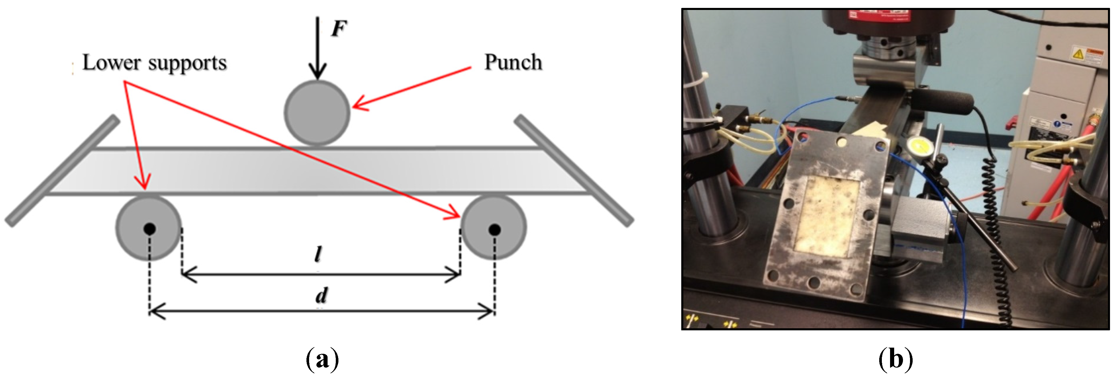
2.2. Cyclic Three-Point Bending Tests

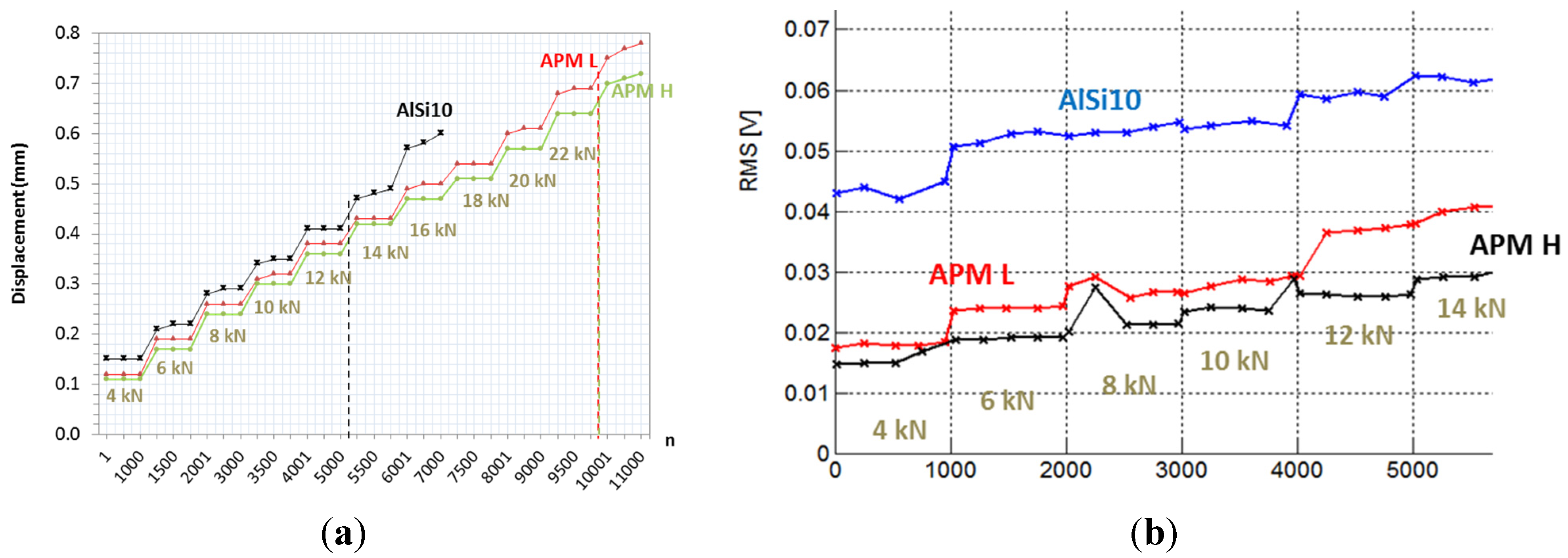
2.2.1. Preliminary Tests

2.2.2. Final Tests
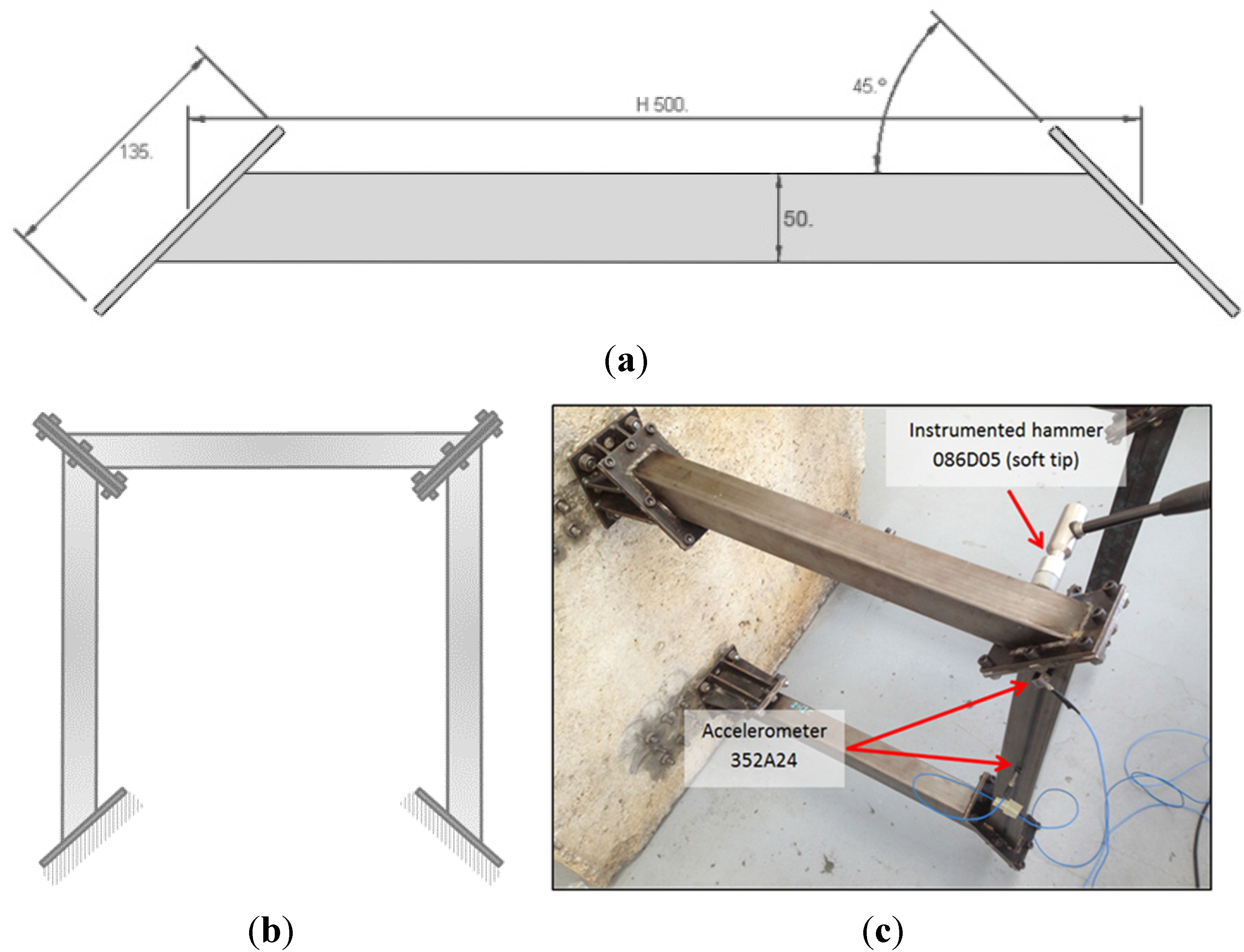
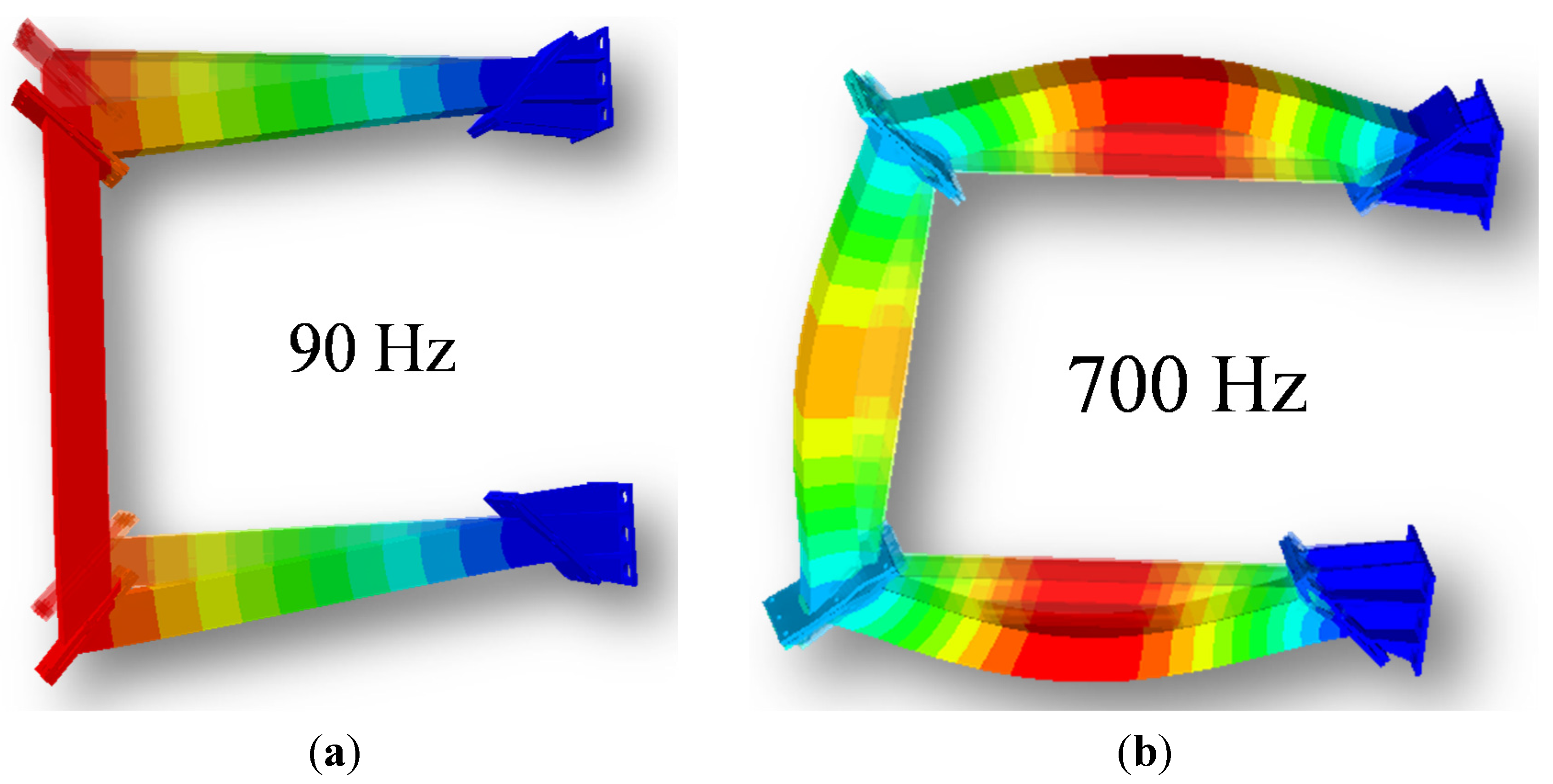
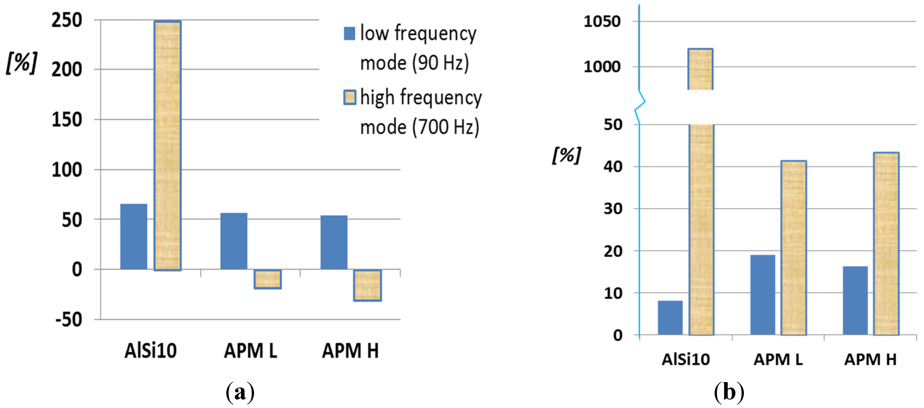
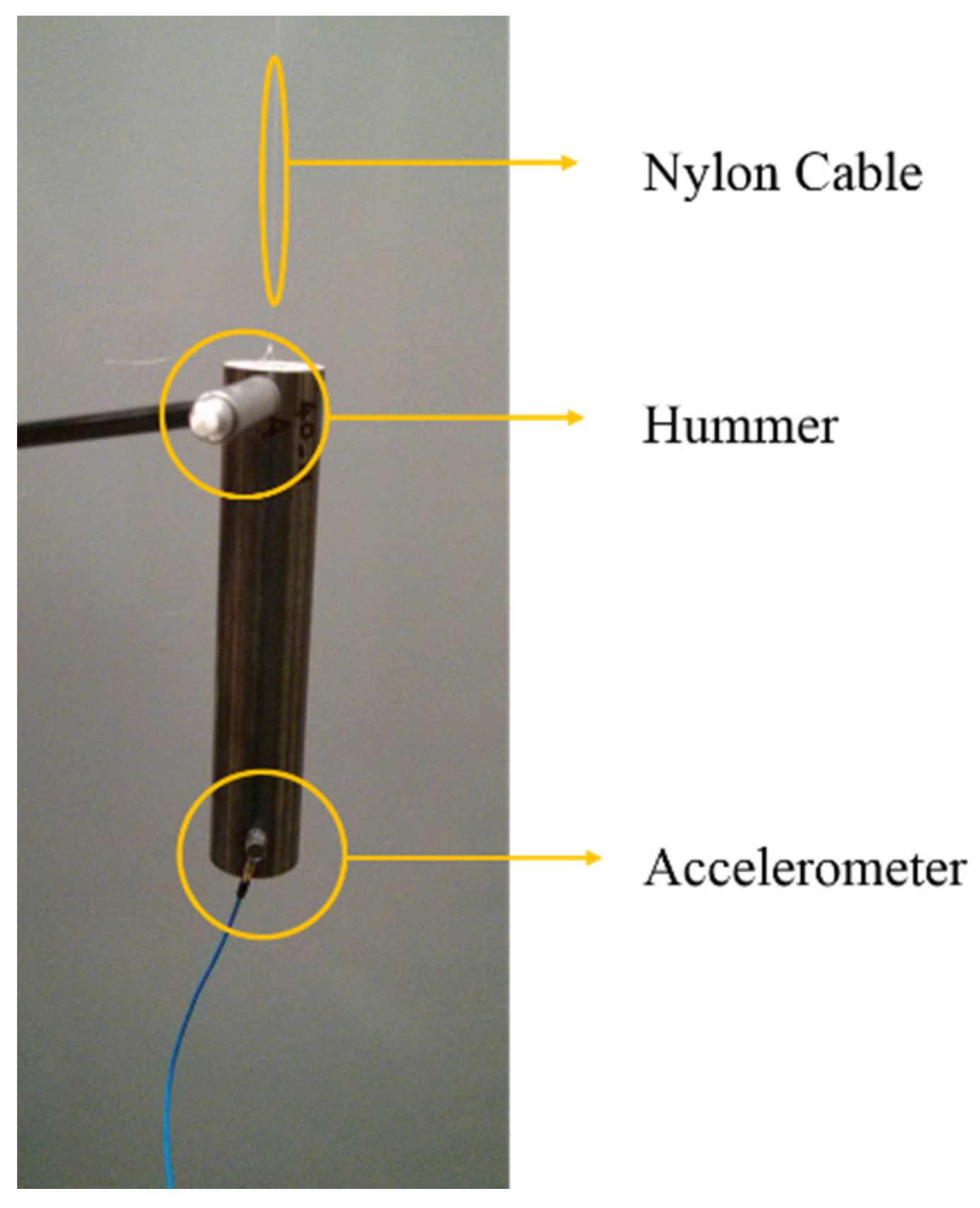
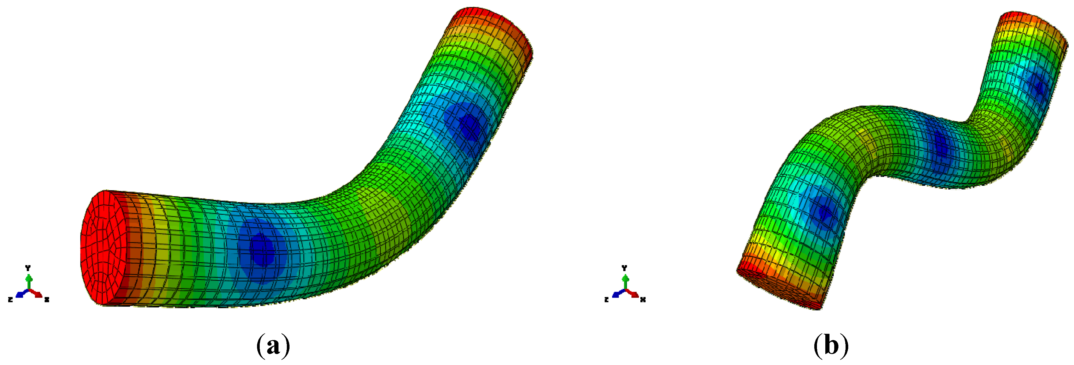
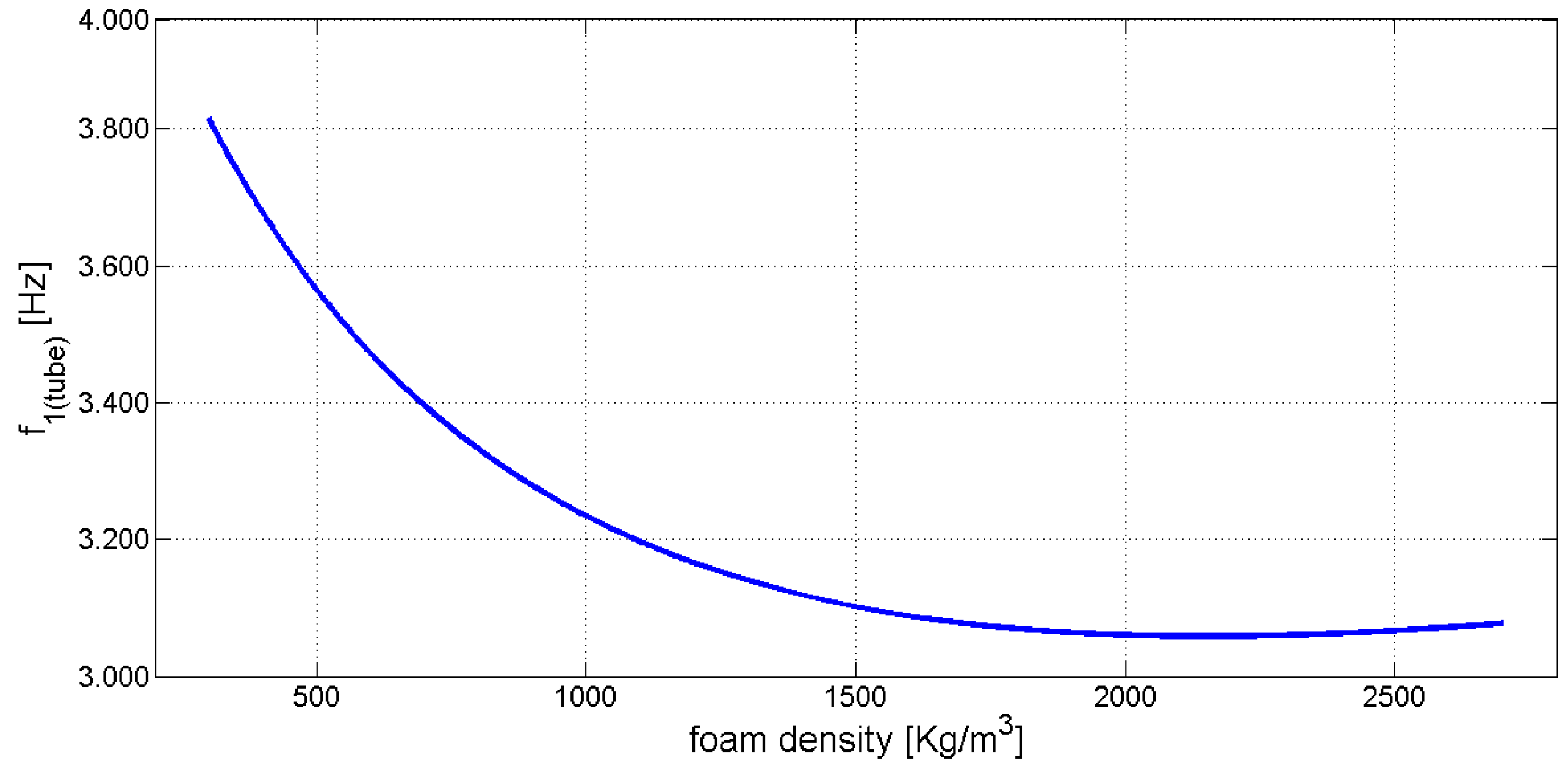
2.3. Modal Analysis


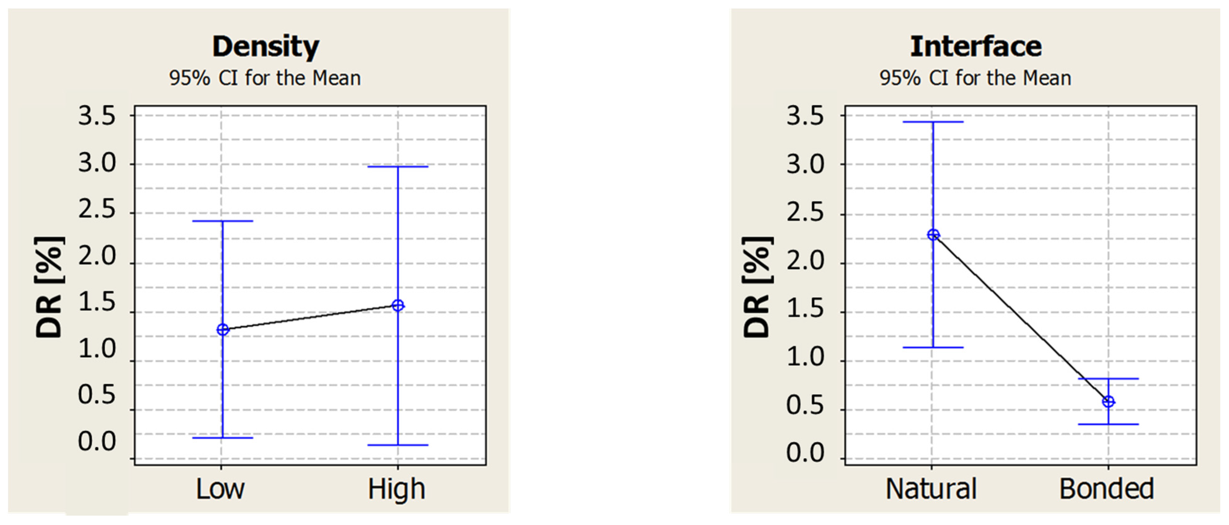
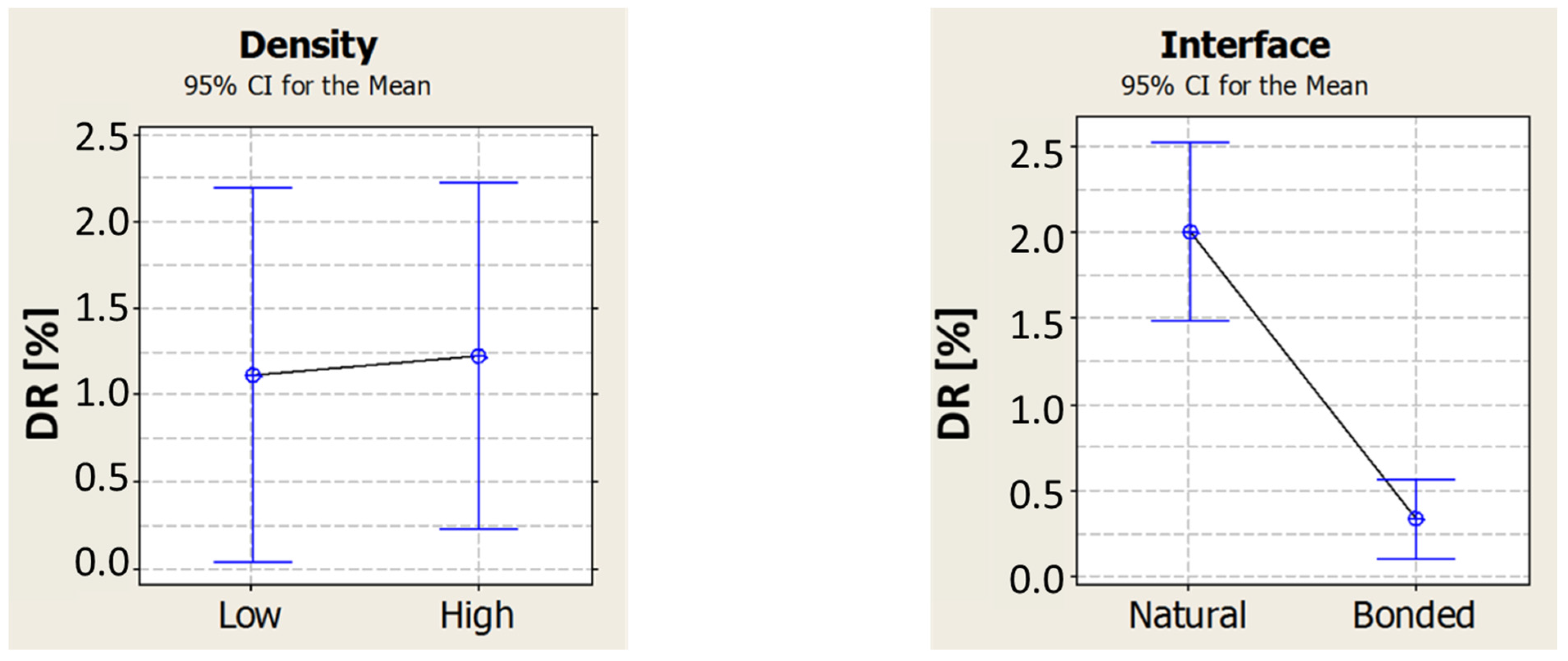
3. The Interface Effect
3.1. Test Materials
3.2. The Influence on Damping
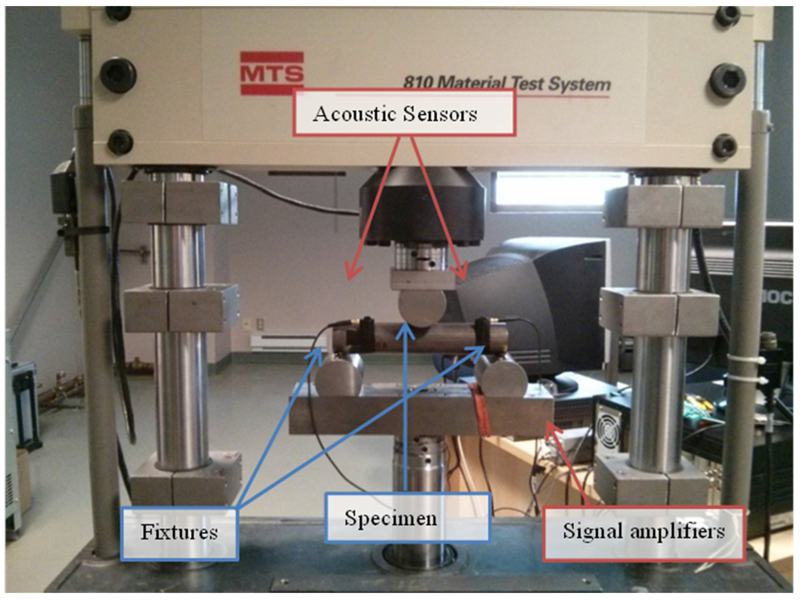
3.2.1. Methods

3.2.2. Results


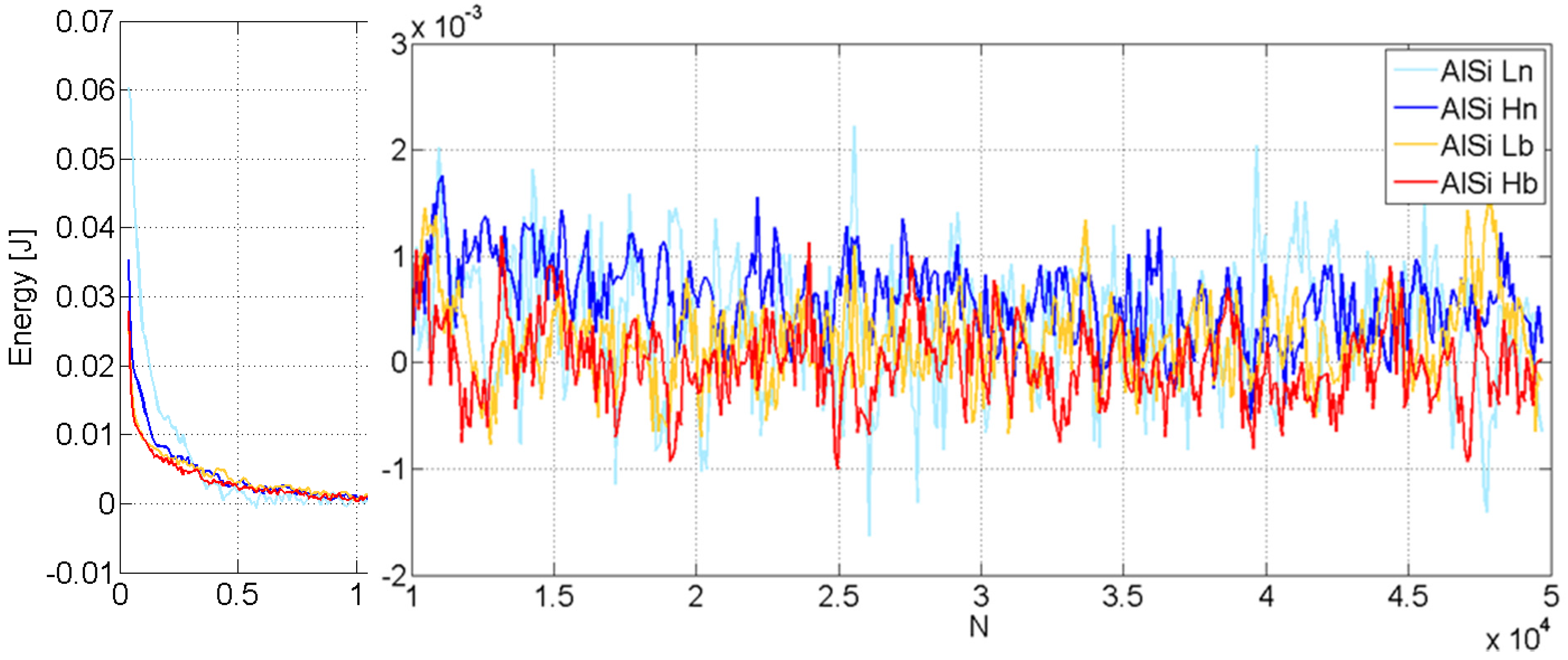
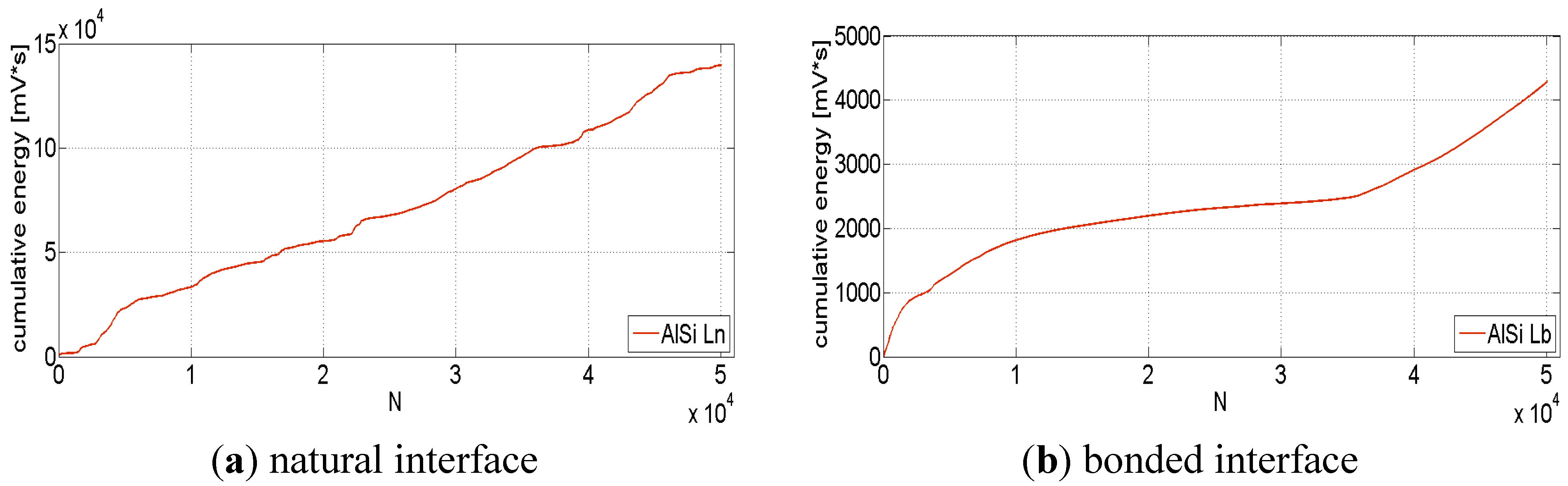
3.3. Cyclic Three-Point Bending Tests

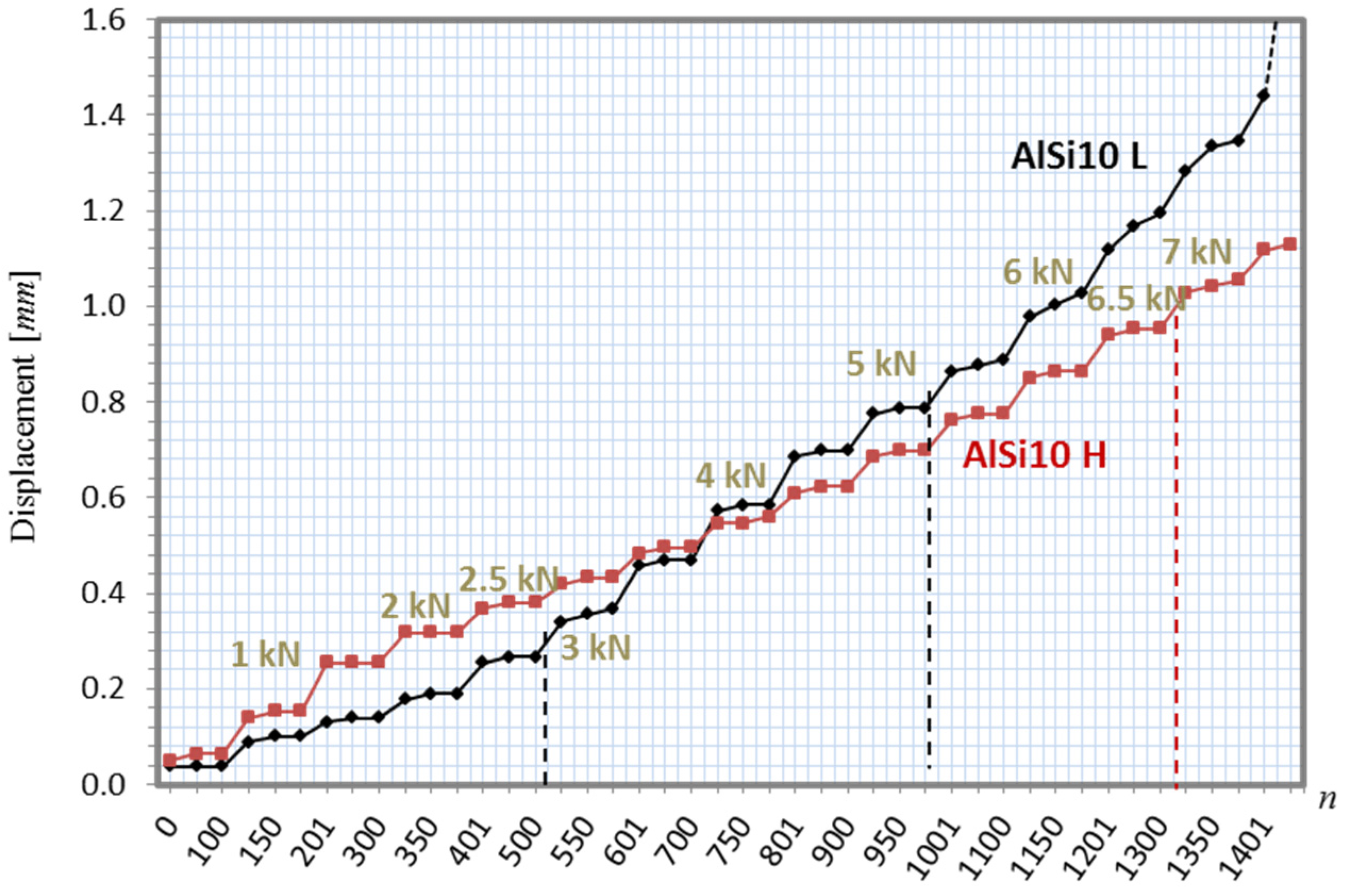
3.3.1. Step Loading Preliminary Tests

3.3.2. Constant Loading Test
| Specimen | dmax (first cycle) | dmax (last cycle) | Δdmax% |
|---|---|---|---|
| AlSi Ln | 0.4065 | 0.4507 | +10.9% |
| AlSi Hn | 0.3321 | 0.3877 | +16.7% |
| AlSi Lb | 0.2404 | 0.2728 | +13.5% |
| AlSi Hb | 0.1856 | 0.2134 | +15.0% |


4. Conclusions
Acknowledgments
Author Contributions
Conflicts of Interest
References
- Banhart, J.; Baumeister, J. Deformation characteristics of metal foams. J. Mater. Sci. 1998, 33, 1431–1440. [Google Scholar] [CrossRef]
- Banhart, J. Manufacture, Characterisation and application of cellular metals and metal foams. Prog. Mater. Sci. 2001, 46, 559–632. [Google Scholar] [CrossRef]
- Evans, A.G.; Hutchinson, J.W.; Ashby, M.F. Multifunctionality of cellular metal systems. Prog. Mater. Sci. 1999, 43, 171–221. [Google Scholar] [CrossRef]
- Baumeister, J.; Weise, J.; Hirtz, E.; Höhne, K.; Hohe, J. Applications of aluminum hybrid foam sandwiches in battery housings for electric vehicles. Materialwissenschaft. Und. Werkstofftechnik. 2014, 45, 1099–1107. [Google Scholar] [CrossRef]
- Weise, J.; Ruparelia, D.; Wichmann, M.; Baumeister, J. Investigation of the mechanical behaviour of particulate aluminum epoxy hybride foams in dependence upon metal and polymer conten. In International Conference on Cellular Materials, CellMat; Deutsche Gesellschaft für Materialkunde e.V.: Dresden, Germany, 2010. [Google Scholar]
- Baumeister, J.; Monno, M.; Goletti, M.; Mussi, V.; Weise, J. Dynamic behavior of hybrid APM (advanced pore morphology foam) and aluminum foam filled structures. Metals 2012, 2, 211–218. [Google Scholar] [CrossRef] [Green Version]
- Neugebauer, R.; Hipke, T. Machine Tools with Metal Foams. Adv. Eng. Mater. 2006, 8, 858–863. [Google Scholar] [CrossRef]
- Koza, E.; Leonowicz, M.; Wojciechowski, S.; Simancik, F. Compressive strength of aluminum foams. Mater. Lett. 2003, 58, 132–135. [Google Scholar] [CrossRef]
- Banhart, J.; Baumeister, J.; Weber, M. Damping properties of aluminum foams. Mater. Sci. Eng. A 1996, 205, 221–228. [Google Scholar] [CrossRef]
- Lehmhus, D.; Marschner, C.; Banhart, J.; Bomas, H. Influence of heat treatment on compression fatigue of aluminum foams. J. Mater. Sci. 2002, 37, 3447–3451. [Google Scholar] [CrossRef]
- Zettl, B.; Mayer, H. Fatigue properties of Al-1Mg-0.6Si foam at low and ultrasonic frequencies. Int. J. Fatigue 2001, 23, 565–573. [Google Scholar] [CrossRef]
- Golovin, I.S.; Sinning, H.-R.; Goken, J.; Riehemann, W. Fatigue-related damping in some cellular metallic materials. Mater. Sci. Eng. A 2004, 370, 537–541. [Google Scholar] [CrossRef]
- Golovin, I.; Sinning, H.-R. Internal friction in metallic foams and some related cellular structures. Mater. Sci. Eng. A 2004, 370, 504–511. [Google Scholar] [CrossRef]
- Dattoma, V.; Giannoccaro, N.I.; Messina, A.; Nobile, R. Fatigue damage evaluation of metallic foam specimens through modal data. In Proceedings of the 2008 SEM XI International Congress & Exposition on Experimental & Applied Mechanics, Orlando, FL, USA, 2–5 June 2008.
- Dattoma, V.; Giannoccaro, N.I.; Messina, A.; Nobile, R. Prediction of residual fatigue life of aluminum foam through natural frequencies and damping shift. Fatigue Fract. Eng. Mater. Struct. 2009, 32, 601–616. [Google Scholar] [CrossRef]
- Zarei, H.R.; Kroger, M. Optimization of the foam-filled aluminum tubes for crush box application. Thin Wall. Struct. 2008, 46, 214–221. [Google Scholar] [CrossRef]
- Duarte, I.; Vesenjak, M.; Krstulović-Opara, L. Dynamic and quasi-static bending behaviour of thin-walled aluminum tubes filled with aluminum foam. Compos. Struct. 2014, 109, 48–56. [Google Scholar] [CrossRef]
- Kolluri, M.; Mukherjee, M.; Garcia-Moreno, F.; Banhart, J.; Ramamurty, U. Fatigue of a laterally constrained closed cell aluminum foam. Acta Mater. 2008, 56, 1114–1125. [Google Scholar] [CrossRef]
- Harte, A.; Fleck, N.A.; Ashby, M.F. The fatigue strength of sandwich beams with an aluminum alloy foam core. Int. J. Fatigue 2001, 23, 499–507. [Google Scholar] [CrossRef]
- Edwins, D.J. Modal Testing: Theory, Practice and Application, 2000; Research Studies Press: Hertfordshire, UK, 2000. [Google Scholar]
- Yan, M.; Fan, Z. Durability of materials in molten aluminum alloys. J. Mater. Sci. 2001, 36, 285–295. [Google Scholar] [CrossRef]
- Ashby, M.F.; Evans, A.G.; Fleck, N.A.; Gibson, L.J.; Hutchinson, J.W.; Wadley, H.N.G. Metal Foams: A Design Guide; Butterworth-Heinemann: Oxford, UK, 2000. [Google Scholar]
- Barsoum, F.F.; Suleman, J.; Korcak, A.; Hil, E.V.K. Acoustic emission monitoring and fatigue life prediction in axially loaded notched steel specimens. J. Acoust. Emiss. 2009, 29, 40–63. [Google Scholar]
© 2015 by the authors; licensee MDPI, Basel, Switzerland. This article is an open access article distributed under the terms and conditions of the Creative Commons Attribution license (http://creativecommons.org/licenses/by/4.0/).
Share and Cite
Strano, M.; Marra, A.; Mussi, V.; Goletti, M.; Bocher, P. Endurance of Damping Properties of Foam-Filled Tubes. Materials 2015, 8, 4061-4079. https://doi.org/10.3390/ma8074061
Strano M, Marra A, Mussi V, Goletti M, Bocher P. Endurance of Damping Properties of Foam-Filled Tubes. Materials. 2015; 8(7):4061-4079. https://doi.org/10.3390/ma8074061
Chicago/Turabian StyleStrano, Matteo, Alessandro Marra, Valerio Mussi, Massimo Goletti, and Philippe Bocher. 2015. "Endurance of Damping Properties of Foam-Filled Tubes" Materials 8, no. 7: 4061-4079. https://doi.org/10.3390/ma8074061