Article

Post Processing and Biological Evaluation of the Titanium Scaffolds for Bone Tissue Engineering

by
Bartłomiej Wysocki
*,
Joanna Idaszek
,
Karol Szlązak
,
Karolina Strzelczyk
,
Tomasz Brynk
,
Krzysztof J. Kurzydłowski
and
Wojciech Święszkowski
Faculty of Materials Science and Engineering, Warsaw University of Technology, 141 Woloska Str., Warsaw 02-507, Poland
*
Author to whom correspondence should be addressed.
Materials 2016, 9(3), 197; https://doi.org/10.3390/ma9030197
Submission received: 1 February 2016 / Revised: 25 February 2016 / Accepted: 7 March 2016 / Published: 15 March 2016
(This article belongs to the Special Issue Metallic Scaffolds for Bone Regeneration)

Abstract

:
Nowadays, post-surgical or post-accidental bone loss can be substituted by custom-made scaffolds fabricated by additive manufacturing (AM) methods from metallic powders. However, the partially melted powder particles must be removed in a post-process chemical treatment. The aim of this study was to investigate the effect of the chemical polishing with various acid baths on novel scaffolds’ morphology, porosity and mechanical properties. In the first stage, Magics software (Materialise NV, Leuven, Belgium) was used to design a porous scaffolds with pore size equal to (A) 200 µm, (B) 500 µm and (C) 200 + 500 µm, and diamond cell structure. The scaffolds were fabricated from commercially pure titanium powder (CP Ti) using a SLM50 3D printing machine (Realizer GmbH, Borchen, Germany). The selective laser melting (SLM) process was optimized and the laser beam energy density in range of 91–151 J/mm3 was applied to receive 3D structures with fully dense struts. To remove not fully melted titanium particles the scaffolds were chemically polished using various HF and HF-HNO3 acid solutions. Based on scaffolds mass loss and scanning electron (SEM) observations, baths which provided most uniform surface cleaning were proposed for each porosity. The pore and strut size after chemical treatments was calculated based on the micro-computed tomography (µ-CT) and SEM images. The mechanical tests showed that the treated scaffolds had Young’s modulus close to that of compact bone. Additionally, the effect of pore size of chemically polished scaffolds on cell retention, proliferation and differentiation was studied using human mesenchymal stem cells. Small pores yielded higher cell retention within the scaffolds, which then affected their growth. This shows that in vitro cell performance can be controlled to certain extent by varying pore sizes.

1. Introduction

The continuous development of the technology and medicine leads to newer and a better solutions for the existing health problems. Both doctors and engineers are trying to develop new treatment methods, enabling shortening of recovery periods, less invasive surgeries and overall improvement of patients’ life comfort. Human tissues have limited ability to regenerate, which declines with increasing age [1]. Therefore, we can observe huge interest in tissue engineering (TE): the sub-field of biomaterials that combines the life and materials sciences and engineering to create a functional replacements of damaged tissues or organs [2]. In one of the TE approaches, cells are seeded on a three-dimensional (3D) substrate that acts as a scaffold for cells growth and proliferation. Some cell types, e.g., mesenchymal stem cells (MSC), can be further stimulated to differentiate into specified tissues by appropriate mechanical or chemical stimuli [3,4]. Materials used for fabrication of the 3D scaffolds should meet a number of requirements, which include: biocompatibility, adequate strength, surface physicochemical properties, thermal and electrical conductivity, and processability. Nowadays, the most investigated 3D structures are scaffolds for TE of bone, cartilage, and tendon [5,6,7]. Scaffolds envisioned for substitution of bone defects should exhibit relatively high mechanical properties to match those of bone and, at the same time, high open porosity to ensure bone and vasculature ingrowth [8,9]. Those two features cancel each other out and require utilization of materials with high bulk stiffness and strength, such as, for example, metals. By varying pore size, thus porosity, the mechanical properties can be further optimized to a specific application. For example, porous implants made of small-pore core and big-pore shell combine enhanced mechanical properties of the small-pore structures with stabilization of the implant by bone ingrown into the big-pore shell. The numerical optimizations of open-porous scaffolds showed that meeting mechanical properties of the custom bone defect needs fabrication of implants with porosity gradient [10,11]. Moreover, the porosity gradient can be used to promote development of different tissues, for example bone and cartilage [12].
The appropriate porosity of the metallic scaffold for bone TE is one of the most important properties and must be addressed during their development. It makes it possible to adjust Young’s modulus of the implant to that of a human bone, thus prevents the stress shielding effect in vivo [8]. The interconnected system of pores is also required for cells and tissue ingrowth, transport of nutrients and metabolites, as well as vascularization. It was shown that open porosity is an important factor in osteogenesis [9]. The optimal pore size was a subject of many studies. In general, it is believed that the minimal pores size required for bone tissue regeneration should be around 100 µm [13]. An in vivo study in dogs showed that implants with the pore sizes below 100 µm favored formation of the fibrous tissue or overgrowth with ossein. The same study reviled that the pore sizes above 150 µm favored bone tissue formation [14]. Another in vivo study showed that the increase of the pore size from 180 to 300 µm resulted in improved response of the bone tissue in rabbits [15]. On the other hand, the highest cell proliferation was observed for the 200 µm pore sizes during in vitro tests on a laser melted Ti-6Al-4V alloy scaffolds [16]. Similarly, the study conducted by Stangl et al. [17] showed that 200 µm pore sizes are the most preferred while 100 µm are the least preferred for in vitro osteoblast proliferation on commercially pure (CP) titanium implants. In the studies of Warnke et al. [18] the Ti-6Al-4V alloy scaffolds produced by SLM were filled by cells after 6 weeks in 100%, 44%, 10%, 0% for 500, 600, 700, 900 µm pores, respectively. In addition, the study conducted by Bael et al. [19] showed that pore shape and size in the range from 500 to 1000 µm influenced the cell differentiation. The authors suggested fabrication of the functionally graded scaffolds to enhance cell seeding efficiency.
Till now, titanium functionally graded materials (FGM) were fabricated by conventional or pulsed sintering processes. However, those techniques did not ensured neither appropriate porosity nor control of implant shape [20,21]. On the other hand, manufacturing of the 3D patient-specific metallic scaffold with controlled architecture is possible by additive manufacturing (AM) methods such as selective laser melting (SLM) or selective electron beam melting (SEBM) [22,23]. In the AM, objects can be fabricated from elemental powders, based on the computer aided design (CAD) models. The models can be created using numerical algorithms [24] or µ-CT imagining [25]. Laser/electron printing in a powder bed provides a possibility to fabricate objects of any shape in one production step. However, it also carries some disadvantages. One drawback is the requirement to generate support for the fabricated parts. Such support should dissipate process heat generated during 3D printing from metallic powders and minimize geometrical distortions induced by internal stresses [26,27]. The second disadvantage is the necessity of post-processing to improve the surface parameters, such as roughness, and to remove the unmelted powder particles [25,28]. However, in the case of a cellular pore structure of a few hundred micrometers, post-processing cannot be performed by means of machining or vibro-abrasive machining. Removal of the unmelted particles can be done by chemical or electrochemical methods instead of the conventional post-processing. The chemical polishing of AM titanium scaffolds using hydrofluoric acid (HF) or hydrofluoric/nitric acid (HF/HNO3) solutions was reported [29,30,31,32]. The polishing effect depended on composition and concentration of the acid bath. In general, an increase in the HF concentration promoted formation of soluble compounds, while HNO3 enhanced titanium passivation [33]. Another factors influencing the polishing process is structures’ cell geometry or employing an ultrasonic waves during cleaning. For example, polishing of scaffolds consisting of hexagon pores with size around 600 µm resulted in powder particles trapped within the structures after polishing [34]. Contrarily, scaffolds composed of elemental cubes and pore size around 400–420 µm were successfully polished using ultrasonic cleaner [30]. This clearly shows that development of novel architectures of porous scaffolds has to go hand in hand with optimization of polishing parameters. Another disadvantage of metal 3D printing are difficulties in predicting open porosity and obtaining struts size matching that of the CAD [16,18,35]. The usage of protocols basing on µ-CT was proposed for better reproduction of the scaffold CAD model during SLM fabrication. Such protocol involves adjustment of the processing parameters based on extrapolation of data obtained by the µ-CT [36]. However, this protocol was not checked for all elemental cell geometries, and its usage is pointless when further chemical polishing is needed.
In this study, we tried to meet the dimensions of the scaffolds CAD model by employing various chemical polishing baths. We have investigated the effect of the chemical polishing of titanium scaffolds with different pore sizes—200 µm, 500 µm and bimodal 200 + 500 µm on their morphology, porosity, mechanical properties and in vitro cell response. We described and discussed the influence of the chemical polishing of scaffolds with diamond cell structures on changes of mass, pore and strut size, as well as mechanical properties and the cells behavior. A detailed guideline was proposed for fabrication of the porous scaffolds by SLM and removal of the unmelted powders from their surface to achieve dimensional match to that of the CAD model. To the best of our knowledge, this is the first work studying the influence of polishing on the properties of the scaffolds with pore sizes bellow 400 µm or bimodal pore size distribution in the core and shell of a scaffold.

2. Materials and Methods

2.1. Scaffolds Modeling

Titanium scaffolds were designed in Magics (Materialiese NV, Leuven, Belgium) software using the structures toolbox. To generate 3D scaffold model a cylindrical model with the height of 4 mm and diameter 6 mm were filled with a diamond elemental structure (Figure 1a). The size of the diamond cell was equal 0.47 mm and 0.87 mm to obtain construct with pore sizes 200 µm and 500 µm, respectively. Both designed scaffold models had 70% relative density, after filling them with the diamond structure. The bimodal scaffold (Figure 1b) was generated by Boolean operations using pipes and cylinders filled with structures of different sizes.

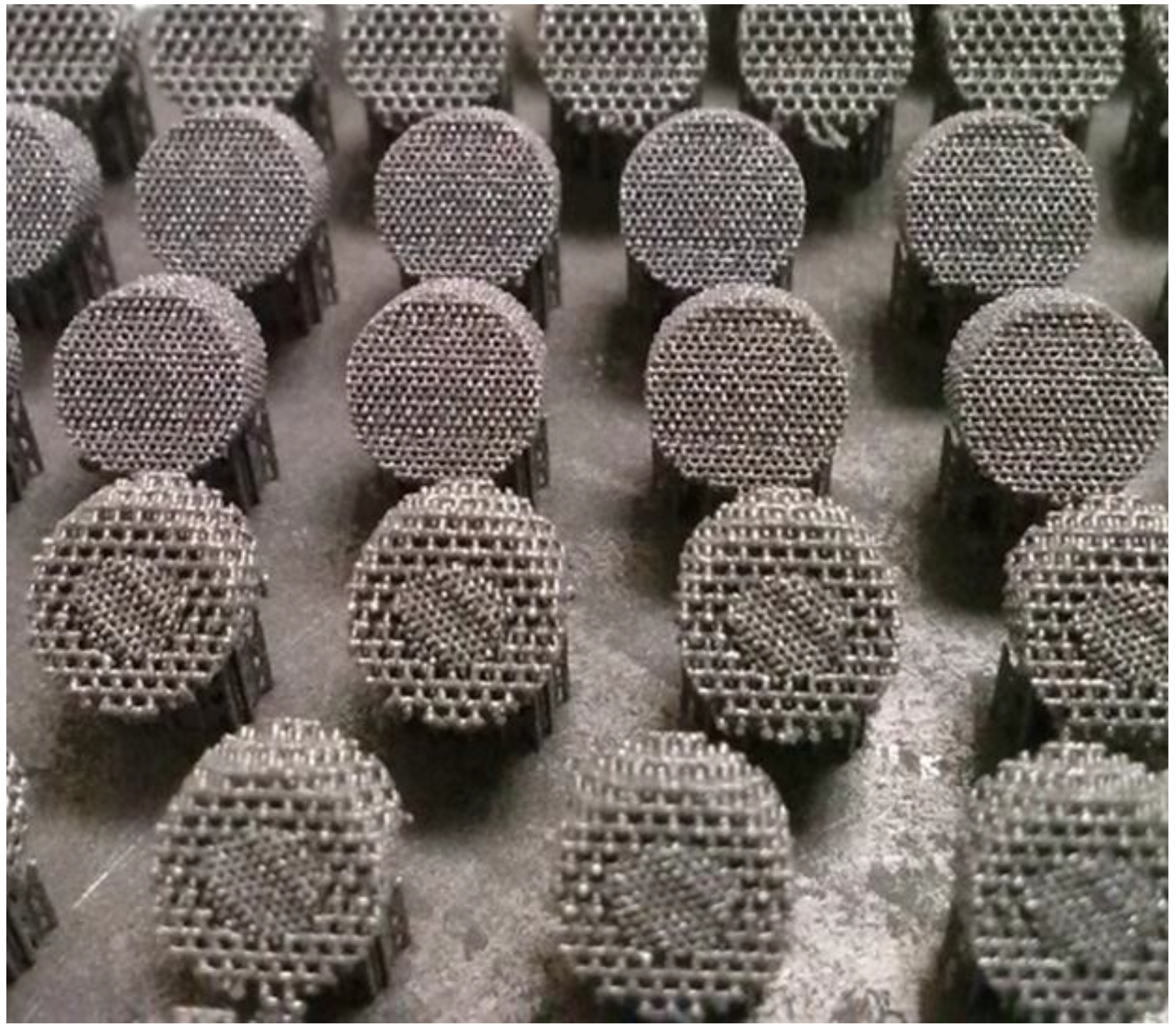
2.2. Scaffolds Fabrication

The titanium scaffolds were fabricated from CP Ti powder (Starbond Ti4, Scheftner Dental Alloys GmbH, Mainz, Germany) on a SLM 50 3D printer (Realizer GmbH, Borchen, Germany) for metals and their alloys. According to the manufacturer’s data, the Ti4 powder had a diameter of 10–45 µm, met titanium Grade 4 requirements and its purity was minimal 98.95 wt %. (max impurities: 0.5% Fe, 0.4% O, 0.08% C, 0.05% N and 0.125% H). The powder size distribution before the process was investigated in ethanol using a laser scattered light analyzer Horiba LA-950 (Horiba Ltd., Kyoto, Japan). During the fabrication, an argon inert atmosphere was used and the oxygen value was kept in the volume in the range of 0.2%–0.4%. Three series of scaffolds with various designed pore sizes: (1) 200 µm, (2) 500 µm and (3) bimodal 200 µm core + 500 µm shell, were fabricated. During fabrication, the scaffolds were oriented on the edge to minimalize the support area (Figure 2). The laser scanning speed and energy density delivered to the scaffolds for their consolidation were in the range of 325–375 mm/s and 91–151 J/mm3, respectively. A layer thickness of 25 µm was used. The detailed process parameters are summarized in the Table 1.

2.3. Chemical Polishing

Chemical polishing was performed in the hydrofluoric acid solutions [30,31] (1%–5% HF) for time 1–6 min. and in mixtures of hydrofluoric and nitric acids [33] (2.0/20%, 1.3/9.0%, 4.0/16%, 2.2/20% HF/HNO3 respectively) for 3–9 min. Each sample was polished in a separate beaker in an ultrasonic cleaner. Acid concentration and composition of the baths are summarized in the Table 2 and Table 3. The powders trapped between scaffolds struts were removed from the scaffolds before chemical polishing by compressed air and multiple washings in a distilled water using an ultrasonic cleaner. The mass of the samples was measured before and after chemical polishing. The microscopic observations before and after polishing were performed using HITACHI SU8000 (Hitachi Ltd., Tokyo, Japan) and Phenom PROX microscopes (Phenom-World BV, Eindhoven, Holland). Based on the mass change and microscopic observations, the bath composition was optimized for each scaffold type. The characterization was performed on non-polished and scaffolds.

2.4. Contact Angle Measurements

Contact angle measurements were made using the Contact Angle System OCA (DataPhysics, Filderstadt, Germany). The measurements were performed on the thin (~1 mm) solid plates fabricated with the same process parameters and energy densities as delivered to the material for a porous scaffolds. The 9 measurements were performed on each chemically polished and non-polished material type 1 µL of distilled water was placed on the samples, photographed and analyzed using software delivered with the goniometer. Each measurement was performed 6 times.

2.5. Density Measurements and µ-CT Reconstruction

The SKYSCAN 1172 X-Ray µ-CT (Bruker, Billerica, MA, USA) was used for open/closed porosity, struts/pore size and surface area calculations using NRecon, DataViewer, CTAn, CTVol and CTVox software (Bruker, Billerica, MA, USA). The X-ray tube voltage was 100 kV and the current was 100 µA. The Al + Cu filter was used during measurements. The X-ray projections were obtained at 0.3° intervals with a scanning angular rotation of 180°. 8 frames were averaged for each rotation. The exposure time was 1160 ms and pixel size was set on 4.90 µm. Additionally, ring artifacts were reduced through selection of a random movement amplitude of 50. The open/closed porosity and struts/pore size µ-CT results were compared to ImageJ measurements on SEM pictures which were made using the Hitachi SU8000 (Hitachi Ltd., Tokyo, Japan).

2.6. Mechanical Tests

The compression tests were performed using the electromechanical testing machine Zwick Roell Z005 (Zwick GmbH & Co. KG, Ulm, Germany). 5 chemically polished and 5 non-polished scaffolds with different porosities were tested. The used strain rate was 10−3 1/s, which corresponds to the crossbar travel speed of 0.004 mm/s. Young’s modulus was calculated as the slope of the initial linear range of the stress-strain curve. Strain measurements were done by using non-contact digital image correlation method.

2.7. In Vitro Cell Response

Samples were sterilized in 70% ethanol for 1 h, followed by four washes with phosphate buffered saline (PBS; Sigma, Steinheim, Germany) and overnight incubation in an expansion medium (minimum essential medium alpha, α-MEM; Gibco, Thermo Fisher Scientific, Paisley, UK) supplemented with 10% FBS (fetal bovine serum; South American Origin, Biowest, Nuaillé, France), 1% PSN (5 units/ml of penicillin, 5 mg/ml of streptomycin, 10 mg/ml neomycin; Sigma, St. Louis, MO, USA) and 1 ng/mL human basic fibroblast growth factor (Sigma, Jerusalem, Israel). Normal human bone marrow derived mesenchymal stem cells (hMSCs) were purchased from Lonza (Walkersville, MD, USA). The cells were isolated from bone marrow of a 40-year-old female. The cells used in the experiments were from passage 4. MSCs were seeded at a density of 2.5 × 10⁵ per scaffold and incubated in expansion for 7 days and in osteogenic medium (α-MEM supplemented with 10% FBS, 1% PSN, 50 µM ascorbic acid phosphate (Sigma, Osaka, Japan), 2 mM β-glycerophosphate (Sigma, St. Louis, MO, USA), 10 nM 1,25-dihydroxy-vitamin D3 (Sigma, Jerusalem, Israel) and 10 nM dexamethasone (Sigma, Shanghai, China) for an additional 7 days.

2.7.1. Cell Viability

The MTS assay (CellTiter 96® AQueous one solution cell proliferation assay; Promega, Madison, WI, USA) was carried out as an index of a viable cell number. After 24 h, scaffolds with cells were washed with α-MEM without FBS and placed in a new 24-well plate containing 700 µL of α-MEM w/o FBS. Then, 140 µL of MTS was added to each well and incubated for 2 h. The MTS assay was also conducted in wells used for a 24 h incubation of cell-laden scaffolds to estimate cell retention within scaffolds with different pore sizes. After 7 days of culture, hMSC viability was assessed qualitatively using live-dead fluorescent cell imagining kit (R37601, Molecular Probes, Thermo Fisher Scientific, Eugene, OR, USA). The scaffolds were washed twice with PBS and incubated with the mixture of live-dead dyes at 37 °C for 30 min. The cells were visualized using a fluorescent microscope Leica TCS SP8 (Leica Microsystems GmbH, Wetzlar, Germany) and filter sets corresponding to the fluorescence of interest.

2.7.2. Cell Differentiation

Alkaline phosphatase (ALP) activity was used as an indicator of hMSCs differentiation towards osteogenic lineage. After 7 and 14 days in culture, the samples were washed three times with PBS and frozen in 1 mL of deionized water. After thawing, the samples were vortexed and diluted with deionized water to yield concentrations suitable for further analysis. Total protein concentration (TPC) was determined using micro-BCA assay (QuantiPro BCA Assay Kit; Sigma, St. Louis, MO, USA). The ALP activity was measured spectrophotometrically using para-nitrophenyl phosphate (pNPP) as a substrate (Phosphatase Substrate Kit, Thermo Fisher Scientific, Rockford, IL, USA). Concentration of para-nitrophenol was calculated from a standard curve and normalized to the TPC.

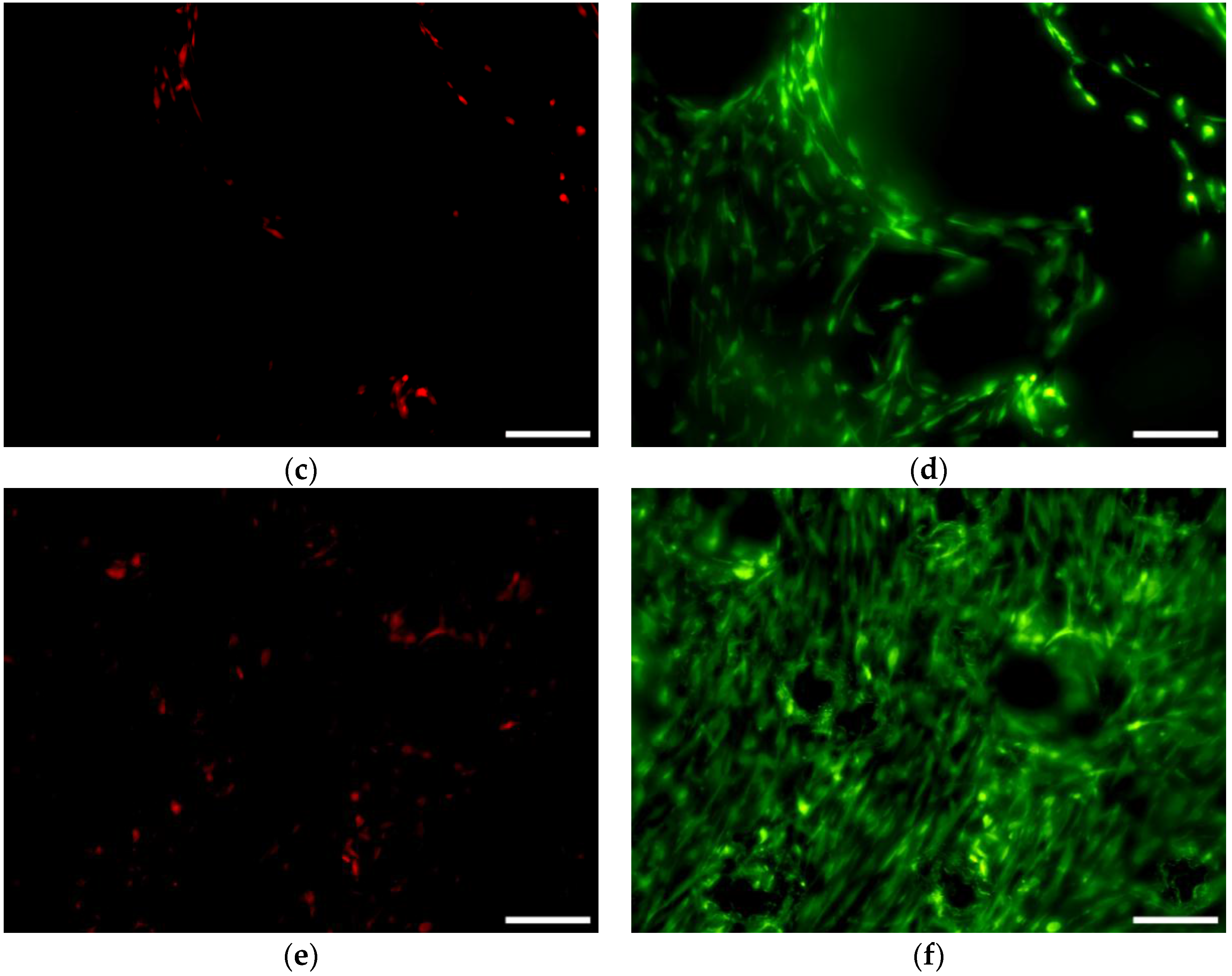
2.7.3. Confocal and Scanning Electron Microscopy

Cells cultured for 1 day were fixed with a 3% glutaraldehyde solution. For confocal microscopy, the cells were labeled with DiD dye (D307; Molecular Probes, Thermo Fisher Scientific) and visualized at a 633 nm wavelength using a Leica TCS SP8 confocal microscope (Leica Microsystems GmbH, Wetzlar, Germany). For scanning electron microscopy, the fixed cells were washed 3 times with deionized water, followed by dehydration with an ethanol gradient (50%, 70%, 90% and 99%) and hexamethyldisilazane treatment (Sigma, St. Louis, MO, USA). The cells were visualized at an acceleration voltage of 5–10 keV in secondary electrons (SE) mode at various magnifications using a Hitachi SU8000 microscope (Hitachi Ltd., Tokyo, Japan).

3. Results and Discussion

3.1. Powder Characterization

The average size of the Starbond Ti4 powder was equal to 39 ± 13 µm. The size distribution of the powder is shown in Figure 3a while its morphology is shown in Figure 3b. The size of the powder particles observed in the SEM micrographs was in agreement with manufacturer’s data and results obtained by a laser analyzer. We have not observed any influence of the particles deviating significantly from the average value on the selective laser melting process.

3.2. Compliance with CAD Model

All three series of the scaffolds were successfully fabricated using the edge orientation, independently on pore size used in the CAD model. The edge orientation helped to remove the porous scaffolds from supports without destroying their design. The supports which were designed manually for fabricated structures ensured mechanical stability during processing and helped in heat dissipation during processing. However, small struts deformation could be seen on the first melted layers of the scaffolds with 500 µm pores (Figure 2). This deformation was not seen in the scaffolds with the smallest pore size of 200 µm. Based on the obtained results, we suggest that for edge oriented scaffolds with designed 500 µm pores, a bigger support structure or different laser scan strategy, with smaller hatch distance, should be used. The average dimensions and mass of the fabricated sample series were measured to check the process repeatability. The average height, diameter and mass is summarized in Table 4. For each porosity (200, 500 and 200 + 500 µm), 10 scaffolds from at least 3 fabrication batches were measured. The obtained samples were very regular and standard deviation did not exceed 2.4% and 5.4% for dimensions and mass, respectively, for all designed types of structures. The pore size of the scaffolds was slightly smaller than in CAD model, which is typical for scaffolds fabricated by selective laser melting. Obtaining pores smaller than those designed in the CAD model was the authors’ intention because chemical polishing enlarges pore size. The aim of this research was to remove unmelted powder particles and achieve a pore size around 200 µm and 500 µm.

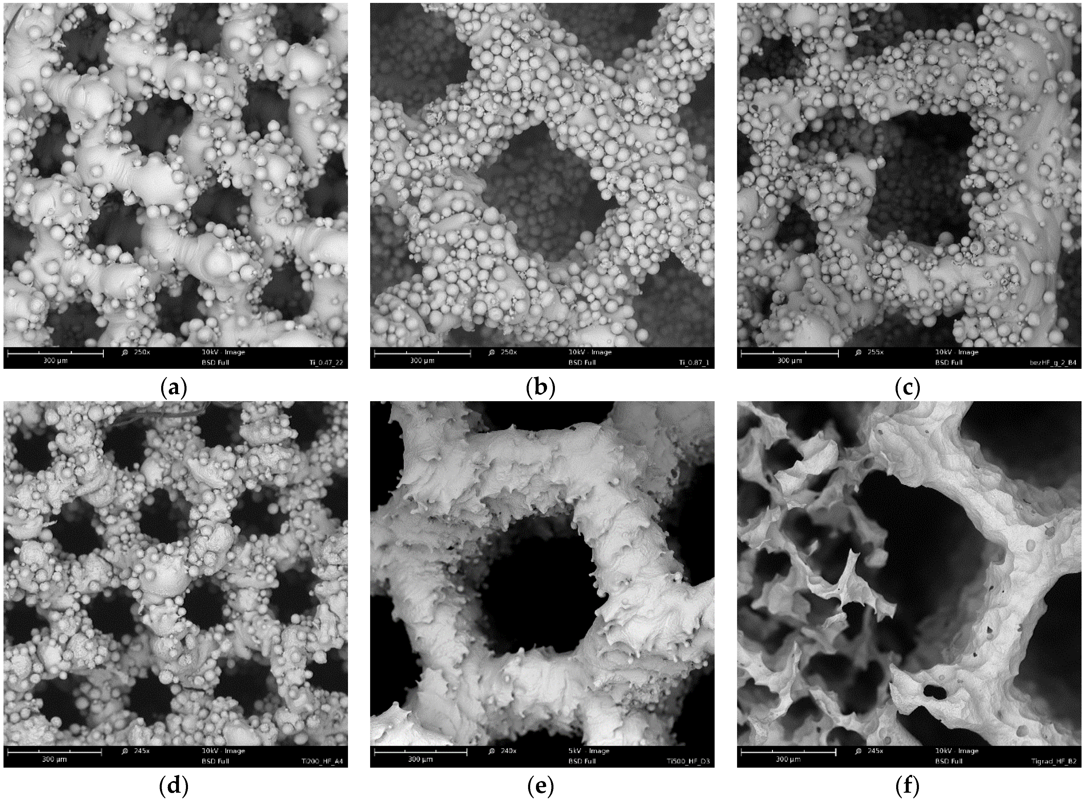
3.3. Chemical Polishing

The fabricated scaffolds were chemically polished in HF acids (Table 2) and HF/HNO3 acid mixtures (Table 3). The HF baths contained 1%–5% HF, and balanced distilled H2O. The polishing time was 1, 3, and 6 min. The mass changes after chemical polishing in HF solutions are shown in Figure 4 and the representative areas of the polished/non-polished scaffolds are depicted in Figure 5. Although structures were built under a 45°, there was no visible struts waviness on non-polished scaffolds (Figure 5), which is common defect of additive manufactured parts [37,38]. Independently from the pore sizes in the scaffolds, increasing both the time or/and HF concentration decreased the scaffold mass. The scaffolds with the higher mass (200 µm and 200 + 500 µm) were characterized by a higher mass change than 500 µm scaffolds for the most HF concentrations and polishing times. A decrease of scaffolds mass greater than 30% was observed for the polishing most times equal or higher than 3 min with a simultaneous HF concentration of 3% or higher. These HF polished scaffolds should undoubtedly be excluded from the TE applications, because their cells were disintegrated and pitting at the struts surface was observed (Figure 5f). Scaffolds in which mass was lost after polishing below 10% had uniform struts and also cells connections maintained but just some pitting on the unmelted particles was observed (Figure 5d). The mass loss in a range from 10% to 30% was connected with unmelted particles removal, with usually preserved struts interconnectivity but the struts surface became sharp and irregular (Figure 5e). To summarize, the application of solely HF baths was not suitable for chemical polishing of Ti scaffolds because it either destroyed their structure or did not remove the unmelted particles form the surface of the struts.
The polishing in HF/HNO3 solutions was performed to reduce the intensity of the process and limit the phenomena of titanium embrittlement occurring in HF solutions and caused by hydrogen generation [39]. Based on the experimental polarization curves [19], the best 4 systems for titanium polishing were proposed (Table 3). The polishing in the bath no. 3 (4.0% HF/16% HNO3) was so intensive that it resulted in complete dissolution of the scaffolds already after around only 1 min of exposure, independent of pore size. The mass changes caused by the HF/HNO3 polishing baths are summarized in Figure 6. The highest weight loss was observed for the 500 µm pore size regardless of the composition of the used baths. This could be caused by better penetration of the HF/HNO3 mixture than the HF. During the HF polishing we observed a very high hydrogen generation, which could hinder the acid penetration. In the HF/HNO3 solutions the hydrogen generation was negligible, so the structure permeability was mostly influenced by the pore size. Furthermore, the mass loss of the 500 µm scaffolds could be influenced by the energy density delivered to the material, which for the 500 µm structure was only 91 J/mm3 while for 200 µm and 200 + 500 µm it was 131 and 151 J/mm3, respectively. A smaller energy density could result in less melted titanium particles in the heat affected zone (HAZ), thus easier polishing. Based on the SEM observations of all scaffolds polished in this study, an adequate bath for each pore size was chosen. The polishing occurred for 6 min in baths consisting of 2.0% HF/20% HNO3 and 1.3% HF/9.0% HNO3 were chosen for 200 µm and 500 µm pore structures, respectively. Optimization of the bath composition for structure 200 + 500 µm showed that the most uniform removal of unmelted particles could be obtained in a bath with a slightly higher HF acid concentration than for 200 µm pores. Therefore, the proposed bath composition for structures 200 + 500 µm is 2.2% HF/20% HNO3 applied for 6 min. The mass change of scaffolds polished in these baths was 28%, 64% and 43% for 200 µm, 500 µm, 200 + 500 µm structures, respectively. The as made scaffolds and the scaffolds polished in the proposed baths are shown in Figure 7.
The scaffolds shown in Figure 7d–f were uniformly polished in the case of all designed pore structures. The surface after removal of unmelted titanium particles, by polishing in the proposed baths, should not be sensitive to pitting corrosion due to high pores interconnectivity [40]. The highest mass change was observed on the SEM pictures for 500 µm pore structure (Figure 7b,e), where struts drastically changed their dimensions. The struts connections between cells in 200 µm (Figure 7d) and 500 µm structures (Figure 7e) as well as the connection between 200 and 500 µm structure in bimodal scaffolds were preserved (Figure 7f). Wild et al. [41] showed in a rabbit model that bridging of a bone defect increased when scaffolds struts were cleaned from powder particles. In his research, the cleaning was performed by sandblasting followed by acid-etching. In our opinion our guideline, in which only acid polishing was used, is more cost-efficient. We should also consider the fact that uniform sandblasting would be very difficult in pores as small as 200 µm and in scaffolds composed of cells with complicated geometry. Furthermore, the proposed baths had a positive effect on the wettability. The values of the water contact angle decreased drastically for all types of surfaces after the acid treatment (Figure 8). The lowest decrease of water contact angle (WCA) measured in the case of the sample 200 + 500 µm was probably caused by the highest amount of energy density J/mm3 delivered to this material, which led to the strongest melting powders and thus the smallest polishing effect.

3.4. µ-CT Reconstruction and SEM Measurements

The pore and strut size obtained using the µ-CT and SEM are shown in Figure 9 and Figure 10. The results indicated strong effect of the acid treatment on change of the measured parameters (marked on graphs with “P”). Dimensions of the pores and struts of all fabricated samples decreased due to acid treatment and were closer to the CAD models. The pore sizes of scaffolds after chemical polishing measured by µ-CT was equal to 205 µm, 470 µm and 200 + 470 µm for the designed pore 200 µm, 500 µm and 200 + 500 µm, respectively. The pore sizes obtained after chemical polishing were more than twice smaller comparing with the SLM and electron beam melting (EBM) fabricated structures in other studies [30,34]. The scaffolds exhibited an interconnected pore system, which increased after polishing (Figure 11). There were no trapped metallic powders, missed cells or other irregularities which could affect mechanical properties or permeability (Figure 12). The overall open porosity after polishing was equal to 62% and 80% for scaffolds with designed pore sizes 200 µm and 500 µm, respectively. The slightly lower porosity was obtained in the bimodal structures and was equal to 58% and 77% for core and shell, respectively. The average pore and strut size varied between 3D µ-CT and 2D microscopic measurements. The mean diameter of pores obtained by the 3D method were usually larger than those which were determined by the 2D measurements. This was an effect of the higher number of degrees of freedom in 3D than 2D method to fit a maximum sphere to the measured pores. This issue was found to be dependent on the cell shape and higher for the rectangular pores [19].

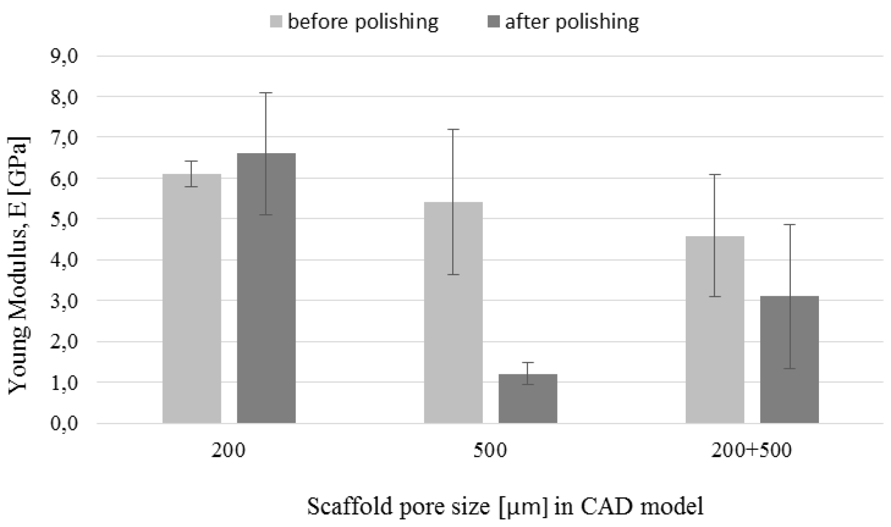
3.5. Mechanical Tests

The compression strength and Young’s modulus determined based on the compression tests are shown in Figure 13 and Figure 14, respectively. Both parameters decreased after polishing for all types of the fabricated structures. However, the decrease was more pronounced in the case of scaffolds with 500 µm pores. Compressive strength of those scaffolds decreased over 4 times after polishing. The decrease was caused by 64% mass change due to the polishing, as well as increase of pore size from 425 to 470 µm and decrease of strut size from 240 to 170 µm. The mass change of polished structures with designed pores 200 µm and 200 + 500 µm was equal 28% and 43%, respectively. This suggests that the lower decrease of mechanical strength in the case of scaffolds was caused by smaller changes in dimensions of these structures after polishing. The Young’s modulus values before chemical treatments were 6.1 GPa, 5.4 GPa and 4.6 GPa for pore sizes 200 µm, 500 µm and 200 + 500 µm, respectively. The general rule in the conventional powder metallurgy is that the increased porosity causes decrease of the Young’s modulus [42,43]. However, in additive manufacturing the effect of pore geometry, orientation and arrangement should also be considered [44]. The values of mechanical strength obtained in our study were comparable to results reported by other authors for non-polished SLM and EBM processed Ti-6Al-4V scaffolds with diamond structure [45,46]. We suggest that high standard deviation of obtained results, mostly for 500 µm pore size non-polished structures, was influenced by the samples’ geometry. As it was mentioned before, struts of these scaffolds were less regular in the corners due to the edge building orientation. In addition, the small size of the cylinder (only 6 mm diameter and 4 mm height) filled with a bigger cell structure (0.87 mm) were less regular than those filled with smaller structure (0.47 mm). This could results in high standard deviation of the obtained mechanical properties. On the other hand, in the case of polished samples, the high standard deviation was more noticeable for structures made with the 200 µm pores. In our opinion, it was an effect of a higher probability of destroying the struts during polishing of smaller structures. Similarly, the probability of destroying cells was high in bimodal 200 + 500 µm structures which also were sensitive to etching of connections between the core and the shell.

3.6. In-Vitro Cell Response

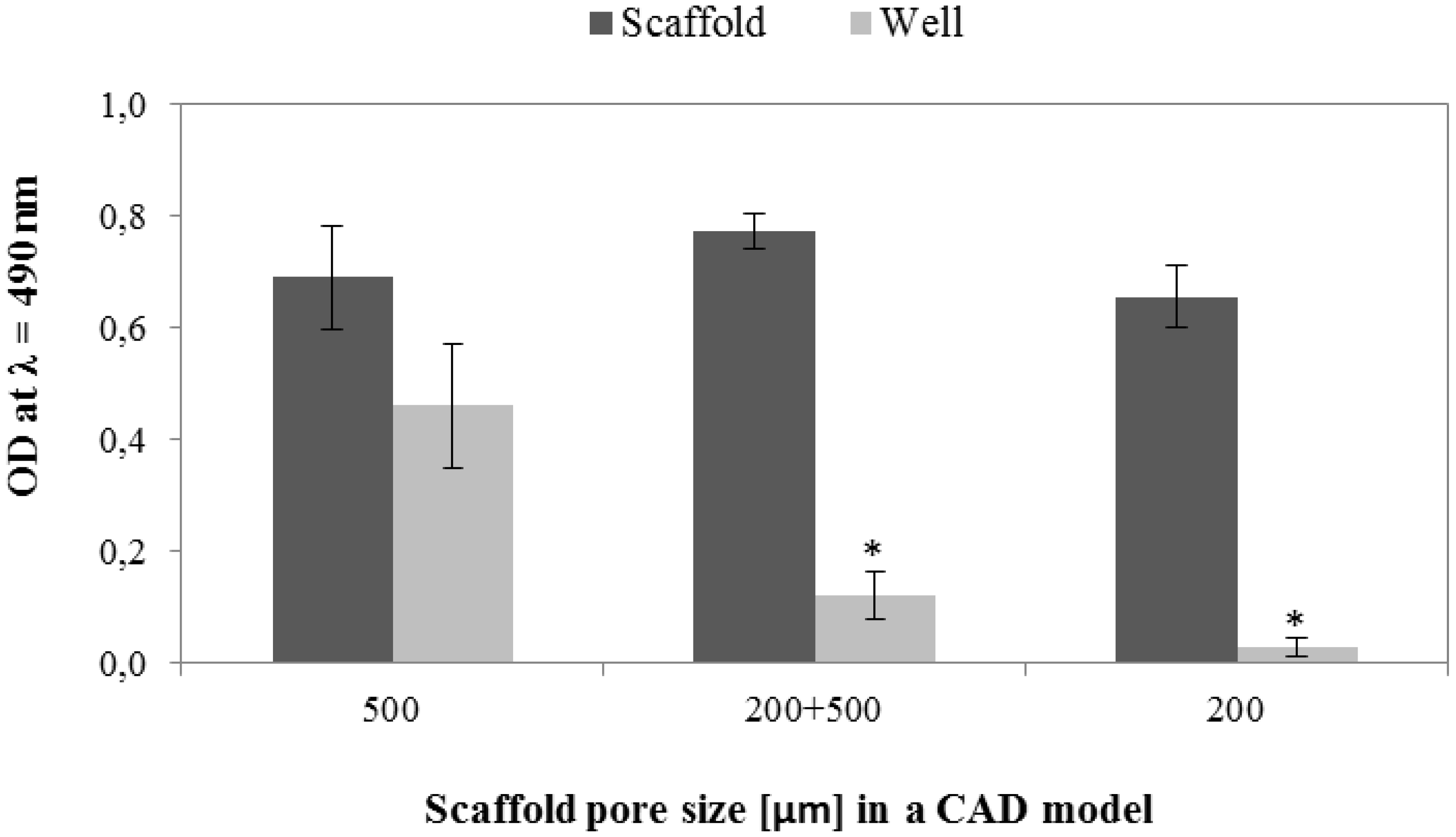
3.6.1. Cell Viability and Seeding Efficiency

The MTS results obtained after 24 h of incubation in expansion medium indicated no significant effect of pores size on the hMSCs viability (Figure 15). On the other hand, the number of viable hMSCs was significantly higher in wells used for cell seeding of scaffolds with 500 µm pores than scaffolds with 200 µm and bimodal pores. Those results suggest that less cells was retained within scaffolds with bigger pores. An alternative explanation can be lower metabolic activity of hMSCs growing within scaffolds with small pores due to lower diffusion of nutrients or hindered diffusion of formazan (MTS reduction product) to the culture medium. The latter possibility is supported by microscopic observations, which revealed higher cell densities on the scaffolds with small pores and in the 200 µm-core of the bimodal scaffolds (Figure 16 and Figure 17). Additionally, negative effect of increasing pore size on seeding efficiency was reported in the case of polymeric scaffolds fabricated by means of additive manufacturing [47,48,49].
The results of viability determined using fluorescent live-dead assay are depicted in Figure 18. Predominance of live cells was observed on all scaffolds at day 7 of culture. Additionally, cell density increased with decreasing pore size. The increased cell number on the scaffolds with smaller pores could be caused by higher cell retention during seeding procedure. Additionally, higher surface area available for cells adhesion and smaller distance between the struts ensured space for cell proliferation and enabled bridging of the struts. On the other hand, the improved hMCs growth could be only superficial due to hindered diffusion of nutrients and metabolites within the smaller pores. However, additional study must be performed to address this issue.

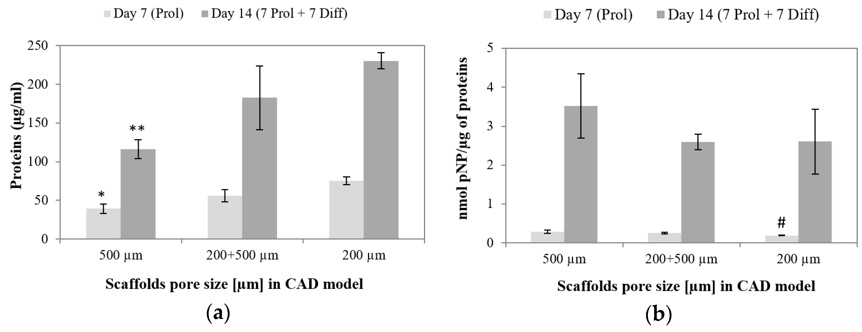
3.6.2. Osteogenic Differentiation

The highest ALP activity per cell was measured within 500 µm pore scaffolds both after 7 days of expansion and additional 7 days of osteogenic differentiation (Figure 19b). The ALP activity was conversely correlated to total protein concentration, which suggests that differentiation was more advanced on scaffolds which supported cell proliferation to lesser extent. A similar trend was observed in the case of differentiation of MSCs within 3D polymeric and composite scaffolds produced by additive manufacturing [50,51]. It is worth noting that the TPC confirms the microscopic observations of the samples: the scaffolds with the smallest pores yielded the highest cell density and TPC.

4. Conclusions

In the present study, a detailed guideline for fabrication and post-treatment of novel titanium scaffolds was developed. The scaffolds were built up from diamond elemental cell with two different sizes which yield three different scaffolds architectures. Pore sizes after removal of the unmelted powder particles were almost equal to those designed in the CAD models (200 µm, 500 µm and 200 + 500 µm). The mixtures of the HF/HNO3 acids were successfully used for uniform etching of the as prepared SLM structures with pore size as little as 200 µm. Such results were impossible to obtain using solely HF acids. The uniform pore size and removal of the powder particles after chemical polishing in HF/HNO3 solutions were confirmed by the µ-CT reconstructions and SEM images. An additional benefit of the surface polishing was a decrease in water contact angle by 52%–75%. The mechanical properties of the fabricated cellular structures were similar to those of human bone, which might minimize the stress-shielding effect. Scaffolds with 200 µm pores exhibited the highest cell retention which yielded the highest cell density at later time points. However, bridging of the small pores by cells could hinder diffusion of nutrients and metabolites. Therefore, the bimodal scaffolds offer a possibility to combine high cell retention within the small pores with improved diffusion, and thus cells nutrition, through the big pores. The obtained results show that combination of different pore sizes is a perspective tool for design and fabrication of the scaffolds with gradient properties which allows to mimics human bone to a greater extent than solutions utilized nowadays.

Acknowledgments

This work was supported by the European Regional Development Fund within the Innovative Operational Programme in the framework of the BIO-IMPLANT project (Grant No. POIG.01.01.02-00-022/09) and National Center for Research and Developments PBS project LasIMP (Grant No. PBS3/A5/53/2015).

Author Contributions

Wojciech Święszkowski and Krzysztof J. Kurzydłowski conceived and designed the experiments; Bartłomiej Wysocki, Joanna Idaszek, Karolina Strzelczyk, Tomasz Brynk and Karol Szlązak performed the experiments and analyzed the data; Bartłomiej Wysocki contributed reagents/materials/analysis tools; Bartłomiej Wysocki and Joanna Idaszek wrote the paper.

Conflicts of Interest

The authors declare no conflict of interest. The founding sponsors had no role in the design of the study; in the collection, analyses, or interpretation of data; in the writing of the manuscript, and in the decision to publish the results.

References

  1. Sharpless, N.E.; DePinho, R.A. How stem cells age and why this makes us grow old. Nat. Rev. Mol. Cell. Biol. 2007, 8, 703–713. [Google Scholar] [CrossRef] [PubMed]
  2. Griffith, L.G.; Naughton, G. Tissue engineering—Current challenges and expanding opportunities. Science 2002, 295, 1009–1014. [Google Scholar] [PubMed]
  3. Stoltz, J. Influence of mechanical forces on cells and tissues. Regener. Med. Cell. Ther. 2012, 77, 111. [Google Scholar]
  4. Schantz, J.T.; Brandwood, A.; Hutmacher, D.W.; Khor, H.L.; Bittner, K. Osteogenic differentiation of mesenchymal progenitor cells in computer designed fibrin-polymer-ceramic scaffolds manufactured by fused deposition modeling. J. Mater. Sci. Mater. Med. 2005, 16, 807–819. [Google Scholar] [CrossRef] [PubMed]
  5. Amini, A.R.; Laurencin, C.T.; Nukavarapu, S.P. Bone tissue engineering: Recent advances and challenges. Crit. Rev. Biomed. Eng. 2012, 40, 363–408. [Google Scholar] [CrossRef] [PubMed]
  6. Swieszkowski, W.; Tuan, B.H.S.; Kurzydlowski, K.J.; Hutmacher, D.W. Repair and regeneration of osteochondral defects in the articular joints. Biomol. Eng. 2007, 24, 489–495. [Google Scholar] [CrossRef] [PubMed]
  7. Shearn, J.T.; Kinneberg, K.R.; Dyment, N.A.; Galloway, M.T.; Kenter, K.; Wylie, C.; Butler, D.L. Tendon tissue engineering: Progress, challenges, and translation to the clinic. J. Musculoskelet. Neuronal Interact. 2011, 11, 163–173. [Google Scholar] [PubMed]
  8. Ryan, G.; Pandit, A.; Apatsidis, D.P. Fabrication methods of porous metals for use in orthopaedic applications. Biomaterials 2006, 27, 2651–2670. [Google Scholar] [CrossRef] [PubMed]
  9. Otsuki, B.; Takemoto, M.; Fujibayashi, S.; Neo, M.; Kokubo, T.; Nakamura, T. Pore throat size and connectivity determine bone and tissue ingrowth into porous implants: Three-dimensional micro-CT based structural analyses of porous bioactive titanium implants. Biomaterials 2006, 27, 5892–5900. [Google Scholar] [CrossRef] [PubMed]
  10. Khoda, A.K.M.B.; Koc, B. Functionally heterogeneous porous scaffold design for tissue engineering. Comput. Aided Des. 2013, 45, 1276–1293. [Google Scholar] [CrossRef] [Green Version]
  11. Wieding, J.; Wolf, A.; Bader, R. Numerical optimization of open-porous bone scaffold structures to match the elastic properties of human cortical bone. J. Mech. Behav. Biomed. Mater. 2014, 37, 56–68. [Google Scholar] [CrossRef] [PubMed]
  12. Miao, X.; Sun, D. Graded/gradient porous biomaterials. Materials 2009, 3, 26–47. [Google Scholar] [CrossRef]
  13. Karageorgiou, V.; Kaplan, D. Porosity of 3D biomaterial scaffolds and osteogenesis. Biomaterials 2005, 26, 5474–5491. [Google Scholar] [CrossRef] [PubMed]
  14. Akay, G.; Birch, M.A.; Bokhari, M.A. Microcellular polyHIPE polymer supports osteoblast growth and bone formation In Vitro. Biomaterials 2004, 25, 3991–4000. [Google Scholar]
  15. Vasconcellos, L.M.; Leite, D.O.; Oliveira, F.N.; Carvalho, Y.R.; Cairo, C.A. Evaluation of bone ingrowth into porous titanium implant: histomorphometric analysis in rabbits. Braz. Oral Res. 2010, 24, 399–405. [Google Scholar] [CrossRef] [PubMed]
  16. Hollander, D.A.; von Walter, M.; Wirtz, T.; Sellei, R.; Schmidt-Rohlfing, B.; Paar, O.; Erli, H.-J. Structural, mechanical and in vitro characterization of individually structured Ti–6Al–4V produced by direct laser forming. Biomaterials 2006, 27, 955–963. [Google Scholar] [CrossRef] [PubMed]
  17. Stangl, R.; Rinne, B.; Kastl, S.; Hendrich, C. The influence of pore geometry in cp Ti-implants—A cell culture investigation. Euro. Cells Mater. 2001, 2, 1–9. [Google Scholar]
  18. Warnke, P.H.; Douglas, T.; Wollny, P.; Sherry, E.; Steiner, M.; Galonska, S.; Becker, S.T.; Springer, I.N.; Wiltfang, J.; Sivananthan, S. Rapid prototyping: Porous titanium alloy scaffolds produced by selective laser melting for bone tissue engineering. Tissue Eng. Part C Methods 2009, 15, 115–124. [Google Scholar] [CrossRef] [PubMed]
  19. Van Bael, S.; Chai, Y.C.; Truscello, S.; Moesen, M.; Kerckhofs, G.; Van Oosterwyck, H.; Kruth, J.P.; Schrooten, J. The effect of pore geometry on the in vitro biological behavior of human periosteum-derived cells seeded on selective laser-melted Ti6Al4V bone scaffolds. Acta Biomater. 2012, 8, 2824–2834. [Google Scholar] [CrossRef] [PubMed]
  20. Thieme, M.; Wieters, K.-P.; Bergner, F.; Scharnweber, D.; Worch, H.; Ndop, J.; Kim, T.; Grill, W. Titanium powder sintering for preparation of a porous functionally graded material destined for orthopaedic implants. J. Mater. Sci. Mater. Med. 2001, 12, 225–231. [Google Scholar] [CrossRef] [PubMed]
  21. Suk, M.-J.; Choi, S.-I.; Kim, J.-S.; Kim, Y.D.; Kwon, Y.-S. Fabrication of a porous material with a porosity gradient by a pulsed electric current sintering process. Metals Mater. Int. 2003, 9, 599–603. [Google Scholar] [CrossRef]
  22. Harrysson, O.L.A.; Marcellin-Little, D.J.; Horn, T.J. Applications of metal additive manufacturing in veterinary orthopedic surgery. JOM 2015, 67, 647–654. [Google Scholar] [CrossRef]
  23. Linxi, Z.; Quanzhan, Y.; Guirong, Z.; Fangxin, Z.; Gang, S.; Bo, Y. Additive manufacturing technologies of porous metal implants. China Foundry 2014, 11, 322–331. [Google Scholar]
  24. Skibinski, J.; Cwieka, K.; Kowalkowski, T.; Wysocki, B.; Wejrzanowski, T.; Kurzydlowski, K.J. The influence of pore size variation on the pressure drop in open-cell foams. Mater. Des. 2015, 87, 650–655. [Google Scholar] [CrossRef]
  25. Beer, N.D.; Merwe, A.V.D. Patient-specific intervertebral disc implants using rapid manufacturing technology. Rapid Prototyp. J. 2013, 19, 126–139. [Google Scholar] [CrossRef]
  26. Calignano, F. Design optimization of supports for overhanging structures in aluminum and titanium alloys by selective laser melting. Mater. Des. 2014, 64, 203–213. [Google Scholar] [CrossRef]
  27. Cloots, M.; Spierings, A.; Wegener, K. Assessing new support minimizing strategies for the additive manufacturing technology SLM. In Proceedings of the Solid Freeform Fabrication Symposium, Austin, TX, USA, 12–13 August 2013.
  28. Lukas, L.; Christoph, F.; Romy, P.; Uta, K.; Jürgen, E. Comparison of different post processing technologies for SLM generated 316l steel partsnull. Rapid Prototyp. J. 2013, 19, 173–179. [Google Scholar]
  29. Kerckhofs, G.; Van Bael, S.; Pyka, G.; Schrooten, J.; Wevers, M. Investigation of the influence of surface roughness modification of bone tissue engineering scaffolds on the morphology and mechanical properties. In Proceedings of SkyScan User Meeting, Mechelen, Belgium, 7–9 July 2010.
  30. Łyczkowska, E.; Szymczyk, P.; Dybała, B.; Chlebus, E. Chemical polishing of scaffolds made of Ti–6Al–7Nb alloy by additive manufacturing. Arch. Civil Mech. Eng. 2014, 14, 586–594. [Google Scholar] [CrossRef]
  31. Truscello, S.; Kerckhofs, G.; Van Bael, S.; Pyka, G.; Schrooten, J.; Van Oosterwyck, H. Prediction of permeability of regular scaffolds for skeletal tissue engineering: A combined computational and experimental study. Acta Biomater. 2012, 8, 1648–1658. [Google Scholar] [CrossRef] [PubMed]
  32. Yang, L.; Harrysson, O.; Cormier, D.; West, H.; Gong, H.; Stucker, B. Additive manufacturing of metal cellular structures: Design and fabrication. JOM 2015, 67, 608–615. [Google Scholar] [CrossRef]
  33. Sutter, E.M.M.; Goetz-Grandmont, G.J. The behaviour of titanium in nitric-hydrofluoric acid solutions. Corrosion Sci. 1990, 30, 461–476. [Google Scholar] [CrossRef]
  34. Hasib, H.; Harrysson, O.L.; West, H.A., II. Powder removal from Ti-6Al-4V cellular structures fabricated via electron beam melting. JOM 2015, 67, 639–646. [Google Scholar] [CrossRef] [Green Version]
  35. Parthasarathy, J.; Starly, B.; Raman, S.; Christensen, A. Mechanical evaluation of porous titanium (Ti6Al4V) structures with electron beam melting (EBM). J. Mech. Behav. Biomed. Mater. 2010, 3, 249–259. [Google Scholar] [CrossRef] [PubMed]
  36. Van Bael, S.; Kerckhofs, G.; Moesen, M.; Pyka, G.; Schrooten, J.; Kruth, J.P. Micro-CT-based improvement of geometrical and mechanical controllability of selective laser melted Ti6Al4V porous structures. Mater. Sci. Eng. A 2011, 528, 7423–7431. [Google Scholar] [CrossRef]
  37. Byun, H.-S.; Lee, K.H. Determination of the optimal build direction for different rapid prototyping processes using multi-criterion decision making. Robot. Comp. Integr. Manuf. 2006, 22, 69–80. [Google Scholar] [CrossRef]
  38. Campbell, R.I.; Martorelli, M.; Lee, H.S. Surface roughness visualisation for rapid prototyping models. Comp. Aided Des. 2002, 34, 717–725. [Google Scholar] [CrossRef]
  39. Louthan, M., Jr. Hydrogen embrittlement of metals: A primer for the failure analyst. J. Fail. Anal. Prev. 2008, 8, 289–307. [Google Scholar] [CrossRef]
  40. Seah, K.H.W.; Thampuran, R.; Teoh, S.H. The influence of pore morphology on corrosion. Corrosion Sci. 1998, 40, 547–556. [Google Scholar] [CrossRef]
  41. de Wild, M.; Schumacher, R.; Mayer, K.; Schkommodau, E.; Thoma, D.; Bredell, M.; Kruse Gujer, A.; Gratz, K.W.; Weber, F.E. Bone regeneration by the osteoconductivity of porous titanium implants manufactured by selective laser melting: A histological and micro computed tomography study in the rabbit. Tissue Eng. Part A 2013, 19, 2645–2654. [Google Scholar] [CrossRef] [PubMed] [Green Version]
  42. Kováčik, J. Correlation between Young's modulus and porosity in porous materials. J. Mater. Sci. Lett. 1999, 18, 1007–1010. [Google Scholar] [CrossRef]
  43. Dabrowski, B.; Swieszkowski, W.; Godlinski, D.; Kurzydlowski, K.J. Highly porous titanium scaffolds for orthopaedic applications. J. Biomed. Mater. Res. Part B Appl. Biomater. 2010, 95, 53–61. [Google Scholar] [CrossRef] [PubMed]
  44. Choren, J.A.; Heinrich, S.M.; Silver-Thorn, M.B. Young’s modulus and volume porosity relationships for additive manufacturing applications. J. Mater. Sci.e 2013, 48, 5103–5112. [Google Scholar] [CrossRef]
  45. Ahmadi, S.M.; Campoli, G.; Amin Yavari, S.; Sajadi, B.; Wauthle, R.; Schrooten, J.; Weinans, H.; Zadpoor, A.A. Mechanical behavior of regular open-cell porous biomaterials made of diamond lattice unit cells. J. Mech. Behav. Biomed. Mater. 2014, 34, 106–115. [Google Scholar] [CrossRef] [PubMed]
  46. Heinl, P.; Körner, C.; Singer, R.F. Selective Electron beam melting of cellular titanium: Mechanical properties. Adv. Eng. Mater. 2008, 10, 882–888. [Google Scholar] [CrossRef]
  47. Malda, J.; Woodfield, T.B.F.; Van Der Vloodt, F.; Wilson, C.; Martens, D.E.; Tramper, J.; Van Blitterswijk, C.A.; Riesle, J. The effect of PEGT/PBT scaffold architecture on the composition of tissue engineered cartilage. Biomaterials 2005, 26, 63–72. [Google Scholar] [CrossRef] [PubMed]
  48. Bartnikowski, M.; Klein, T.J.; Melchels, F.P.W.; Woodruff, M.A. Effects of scaffold architecture on mechanical characteristics and osteoblast response to static and perfusion bioreactor cultures. Biotechnol. Bioeng. 2014, 111, 1440–1451. [Google Scholar] [CrossRef] [PubMed]
  49. Lee, J.W.; Ahn, G.; Cho, D.W.; Kim, J.Y. Evaluating cell proliferation based on internal pore size and 3D scaffold architecture fabricated using solid freeform fabrication technology. J. Mater. Sci. Mater. Med. 2010, 21, 3195–3205. [Google Scholar] [CrossRef] [PubMed]
  50. Yilgor, P.; Sousa, R.A.; Reis, R.L.; Hasirci, N.; Hasirci, V. 3D plotted PCL scaffolds for stem cell based bone tissue engineering. Macromol. Symp. 2008, 269, 92–99. [Google Scholar] [CrossRef] [Green Version]
  51. Idaszek, J.; Bruinink, A.; Święszkowski, W. Ternary composite scaffolds with tailorable degradation rate and highly improved colonization by human bone marrow stromal cells. J. Biomed. Mater. Res. A 2015, 103, 2394–2404. [Google Scholar] [CrossRef] [PubMed]
Figure 1. Diamond elemental structure (30% relative density) x = y = z = 1.0 mm (a); 3D model of bimodal scaffold composed of diamond structures of different sizes (x = y = z = 0.47 mm—pores 200 µm; x = y = z = 0.87 mm—pores 500 µm)—top view (b).
Materials 09 00197 g001
Figure 2. Series of titanium scaffolds with different pore sizes fabricated in one working batch.
Materials 09 00197 g002
Figure 3. The titanium powder size distribution (a); and morphology (b).
Materials 09 00197 g003
Figure 4. Mass change of scaffolds after hydrofluoric acid baths for 1, 3 and 6 min.
Materials 09 00197 g004
Figure 5. As made scaffolds with designed pores size equal: 200 µm (a); 500 µm (b); 200+500 µm (c) and exemplary images of scaffolds polished in HF baths: 200 µm—3%/1 min (d); 500 µm—1%/3 min (e); 200 + 500 µm—3%/6 min (f).
Materials 09 00197 g005
Figure 6. Mass change of scaffolds treated in hydrofluoric acid/ nitric acid baths for 3, 6 and 9 min.
Materials 09 00197 g006
Figure 7. As made scaffolds with designed pores equal to 200 µm (a); 500 µm (b); 200 + 500 µm (c); and exemplary micrographs of scaffolds polished in HF/HNO3 solutions for 6 min: 200 µm—2.0% HF/20% HNO3 (d); 500 µm—1.3% HF/9.0% HNO3 (e); 200 + 500 µm—2.2% HF/20% HNO3 (f).
Materials 09 00197 g007
Figure 8. Change of water contact angle after chemical polishing.
Materials 09 00197 g008
Figure 9. Scaffolds’ pore size before and after chemical polishing (P) measured by µ-CT/SEM methods.
Materials 09 00197 g009
Figure 10. Scaffolds’ strut size before and after chemical polishing (P) measured by µ-CT/SEM methods.
Materials 09 00197 g010
Figure 11. Scaffolds’ open porosity (average values) before and after chemical polishing measured by µ-CT method.
Materials 09 00197 g011
Figure 12. The µ-CT reconstruction of a quarter of 200 µm (a); 500 µm (b); and a half of 200 + 500 µm (c) HF/HNO3 polished scaffold.
Materials 09 00197 g012
Figure 13. Scaffolds’ compressive strength before and after chemical polishing.
Materials 09 00197 g013
Figure 14. Scaffolds’ Young’s modulus before and after chemical polishing.
Materials 09 00197 g014
Figure 15. MTS conversion by hMSCs cultured on the tested scaffolds (dark grey) and by hMSCs not-retained within the scaffolds (bright grey) at 24 h. *significantly lower than in wells used for seeding of the 500 µm scaffolds.
Materials 09 00197 g015
Figure 16. Confocal images of fluorescently labeled hMSCs cultured on 500 µm pore scaffolds (a); 500 µm shell of the bimodal pore scaffolds (b); 200 µm core of the bimodal pore scaffolds (c); and 200 µm pore scaffolds (d) for 24 h. Scale bar of 200 µm
Materials 09 00197 g016aMaterials 09 00197 g016b
Figure 17. SEM images of hMSCs cultured on 500 µm pore scaffolds (a); 200 + 500 µm bimodal pore scaffolds (b); 200 µm pore scaffolds (c) for 24 h. Scale bar 500 µm.
Materials 09 00197 g017
Figure 18. Live-dead staining of hMSC cultured for 7 days in expansion medium within (a,b) 500 µm pore scaffolds; (c,d) bimodal 500 µm and 200 µm pore scaffolds; and (e,f) 200 µm pore scaffolds. Red—dead; Green—live. b, d and f—merged images of dead and live cells. Scale bar 200 µm.
Materials 09 00197 g018aMaterials 09 00197 g018b
Figure 19. (a) Total protein concentration (TPC); and (b) ALP activity normalized to TPC after 7 days of culture in expansion medium (light grey) and additional 7 days of osteogenic differentiation (dark grey). * significantly lower than 200 µm pore scaffolds at day 7; ** significantly lower than 200 µm and bimodal pore scaffolds at day 14; #significantly lower than 500 µm pore scaffolds at day 7.
Materials 09 00197 g019
Table 1. The process parameters used for scaffolds fabrication.
ParameterSymbolPore Size in CAD Model (µm)
200500200 + 500
Laser current (mA)I170017001700
Laser power (W)P42.542.542.5
Exposure time (µs)et404040
Point distance (µm)pd131515
Hatch spacing (µm)h405030
Scanning speed (mm/s)ν325375375
Layer thickness (µm)t252525
Energy density (J/mm3)E13191151
Structures size (x = y = z) (mm)S0.470.870.47 + 0.87
Table 2. Concentration of the hydrofluoric acid in baths used for scaffolds polishing.
No.M HF (g/mol)HF (%)
10.61
21.73
32.85
Table 3. Composition and concertation of the hydrofluoric and nitric acids baths for scaffolds polishing.
No.M HF (g/mol)HF (%)M HNO3 (g/mol)HNO3 (%)
11.132.04.520
20.751.32.09
3 *2.254.03.516
5 **1.252.24.520
* polishing in solution no. 3 resulted in complete dissolution of scaffolds. ** polishing in solution no. 5 was done just for bimodal scaffolds (200 + 500 µm).
Table 4. The average dimensions and mass of fabricated scaffolds.
Pore Size Designed in CAD Model (um)200500200 + 500
Height (mm)4.34 ± 0.054.54 ± 0.114.52 ± 0.07
Diameter (mm)6.07 ± 0.08 6.13 ± 0.116.13 ± 0.09
Mass (mg)207.6 ± 11.3138.4 ± 3.5182.4 ± 5.9

