
Effects of Laser Power Level on Microstructural Properties and Phase Composition of Laser-Clad Fluorapatite/Zirconia Composite Coatings on Ti6Al4V Substrates

Abstract
:1. Introduction
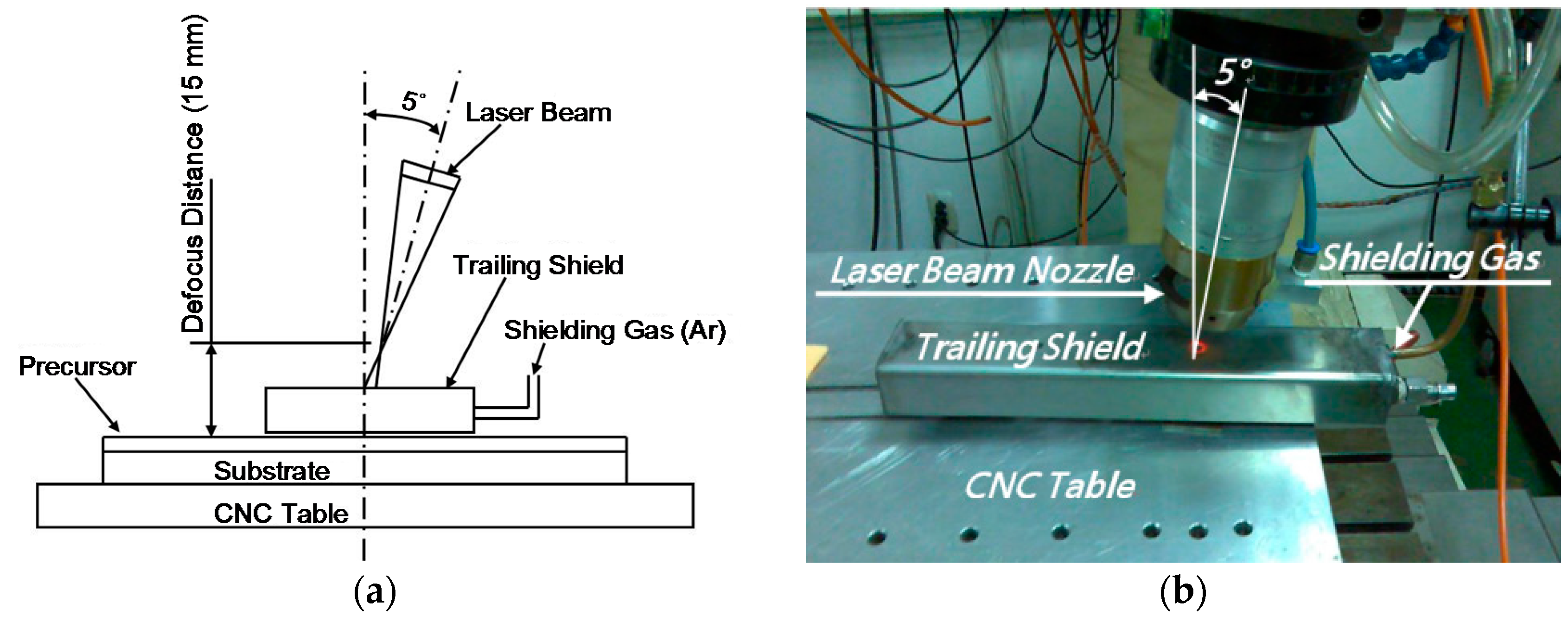
2. Experiments
3. Results and Discussion
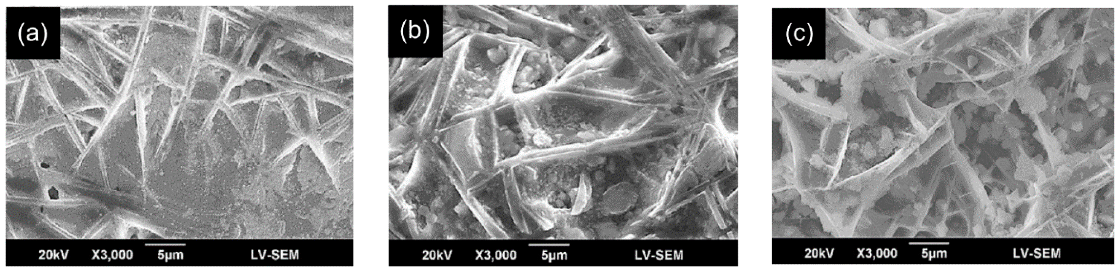
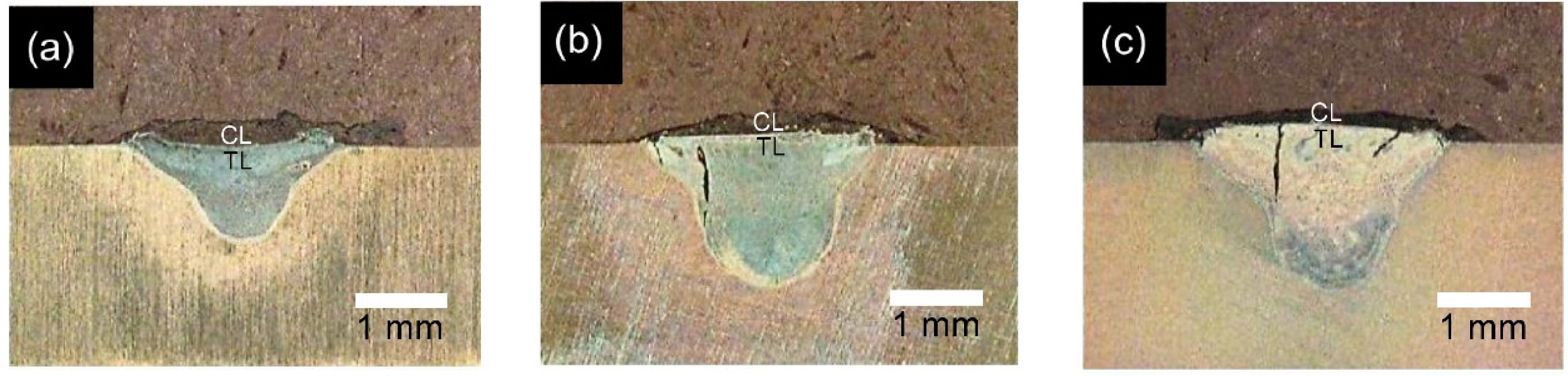
3.1. Morphology and Microstructure of Weld Beads
3.2. Chemical Composition Analysis of Laser-Clad Coatings
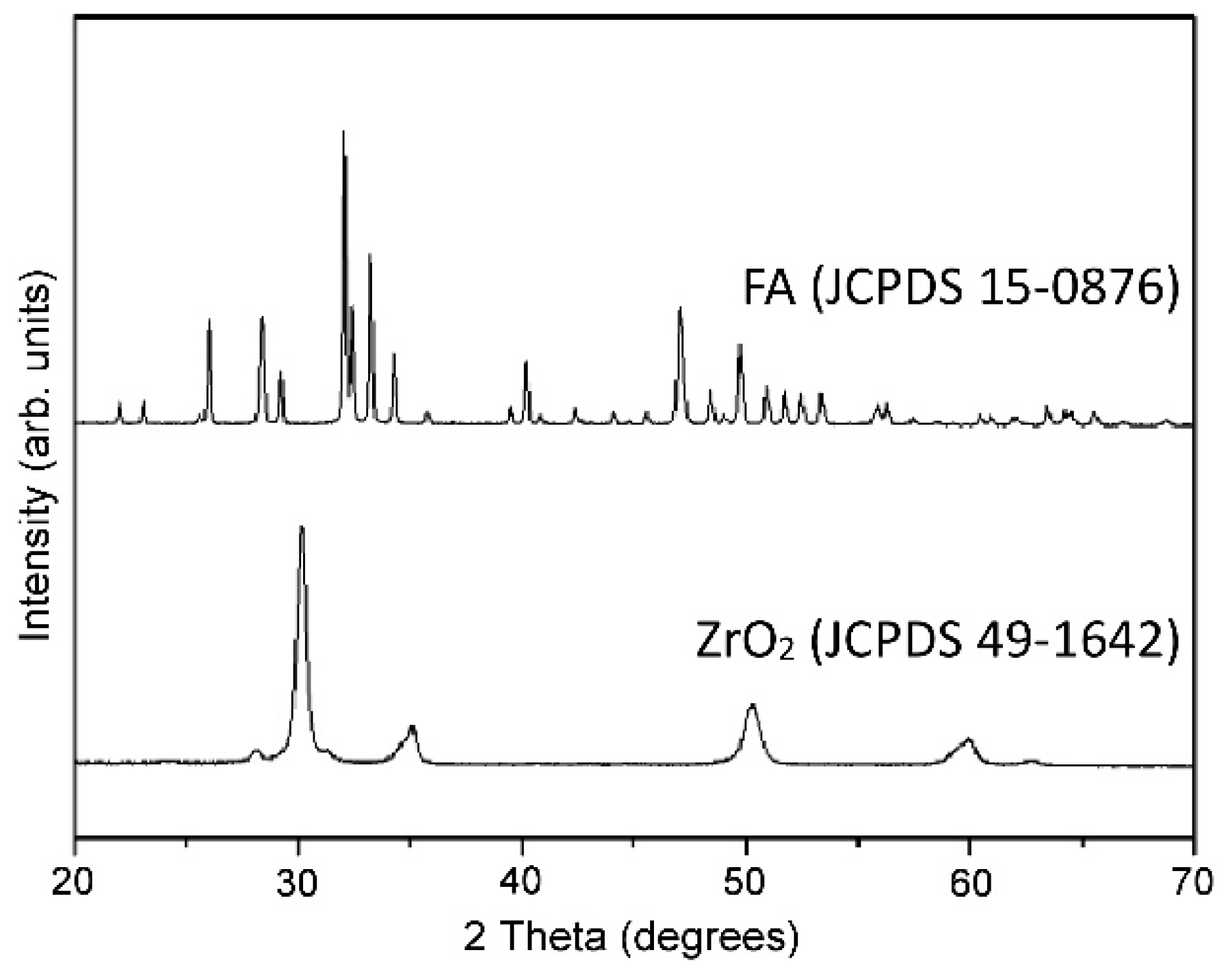
3.3. XRD Patterns of CL Surface
3.4. Micro-Hardness Evaluation
4. Conclusions
- The depth, width and depth/width ratio of the TL increase with an increasing laser power (travel speed). For the 800 W and 1200 W specimens, cracks are formed in the TL due to the greater cooling rate and larger weld zone (i.e., greater shrinkage stress). However, no cracks are formed in the CL due to the addition of ZrO2 to the FA powder and the relatively small CTE mismatch between the FA/ZrO2 powders and the substrate.
- A significant diffusion of alloying elements occurs between the CL and the TL. As a result, a good metallurgical bond is formed between them. Overall, the alloying elements of the TL are close to the composition of the substrate, while the alloying elements of the CL are close to the composition of the coating material.
- The CL of the 400 W specimen consists mainly of FA, TTCP, CaF2, CaZrO3, CaTiO3, m-ZrO2 and a small amount of θ-Al2O3. For the 800 W specimen, the CL also contains CaO, CaCO3 and trace amounts of t-ZrO2. For the highest laser power of 1200 W, the CaO, CaCO3 and TTCP contents of the CL increase significantly. The t-ZrO2 content also increases. However, that of m-ZrO2 and CaZrO3 reduces. In general, the tendency to form composite phases increases as the laser power increases.
- For all of the specimens, the TL has a greater hardness than the CL. Moreover, the CL hardness is around 2~3 times higher than that of the Ti6Al4V substrate. As the laser power increases from 400 W to 800 W, the CL hardness increases due to a microstructural refinement and densification effect. However, under the highest laser power of 1200 W, the hardness reduces significantly due to the formation of CaO and CaCO3 phases with relatively low hardness.
Acknowledgments
Author Contributions
Conflicts of Interest
References
- Zhao, Y.T.; Zhang, Z.; Dai, Q.X.; Lin, D.Y.; Li, S.M. Microstructure and bond strength of HA(+ZrO2 + Y2O3)/Ti6Al4V composite coatings fabricated by RF magnetron sputtering. Surf. Coat. Technol. 2006, 200, 5354–5363. [Google Scholar] [CrossRef]
- Wang, B.C.; Chang, E.; Yang, C.Y.; Tu, D. A histomorphometric study on osteoconduction and osseointegration of titanium alloy with and without plasma-sprayed hydroxyapatite coating using back-scattered electron images. J. Mater. Sci. Mater. Med. 1993, 4, 394–403. [Google Scholar] [CrossRef]
- Savarino, L.; Fini, M.; Ciapetti, G.; Cenni, E.; Granchi, D.; Baldini, N.; Greco, M.; Rizzi, G.; Giardino, R.; Giunti, A. Biologic effects of surface roughness and fluorhydroxyapatite coating on osteointegration in external fixation systems: An in vivo experimental study. J. Biomed. Mater. Res. A 2003, 66, 652–661. [Google Scholar] [CrossRef] [PubMed]
- Khor, K.A.; Fu, L.; Lim, V.J.P.; Cheang, P. The effects of ZrO2 on the phase compositions of plasma sprayed HA/YSZ composite coatings. Mater. Sci. Eng. A 2000, 276, 160–166. [Google Scholar] [CrossRef]
- De Bruijn, J.D.; van Blitterswijk, C.A.; Davies, J.E. Initial bone matrix formation at the hydroxyapatite interface in vivo. J. Biomed. Mater. Res. 1995, 29, 89–99. [Google Scholar] [CrossRef] [PubMed]
- Oonishi, H.; Iwaki, Y.; Kin, N.; Kushitani, S.; Murata, N.; Wakitani, S.; Imoto, K. Hydroxyapatite in revision of total hip replacements with massive acetabular defects. J. Bone Jt. Surg. 1997, 79B, 87–92. [Google Scholar] [CrossRef]
- Sun, L.; Berndt, C.C.; Gross, K.A.; Kucuk, A. Material fundamentals and clinical performance of plasma-sprayed hydroxyapatite coatings: A review. J. Biomed. Mater. Res. 2001, 58, 570–592. [Google Scholar] [CrossRef] [PubMed]
- Li, H.; Li, Z.X.; Li, H.; Wu, Y.Z.; Wei, Q. Characterization of plasma sprayed hydroxyapatite/ZrO2 graded coating. Mater. Des. 2009, 30, 3920–3924. [Google Scholar] [CrossRef]
- Wang, G.; Zreiqat, H. Review—Functional coatings or films for hard-tissue applications. Materials 2010, 3, 3994–4050. [Google Scholar] [CrossRef]
- Chen, Y.; Miao, X. Thermal and chemical stability of fluorohydroxyapatite ceramics with different fluorine contents. Biomaterials 2005, 26, 1205–1210. [Google Scholar] [CrossRef] [PubMed] [Green Version]
- Rawls, H.R.; Zimmerman, B.F. Fluoride-exchanging resins for caries for caries protection. Caries Res. 1983, 17, 32–43. [Google Scholar] [CrossRef] [PubMed]
- Bhadang, K.A.; Gross, K.A. Influence of fluorapatite on the properties of thermally sprayed hydroxyapatite coatings. Biomaterials 2004, 25, 4935–4945. [Google Scholar] [CrossRef] [PubMed]
- Weng, J.; Liu, X.; Zhang, X.; Ji, X. Thermal decomposition of hydroxyapatite structure induced by titanium and its dioxide. J. Mater. Sci. Lett. 1994, 13, 159–161. [Google Scholar] [CrossRef]
- Moreno, E.C.; Kresak, M.; Zahradnik, R.T. Fluoridated hydroxyapatite solubility and caries formation. Nature 1974, 247, 64–65. [Google Scholar] [CrossRef] [PubMed]
- Ingram, G.S.; Nash, P.F. Mechanism for the anticaries action of fluoride. Caries Res. 1980, 14, 298–303. [Google Scholar] [CrossRef] [PubMed]
- Al-Noaman, A.; Karpukhina, N.; Rawlinson, S.C.F.; Hill, R.G. Effect of FA on bioactivity of bioactive glass coating for titanium dental implant. Part I: Composite powder. J. Non-Cryst. Solids 2013, 364, 92–98. [Google Scholar] [CrossRef]
- Dhert, W.J.; Klein, C.P.; Jansen, J.A.; van der Velde, E.A.; Vriesde, R.C.; Rozing, P.M.; de Groot, K. A histological and histomorphometrical investigation of fluorapatite, magnesiumwhitlockite, and hydroxylapatite plasma-sprayed coatings in goats. J. Biomed. Mater. Res. 1993, 27, 127–138. [Google Scholar] [CrossRef] [PubMed]
- Wei, M.; Evans, J.H.; Bostrom, T.; Grøndahl, L. Synthesis and characterization of hydroxyapatite, fluoride-substituted hydroxyapatite and fluorapatite. J. Mater. Sci. Mater. Med. 2003, 14, 311–320. [Google Scholar] [CrossRef] [PubMed]
- Viswanath, B.; Ravishankar, N. Interfacial reactions in hydroxyapatite/alumina nanocomposites. Scr. Mater. 2006, 55, 863–866. [Google Scholar] [CrossRef]
- Suchanek, W.; Yoshimura, M. Processing and properties of hydroxyapatite-based biomaterials for use as hard tissue replacement implants. J. Mater. Res. 1998, 13, 94–117. [Google Scholar] [CrossRef]
- Gautier, S.; Champion, E.; Bernache-Assollant, D. Processing, microstructure and toughness of Al2O3 platelet-reinforced hydroxyapatite. J. Eur. Ceram. Soc. 1997, 17, 1361–1369. [Google Scholar] [CrossRef]
- Li, J.; Fartash, B.; Hermansson, L. Hydroxyapatite-alumina composites and bone-bonding. Biomaterials 1995, 16, 417–422. [Google Scholar] [CrossRef]
- Nasiri-Tabrizi, B.; Fahami, A. Synthesis and characterization of fluorapatite-zirconia composite nanopowders. Ceram. Int. 2013, 39, 4329–4337. [Google Scholar] [CrossRef]
- Ben Ayed, F.; Bouaziz, J. Sintering of tricalcium phosphate-fluorapatite composites with zirconia. J. Eur. Ceram. Soc. 2008, 28, 1995–2002. [Google Scholar] [CrossRef]
- Ramachandra Rao, R.; Kannan, T.S. Synthesis and sintering of hydroxyapatite-zirconia composites. Mater. Sci. Eng. C 2002, 20, 187–193. [Google Scholar] [CrossRef]
- Sallemi, I.; Bouaziz, J.; Ben Ayed, F. Elaboration and characterization of bioceramic based on tricalcium phosphate and zirconia. Int. J. Curr. Eng. Technol. 2013, 3, 1691–1700. [Google Scholar]
- Song, J.H.; Lee, J.H. Glycothermal synthesis and characterization of 3Y-TZP nanoparticles. Korean J. Mater. Res. 2009, 19, 412–416. [Google Scholar] [CrossRef]
- Subbara, E.C. Science and Technology of Zirconia; Heuer, A.H., Hobbs, A.H., Eds.; The American Society: Columbus, OH, USA, 1981; Volume 3, pp. 1–24. [Google Scholar]
- Chou, B.Y.; Chang, E.; Yao, S.Y.; Chen, J.M. Phase transformation during plasma spraying of hydroxyapatite—10-wt %-zirconia composite coating. J. Am. Ceram. Soc. 2002, 85, 661–669. [Google Scholar] [CrossRef]
- Butler, E.P. Transformation-toughened zirconia ceramics. Mater. Sci. Technol. 1985, 1, 417–432. [Google Scholar] [CrossRef]
- Nasiri-Tabrizi, B.; Fahami, A. Reaction mechanisms of synthesis and decomposition of fluorapatite-zirconia composite nanopowders. Ceram. Int. 2013, 39, 5125–5136. [Google Scholar] [CrossRef]
- Piconi, C.; Maccauro, G. Review—Zirconia as a ceramic biomaterial. Biomaterials 1999, 20, 1–25. [Google Scholar] [CrossRef]
- Tlotleng, M.; Akinlabi, E.; Shukla, M.; Pityana, S. Microstructures, hardness and bioactivity of hydroxyapatite coatings deposited by direct laser melting process. Mater. Sci. Eng. C 2014, 43, 189–198. [Google Scholar] [CrossRef] [PubMed]
- Wang, D.G.; Chen, C.Z.; Ma, J.; Lei, T.Q. Microstructure of yttric calcium phosphate bioceramic coatings synthesized by laser cladding. Appl. Surf. Sci. 2007, 253, 4016–4020. [Google Scholar] [CrossRef]
- Cheng, G.J.; Pirzada, D.; Cai, M.; Mohanty, P.; Bandyopadhyay, A. Bioceramic coating of hydroxyapatite on titanium substrate with Nd-YAG laser. Mater. Sci. Eng. C 2005, 25, 541–547. [Google Scholar] [CrossRef]
- Chien, C.S.; Hong, T.F.; Han, T.J.; Kuo, T.Y.; Liao, T.Y. Effects of different binders on microstructure and phase composition of hydroxyapatite Nd-YAG laser clad coatings. Appl. Surf. Sci. 2011, 257, 2387–2393. [Google Scholar] [CrossRef]
- Chien, C.S.; Liao, T.Y.; Hong, T.F.; Kuo, T.Y.; Chang, C.H.; Yeh, M.L.; Lee, T.M. Surface microstructure and bioactivity of hydroxyapatite and fluorapatite coatings deposited on Ti-6Al-4V substrates using Nd-YAG laser. J. Med. Biol. Eng. 2014, 34, 109–115. [Google Scholar] [CrossRef]
- Chien, C.S.; Ke, Y.S.; Kuo, T.Y.; Liao, T.Y.; Lee, T.M.; Hong, T.F. Effect of TiO2 addition on surface microstructure and bioactivity of fluorapatite coatings deposited using Nd:YAG laser. Proc. Inst. Mech. Eng. H 2014, 228, 379–387. [Google Scholar] [CrossRef] [PubMed]
- Chien, C.S.; Ke, Y.S.; Kuo, T.Y.; Liao, T.Y.; Lin, H.C.; Lee, T.M. Surface properties and in vitro bioactivity of fluorapatite/TiO2 coatings deposited on Ti substrates by Nd:YAG laser cladding. J. Med. Biol. Eng. 2015, 35, 357–366. [Google Scholar] [CrossRef]
- Chien, C.S.; Liu, C.W.; Kuo, T.Y.; Wu, C.C.; Hong, T.F. Bioactivity of fluorapatite/alumina composite coatings deposited on Ti6Al4V substrates by laser cladding. Appl. Phys. A 2016, 122. [Google Scholar] [CrossRef]
- Kim, H.W.; Kong, Y.M.; Koh, Y.H.; Kim, H.E.; Kim, H.M.; Ko, J.S. Pressureless sintering and mechanical and biological properties of fluor-hydroxyapatite composites with zirconia. J. Am. Ceram. Soc. 2003, 86, 2019–2026. [Google Scholar] [CrossRef]
- Kelkar, G. Pulsed Laser Welding; WJM Technology: Cerritos, CA, USA; Available online: http://www.welding-consultant.com (accessed on 29 July 2011).
- Ouyang, J.H.; Nowotny, S.; Richter, A.; Beyer, E. Laser cladding of yttria partially stabilized ZrO2 (YPSZ) ceramic coatings on aluminum alloys. Ceram. Int. 2001, 27, 15–24. [Google Scholar] [CrossRef]
- Song, W.; Zhu, P.; Cui, K. Effect of Ni content on cracking susceptibility and microstructure of laser-clad Fe-Cr-Ni-B-Si alloy. Surf. Coat. Technol. 1996, 80, 279–282. [Google Scholar]
- Zhang, S.; Zeng, X.; Wang, Y.; Cheng, K.; Weng, W. Adhesion strength of sol-gel derived fluoridated hydroxyapatite coatings. Surf. Coat. Technol. 2006, 200, 6350–6354. [Google Scholar] [CrossRef]
- Scardi, P.; Leoni, M.; Bertamini, L. Residual stresses in plasma sprayed partially stabilized zirconia TBCs: Influence of the deposition temperature. Thin Solid Films 1996, 278, 96–103. [Google Scholar] [CrossRef]
- Zheng, X.B.; Ding, C.X. Characterization of plasma sprayed hydroxyapatite/TiO2 composite coatings. J. Therm. Spray Technol. 2000, 9, 520–525. [Google Scholar] [CrossRef]
- Ye, H.; Liu, X.Y.; Hong, H. Fabrication of titanium/fluorapatite composites and in vitro behavior in simulated body fluid. J. Mater. Sci. Technol. 2013, 29, 523–532. [Google Scholar] [CrossRef]
- Ninga, C.Q.; Zhoub, Y. On the microstructure of biocomposites sintered from Ti, HA and bioactive glass. Biomaterials 2004, 25, 3379–3387. [Google Scholar] [CrossRef] [PubMed]
- Ben Ayed, F.; Bouaziz, J.; Bouzouita, K. Calcination and sintering of fluorapatite under argon atmosphere. J. Alloys Compd. 2001, 322, 238–245. [Google Scholar] [CrossRef]
- Nagarajan, V.S.; Rao, K.J. Structural, mechanical and biocompatibility studies of hydroxyapatite-derived composites toughened by zirconia addition. J. Mater. Chem. 1993, 3, 43–51. [Google Scholar] [CrossRef]
- Heimann, R.B.; Vu, T.A. Effect of CaO on thermal decomposition during sintering of composite hydroxyapatite-zirconia mixtures for monolithic bioceramic implants. J. Mater. Sci. Lett. 1997, 16, 437–439. [Google Scholar] [CrossRef]
- Wu, J.M.; Yeh, T.S. Sintering of hydroxyapatite-zirconia composite materials. J. Mater. Sci. 1988, 23, 3771–3777. [Google Scholar] [CrossRef]
- Stubican, V.S.; Ray, S.P. Phase equilibria and ordering in the system ZrO2-CaO. J. Am. Ceram. Soc. 1977, 60, 534–537. [Google Scholar] [CrossRef]
- Li, J.; Chen, C. Effect of ZrO2 (YPSZ) on microstructure characteristic and wear resistance of theTi3Al/TiC laser-cladded ceramic layer on titanium alloy. Int. J. Appl. Ceram. Technol. 2012, 9, 947–952. [Google Scholar] [CrossRef]
- Hardness of Minerals Va: Variation among Oxides and Oxysalts. Available online: http://www.gly.uga.edu/railsback/Fundamentals/HardnessTrends29VaL.pdf (accessed on 29 January 2008).
- Chien, C.S.; Liao, T.Y.; Hong, T.F.; Kuo, T.Y.; Wu, J.L.; Lee, T.M. Investigation into microstructural properties of fluorapatite Nd-YAG laser clad coatings with PVA and WG binders. Surf. Coat. Technol. 2011, 205, 3141–3146. [Google Scholar] [CrossRef]


| Al | V | O | Fe | C | N | H | Ti |
|---|---|---|---|---|---|---|---|
| 6.1 | 4.24 | 0.152 | 0.16 | 0.017 | 0.008 | 0.0006 | Balance |
| Sample | 400 W/200 mm/min | 800 W/400 mm/min | 1200 W/600 mm/min |
|---|---|---|---|
| Depth (mm) | 1.1 | 1.8 | 2.0 |
| Width (mm) | 2.5 | 2.9 | 3.1 |
| Depth/Width Ratio | 0.44 | 0.62 | 0.65 |
© 2016 by the authors; licensee MDPI, Basel, Switzerland. This article is an open access article distributed under the terms and conditions of the Creative Commons Attribution (CC-BY) license (http://creativecommons.org/licenses/by/4.0/).
Share and Cite
Chien, C.-S.; Liu, C.-W.; Kuo, T.-Y. Effects of Laser Power Level on Microstructural Properties and Phase Composition of Laser-Clad Fluorapatite/Zirconia Composite Coatings on Ti6Al4V Substrates. Materials 2016, 9, 380. https://doi.org/10.3390/ma9050380
Chien C-S, Liu C-W, Kuo T-Y. Effects of Laser Power Level on Microstructural Properties and Phase Composition of Laser-Clad Fluorapatite/Zirconia Composite Coatings on Ti6Al4V Substrates. Materials. 2016; 9(5):380. https://doi.org/10.3390/ma9050380
Chicago/Turabian StyleChien, Chi-Sheng, Cheng-Wei Liu, and Tsung-Yuan Kuo. 2016. "Effects of Laser Power Level on Microstructural Properties and Phase Composition of Laser-Clad Fluorapatite/Zirconia Composite Coatings on Ti6Al4V Substrates" Materials 9, no. 5: 380. https://doi.org/10.3390/ma9050380