Article

Optimization Design by Genetic Algorithm Controller for Trajectory Control of a 3-RRR Parallel Robot

School of Mechatronic Engineering, China University of Mining and Technology, Xuzhou 221116, China
*
Author to whom correspondence should be addressed.
Algorithms 2018, 11(1), 7; https://doi.org/10.3390/a11010007
Submission received: 21 November 2017 / Revised: 30 December 2017 / Accepted: 12 January 2018 / Published: 15 January 2018
(This article belongs to the Special Issue Algorithms for PID Controller)

Abstract

:
In order to improve the control precision and robustness of the existing proportion integration differentiation (PID) controller of a 3-Revolute–Revolute–Revolute (3-RRR) parallel robot, a variable PID parameter controller optimized by a genetic algorithm controller is proposed in this paper. Firstly, the inverse kinematics model of the 3-RRR parallel robot was established according to the vector method, and the motor conversion matrix was deduced. Then, the error square integral was chosen as the fitness function, and the genetic algorithm controller was designed. Finally, the control precision of the new controller was verified through the simulation model of the 3-RRR planar parallel robot—built in SimMechanics—and the robustness of the new controller was verified by adding interference. The results show that compared with the traditional PID controller, the new controller designed in this paper has better control precision and robustness, which provides the basis for practical application.

1. Introduction

Parallel industrial robots are essentially closed kinematic chain mechanisms, in which the end-effector is clamped onto the base through several independent kinematic chains [1]. Parallel industrial robots exhibit the following obvious advantages over the serial series: no cumulative error, little movement inertia, high structural stiffness, high load capacity, and so on. They are suitable for fast and accurate operations, and have been widely applied in industrial fields such as integrated circuit manufacturing and testing, fiber docking, and flight simulators [2,3]. For instance, Lee and Yien [4] set up a three degrees of freedom (3-DOF) parallel industrial robot in order to operate and carry large-scale workpieces. Another 3-DOF micro-sized planar parallel industrial robot was developed for low-torque precision positioning tasks [5]. Combined with the advantages of parallel robots and their wide applications in all aspects of social life, the research on parallel industrial robots is of great significance.
A typical 3-DOF planar 3-Revolute–Revolute–Revolute (3-RRR) parallel industrial robot—consisting of a moving platform which is connected to three identical branches and a static platform—has the advantages of a simple structure, good symmetry and accurate positioning. Therefore, many scholars have conducted detailed research on it. Gutierrez [6] performed an exhaustive singularity analysis of a 3-RRR planar parallel robot. From a kinematic point of view, the optimum characteristics of the 3-DOF planar parallel industrial robot were studied by Gosselin and Angeles [7]. Serdar Kucuk [8] presented an optimization problem for the 3-degrees-of-freedom RRR fully planar parallel manipulator (3-RRR) based on the actuator power consumption. The effects of clearance on the dynamics of a planar 3-RRR parallel manipulator are investigated in [9]. Based on forward kinematics theory, Flavio and Ron [10] studied the singularity problem, focusing completely on the planar parallel robot. Sébastien and Ilian [11] studied the accuracy problems on several kinds of typical 3-DOF planar parallel industrial robots. Gao [12] designed a planar 3-RRR parallel industrial robot by analyzing kinematics, singularity, dynamics, and controlling problems. Zhang et al. [13] presented the first-order approximation coupling model of planar 3-RRR flexible parallel robots and considered the rigid body motion constraints, elastic deformation motion constraints, and dynamic constraints of the moving platform in the coupling model. Yu [14] presented experimental research on the dynamics of flexible 3-RRR parallel robots and compared the results between the theoretical and experimental analysis. It can be seen from the above literature that the current research on the 3-RRR parallel robot mainly focuses on the dynamics model, work space analysis, singular point analysis, and structural optimization. Good control precision also plays a crucial role in the practical application of a robot.
At present, the research on robot control algorithms mainly focuses on fuzzy control algorithms [15], adaptive robust control algorithms [16], and genetic control algorithms [17]. Stanet et al. [18] proposed a fuzzy controller for a 3-DOF parallel industrial robot in medical applications, and achieved more precise results with the fuzzy-based controller than with the classic PID controller. Noshadi et al. [19,20] introduced a method by which an active force can be used to control the platform. They also designed a two-level fuzzy tuning resolved acceleration control for the platforms. In doing so, they suggested that when there is disturbance, the manipulator can still perform trajectory tracking tasks with a stable response. Pham et al. [21] proposed a robust adaptive control method based on radial basis function neural network (RBFNN), and studied the trajectory tracking control of a two-link robot cleaning detection mechanism. In research by Ku et al. [22] the model predictive control was performed to fulfill the positioning control of a 3-RRR planar parallel manipulator. Song et al. [23] proposed a new path planning method for a robot based on a genetic algorithm and the Bezier curve. Wang et al. [24] presented a double global optimum genetic algorithm–particle swarm optimization for path planning of a welding robot. Lu et al. [25,26] proposed a new method for the optimal design and tuning of a Proportional–Integral–Derivative-type interval type-2 fuzzy logic controller for Delta parallel robot trajectory tracking control. The main aims of the above literature are to improve the robot control accuracy. However, a good control program needs to not only improve the control accuracy but also have the characteristics of simplicity, applicability, robustness, and stability.
It is well known that the classic PID controllers have the advantage of simplicity, and the genetic random search algorithm has a fast search ability. A variable PID parameter controller optimized by a genetic algorithm has been designed in this paper, differing from previous research by combining both advantages. The inverse kinematics model of the 3-RRR parallel robot was established according to the vector method, and the motor conversion matrix was deduced. The control precision of the new controller was verified through the simulation model of the 3-RRR planar parallel robot—built in SimMechanics—and the robustness of the new controller was verified by adding interference. The results show that compared with the traditional PID controller, the new controller designed in this paper not only has better control precision, stability, and higher robustness but also has the characteristics of simplicity and applicability, which provides the basis for practical application. The other parts of this paper are arranged as follows: Section 2 introduces the model of the planar parallel industrial robot; Section 3 presents the virtual bench setup and genetic algorithm controller; Section 4 discusses the simulation results; finally, Section 5 is the conclusion.

2. The Model of the Planar 3-RRR Parallel Robot

It is essential to establish the kinematics model for researching the planar parallel industrial robot control strategies. In this section, the inverse kinematics model of the 3-RRR parallel robot is established according to the vector method, and the motor conversion matrix is deduced, which is the foundation for the subsequent control.

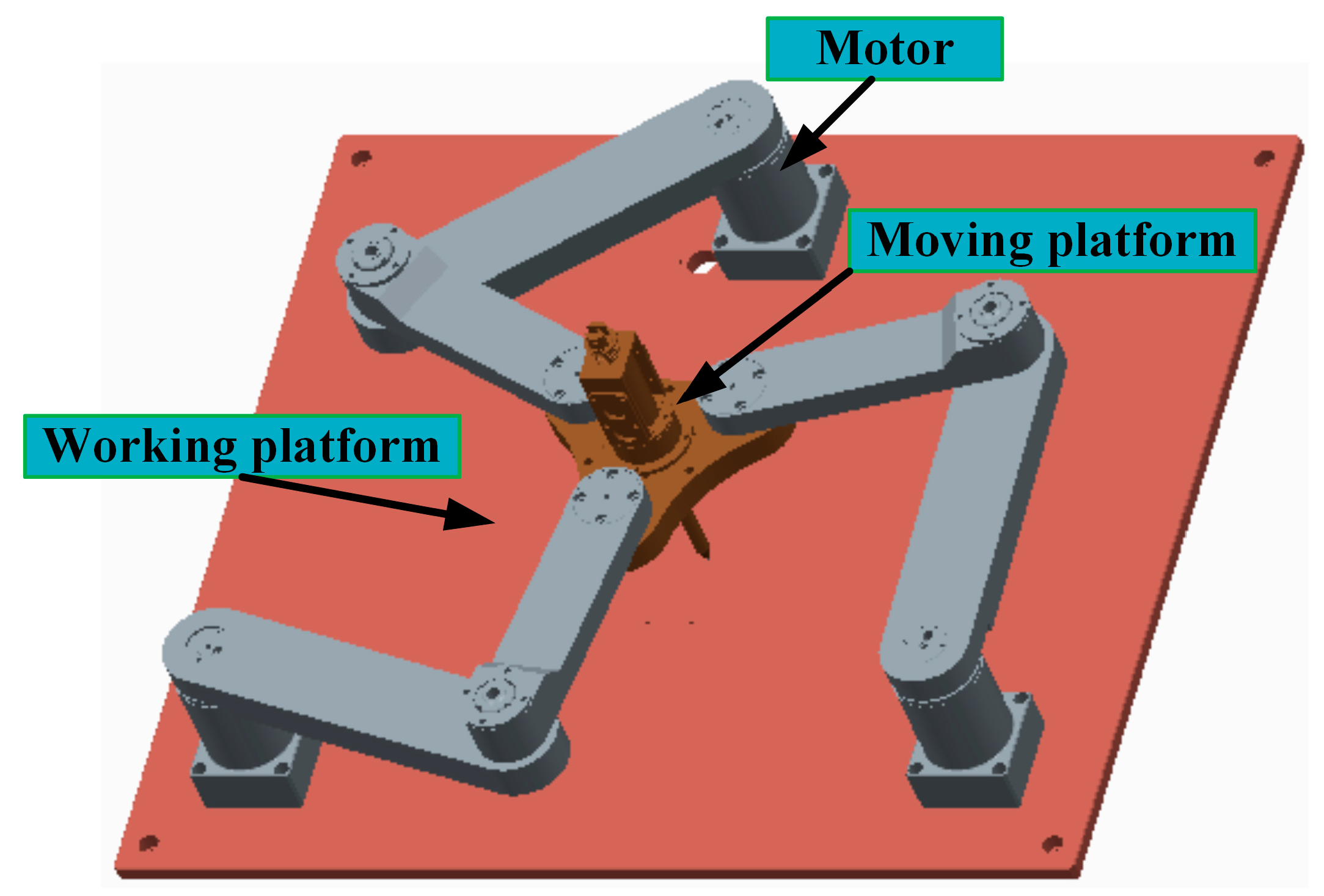
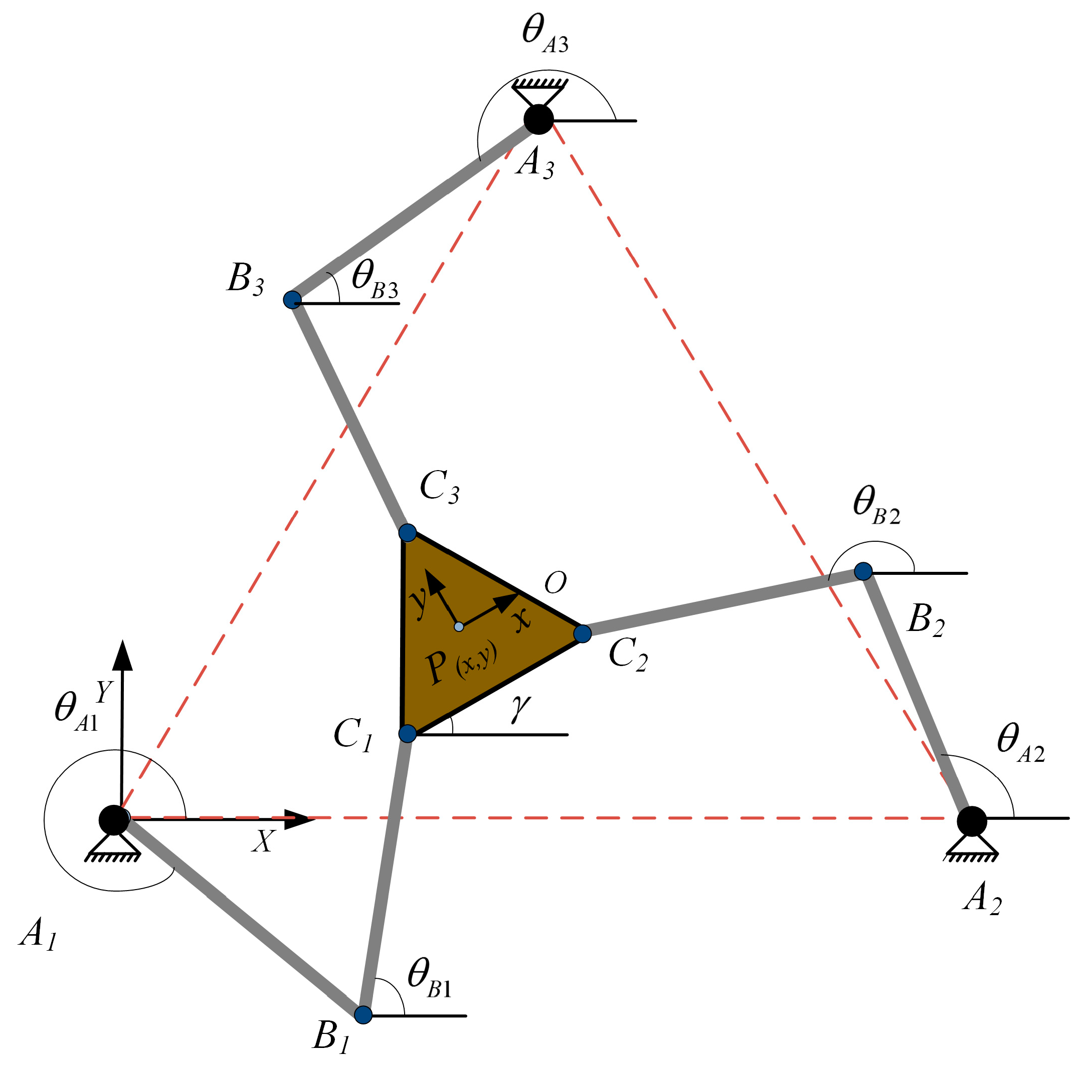
2.1. The Structure of the 3-RRR Planar Parallel Robot

The three-dimensional map of the 3-RRR parallel robot is shown in Figure 1. The schematic diagram of the 3-RRR planar parallel robot is shown in Figure 2. The outline of the 3-RRR planar parallel robot is composed of the regular triangle of the moving platform C1C2C3; the fixed base A1A2A3; and three identical branches A1B1C1, A2B2C2, A3B3C3. As Figure 2 shows, the three vertices of the regular triangle are A1, A2, A3, where the active revolute joints are set. The points of B1, C1, B2, C2, B3, C3 are the passive revolute joints, where A1B1 = A2B2 = A3B3 = l1, B1C1 = B2C2 = B3C3 = l2. The radius of the circle of the motor in the working platform is R. The radius of the circle of the joints in the moving platform is r. The 3-DOF planar motion can be achieved using the three driving motors in the three active joints.

2.2. The Kinematic Model of the 3-RRR Planar Parallel Robot

According to the geometric relationships shown in Figure 2, the coordinates of the motor in the static coordinate system are shown as follows,
A = [ A 1 A 2 A 3 ] = [ 0 3 R 3 2 R 0 0 3 2 R ]
The coordinates of the center of the moving platform in the moving coordinate system are shown as follows,
P = [ C 1 C 2 C 3 ] = [ 3 2 r 3 2 r 0 1 2 r 1 2 r r ]
The spatial transformation matrix T for transforming the moving coordinate system into the static coordinate system is shown as follows,
T = [ cos β cos γ sin β cos γ sin α sin γ cos α sin β cos γ cos α + sin γ sin α x sin γ cos β sin γ sin β sin α + cos γ cos α sin γ sin β cos α cos γ sin α y sin β cos β sin α cos β cos α z 0 0 0 1 ]
where α , β , γ are the rotation angles around X, Y and Z, respectively. x, y, z are the distances along the X, Y and Z axes, respectively. Due to the parallel robot studied in this paper, they can only be translated along the x, y axis and rotated around the z axis,
α   =   0 , β   =   0 , z   =   0
T can be expressed as follows,
T = [ cos γ sin γ 0 x sin γ cos γ 0 y 0 0 1 0 0 0 0 1 ]
The coordinates of the moving platform center in the static coordinate system can be expressed as follows,
[ C 1 ] = T × [ P 1 ]
Combining Equations (2) and (5), C can be expressed as follows,
C = [ C 1 C 2 C 3 ] = [ x r cos ( π 6 γ ) x + r cos ( γ π 6 ) x r sin γ y r sin ( π 6 + γ ) y + r sin ( γ π 6 ) y + r cos γ ]
For any one branch AiBiCi, the parallel robot satisfies the following motion constraint of the closed-loop vector. The vector equation is expressed as follows [8],
O C i = O A i + A i B i + B i C i
where i = 1, 2, 3.
Combined with Equation (8), θ B i is the angle between the link BiCi and the positive direction of the X axis.
{ x C i = x A i + l 1 cos θ A i + l 2 cos θ B i y C i = y A i + l 1 sin θ A i + l 2 sin θ B i
Equation (9) can be expressed as follows,
f i 1 sin θ A i + f i 2 cos θ A i + f i 3 = 0
where
f i 1 = 2 l 1 ( y A i y C i ) f i 2 = 2 l 1 ( x A i x C i ) f i 3 = x C i 2 + y C i 2 + x A i 2 + y A i 2 2 x C i x A i 2 y C i y A i + l 1 2 l 2 2
Let t i = tan ( θ i / 2 ) , substituting Equation (10), according to the universal formula of the trigonometric function, Equation (10) can be expressed as follows,
( f i 3 f i 2 ) t i 2 + 2 f i 1 t i + ( f i 3 + f i 2 ) = 0
According to the rooting formula, the roots can be expressed as follows,
{ θ A i 1 = 2 arctan ( f i 1 + f i 1 2 + f i 2 2 f i 3 2 f i 3 f i 2 ) θ A i 2 = 2 arctan ( f i 1 f i 1 2 + f i 2 2 f i 3 2 f i 3 f i 2 )
Similarly, θ B i can be obtained.
In order to build the genetic algorithm controller, it is necessary to obtain the transformation matrix of the motor physical model. The physical model of the three-phase asynchronous motor is shown in Figure 3.
The model of the three-phase asynchronous motor can be established by coordinate transformation. The transformation matrix from the three-phase coordinate system to the two-phase stationary coordinate system through the geometric relationship can be expressed as follows [27],
C 3 s / 2 s = 2 3 [ 1 1 2 1 2 0 3 2 3 2 ]
The transformation matrix from the two-phase stationary coordinate system to the two-phase rotation coordinate system can be expressed as follows [27],
C 2 s / 2 r = [ cos θ e sin θ e sin θ e cos θ e ]

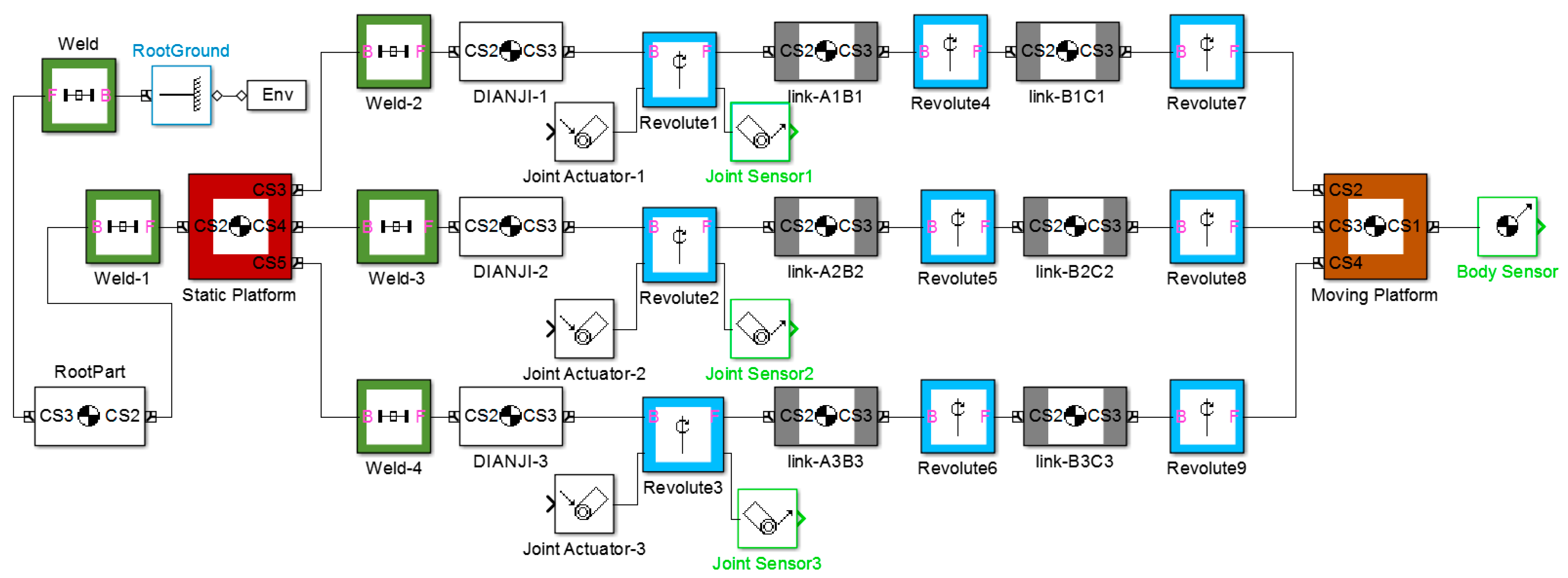
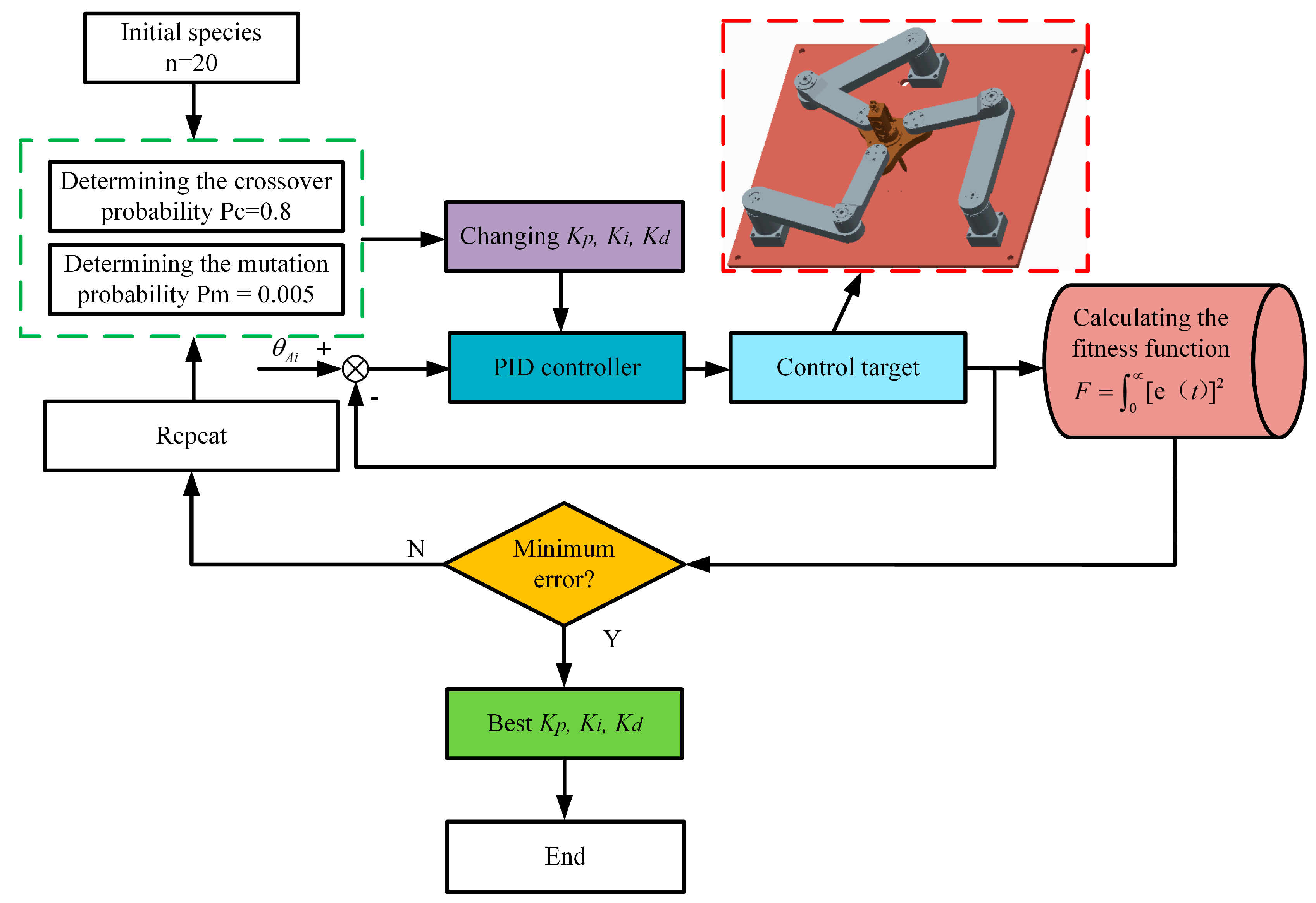
3. Virtual Bench Setup and Genetic Algorithm Controller

To verify the control effect of the PID controller optimized by the genetic algorithm, a virtual bench is constructed in SimMechanics. At the same time, to simulate the gap error between the two revolute joints in the actual system in the establishment of a three-dimensional model, the axis distance between the two revolute joints is set to 0.5 mm. As Figure 4 shows, the virtual bench of the planar 3-RRR parallel industrial robot is translated from its Pro/E form into Simulink in the SimMechanics toolbox.
According to the industrial robot structure in Figure 1, a virtual bench can be established as shown in Figure 4. The parallel industrial robot is composed of three elements, six links, one moving platform, and three driving joints. The moving platform is connected by three branches which consist of two individual links. Each of the two links are connected by revolute joints. The three driving joints on the static platform can constitute an equilateral triangle. Similarly, the three connection joints on the moving platform can also constitute an equilateral triangle.
The control scheme is significant for achieving the good stability and precise positioning needed by the 3-RRR planar parallel industrial robot. As we already know, the traditional PID controllers have good control of linear objects and their great advantages are simplicity and convenience. However, when the control reference is complicated in the trajectory tracking control, or when the dynamical parameters are changeable and complex, the classic PID control may not rapidly present a good result. In order to make the controller perform better, the genetic algorithm is introduced in this paper. It is a random search algorithm of natural selection and genetic mechanism which possesses the advantage of simplicity, versatility, robustness, and speed compared to the conventional method. The design flow chart of the genetic algorithm controller is shown in Figure 5.
The design process of the genetic algorithm is as follows:
Step 1:
Parameter encoding: Due to the need-tuning parameters in the real domain, the simple binary encoding and encoder, six sub-strings can be used as the six parameters influencing each other. They then formed a chromosome. The precision of the PID solution parameters is set to 4 digits after the decimal point, and the solution space of the PID parameters can be divided into (1000 − 0) × (104) = 10,000,000 points. Because 223 < 10,000,000 < 224, 24-bit binary numbers are needed to represent these solutions. In other words, a solution code is a 24-bit binary string. Initially, these binary strings are randomly generated. One such binary string represents a chromosome string where the length of the chromosome string is 24.
Step 2:
The fitness function is the basis for evaluating the selection, where the error integral can be used as the performance of the system, such as Integrator Error (IE), Integrator Absolute Error (IAE), Integral Square Error (ISE), Integration Time and Absolute Error (ITAE), etc. Each formula has its own focus. This paper wants to achieve a smaller dynamic error, so the integral square error is used as the fitness function:
F = 0 [ e   ( t ) ] 2
Step 3:
Genetic algorithm parameters: Group size n = 20, Crossover probability Pc = 0.8, Mutation probability Pm = 0.005.
Step 4:
If the error is minimum, then running is stopped, as the output has reached the optimal parameters. Otherwise, Steps 1 to 3 are repeated.
The stability of the controller is of great importance to the reliability of the control system. To further theoretically analyze the stability of the PID controller optimized by a genetic algorithm for the 3-RRR parallel robot, the Routh stability criterion is introduced for stability verification of the PID controller optimized by a genetic algorithm. The system PID closed-loop control block diagram is shown in Figure 6.
According to the closed-loop PID control block diagram shown in Figure 6, the characteristic equation of the closed-loop control transfer function can be expressed as follows,
b K p K d s 3 + ( b K p + a K p K d ) s 2 + ( a K p + b K p K i ) s + a K p K i = 0
The Routh-table of the characteristic equation is expressed as follows,
s 3 b K p K d a K p + b K p K i s 2 b K p + a K p K d a K p K i s 2 ( b K p + a K p K d ) ( a K p + b K p K i ) ( b K p K d ) ( a K p K i ) b K p + a K p K d s 0 a K p K i
In order to build PID controllers conveniently, the circular equation is divided into two input equations ( X P = 0.03 0.03 cos ( 50 t ) (Equation (a)), Y P = 0.03 sin ( 50 t ) (Equation (b))). Therefore, two PID controllers optimized by a genetic algorithm are set. The parameters in system transfer function are given as a = 0.7374, b = 0.000036.
When there is no interference added, the PID control parameters of the PID controller optimized by a genetic algorithm for Equation (Equation (a)) are Kp1 = 991.1899, Ki1 = 152.2033, Kd1 = 9.9589. The PID control parameters of the PID controller optimized by a genetic algorithm for Equation (Equation (b)) are Kp2 = 0.3, Ki2 = 799.9985, Kd2 = 0.0003.
When there is interference added, the PID control parameters of the PID controller optimized by a genetic algorithm for Equation (Equation (a)) are Kp1 = 100, Ki1 = 198.9589, Kd1 = 9.7398. The PID control parameters of the PID controller optimized by a genetic algorithm for Equation (Equation (b)) are Kp2 = 0.3, Ki2 = 799.4141, Kd2 = 0.0003.
Substituting the above parameters into the Routh-table Equation (17), it can be seen that none of the coefficients of the eigenvalue equation is zero, and the sign of each coefficient is positive; therefore, according to the Routh stability criterion, the system can be proved to be stable.

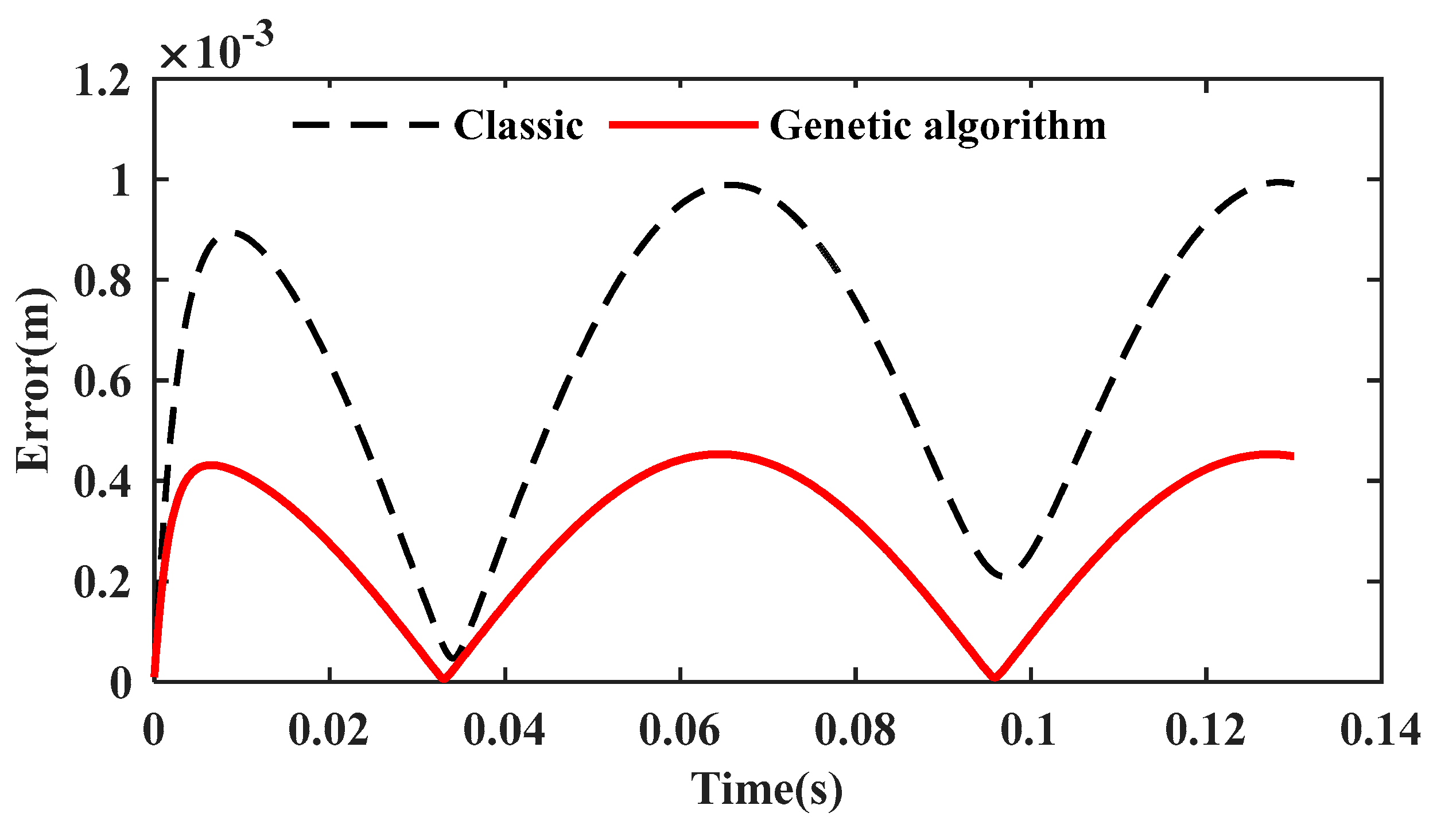
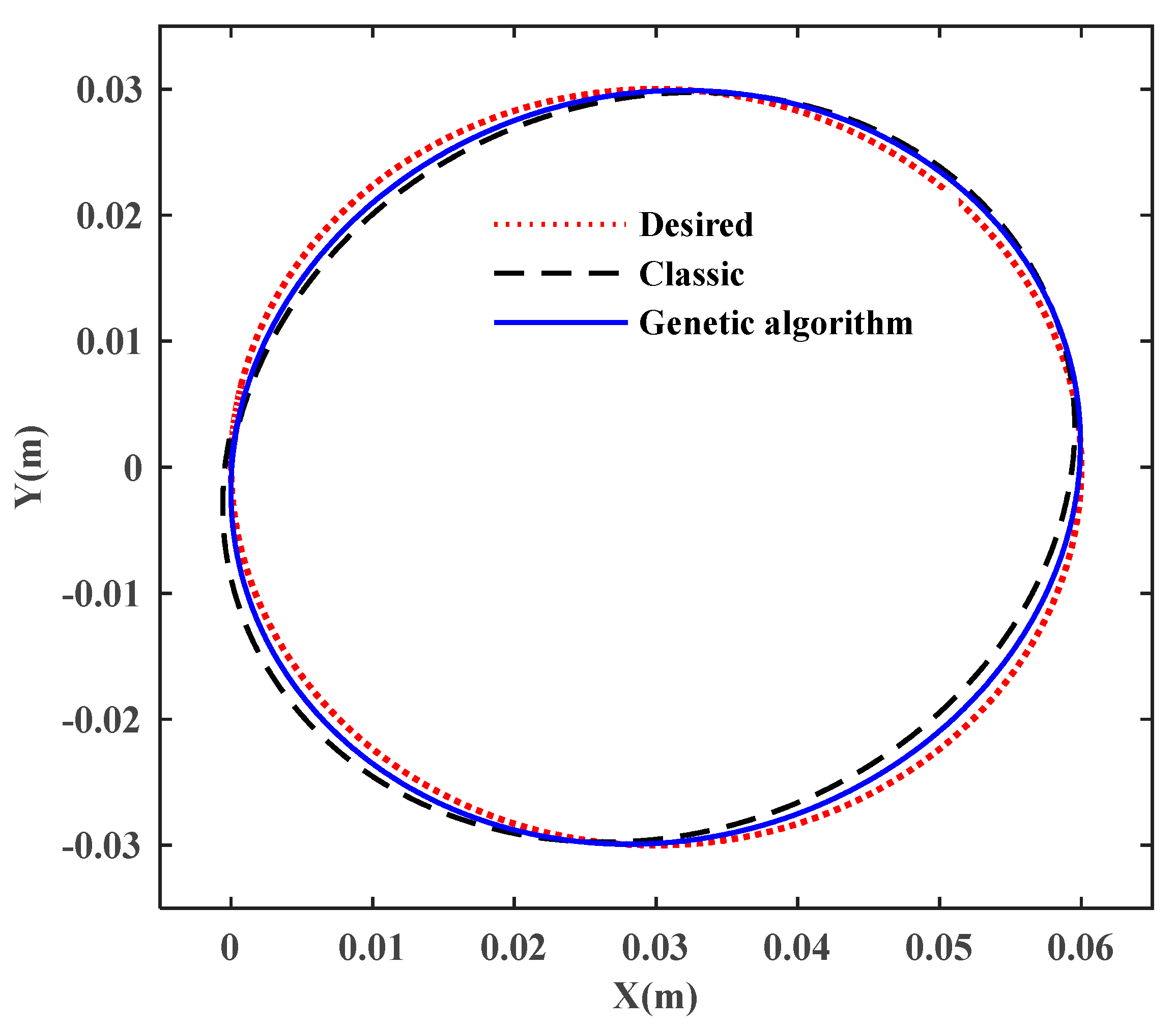
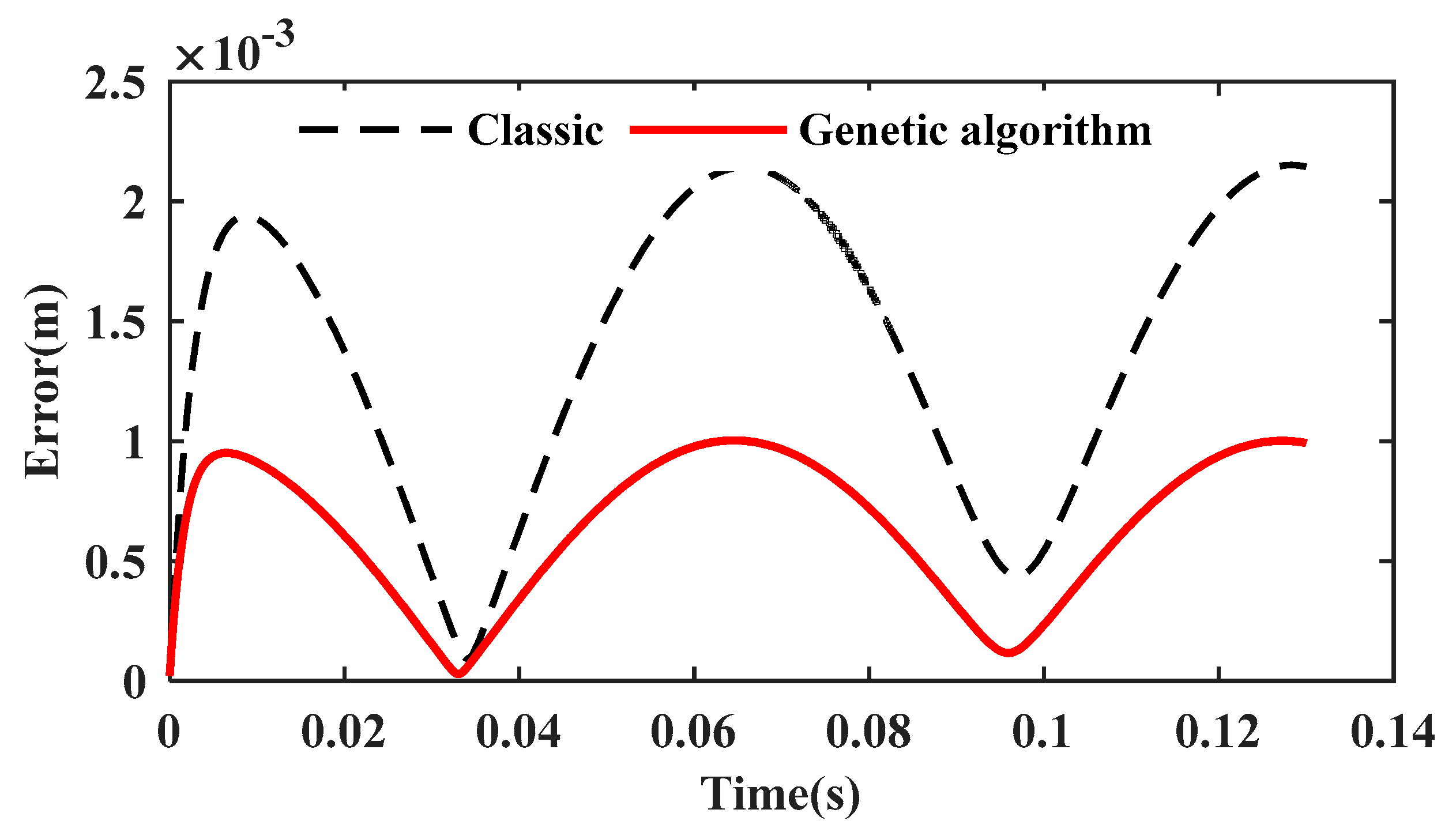
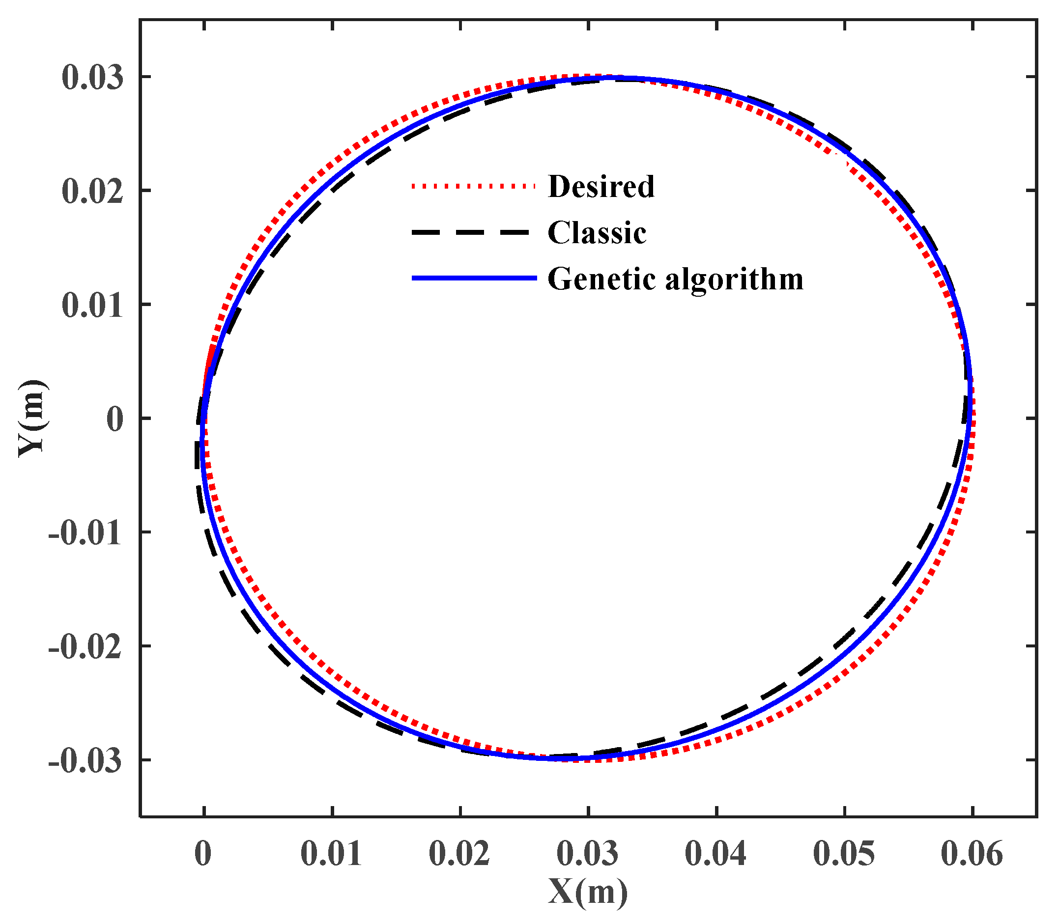
4. Simulation and Results Discussion

To verify the control effect of the PID controller optimized by a genetic algorithm, the circular trajectory which is commonly used in industrial applications is selected as the trajectory. The system control block diagram is shown in Figure 7. The trajectory equation is as follows,
X P = 0.03 0.03 cos ( 50 t ) Y P = 0.03 s in ( 50 t ) θ = π / 6
The radius of the circle where the active revolute joints are located is R = 0.25 m. The radius of the circle where the triangle of the mobile platform is located is r = 0.0825 m; the length of the links l1 = l2 = 0.16 m; the concentrated mass of the links mg = 0.2 kg; the concentrated mass of the moving platform mp = 1 kg. To better describe the trajectory tracking error, ei (i = 1, 2) are defined as the tracking errors. The control parameters of the classic PID controller are Kp1 = 10, Ki1 = 100, Kd1 = 5, Kp2 = 0.35, Ki2 = 500, Kd2 = 0.0003.
{ e 1 = ( x p x d ) 2 + ( y p y d ) 2 e 2 = ( x g x d ) 2 + ( y g y d ) 2
where
  • xd is the x coordinate of the desired trajectory.
  • yd is the y coordinate of the desired trajectory.
  • xp is the x coordinate of the trajectory obtained by the classic PID controller.
  • yp is the y coordinate of the trajectory obtained by the classic PID controller.
  • xg is the x coordinate of the trajectory obtained by the PID controller optimized by a genetic algorithm.
  • yg is the y coordinate of the trajectory obtained by the PID controller optimized by a genetic algorithm.
The trajectory tracking errors of the classic PID and the PID optimized by a genetic algorithm are shown in Figure 8. It is found that the PID controller optimized by the genetic algorithm has a higher control accuracy. The trajectories of the end-effector using the classic PID and the PID optimized by a genetic algorithm are shown in Figure 9. It can be found that the running trajectory of the PID controller optimized by a genetic algorithm is closer to the desired trajectory; therefore, the genetic algorithm-optimized PID controller designed in this paper has a higher trajectory tracking accuracy. Moreover, the PID controller obtained by a genetic algorithm saves more time than the PID controller obtained by the trial and error method, which is simple and practical.
To further verify the robustness of the controller designed in this paper, an artificial disturbance is added to the model. The curve of the disturbance is as follows:
x d = 0.003 cos ( 50 t ) y d = 0.003 sin ( 50 t )
The trajectory tracking errors of the classic PID and the PID optimized by a genetic algorithm are shown in Figure 10. The maximum error is still less than 1 mm. It is found that the controller designed in this paper still has a higher accuracy when the interference is added. The trajectories of the end-effector using the classic PID and the PID optimized by a genetic algorithm are shown in Figure 11. It can be found that the running trajectory of the PID controller optimized by a genetic algorithm is closer to the desired trajectory. Therefore, the genetic algorithm-optimized PID controller designed in this paper has a higher trajectory tracking accuracy and has better robustness when the interference is added.
Figure 12 shows the torque curves produced by the classic PID controller and the PID controller optimized by a genetic algorithm. These torque curves are measured using a torque transducer built in SimMechanics. It can be found that, compared with the traditional PID controller, the torque curves produced by the PID controller optimized by a genetic algorithm are smoother at the beginning of operation; therefore, the new controller has better stability at the beginning.

5. Conclusions

In this paper, a variable PID parameter controller optimized by a genetic algorithm controller is proposed. The inverse kinematics model of the 3-RRR parallel robot was established according to the vector method, and the motor conversion matrix was deduced. The gap error between the two revolute joints in the actual system was simulated by the establishment of a three-dimensional model; the axis distance between the two revolute joints was set to 0.5 mm. The simulation model of the 3-RRR planar parallel robot—built by SimMechanics—was used to verify the new controller. The results show that, compared with the traditional PID controller, the new controller designed in this paper has better control precision, and when interference is added to the system, the new controller has better robustness and stability, which provides the basis for practical application.

Acknowledgments

This work is supported by the National Natural Science Foundation of China (Grant No. U1610111 and No. 51775543), and the Project Funded by the Priority Academic Program Development of Jiangsu Higher Education Institutions (PAPD).

Author Contributions

Wei Li and Lianchao Sheng put forward the initial ideas; Lianchao Sheng conceived and designed the simulations model; Lianchao Sheng analyzed the data; Lianchao Sheng wrote the paper.

Conflicts of Interest

The authors declare no conflict of interest.

References

  1. Merlet, J.P. Parallel Robots; Kluwer Academic Publishers: Norwell, MA, USA, 2000. [Google Scholar]
  2. Salas, F.G.; Santibáñez, V.; Llama, M.A. Fuzzy-Tuned PD Tracking Control of a 3-RRR Parallel Manipulator: Stability Analysis and Simulations. Intell. Autom. Soft Comput. 2014, 20, 159–182. [Google Scholar] [CrossRef]
  3. Fichter, E.F. A Stewart Platform-Based Manipulator: General Theory and Practical Construction. Int. J. Robot Res. 1986, 5, 157–182. [Google Scholar] [CrossRef]
  4. Lee, K.M.; Yien, C. Design and control of a prototype platform manipulator for work holding and work handling applications. J. Mech. Work. Technol. 1989, 20, 305–314. [Google Scholar] [CrossRef]
  5. Wang, R.; Zhang, X. Parameters optimization and experiment of a planar parallel 3-dof nanopositioning system. IEEE Trans. Ind. Electron. 2017, 99, 2388–2396. [Google Scholar] [CrossRef]
  6. Gutierrez, M.N.C. Dimensional synthesis of 3rrr planar parallel robots for well-conditioned workspace. IEEE Lat. Am. Trans. 2015, 13, 409–415. [Google Scholar] [CrossRef]
  7. Gosselin, C.; Angeles, J. The optimum kinematic design of a planar three-degree-of-freedom parallel manipulator. J. Mech. Trans. Autom. Design 1988, 110, 35–41. [Google Scholar] [CrossRef]
  8. Kucuk, S. Energy minimization for 3-rrr fully planar parallel manipulator using particle swarm optimization. Mech. Mach. Theory 2013, 62, 129–149. [Google Scholar] [CrossRef]
  9. Varedi-Koulaei, S.M.; Daniali, H.M.; Farajtabar, M.; Fathi, B.; Shafiee-Ashtiani, M. Reducing the undesirable effects of joints clearance on the behavior of the planar 3-rrr parallel manipulators. Nonlinear Dyn. 2016, 86, 1–16. [Google Scholar] [CrossRef]
  10. Firmani, F.; Podhorodeski, R.P. Singularity analysis of planar parallel manipulators based on forward kinematic solutions. Mech. Mach. Theory 2009, 44, 1386–1399. [Google Scholar] [CrossRef]
  11. Kroger, R.; Binder, S. Accuracy analysis of 3-dof planar parallel robots. Mech. Mach. Theory 2008, 43, 445–458. [Google Scholar]
  12. Gao, M.W. Design, Analysis and Control on the Planar Parallel Robot. Master’s Thesis, South China University of Technology, Guangzhou, China, 2012. [Google Scholar]
  13. Zhang, Q.; Fan, X.; Zhang, X. Dynamic analysis of planar 3-rrr flexible parallel robots with dynamic stiffening. Shock Vib. 2014, 1, 154–159. [Google Scholar] [CrossRef]
  14. Yu, Y.Q.; Du, Z.C.; Yang, J.X.; Li, Y. An experimental study on the dynamics of a 3-rrr flexible parallel robot. IEEE Trans. Robot. 2011, 27, 992–997. [Google Scholar] [CrossRef]
  15. Moezi, S.A.; Rafeeyan, M.; Zakeri, E.; Zare, A. Simulation and experimental control of a 3-rpr parallel robot using optimal fuzzy controller and fast on/off solenoid valves based on the pwm wave. ISA Trans. 2016, 61, 265. [Google Scholar] [CrossRef] [PubMed]
  16. Shang, C.; Tao, G.; Meng, D. Adaptive robust trajectory tracking control of a parallel manipulator driven by pneumatic cylinders. Adv. Mech. Eng. 2016, 8. [Google Scholar] [CrossRef]
  17. Abu-Dakka, F.J.; Assad, I.F.; Alkhdour, R.M.; Abderahim, M. Statistical evaluation of an evolutionary algorithm for minimum time trajectory planning problem for industrial robots. Int. J. Adv. Manuf. Technol. 2017, 89, 389–406. [Google Scholar] [CrossRef]
  18. Stan, S.D.; Gogu, G.; Manic, M.; Balan, R.; Rad, C. Fuzzy Control of a 3 Degree of Freedom Parallel Robot. In Technological Developments in Education and Automation; Springer: Dordrecht, The Netherlands, 2010; pp. 437–442. [Google Scholar]
  19. Noshadi, A.; Mailah, M.; Zolfagharian, A. Active force control of 3-RRR planar parallel manipulator. In Proceedings of the IEEE International Conference on Mechanical and Electrical Technology, Singapore, 10–12 September 2010; pp. 77–81. [Google Scholar]
  20. Noshadi, A.; Mailah, M.; Zolfagharian, A. Intelligent active force control of a 3-rrr parallel manipulator incorporating fuzzy resolved acceleration control. Appl. Math. Model. 2012, 36, 2370–2383. [Google Scholar] [CrossRef]
  21. Pham, C.V.; Wang, Y.N. Robust adaptive trajectory tracking sliding mode control based on neural networks for cleaning and detecting robot manipulators. J. Intell. Robot. Syst. 2015, 79, 101–114. [Google Scholar] [CrossRef]
  22. Kuo, Y.L.; Lin, T.P.; Wu, C.Y. Experimental and numerical study on the semi-closed loop control of a planar parallel robot manipulator. Math. Probl. Eng. 2014, 5, 1–9. [Google Scholar] [CrossRef]
  23. Song, B.; Wang, Z.; Sheng, L. A new genetic algorithm approach to smooth path planning for mobile robots. Assem. Autom. 2016, 36, 138–145. [Google Scholar] [CrossRef]
  24. Wang, X.; Shi, Y.; Ding, D.; Gu, X. Double global optimum genetic algorithm–particle swarm optimization-based welding robot path planning. Eng. Optim. 2016, 48, 299–316. [Google Scholar] [CrossRef]
  25. Lu, X.; Liu, M. Optimal design and tuning of pid-type interval type-2 fuzzy logic controllers for delta parallel robots. Int. J. Adv. Robot Syst. 2016, 13, 96. [Google Scholar] [CrossRef]
  26. Lu, X.G.; Liu, M.; Liu, J.X. Design and optimization of interval type-2 fuzzy logic controller for delta parallel robot trajectory control. Int. J. Fuzzy Syst. 2017, 19, 190–206. [Google Scholar] [CrossRef]
  27. Yuan, L. Modern Permanent Magnet Synchronous Motor Control Theory and MATLAB Simulation; Beijing University of Aeronautics and Astronautics Press: Beijing, China, 2016. [Google Scholar]
Figure 1. Three-dimensional map of the 3-Revolute–Revolute–Revolute (3-RRR) parallel robot.
Algorithms 11 00007 g001
Figure 2. Diagram of the 3-RRR parallel robot.
Algorithms 11 00007 g002
Figure 3. Physical model of the three-phase asynchronous motor.
Algorithms 11 00007 g003
Figure 4. The virtual bench of the planar 3-RRR parallel industrial robot.
Algorithms 11 00007 g004
Figure 5. The design flow chart of the genetic algorithm controller.
Algorithms 11 00007 g005
Figure 6. System proportion integration differentiation (PID) closed-loop control block diagram.
Algorithms 11 00007 g006
Figure 7. System control block diagram.
Algorithms 11 00007 g007
Figure 8. The trajectory tracking errors of the classic PID and the PID optimized by a genetic algorithm.
Algorithms 11 00007 g008
Figure 9. Trajectories of the end-effector using the classic PID and the PID optimized by a genetic algorithm.
Algorithms 11 00007 g009
Figure 10. The errors of using the classic PID and the PID optimized by a genetic algorithm in the presence of disturbances.
Algorithms 11 00007 g010
Figure 11. Trajectory of the end-effector using the classic PID and the PID optimized by a genetic algorithm in the presence of disturbances.
Algorithms 11 00007 g011
Figure 12. The torque curves produced by the classic PID control and the GA–PID control.
Algorithms 11 00007 g012

