Article

Studying Semi-TCP and Its Application in Marine Internet

1
College of Information Engineering, Shanghai Maritime University, Shanghai 201306, China
2
Network & Information Center, Shanghai Municipal Educational Examinations Authority, Shanghai 200433, China
3
College of Electronics and Information Engineering, South China University of Technology, Guangzhou 510641, China
*
Author to whom correspondence should be addressed.
Future Internet 2018, 10(6), 44; https://doi.org/10.3390/fi10060044
Submission received: 9 April 2018 / Revised: 18 May 2018 / Accepted: 23 May 2018 / Published: 25 May 2018
(This article belongs to the Special Issue WSN and IoT in Smart Agriculture)

Abstract

:
TCP protocol has good performance on the Internet, but its performance is significantly reduced when it is applied to Marine Internet (MI). How to improve the performance of TCP protocol in Marine Internet has become an important research topic. In this paper, an improved Semi-TCP is adopted for Marine Internet, and the implementation scheme of Semi-TCP congestion control is introduced. The exposed terminal problem and congestion control problem of high load networks are analyzed in detail. By using a timer, the congestion control algorithm is improved. Performance analysis and comparison of TCP-Lite, Semi-TCP-RTS, and improved Semi-TCP (Semi-TCP-RTS-V2) are carried out on Exata simulation platform, and the experimental results show that Semi-TCP-RTS-V2 has better transmission performance in ship ad hoc networks.

1. Introduction

Marine Internet aims to provide Internet services in marine environments for users and applications on the water surface and under water. One type of user comes from civil sectors, including seamen, fishermen, and yacht passengers. These users have to be provided with seamless Internet access and kept connected with the rest of the world during their sea voyages. Another kind of user is from industry sectors, such as maritime transportation and offshore oil industry. TCP protocol has good performance for terrestrial Internet, but its performance in marine Internet declines significantly. The traditional TCP protocol always considers that the loss of data packets is caused by network congestion, but in the marine Internet, which consists of shore-based networks, ship ad hoc networks, high-altitude communication platforms, and satellite networks [1,2,3], it is easy to cause packet loss due to channel loss and dynamic routing rather than by congestion. When TCP is applied to wireless ad hoc networks, such non-congestion packet loss will lead to misjudgment of the TCP congestion and reduction of the transmission rate. Finally, it causes a waste of channel resources when there is no congestion, and is not conducive to relieving congestion quickly when there is congestion. Aiming at solving the above problems, people have proposed a variety of TCP improvement schemes for wireless ad hoc networks [4,5]. But, most of the improvements are based on the original TCP protocol structure, such as ADTCP [6,7,8], TCP-AP [8], and so on; their congestion control [9,10] function is still implemented in the transport layer [11], they show certain advantages only in specific environment or applications, but the overall performance is not satisfying.
Different from the above-mentioned TCP variants proposed for wireless networks, Semi-TCP puts the congestion control function originally in the transport layer to the data link layer [12] so that the controller can learn accurately and quickly the congestion status of the network. Through hop-by-hop control, it can improve the efficiency of congestion control. The marine Internet has the characteristics of low node density, high channel loss rate, and relatively stable node movement speed [13]. Combined with the characteristics of the Marine Internet, this paper enhances the congestion control method of Semi-TCP using RTS/CTS (Request To Send/Clear To Send) to improve TCP transmission performance in the Marine Internet.

2. Overview of Related Algorithms

2.1. Semi-TCP Congestion Control Algorithm Based on RTS/CTS

According to the characteristics of the Marine Internet, the simplest and most efficient way to control congestion in the MAC layer through hop-by-hop congestion control is achieved by using the existing MAC layer protocol. In the IEEE802.11 wireless network, the RTS/CTS for the Distributed Coordination Function (DCF) access control mode has very extensive application. The following is a detailed introduction of the Semi-TCP congestion control algorithm based on RTS/CTS.

2.1.1. Overview of the RTS/CTS Handshake Protocol

The RTS/CTS handshake protocol is an optional scheme on top of the Carrier Sense Multiple Access with Collision Avoidance (CSMA/CA) protocol [14] for a four-way handshake mode (RTS-CTS-DATA-ACK) [15]. It is proposed to solve the hidden terminal [11] problem, which refers to a node that is outside the coverage of the sending node but in the coverage of the receiving node, as illustrated in Figure 1.
In Figure 1, node A sends data to node B, and node C also sends data to node D. Node C is a hidden terminal. Without RTS/CTS handshaking, node C is listening to the channel, and sends data to node D when the channel is idle. However, node B is in the receiving range of nodes A and C at the same time, which will cause collision at node B when receiving data. With RTS/CTS handshaking, a node can send data to node B only after it receives a CTS frame from node B, otherwise, it has to back off to avoid the hidden-terminal problem. The Semi-TCP to be discussed below is based on such a handshaking protocol.

2.2. Introduction to the Basic Idea of the Algorithm

The RTS/CTS-based Semi-TCP algorithm is also divided into intra-node and inter-node congestion control [16,17]. The principle of intra-node congestion control is not described here. The following is a detailed introduction of the congestion control between nodes.
According to the RTS/CTS protocol, when node A wants to send data to node B, after obtaining a transmission opportunity, it needs to send an RTS frame to node B before sending the data, and node B responds to node A with a CTS frame after receiving the RTS frame. With the RTS/CTS-based Semi-TCP congestion control algorithm, the idle bits in the RTS and CTS frames are used to carry congestion information to indicate whether they are in a congested state [18,19]. Thus, two control frames, RTS-with-Congestion-status (RTSC) frame and Clear-To-Send-with-Congestion status (CTSC) frame are introduced, and a new type of frame, named nCTS (negative-CTS), has been added. The function of the three frames are analyzed as below:
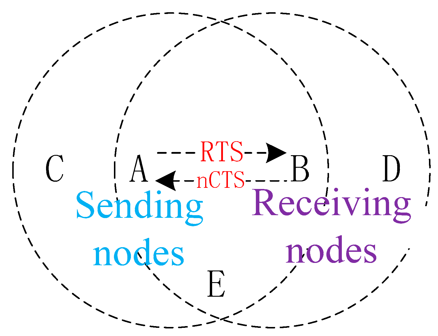
  • RTSC: The sending node A sends data to node B. If A is in congestion, RTSC will be sent; otherwise, RTS will be sent.
  • nCTS: After receiving the RTS frame, the receiving node B judges its own congestion status. If it is congested, it returns an nCTS frame and refuses to receive data; otherwise, it returns a CTS frame. If node A receives an nCTS, it cannot send packets to node B.
  • CTSC: The introduction of CTSC frames is mainly to solve the deadlock situation. A deadlock means that two congestion nodes, say A and B, need to send data to each other to relieve their own congestion, but they are in a state of mutually rejecting each other. If both node A and node B are in a congested status, node A and B send head-data in cache to each other. The sending node A will send the RTSC frame first, and node B will reply an nCTS to reject the data. Due to node B’s rejection, nodes A and B will be in a dead-end state until they exceed the upper limit of retransmission to drop the packet. Therefore, when node B receives the RTSC, if it is determined that a deadlock may occur, the CTSC frames are returned to each other to help relieve the congestion.
Using the above three new frames, when a node in the network is congested, it can rapidly transmit congestion information to the upstream nodes. Each upstream node performs hop-by-hop congestion control, and ultimately transmits congestion information to the source node, reducing the number of data transmissions from the source, resulting in better network performance.

3. Improvement Measures of the Algorithm

According to the introduction of the RTS/CTS handshake protocol in Section 2.1.1, the RTS and CTS frames reserve slot-time in the Network Allocation Vector (NAV) field (the specific value is the duration bit in the control frame) to indicate how long the node needs to back off after receiving the frame, so it can avoid collisions in sending data frames. The RTS/CTS protocol is proposed to solve the hidden terminal problem, but the exposed terminal problem also affects the network performance due to channel wastage caused by exposed terminals. An exposed terminal refers to a node that is within the coverage of the sending node and outside the coverage of the receiving node.
As shown in Figure 2, node C sends data to node F, but node A wants to send data to B too. Node A in this case is an exposed terminal. After receiving the RTS of node C, node A will perform a backoff. However, in reality, the respective receiving nodes are not within the receiving range of the sending node. Therefore, the two types of data do not collide at the receiving end so that node A can send data to node B. This exposed terminal problem causes a waste of channels.
Not only the exposed terminal problem, but for a congested network with heavy traffic loads, there will naturally be interactions of many nCTS frames. This will also cause great trouble. Suppose that node A needs to send data frames to node B, and node B replies an nCTS, then node A will not send data in the originally reserved time slot after receiving the frame. As shown in Figure 3, the surrounding neighboring nodes can be considered separately.
Node D is a hidden terminal, after receiving an nCTS, it will perform a backoff according to its duration. Node C, as an exposed terminal, will also perform a backoff after receiving an RTS. Node E can receive two control frames and will select the larger duration of the RTS and nCTS to back off. At this point, nodes A, C, D, and E will all be unable to send data, which will result in waste of channels and increase the network congestion.
In order to solve the above problems and optimize the performance of Semi-TCP, we have designed the following algorithm:
  • Set the duration of an nCTS to 0 to solve the backoff problem of the hidden terminal in Figure 2.
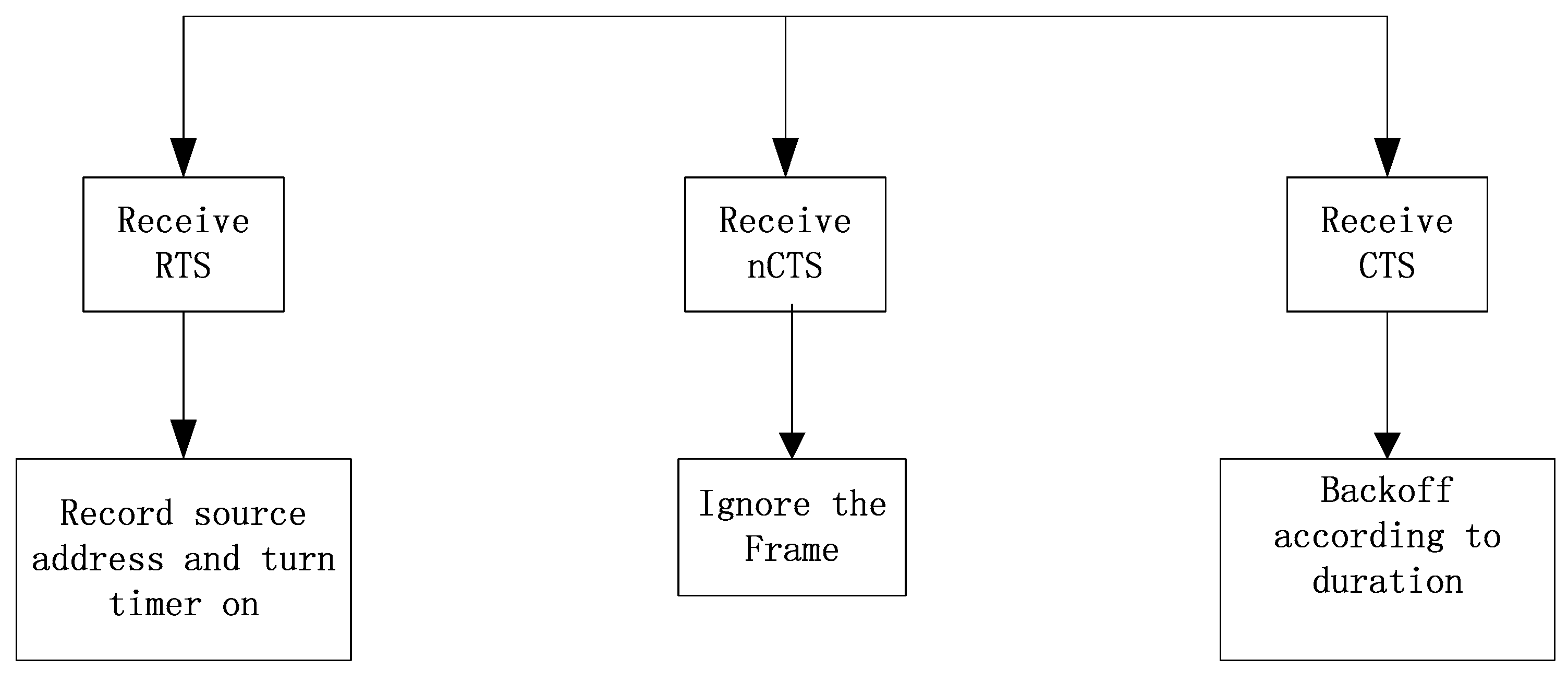
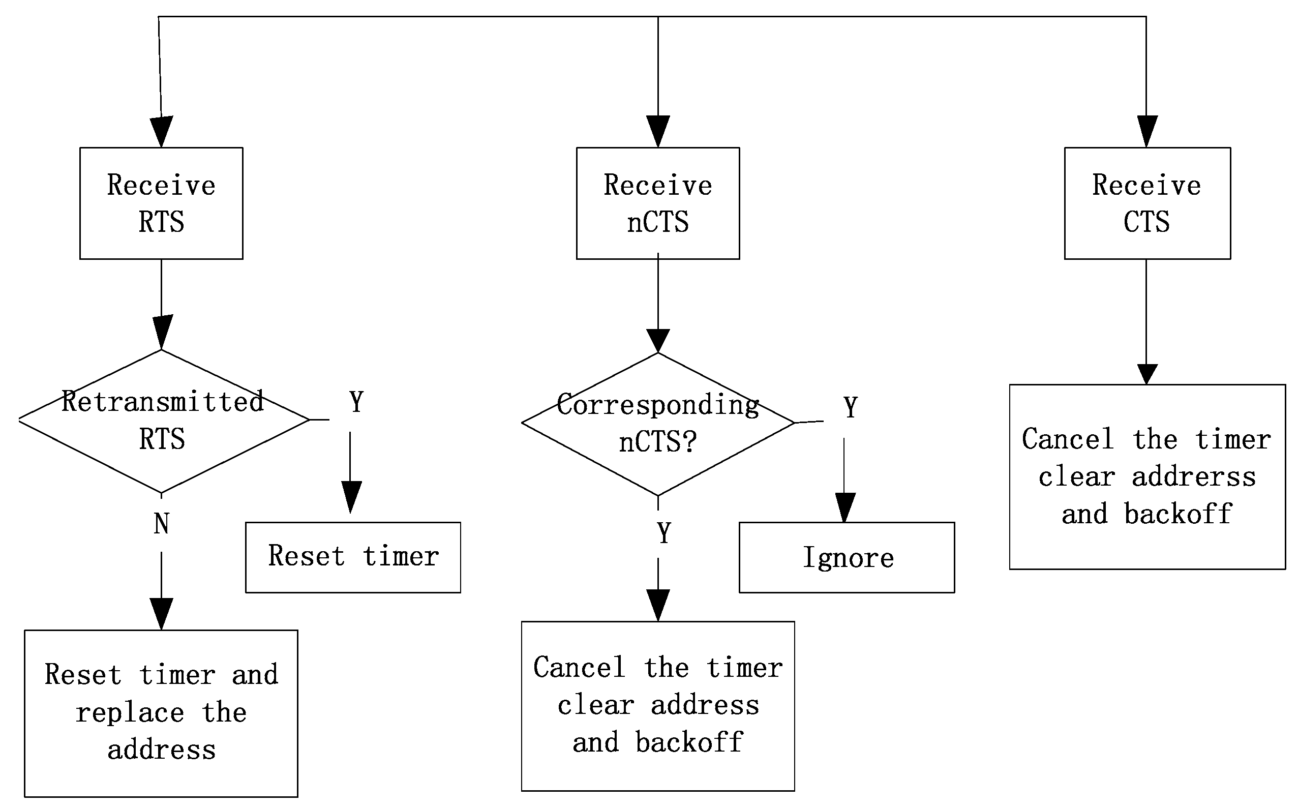
  • After the node receives an RTS frame that is not destined to itself, the node records the sending address of the frame, and at the same time initiates a Timer-for-Exposed-Terminal (TET). If no CTS or retransmitted RTS to this address is received within the certain time interval, it is determined that there is an exposed terminal and the backoff can be cancelled.
  • If an nCTS is received before the Timer-for-Exposed-Terminal (TET) times out, cancel the backoff.
  • When the node receives an RTS frame that is not sent to itself before the TET times out: (i) if it receives an RTS frame from another node that is not for itself, it records a new address and resets the timer; (ii) if receiving a CTS frame that is not addressed to itself, it unconditionally backs off according to Duration.
  • If the node receives any control frame sent to itself when the TET is on, it will be treated as a backoff state.
Regarding the duration of the TET, we have to consider the case of retransmission RTS and set the minimum value that meets the requirement. After analyzing the RTS/CTS protocol, the node will start a retransmission timer after sending the RTS frame. The value of this retransmission timer is shown in formula (1), where PropDelay is the propagation delay and SIFS is the short frame interval, transmitDelay (CTS) is the transmission delay of the CTS frame, and slotTime is the waiting time.
h o l d F o r C t s = P r o p D e l a y + S I F S + t r a n s m i t D e l a y ( C T S ) + P r o p D l a y + s l o t T i m e
After the interval, if no response is received from the other nodes within the specified time, the RTS frame will be retransmitted. Therefore, after a node receives an RTS frame that is not sent to itself, if it does not even receive a retransmission RTS, it determines that it is an exposed terminal. The TET timer duration is as in formula (2), and transmitDelay is the transmission delay of the RTS.
h o l d F o r B a c k u p = ( h o l d F o r C t s P r o p D e l a y ) + t r a n s m i t D e l a y ( R T S ) + P r o p D l a y
Figure 4 shows the processing flow of the algorithm in the state that the TET timer is off when the node receives null pointers not sent to itself.
Figure 5 shows the processing flow of the algorithm when the TET timer is on when the node receives null pointers not sent to itself.

4. Experimental Simulation and Analysis

Throughput and delay are important network performance indicators and are used as the main criteria in the performance testing of Semi-TCP. The average throughput of the network intuitively indicates the transmission performance of the network. Increasing the throughput is the most important for the network optimization. Packet delay refers to the time interval from when the packet is sent by the sending node to when the destination node receives the packet. It includes queue delay, transmission delay, and propagation delay. In the statistics of the EXata simulation, the above parameters will be directly given to facilitate observation and comparison. EXata is a network emulator that lets one evaluate on-the-move communication networks faster and with more realism than any other tool. It uses a software virtual network (SVN) to digitally represent the entire network, the various protocol layers, antennas, and devices. The system can interoperate at one or more protocol layers, with real radios and devices to provide hardware-in-the-loop capabilities [20].

4.1. Simulation Scene and Parameters

This section simulates a ship ad-hoc network, which is a main component of the marine Internet. To reflect the characteristics of the marine Internet, it is necessary to establish a long-distance dynamic simulation scenario, which can be achieved by using the industrial version WiFi. Some nodes at sea move at certain speeds and cooperate with appropriate channel attenuation models. To test the congestion control algorithm, we established a congestion scenario. Therefore, multiple application data flows were added to reflect the differences in network throughput, packet loss rate, and average packet delay. The abstract scene of the simulation is shown in Figure 6.
The transmission range of each node in the scenario only covers the nodes adjacent to it. The data flow from node A to node C and node F needs to be forwarded by the intermediate node. The data flow from node J to node K is mainly to verify the performance of the improved Semi-TCP algorithm when node A is an exposed terminal, and the two data flows from node B are mainly used to create network congestion.
The basic parameters of the scene are set as Table 1 [21,22]:
For the ease of description, the semi-TCP congestion control protocols based on RTS/CTS will be abbreviated as Semi-TCP-RTS, and the improved one as Semi-TCP-RTS-V2. We compared the three algorithms: Semi-TCP-RTS, Semi-TCP-RTS-V2, and TCP-Lite—a lightweight version of TCP.

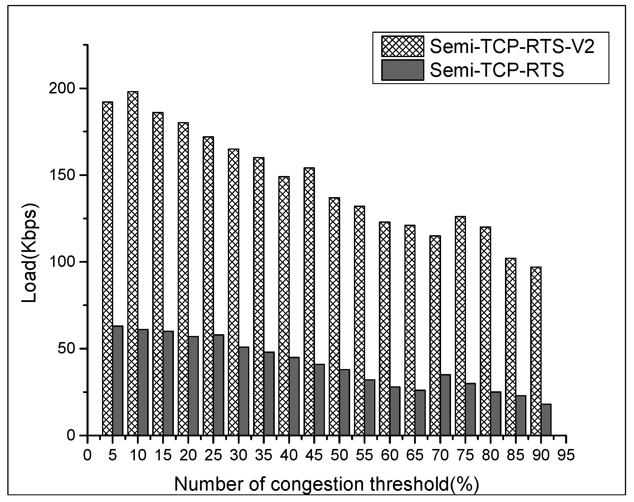
4.2. Simulation Results Analysis

In order to analyze the effect of the threshold value on the performance of the protocols, we varied the threshold settings in the simulation. As a lot of data is flowing at the same time, we summed up the average throughput of each data stream and compared them, with the results shown in Figure 7.
From Figure 7, it can be seen that the two Semi-TCP protocols have a significant improvement in the throughput of the network compared to TCP-Lite. This is because TCP-Lite misjudges the network congestion status inferred from packet loss for the bad channel quality and mistakenly reduces the sending window, which limits the network performance. The nodes judge themselves to determine whether they are congested or not depending on the congestion threshold. From this figure, we can also see that the change of the threshold value does not have a great impact on the overall throughput of the network. However, as the threshold value increases, the average length of the queue will inevitably increase, and the average queue delay increases as well. The following data statistics are collected from the average queue delay of node J in the J → K data stream. At the same time, the total throughput of Semi-TCP-RTS-V2 is slightly lower than Semi-TCP-RTS, and the results are explained jointly by using Figure 8 below.
From Figure 8, it is found that the load of node A is much smaller than the sum of the average throughput of the entire network. In fact, there is even a failure of a data stream connection in node A in the Semi-TCP-RTS test. This is because node A is affected by node J and node B while sending data; it is not only acting as an exposed terminal for J → K and B → C data streams, but also is in the B → D data stream while node D is in its receiving range, which affects the data-sending of node A. Apart from that, the congestion caused by the two data streams of node B restrict node A from sending data, resulting in the above phenomena.
In addition, it can be clearly observed that in the improved protocol, node A will increase its load when the entire network throughput decreases. This shows that the gap between node A and the other 2 sending nodes has shrunk, meaning that the fairness of the data stream has improved. Because the exposed terminal problem with the Semi-TCP-RTS-V2 has been relieved at a certain level, the load has also been increased. The overall throughput shown in Figure 7 is lower than Semi-TCP-RTS, because it takes time to define the exposed terminal with the improved protocol. At the same time, the other two sending nodes enter into the process of the exposed terminal’s judgment when node A is sending packets, yielding the above result.
As shown in Figure 9, as the threshold is consistent, there is no difference between Semi-TCP-RTS and Semi-TCP-RTS-V2, which is also in line with the expectations.

5. Conclusions

In the marine Internet, both the wireless ad hoc networks and the opportunistic networks can use the IEEE 802.11 protocol standard. This paper elaborates on the proposed Semi-TCP-RTS congestion control algorithm and proposes an improved Semi-TCP-RTS called Semi-TCP-RTS-v2. It solves the exposed terminal problem and the waste of channel resources due to the interaction of nCTS frames. Finally, three protocols were implemented and tested on the Exata simulation platform, and a comparative analysis was performed. The results show that Semi-TCP-RTS-V2 algorithm has better performance than TCP-Lite and Semi-TCP-RTS with improved fairness.

Author Contributions

L.Z., S.J. and C.X. designed the marine Internet architecture and the algorithm; L.Z. and C.X. wrote the paper, and S.J. reviewed the manuscript with many suggestions and revisions.

Acknowledgments

Support from the National Natural Science Foundation of China (NSFC) (Grants 61472237 and U1701265) is gratefully acknowledged.

Conflicts of Interest

The authors declare no conflict of interest.

References

  1. Jiang, S. On the marine internet and its potential applications for underwater inter-networking. In Proceedings of the 8th ACM International Conference on Underwater Networks and Systems, Kaohsiung, Taiwan, 11–13 November 2013. [Google Scholar]
  2. Jiang, S.M. A Possible Development of Marine Internet: A Large Scale Heterogeneous Wireless Network. In Proceedings of the International Conference Next Generation Wired/Wireless Networking NEW2AN, Saint-Petersburg, Russia, 26–28 August 2015. [Google Scholar]
  3. Jiang, S.M. Fostering Marine Internet with Advanced Maritime Radio System Using Spectrums of Cellular Networks. In Proceedings of the IEEE International Conference on Communication Systems (ICCS), Shenzhen, China, 14–16 December 2016. [Google Scholar]
  4. Afanasyev, A.; Tilley, N.; Reiher, P.; Kleinrock, L. Host-to-host Congestion Control for TCP. IEEE Commun. Surv. Tutor. 2010, 12, 304–342. [Google Scholar] [CrossRef]
  5. Hanbali, A.A.; Altman, E.; Nain, P. A Survey of TCP over Ad Hoc Networks. IEEE Commun. Surv. Tutor. 2005, 7, 23–36. [Google Scholar] [CrossRef]
  6. Sardar, B.; Saha, D. Survey of TCP Enhancements for Last-hop Wireless Networks. IEEE Commun. Surv. Tutor. 2006, 8, 20–34. [Google Scholar] [CrossRef]
  7. Sundaresan, K.; Anantharaman, V.; Hsieh, H.Y.; Sivakumar, R. ATP: A reliable transport protocol for ad hoc networks. IEEE Trans. Mob. Comput. 2003, 4, 64–75. [Google Scholar]
  8. Christian, L.; Bjorn, S.; Martin, M. A Survey on Congestion Control or Mobile Ad Hoc Networks. Wiley Wirel. Commun. Mob. Comput. 2007, 7, 655–676. [Google Scholar]
  9. Fu, Z.; Greenstein, B.; Meng, X. Design and Implementation of a TCP-friendly Transport Protocol for Ad Hoc Wireless Networks. In Proceedings of the 10th IEEE International Conference on Network Protocols, Paris, France, 12–15 November 2002. [Google Scholar]
  10. Monzer, H.A.M.; Suhaidi, H. Loss Detection and Recovery Techniques for TCP in Mobile Ad Hoc Network. In Proceedings of the International Conference on Network Applications, Protocols and Services, Kedah, Malaysia, 22–23 September 2010; IEEE Press: Washington, DC, USA, 2010. [Google Scholar]
  11. Cai, Y. Semi-TCP Congestion Control Algorithm Based on RTS/CTS in Multi Hop Wireless Network; South China University of Technology: Guangzhou, China, 2010. [Google Scholar]
  12. Jiang, S.M.; Zuo, Q.; Wei, G. Decoupling congestion control from TCP for multi-hop wireless networks: Semi-TCP. In Proceedings of the ACM MobiCom Workshop on Challenged Networks (CHANTS), Beijing, China, 20–25 September 2009. [Google Scholar]
  13. Liu, M.; Jiang, S.; Lu, Y. Realization of. Semi-TCP protocol in wireless multi hop networks. Comput. Eng. 2012, 5, 79–82. [Google Scholar]
  14. Zhang, W. Violation analysis of wireless mobile Ad Hoc network. China Sci. Technol. 2012, 13, 62–64. [Google Scholar] [CrossRef]
  15. Liu, Z.; Xu, F. Research on hidden and exposed terminal problems in mobile. Ad Hoc Netw. 2010, 6, 30–37. [Google Scholar]
  16. Liu, S.S. ATCPL TCP for mobile ad hoc networks. IEEE J. Sel. Areas Commun. 2001, 19, 1300–1315. [Google Scholar] [CrossRef]
  17. Aloizio, P.; Silva, S.B.; Celso, M.; Hirata, K.O. A survey on congestion control for delay and disruption tolerant networks. Ad Hoc Netw. 2015, 25 Pt B, 480–494. [Google Scholar]
  18. Tassiulas, L. Adaptive back-pressure congestion control based on local Information. IEEE Trans. Autom. Control 1995, 40, 236–250. [Google Scholar] [CrossRef]
  19. Silva, A.P.; Obraczka, K.; Burleigh, S.; Hirata, C.M. Smart Congestion Control for Delay- and Disruption Tolerant Networks. In Proceedings of the 13th Annual IEEE International Conference on Sensing, Communication, and Networking (SECON), London, UK, 27–30 June 2016; pp. 1–9. [Google Scholar]
  20. Exata Network Emulator Software. Available online: https://web.scalable-networks.com/exata-network-emulator-software (accessed on 1 May 2017).
  21. Wu, S.; Zeng, Q.; Zhao, J. Long-distance Wireless Data Acquisition System Based on Wi-Fi. Nucl. Electron. Detect. Technol. 2012, 32, 960–964. [Google Scholar]
  22. Wang, Z.; Fan, W.; Zheng, L. Study and Simulation of Wave Propagation Loss Model of Sea Surface. J. Radio Wave Sci. 2008, 236, 1095–1099. [Google Scholar]
Figure 1. The example of hidden terminals.
Futureinternet 10 00044 g001
Figure 2. An example of exposed terminals.
Futureinternet 10 00044 g002
Figure 3. Interaction of nCTS.
Futureinternet 10 00044 g003
Figure 4. The processing flow of a node receiving a control frame that does not belong to itself when TET is off.
Futureinternet 10 00044 g004
Figure 5. The processing flow of receiving a control frame that does not belong to itself when TET is on.
Futureinternet 10 00044 g005
Figure 6. Abstract simulation scenario of the ship ad hoc network.
Futureinternet 10 00044 g006
Figure 7. Throughput with various CTh settings in a congestion network.
Futureinternet 10 00044 g007
Figure 8. Load with various CTh settings of node A.
Futureinternet 10 00044 g008
Figure 9. Average queue delay with various CTh settings of node J.
Futureinternet 10 00044 g009
Table 1. Basic parameters of the scenario.
Simulation ParametersValues
Nodes’ moving speed7~10 m/s
Channel modelTwoRayGround
Attenuation modelRicean, K = 5
Frequency channel2.4 G
MAC rate11 Mbps
Sending queueFIFO, Length 150 Kb
Transmission power33 dBm
Routing protocolAODV

