
Energy Efficient Power Allocation for the Uplink of Distributed Massive MIMO Systems

Abstract
:1. Introduction
1.1. Related Work
1.2. Motivation and Contribution
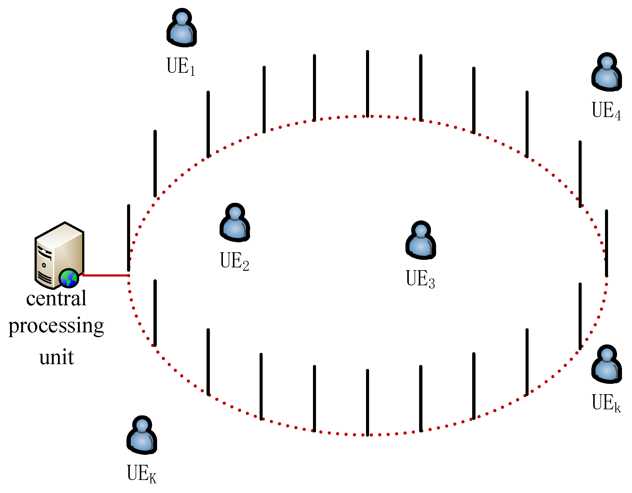
- A tight EE expression is derived in closed-form for the distributed massive MIMO system with circular antenna array.
- To maximize the EE, an optimization problem was formulated to jointly determine the transmit power, power allocation, and the number of antennas. Further, the NP-hard problem is solved by one-dimension search.
- For a given number of antennas and the total transmit power, the optimal power allocation coefficients are derived in closed-form expressions.
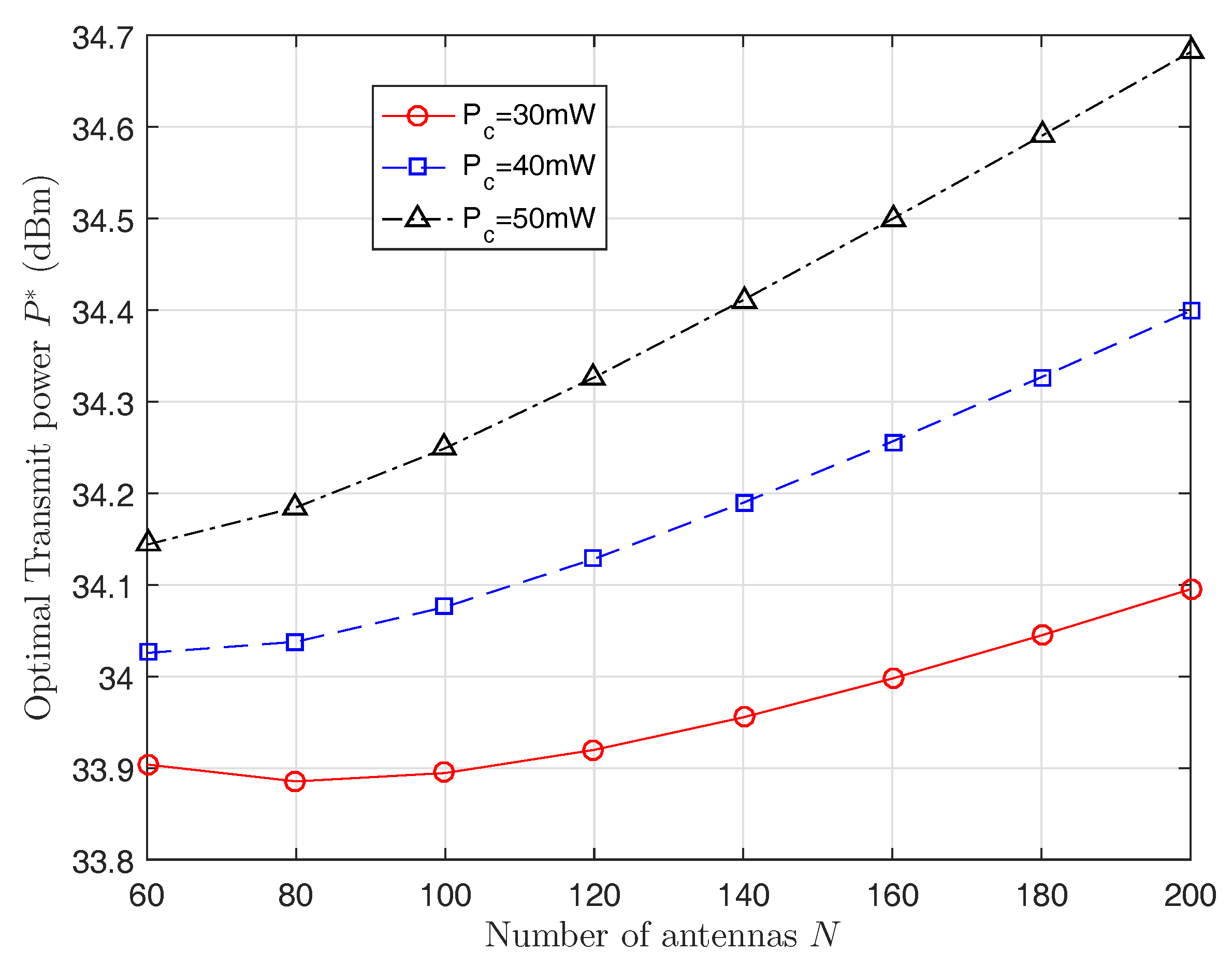
- For a given number of antennas, the optimal total transmit power is derived in closed-form.
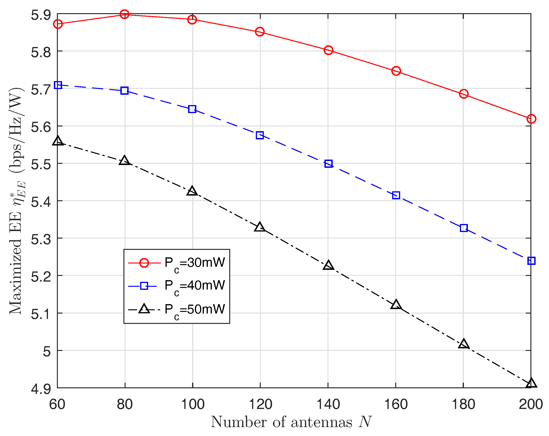
- To further maximize the EE, the number of transmit antennas are optimized by one-dimension search.
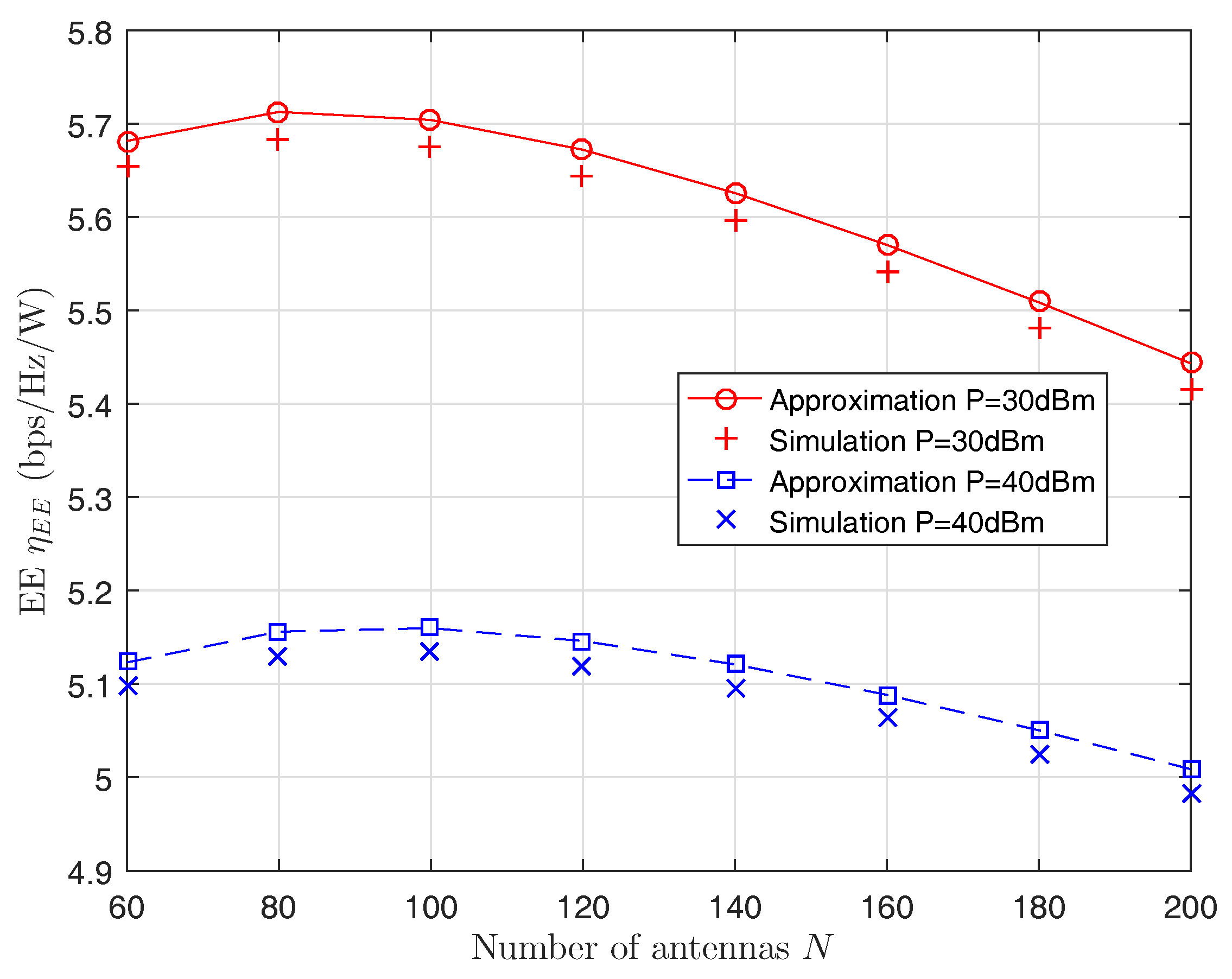
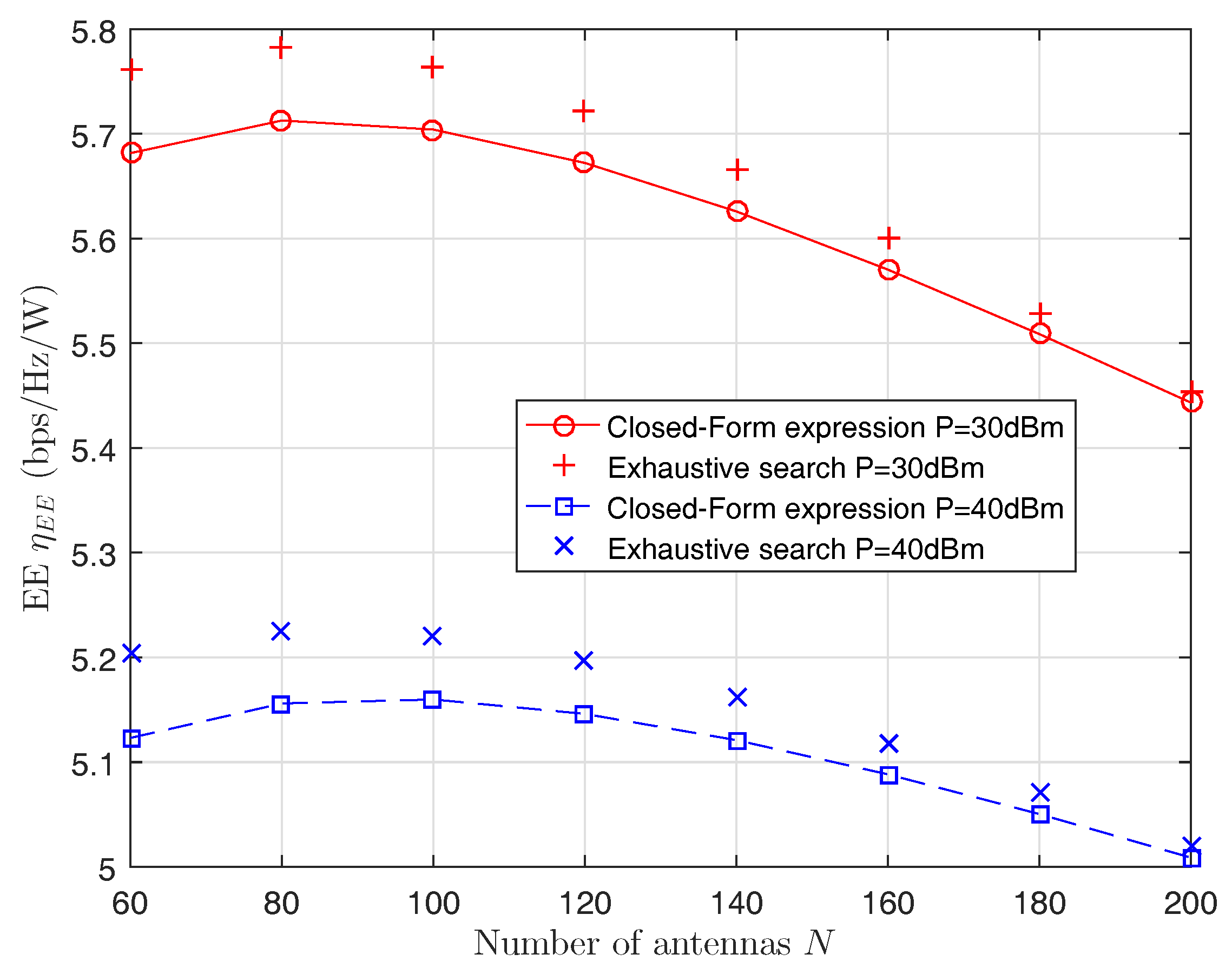
- Simulation results validate the accuracy and the low-complexity of our proposed scheme.
2. System Model
3. Energy Efficiency Analysis
4. Energy Efficiency Optimization
4.1. Problem Formulation
4.2. Optimal Power Allocation for Given P and N
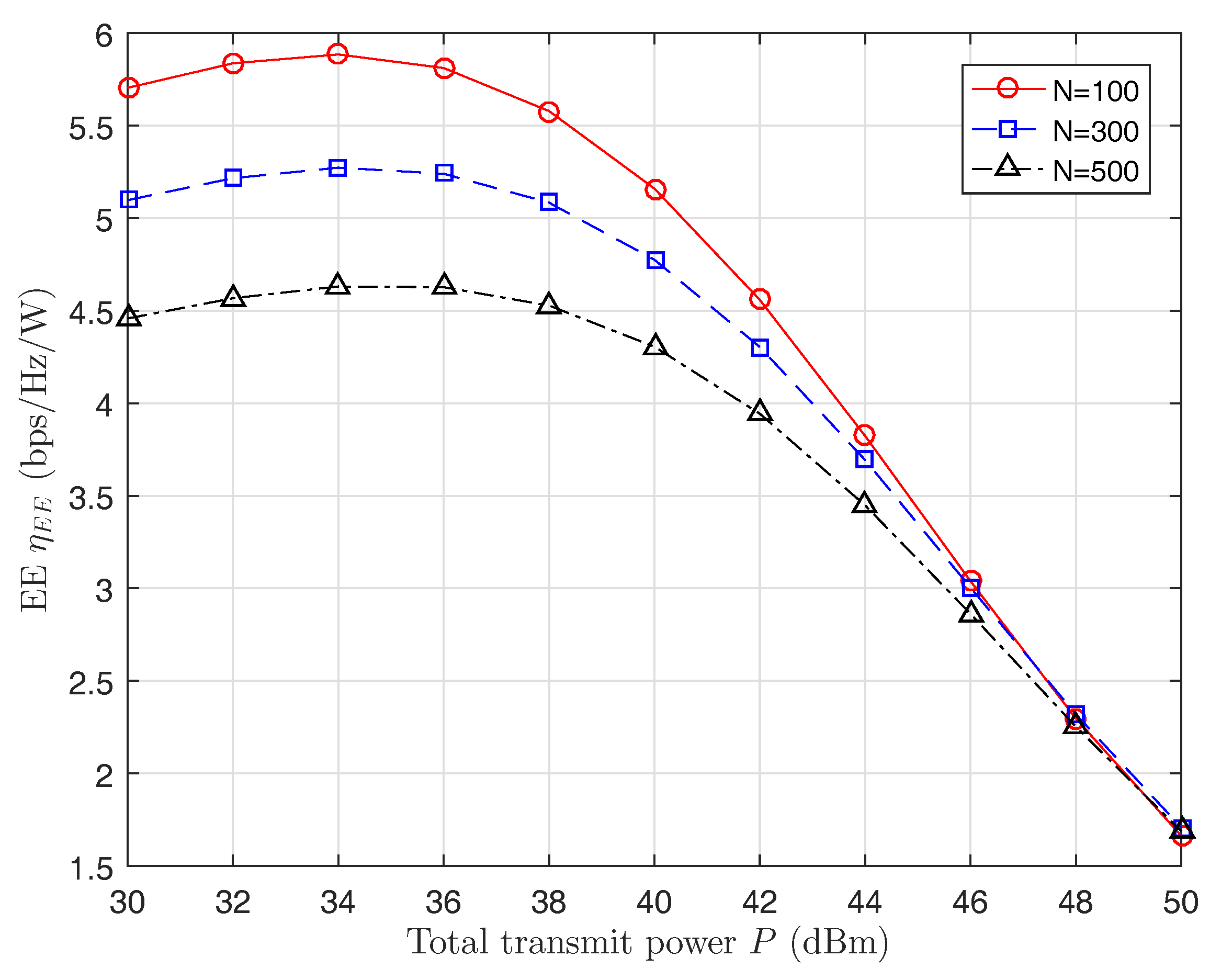
4.3. Optimal P for Given N
4.4. Optimal N
5. Numerical and Simulation Results
6. Conclusions
Acknowledgments
Author Contributions
Conflicts of Interest
References
- Gupta, A.; Jha, R.K. A survey of 5G network: Architecture and emerging technologies. IEEE Access 2015, 3, 1206–1232. [Google Scholar] [CrossRef]
- Wong, V.; Schober, R.; Ng, D.W.K.; Wang, L. Key Technologies for 5G Wireless Systems; Cambridge University Press: Oxford, UK, 2017. [Google Scholar]
- Larsson, E.G.; Edfors, O.; Tufvesson, F.; Marzetta, T.L. Massive MIMO for next generation wireless systems. IEEE Commun. Mag. 2006, 52, 186–195. [Google Scholar] [CrossRef]
- Zheng, K.; Zhao, L.; Mei, J.; Shao, B.; Xiang, W.; Hanzo, L. Survey of large-scale MIMO systems. IEEE Commun. Surv. Tutor. 2015, 17, 1738–1760. [Google Scholar] [CrossRef]
- Ngo, H.Q.; Larsson, E.G.; Marzetta, T.L. The multicell multiuser MIMO uplink with very large antenna arrays and a finite-dimensional channel. IEEE Trans. Commun. 2013, 61, 2350–2361. [Google Scholar] [CrossRef]
- Ngo, H.Q.; Matthaiou, M.; Duong, T.Q.; Marzetta, T.L. Uplink performance analysis of multicell MU-SIMO systems with ZF receivers. IEEE Trans. Veh. Technol. 2012, 62, 4471–4483. [Google Scholar]
- Zhao, L.; Zheng, K.; Long, H.; Zhao, H. Performance analysis for downlink massive MIMO system with ZF precoding. Trans. Emerg. Telecommun. Technol. 2014, 25, 1219–1230. [Google Scholar] [CrossRef]
- Lin, Y.; Li, X.; Fu, W.; Hei, Y. Spectral efficiency analysis for downlink massive MIMO systems with MRT precoding. China Commun. 2015, 12, 67–73. [Google Scholar] [CrossRef]
- Ngo, H.Q.; Larsson, E.G.; Marzetta, T.L. Energy and spectral efficiency of very large multiuser MIMO systems. IEEE Trans. Commun. 2013, 61, 1436–1449. [Google Scholar]
- Ha, D.; Lee, K.; Kang, J. Energy efficiency analysis with circuit power consumption in massive MIMO systems. In Proceedings of the 2013 IEEE 24th International Symposium on Personal, Indoor and Mobile Radio Communications (PIMRC Workshops), London, UK, 8–9 September 2013; pp. 938–942. [Google Scholar]
- Bjornson, E.; Sanguinetti, L.; Hoydis, J.; Debbah, M. Optimal design of energy-efficient multi-user MIMO systems: Is massive MIMO the answer? IEEE Trans. Wirel. Commun. 2015, 14, 3059–3075. [Google Scholar] [CrossRef]
- Zhao, L.; Zhao, H.; Zheng, K.; Zhang, J. Energy efficient power allocation algorithm for downlink massive MIMO with MRT precoding. In Proceedings of the 2013 IEEE 78th Vehicular Technology Conference (VTC2013-Fall), Las Vegas, NV, USA, 2–5 September 2013; pp. 1–5. [Google Scholar]
- Ng, D.W.K.; Lo, E.S.; Schober, R. Energy-efficient resource allocation in OFDMA systems with large numbers of base station antennas. IEEE Trans. Veh. Technol. 2012, 11, 3292–3304. [Google Scholar]
- Zhu, H.; Wang, J. Chunk-based resource allocation in OFDMA systems—Part I: Chunk allocation. IEEE Trans. Commun. 2009, 57, 2734–2744. [Google Scholar]
- Zhu, H.; Wang, J. Chunk-based resource allocation in OFDMA systems—Part II: Joint chunk, power and bit allocation. IEEE Trans. Commun. 2012, 60, 499–509. [Google Scholar] [CrossRef]
- Ng, D.W.K.; Lo, E.S.; Schober, R. Energy-efficient resource allocation in multi-cell OFDMA systems with limited backhaul capacity. IEEE Trans. Wirel. Commun. 2012, 11, 3618–3631. [Google Scholar] [CrossRef]
- Liu, D.; Wang, L.; Chen, Y.; Zhang, T. Distributed energy efficient fair user association in massive MIMO enabled HetNets. IEEE Commun. Lett. 2015, 19, 1770–1773. [Google Scholar] [CrossRef]
- Bjornson, E.; Hoydis, J.; Kountouris, M.; Debbah, M. Massive MIMO systems with non-ideal hardware: Energy efficiency, estimation, and capacity limits. IEEE Trans. Inf. Theory 2014, 60, 7112–7139. [Google Scholar] [CrossRef]
- Guo, K.; Guo, Y.; Ascheid, G. Security-Constrained power allocation in MU-Massive-MIMO with distributed antennas. IEEE Trans. Wirel. Commun. 2016, 15, 8139–8153. [Google Scholar] [CrossRef]
- Zhu, H. Performance comparison between distributed antenna and microcellular systems. IEEE J. Sel. Areas Commun. 2011, 29, 1151–1163. [Google Scholar] [CrossRef]
- Senanayake, R.; Smith, P.; Yeoh, P.L.; Evans, J. An SNR approximation for distributed massive MIMO with zero forcing. IEEE Commun. Lett. 2016, 19, 1885–1888. [Google Scholar] [CrossRef]
- Kamga, G.N.; Xia, M.; Aissa, S. Spectral-Efficiency analysis of massive MIMO systems in centralized and distributed schemes. IEEE Trans. Commun. 2016, 64, 1930–1941. [Google Scholar] [CrossRef]
- Gao, X.; Zhang, J.; Wang, Z.; Jin, J. Optimal precoder design maximizing the worst-case average received SNR for massive distributed MIMO systems. IEEE Commun. Lett. 2015, 19, 589–592. [Google Scholar] [CrossRef]
- He, C.; Yin, J.; He, Y.; Huang, M.; Zhao, B. Energy efficiency of distributed massive MIMO systems. J. Commun. Netw. 2016, 18, 649–657. [Google Scholar]
- Kim, W.; Yoon, W. Energy efficiency maximisation for WPCN with distributed massive MIMO system. Electron. Lett. 2016, 19, 1642–1644. [Google Scholar] [CrossRef]
- Yang, A.; Jing, Y.; Xing, C.; Fei, Z. Performance analysis and location optimization for massive MIMO systems with circularly distributed antennas. IEEE Trans. Wirel. Commun. 2015, 14, 5659–5671. [Google Scholar] [CrossRef]


© 2017 by the authors. Licensee MDPI, Basel, Switzerland. This article is an open access article distributed under the terms and conditions of the Creative Commons Attribution (CC BY) license (http://creativecommons.org/licenses/by/4.0/).
Share and Cite
Wang, X.; Yang, Y.; Sheng, J. Energy Efficient Power Allocation for the Uplink of Distributed Massive MIMO Systems. Future Internet 2017, 9, 21. https://doi.org/10.3390/fi9020021
Wang X, Yang Y, Sheng J. Energy Efficient Power Allocation for the Uplink of Distributed Massive MIMO Systems. Future Internet. 2017; 9(2):21. https://doi.org/10.3390/fi9020021
Chicago/Turabian StyleWang, Xinhua, Yan Yang, and Jinlu Sheng. 2017. "Energy Efficient Power Allocation for the Uplink of Distributed Massive MIMO Systems" Future Internet 9, no. 2: 21. https://doi.org/10.3390/fi9020021
APA StyleWang, X., Yang, Y., & Sheng, J. (2017). Energy Efficient Power Allocation for the Uplink of Distributed Massive MIMO Systems. Future Internet, 9(2), 21. https://doi.org/10.3390/fi9020021