Article

Use Cases with Economics and Simulation for Thermo-Chemical District Networks

1
Architectural Engineering, KU Leuven, Kasteelpark Arenberg 1—box 2431, 3001 Leuven, Belgium
2
Watergy GmbH, Oderberger Strasse 3, 10437 Berlin, Germany
3
Sir Joseph Swan Centre, University of Newcastle, Newcastle upon Tyne NE1 7RU, UK
4
TU Berlin, Strasse des 17. Juni 152, 10623 Berlin, Germany
*
Author to whom correspondence should be addressed.
Sustainability 2018, 10(3), 599; https://doi.org/10.3390/su10030599
Submission received: 30 November 2017 / Revised: 12 February 2018 / Accepted: 13 February 2018 / Published: 26 February 2018
(This article belongs to the Special Issue Sustainable Utilization of Waste Heat)

Abstract

:
Thermo-chemical networks using absorption and desorption to capture and valorise the potential of very low-grade residual heat (20 °C to 60 °C) to offer a reduction of end user costs and increased primary energy efficiency. The paper demonstrates the technical and economic potential of thermo-chemical networks by defining use cases and their related level of energy efficiency and technological feasibility. Furthermore, specific economic scenarios, including estimations on investment and operation costs, demonstrate the economic benefit of the technology. Simple payback periods between about 0.5 and 7.5 years indicate a good economic feasibility with end user costs below 4 €ct/kWh-equivalent and refunds of 0.5 to 1 €ct/kWh for the required residual heat. Due to the low-temperature characteristics of the relevant systems and services, detailed simulations are required to approve the functioning and viability of the new technology. For this purpose, the paper demonstrates the simulation outline using the example of space heating based on a low-temperature air heating system partially driven with thermo-chemical fuel.

1. Introduction

Low-grade excess heat from industry and from renewables (e.g., from solar thermal collectors) remains largely unused today. However, a large part of the excess heat is emitted at low temperature levels. Transport and storage of such heat potentials with conventional thermal district networks is difficult due to the thermal losses that occur in these networks. Solutions discussed today include the management of different temperature levels in the network, as well as solutions based on heat pump technology operating at the end-user side. However, high shares of electric power for heat supply and increased investment costs in the network are limiting the benefits in means of profitability and sustainability. Therefore, this paper proposes the development of thermo-chemical networks that are able to store thermal energy in the form of an absorption potential, i.e., a forced condensation of humidity. Thermo-chemical materials allow to convert latent heat in the form of humidity in the absorption process and releases a high amount of thermal energy during the phase change from water vapour to water. This energy can be used for space heating; desiccated air can serve in drying processes and, furthermore, dry air allows for humidity control in buildings, a function which is required more and more within highly-sealed modern or refurbished buildings. In combination with water evaporation, the material can also be used for space cooling. The first advantage of thermo-chemical potential is that no thermal losses occur during transport as the absorption process only takes place if humidity is present. The second advantage is that there is no need for a sequence of temperature levels in the network. The provided service can operate at a temperature level, higher than the available excess heat.
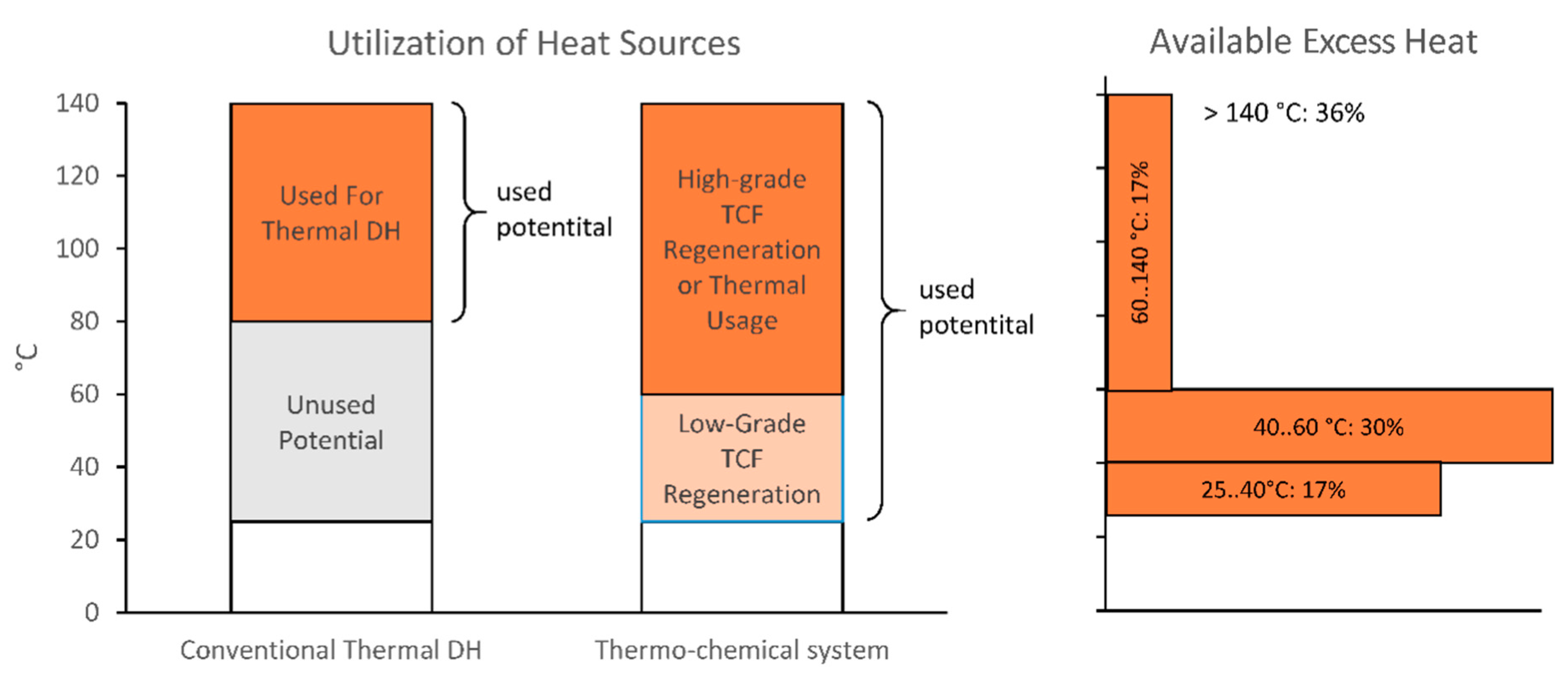
A large amount of excess heat is available at very low temperature levels. For instance, a study from Norway [1] shows that nearly 50% of available heat is provided below 60 °C (Figure 1). This temperature level cannot be exploited well by conventional district heating technology and often remains unused. The regeneration of thermo-chemical fluids (TCF) can take place at such low temperatures, as for ambient air, a low shift in temperature decreases the relative humidity sufficiently. Therefore, the thermo-chemical process has the potential to increase the utilization of low-grade excess heat. However, for a feasible network to identifying the demand-side application cases to be supplied with the regenerated fluid is required.
The aim of the paper is to examine the feasibility of a thermo-chemical network. For this examination, an examination of the application of service in the form of use cases with their technological requirements and schemes is required, as well as the economic benefits. Furthermore, processes, such as the application of absorption for heating, are quite complex, which requires the application of dynamic simulation to understand if they are working. An examination of the technological feasibility, the economic benefits and dynamic behaviour at the same time is required to gain a comprehensive understanding of such a network and its specific potentials.
The basis for this analysis is an examination of thermo-chemical processes within specific use cases and related services in Section 3. This section is mainly based on methods of Requirements Engineering with use cases and technical schemes. Section 4 develops economic scenarios to shed light on the means of actual implementation. The method used in this section is simple playback. Section 5 examines, in detail, how space heating and humidity control works by means of a dynamic heat and humidity simulation model. Each section forms a different view on the use cases of a thermo-chemical network. The methods are described in detail at the beginning of each section.

2. Principles and Technology

2.1. Basic Principles of Thermo-Chemical Networks

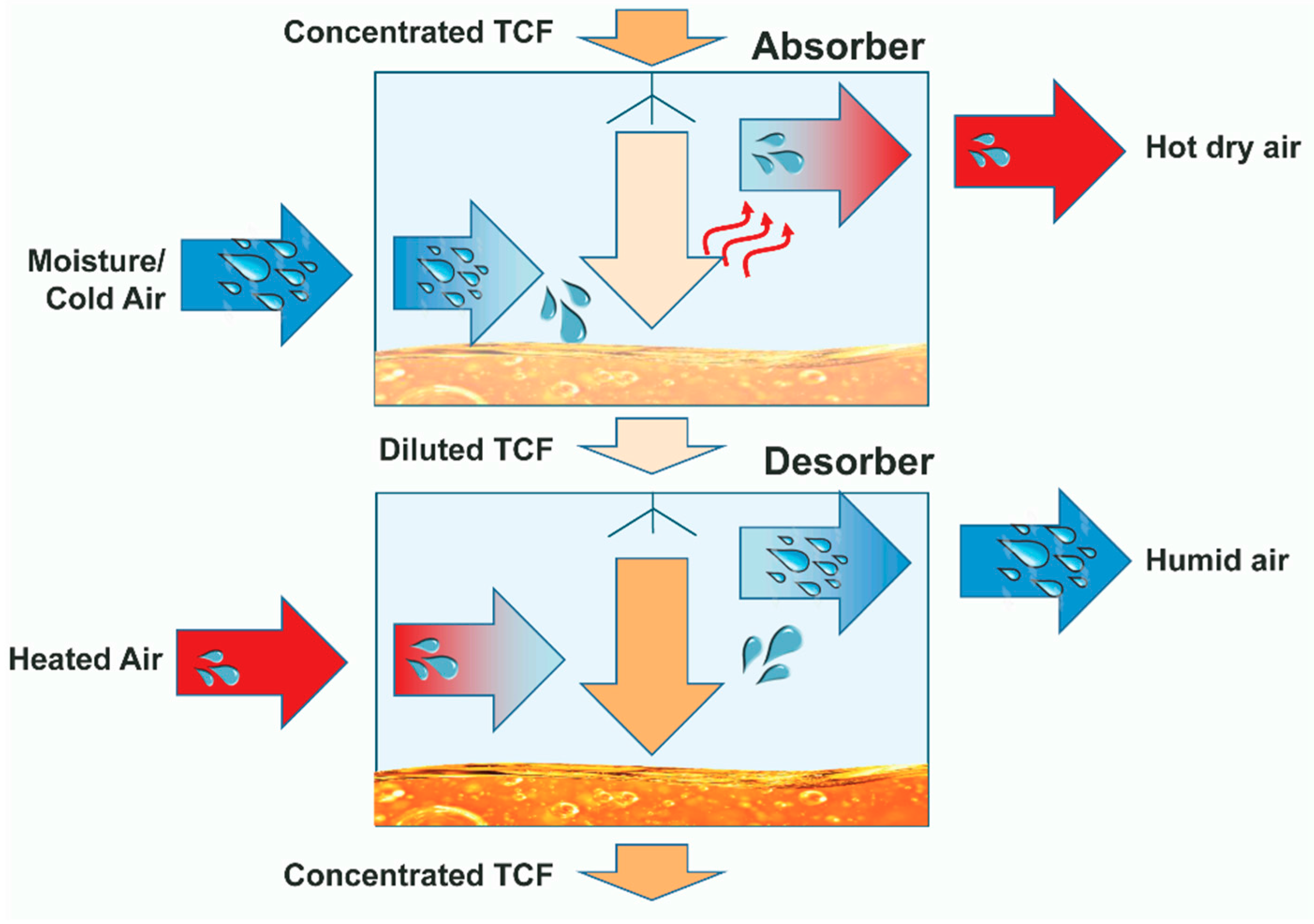
The thermo-chemical technology is based on two fundamental processes: (1) absorption and (2) desorption (Figure 2). Absorption is the process in that forced condensation in the TCF takes place. This process releases around 680 kWh/t of water. Depending on the concentration of the TCF, it takes place at the resulting equilibrium humidity. Desorption is the reversion of this process which, again, requires 680 kWh/t thermal energy input.
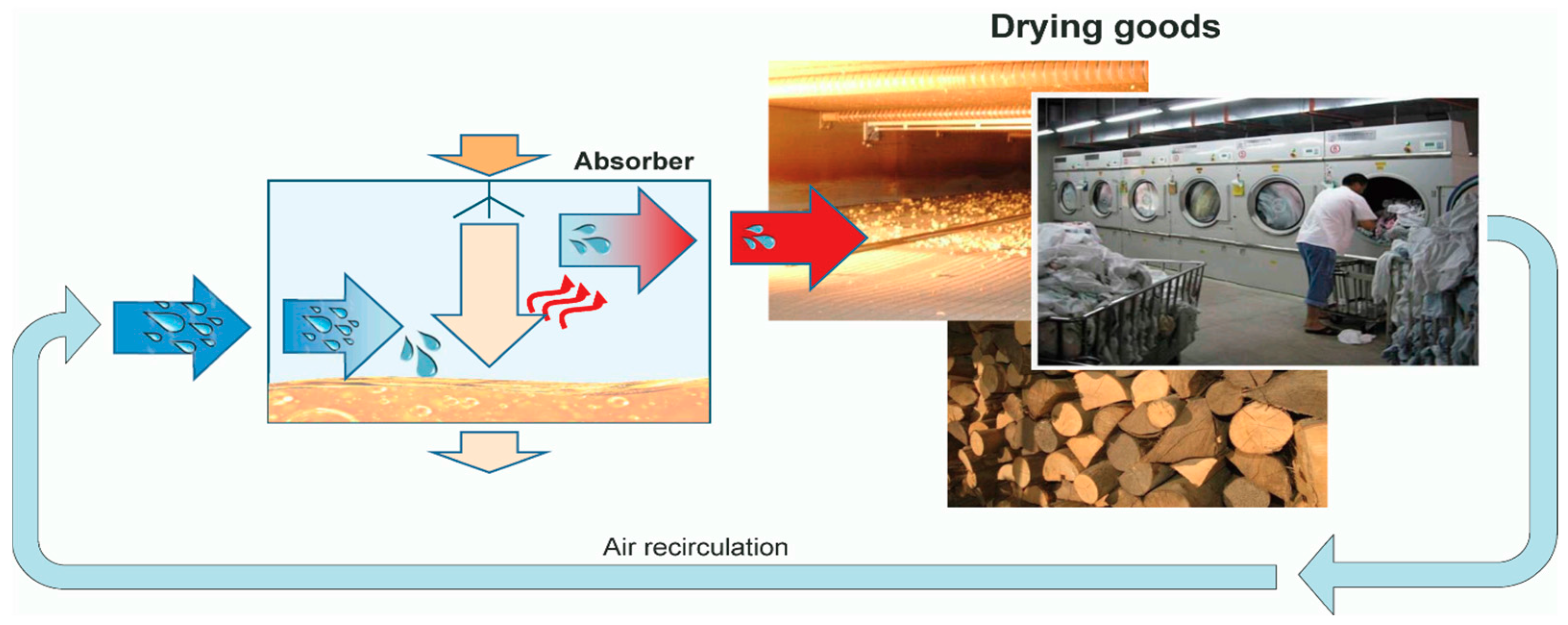
These two processes form the basis for heating, cooling and drying. The basic schemes are shown in Figure 3, Figure 4 and Figure 5. Drying directly exploits the dry warm air that is the result of the drying process. By applying air recirculation, the heat and humidity losses are drastically reduced which leads to a highly-improved energy efficiency.
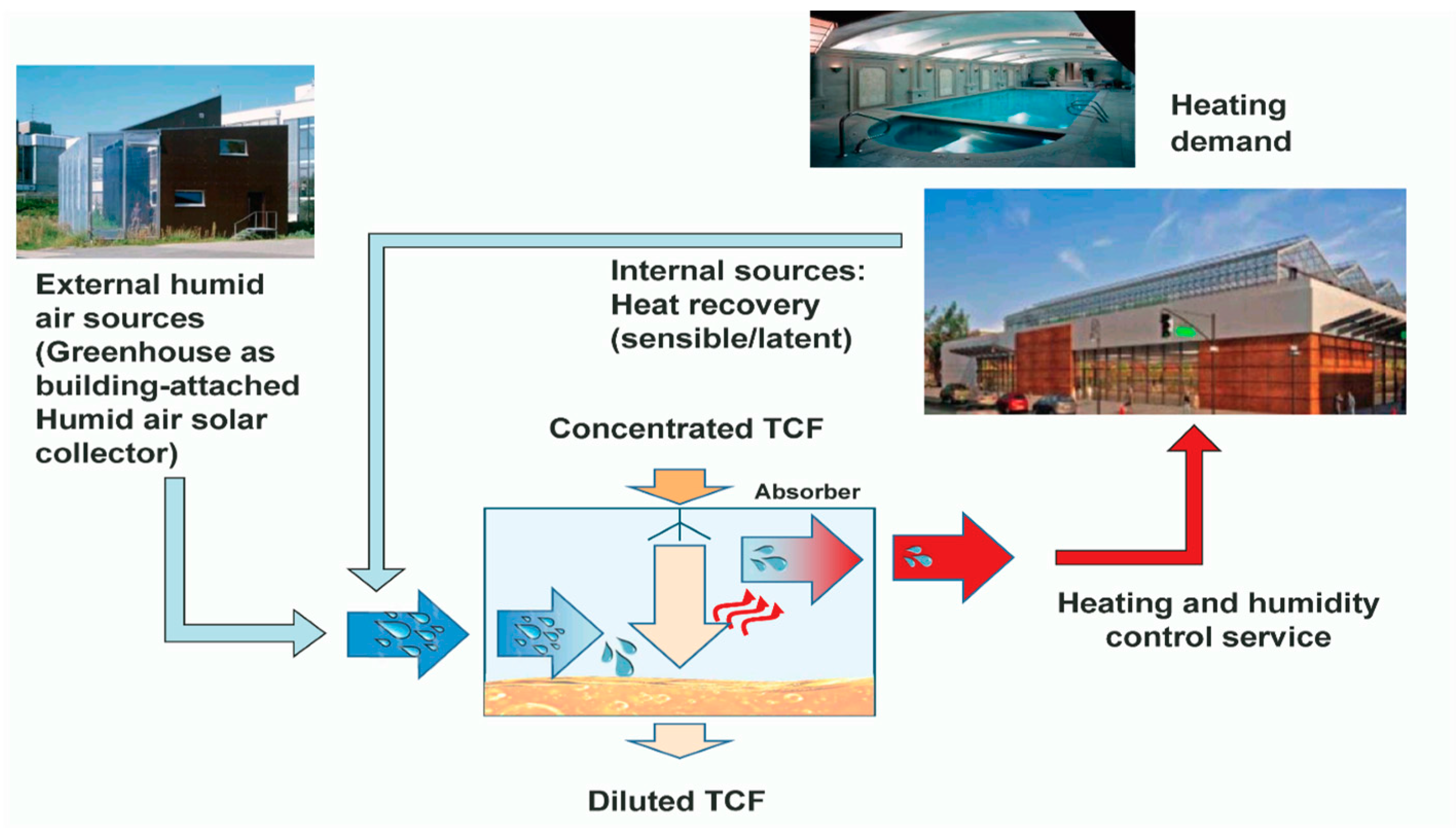
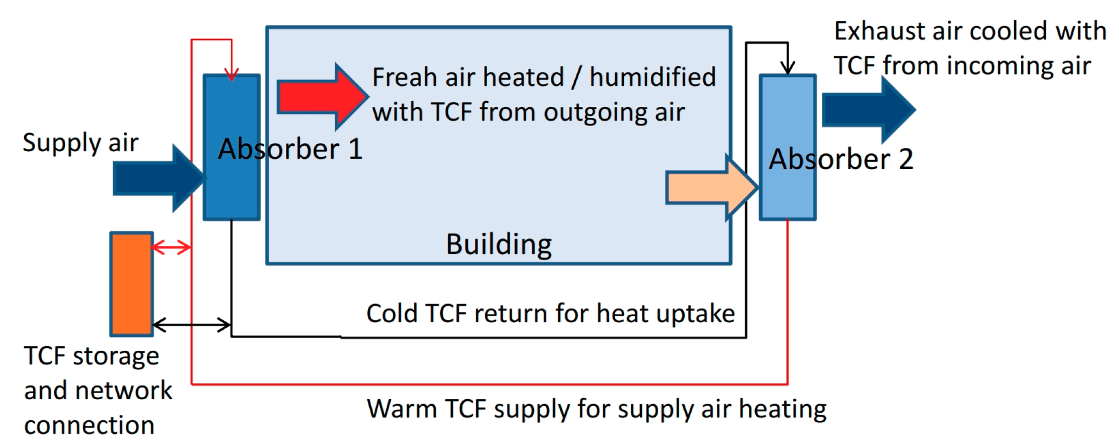
The heating and heat recovery scheme (Figure 4) relies on internal or external humidity sources. In the case of an externally-driven heat source, the absorption effect leads to a heating system transporting heat from the external source inside the building following the principle of a heat pump. Latent heat recovery is possible if internal humidity sources are present. In this case, the energy previously used to transform heat to humidity is converted back to sensible heat in the absorber. Furthermore, using two devices, latent and sensible heat recovery is possible using one device for the outgoing airflow absorbing humidity and heat and one for the supply air flow, providing heat and humidity from the thermochemical material to the air, thus allowing for comfortable indoor air conditions.
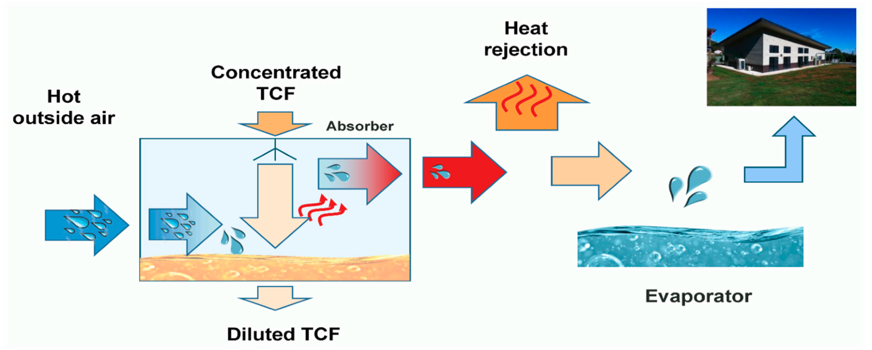
The cooling process relies on evaporation cooling. As prerequisite for evaporation, first, air is dried by absorption and the resulting heat is then rejected by a heat exchanger to the outside of the building (Figure 5). The dry air of moderate temperature is then ready to generate cold by evaporation.
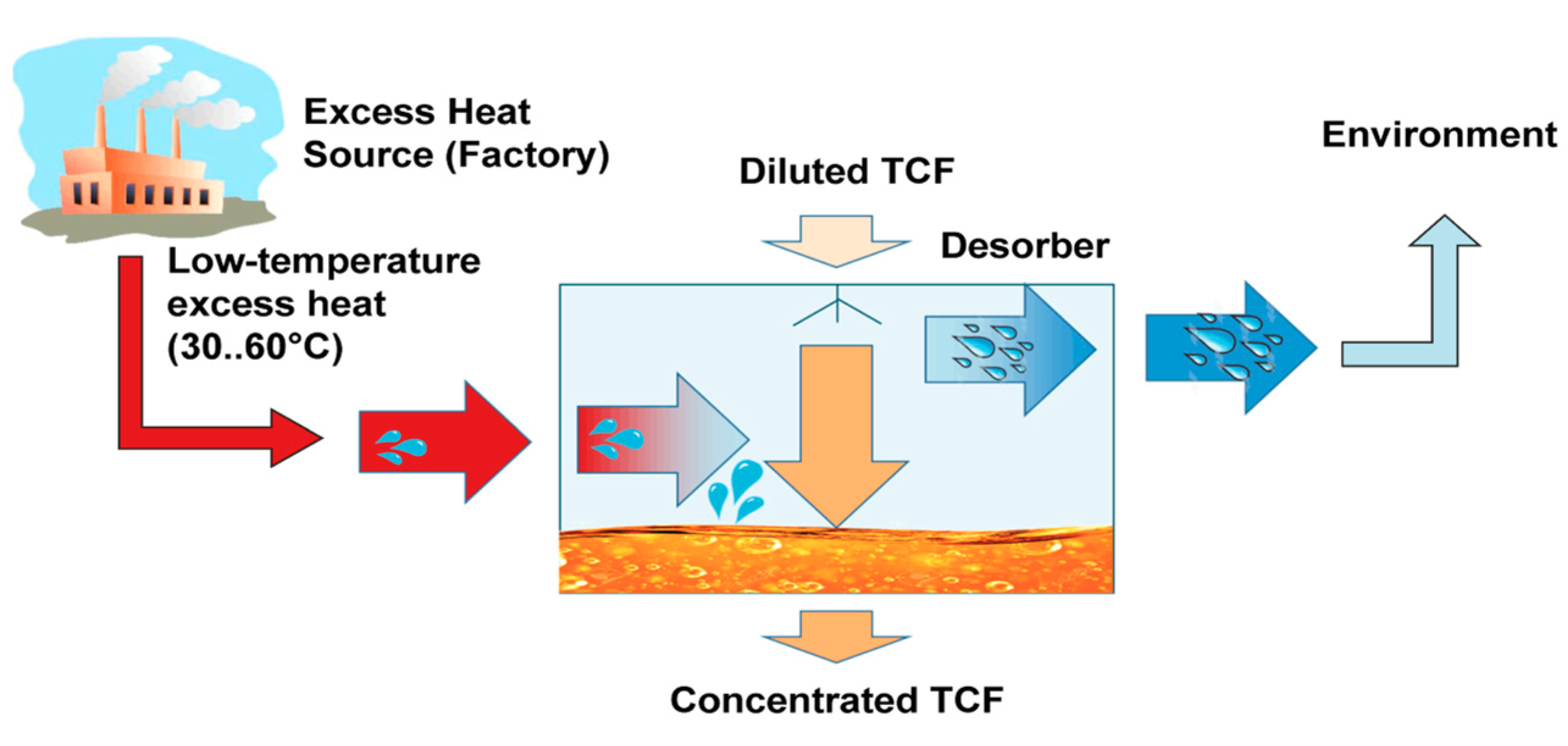
If the TCF has provided these services it has absorbed certain quantities of water and is diluted. Consequently, regeneration is required, which is provided by the process of desorption on the supply side of the network. This process again requires 680 kWh/t of water removed from the TCF. The regeneration takes place with excess heat, as shown in Figure 6. Low-grade excess heat can serve the regeneration as a fundamental advantage of this technology.
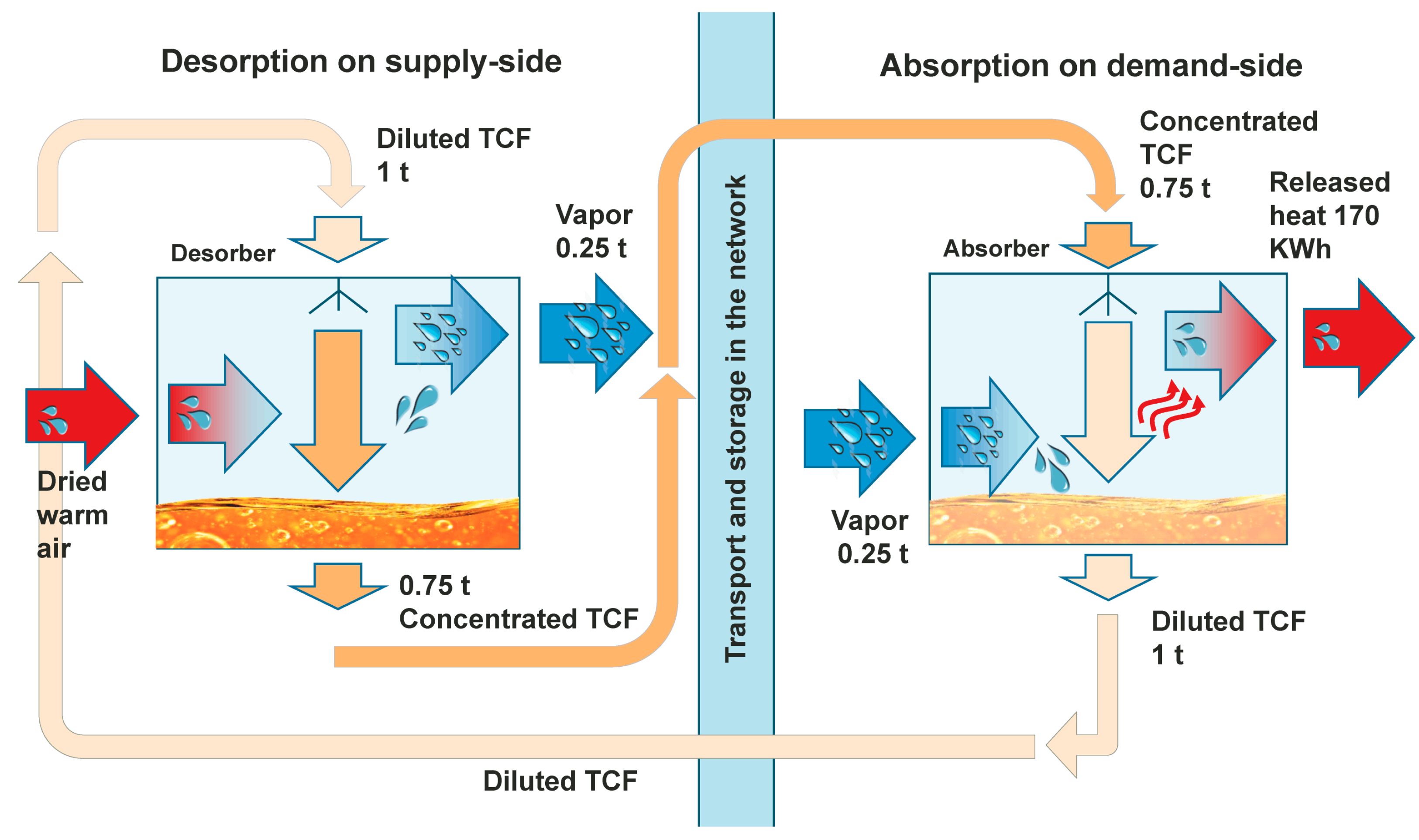
The combination and connection of both processes with their service form the thermo-chemical network as it is shown in Figure 7. The concentrated TCF from the regeneration process is transported via pipes in a network or other means of transport (truck, ship, etc.) to the location where the services are required. After providing this service, the diluted TCF is sent back for regeneration. The network features transport and storage free of thermal losses.

2.2. Absorption Technology Implementation

Main components within a thermo-chemical network are absorber and desorber facilities. Both are combined heat and mass exchangers that enable effective air-to-TCF contact. The facilities can be compared to a cooling tower in that water gets in contact with air and releases sensible and latent heat to the air. An absorber works in the opposite way, by taking up humidity and releasing thermal energy to the fluid. A desorber works similarly to how a cooling tower evaporates water with excess heat; however, the main product is the resulting concentrated TCF, while heat release can be an additional service (in the case of heat rejection, e.g., to minimize heat pollution to a river or lake) or has to be minimized in the case of exploring a limited heat source. Three different factors need technical consideration: (1) air relative humidity, (2) TCF salt concentration and (3) temperature (TCF and air). All factors are highly dependent to each other. The so-called TCF equilibrium humidity is a material property describing the point, at which at a given TCF concentration level a specific air relative humidity will be provided, if the TCF gets in contact with air. This means that air with a relative humidity above the equilibrium level (“humid air”) will be dehumidified down to the level of the equilibrium, while air below this level (“dry air”) will be humidified up to the equilibrium state. In the first case, the process is called absorption and, in the second case, it is called desorption or regeneration.
There are different ways to design and operate the devices depending on the goals of efficient use of thermal energy, the reduced need for liquid pumping and air ventilation, as well as a reduction of the device volume. Basic configurations include counter flow, parallel flow and cross flow between gas and liquid streams, as well as adiabatic and non-adiabatic characteristics. A specific design that avoids the formation and withdrawal of droplets is required to hinder salt outtake from the system, which would cause material losses but would especially result in corrosion problems within the airflow downstream of the device. Figure 8 shows examples of such a design developed in the H-DisNet project [2].
Specific requirements for the absorber include a maximization of the contact time between air and TCF, which allows to exploit the absorption potential well while minimizing the pumping power. This requirement is relevant as soon as drying or humidity control has priority. It is best met by absorber designs that retain the TCF for a long time, such as fleeces or similar, allowing low liquid flows. Furthermore, the utilization of the thermal capacity of the TCF is relevant for use cases in which heating or cooling is performed using the TCF to transport the heat. In this case, higher liquid flows are determined by the low thermal capacity compared to the thermo-chemical potential.
Requirements for the desorber include designs with a direct supply of heated air as the thermal energy source. Direct hot air supply in contact with the TCF can be provided, e.g., from exhaust air from data centres or building exhaust air with low humidity, or at least with fluctuating periods of low humidity. Hot air can also be generated by industrial processes, in which a stream of hot air is disposed to the outdoor environment as part of a process of space cooling or fresh air supply. Hot air can also be provided by a heat exchanger heating up ambient air to undergo corrosion problems within heat exchangers in direct contact to the TCF or, in the case of exhaust gases or highly-polluted air, which could cause TCF degeneration (e.g., high concentrations of sulphur dioxide). A further design uses heat from a liquid cycle, which is directed to the TCF via heat exchangers with specific coatings or plastic heat exchangers. If process cooling is not the main issue within the desorption process, a maximum use of the thermal capacity of exhaust heat may require heat recovery within the air flow downstream of the device in order to shift heat back to the air flow upstream of the device.
The criteria for the candidate substances of the TCF are hygroscopic properties, toxicity, cost and lifecycle environmental impact. Among the current TCF candidates are magnesium chloride (MgCl2), calcium chloride (CaCl2), calcium nitrate-ammonia nitrate Ca(NO3)2-(NH4)(NO3) and calcium nitrate Ca(NO3)2.

3. Use Cases of Thermo-Chemical Networks

3.1. Methods for Determining Use Cases

This section describes how thermo-chemical technology can be used to provide services. It follows the Systems Modelling Language (SysML) [3] and presents the information as use cases in requirement diagrams. The aim is to understand the specific conditions under which the technology will be applied. Additionally, simple schemes explain the processes that take place. Furthermore, estimations on energy consumption and assessment of the technological feasibility outline the potential of each use case.

3.2. Use Case 1: Humidity Removal and Heat Recovery Ventilation

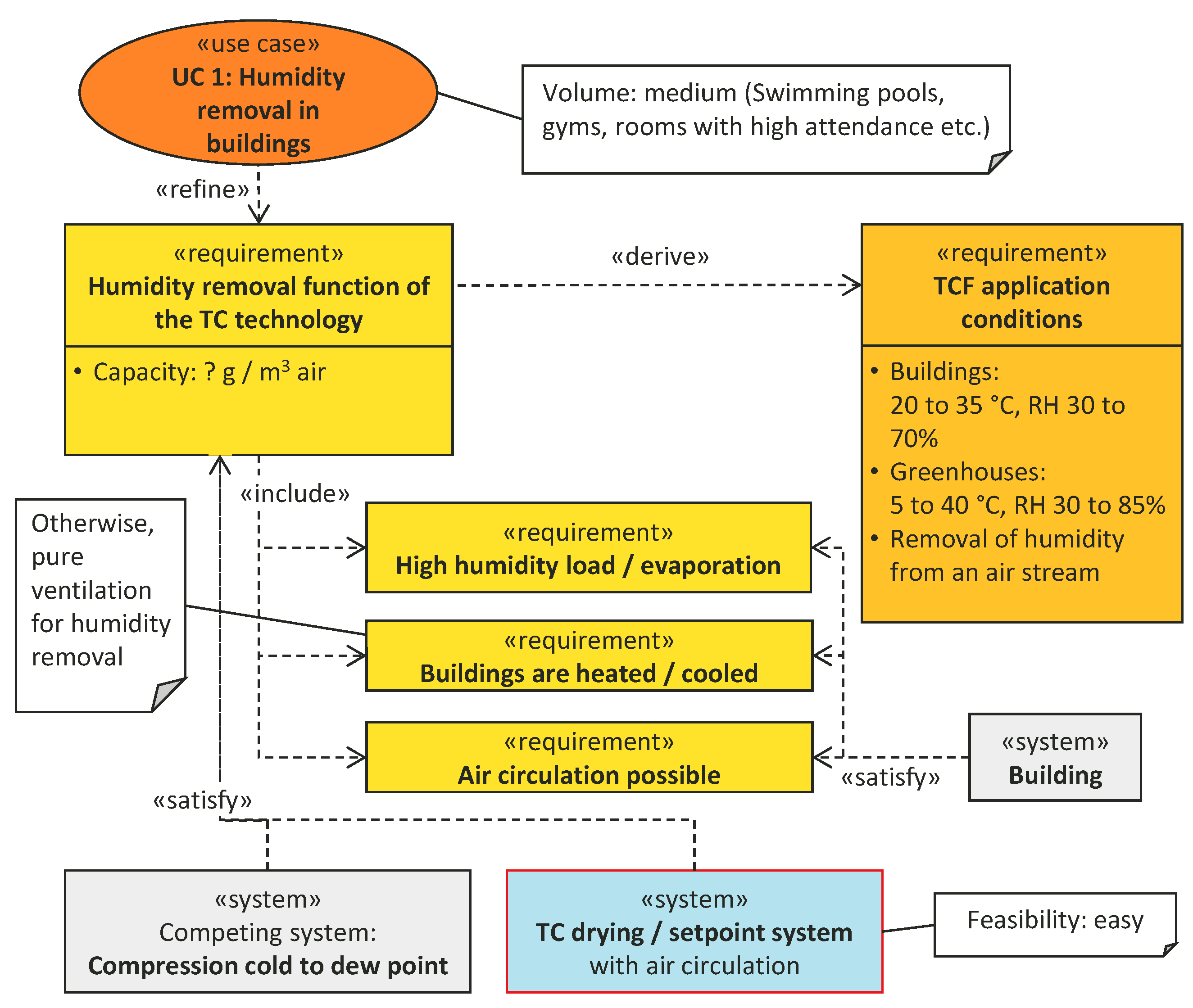
The case of humidity removal is related to buildings with components that continuously evaporate water and require its removal. Typical cases can be found at swimming pools, sport facilities, greenhouses, or rooms with high attendance, such as classrooms and lecture halls. However, humidity control in buildings is a function which is more and more required within highly-sealed modern or refurbished buildings. Humidity removal is normally combined with heating and/or cooling efforts, in which lowered ventilation also contributes to lowered energy losses. Additionally, cases that use compression cold to force condensation as a means of de-humidification are of special interest as the TCF-driven dehumidification can be applied at increased dew point temperatures and, by this, at substantially lowered energy demand. As a general operation mode, internal air circulation needs to be possible as a basic function to allow direct conversion of humidity to sensible heat. Figure 9 and Figure 10 show closed air circulation, open humidity removal and heat recovery.

3.2.1. Application Conditions

Typical applications, as shown in Figure 11, occur first in buildings, such as the cases mentioned above, in which humidity needs to be removed from an air stream at 20–35 °C and a relative humidity (RH) 30–70%, which results in absolute humidity (AH) of 5–22 g/kg. The second case are greenhouses with a bit extended range with 5–40 °C, 30–90% RH and 6–46 g/kg AH.

3.2.2. Estimated Volume/Impact, Potential and Feasibility

The feasibility of this application of the technology is easy because the removal of humidity is a direct capability of the thermo-chemical technology. Humidity absorption takes place as soon as the concentrated TCF is brought into contact with air. Heat recovery is realized by the sensible heat transfer that takes place at the same time. This includes sensible heat that is recovered from the humidity in the absorption process.
Taking into account electricity-driven compression cooling as the state of art for air dehumidification, a high potential in increasing primary energy efficiency exists in these cases. With the new technology, the amount of 680 kWh per ton of water needed for forced condensation can be provided by 680 kWh of residual low-temperature heat instead. A side effect of using a concentrated salt solution is avoidance of hygienic problems in air handling units, which is a problem for water-based humidification but also for matter accumulation on air filters and air to air plate heat exchangers. Both facts lead also to economically beneficial potential as maintenance costs can be reduced.

3.2.3. Limits

A limitation is that return air relative humidity (RH) is limited to the equilibrium humidity at given TCF concentrations depending on specific TCF material properties (e.g., ~35% RH with MgCl2 concentrate). To remove a scheduled quantity of water vapour, the air flow rate needs to be set accordingly. This can result in higher air circulation rates compared to conventional heat recovery ventilation.

3.3. Use Case 2: Buildings, Humidity Set Point Control

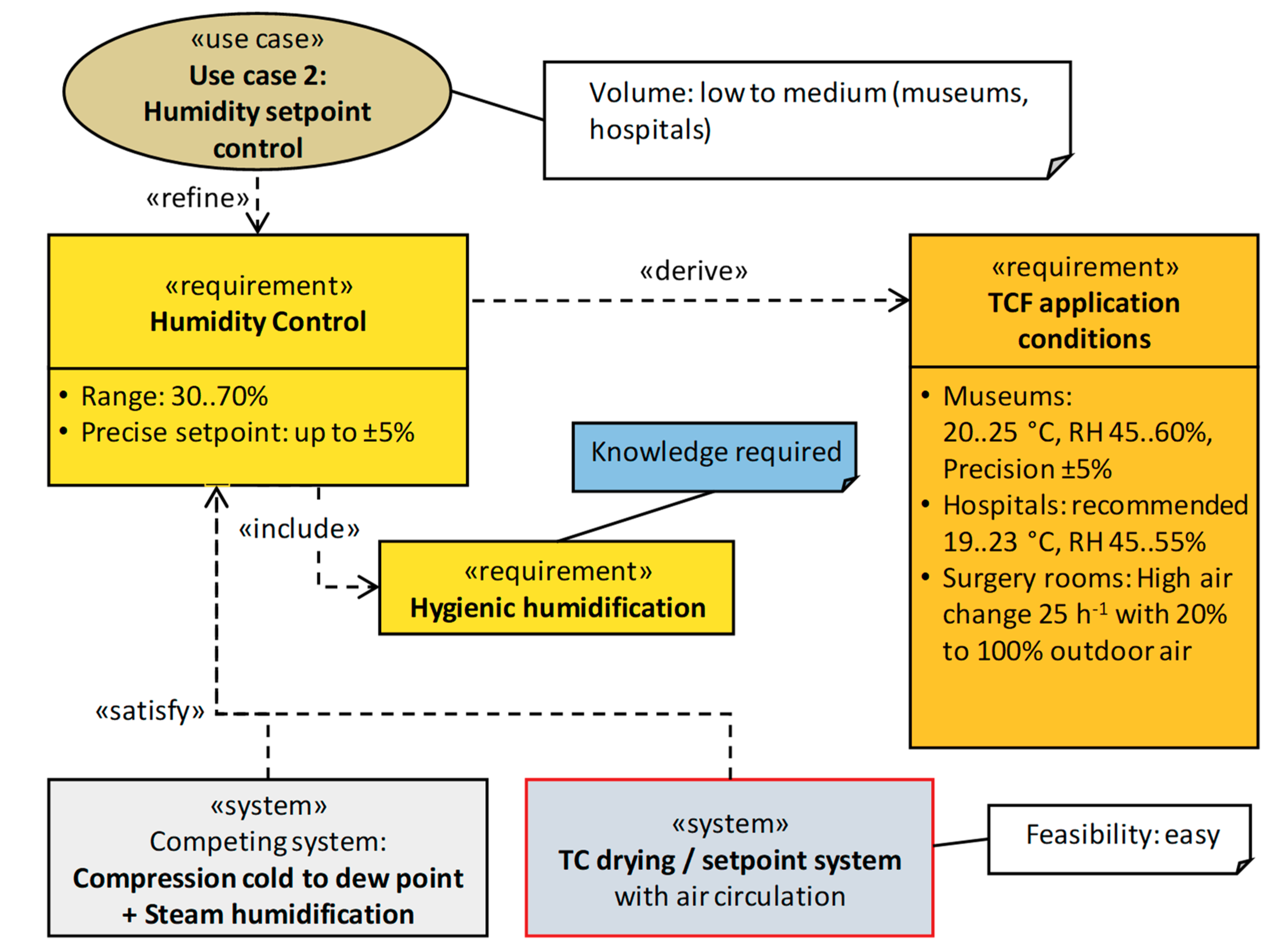
This use case deals with indoor spaces that require dehumidification or humidification to maintain humidity in a specific, defined range, such as occurring in museums, hospitals and specific workshop and production environments. Such buildings are equipped today with several different interacting installations, such as humidifiers, de-humidifiers, heating- and cooling devices, that consume much energy. Typically, dehumidification is achieved by dew point cooling and humidification by steam production. A thermo-chemical system can serve all these functions in an energy efficient way with only one air to liquid direct contact heat and mass exchanger. In general, dehumidification does not need cooling but is provided by the hygroscopic property of the TCF that is driven by low-grade excess heat. Humidification does not need water sterilization by boiling as salinity of the TCF hinders biological activity. Salinity is expected to improve air quality, thus providing a further benefit.

Operation Scheme/Estimated Volume/Technology Impact and Feasibility

The system requires an internal air circulation mode as well as an air exchange mode to provide a maximum of different control varieties. It operates in the same way as shown in Figure 9 for humidity removal in Use Case 1. Therefore, the feasibility of the system is also relatively easy. As shown in Figure 12, typical operation conditions in museums are 20–25 °C at RH 45–60% with high precision (typically only ±5%) [4]. In hospitals, the recommended ranges are 19–23 °C and RH 45–55% [5]. Due to the required humidification, during heating periods an extra radiator may be required in both cases to provide any combination of temperature and humidity, as heat provided through the TCF also triggers (increases) the humidity. The volume of cases and the total energy consumption is low, even lower than in the first case as the amount of humidity to be converted is lower. In contrast, by its simplicity, the thermo-chemical technology will significantly reduce efforts for installation and maintenance.

3.4. Use Case 3: Building, Space Heating

Heat demand for space heating is estimated to be about 11,700 PJ/a in Europe [6]. In comparison, the total amount of renewable power in Europe accounts around 3600 PJ/a [7]. Although retrofitting measures will reduce this volume, this use case involves the highest amount of energy consumption. In contrast, the application of the technology is more complex than use case 1 and 2. Therefore, we will first discuss a simple form of the use case focusing on heat and humidity recovery (Use Case 3.1) and secondly a variant providing also heating (Use Case 3.2).

3.4.1. Use Case 3.1: Conventional Heat Source Plus Desiccant-Based Heat Recovery

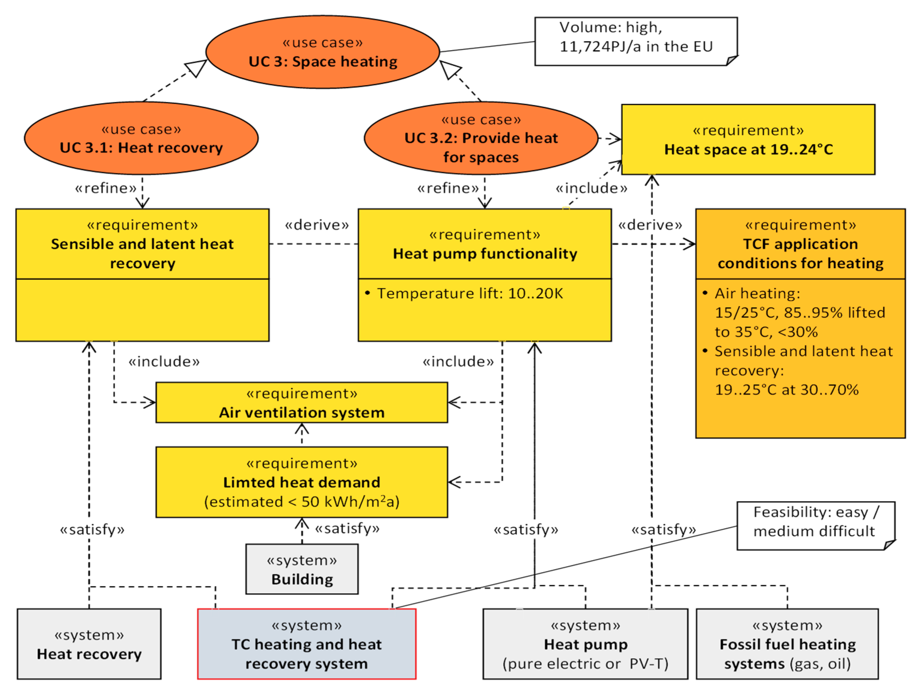
As building heat supply is the main function provided by thermal networks, this use case is of high importance. Its requirements are shown in Figure 13. There are several specific benefits of heating under the use of desiccants:
  • Heat is provided to air through the TCF in direct contact. Operation with only one heating device leads to increased economic viability.
  • A large contact surface allows placement in a compact box with reduced investment costs compared to state of art low temperature radiators, such as floor heating systems.
  • Heat is provided by the absorber, allowing combined heating and humidity control (humidification and de-humidification) within one device. The humidity rate is controlled by the salt concentration.
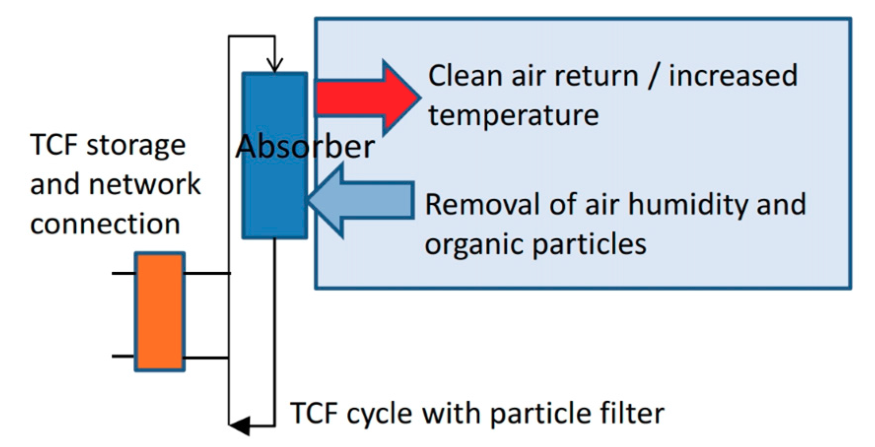
  • Internal air circulation mode allows reconverting humidity from internal sources to sensible heat directly. Furthermore, the air is filtered, as the TCF also removes particles, such as dust and organic compounds. Due to combined humidity control and air filtering, a total reduction of air exchange is possible, which in turn reduces the ventilation energy demand.
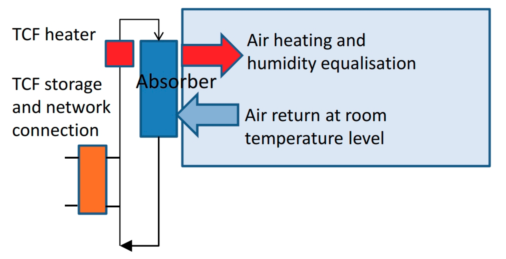
As a direct supply of heat through TCF also leads to a related air humidity (dependent on salt concentration), supply temperatures have to be sufficiently low excess humidity rates in the room. By this condition, it provides its essential benefits mentioned above in the category of buildings with limited heat demand (estimated < 60 kWh/m2a) and low temperature heating systems. Air distribution systems are required in larger rooms to prevent effects of by-pass air flow. Nevertheless, for heat and humidity recovery, supply and exhaust air channels of the thermo-chemical system do not have to be at the same place. This is a substantial advantage against conventional recovery units, such as plate heat exchangers or solid desiccant wheels that require air streams and required duct work to connect to one unit at one location in the building. These requirements often exclude such functions from residential buildings. In contrast, the decentralized configuration of thermo-chemical systems allows for air flows through the building, thus also limiting the need of air circulation infrastructure. The first method of operation is the recirculation of the air, as shown in Figure 14.

3.4.2. Use Case 3.2: Heat Supply with Additional Low-Temperature Heat Source, Heat Pump, TCF-Driven Latent Heat Uptake

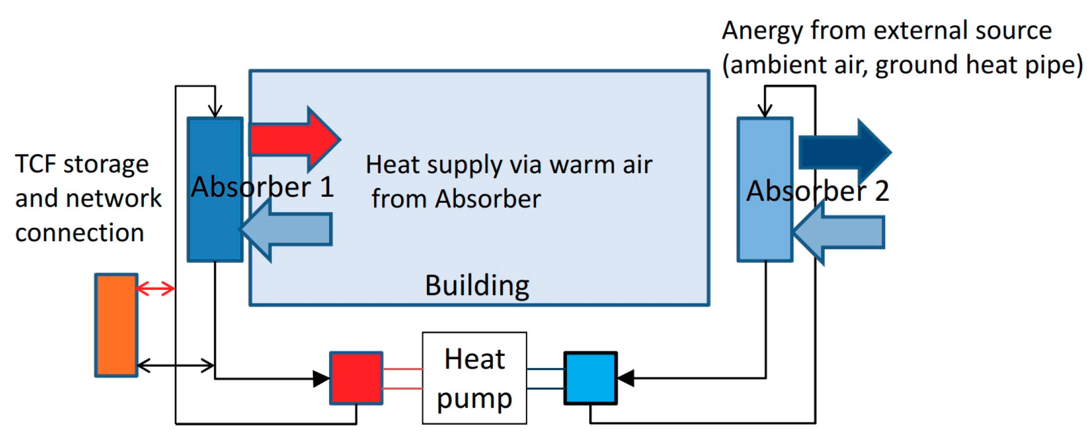
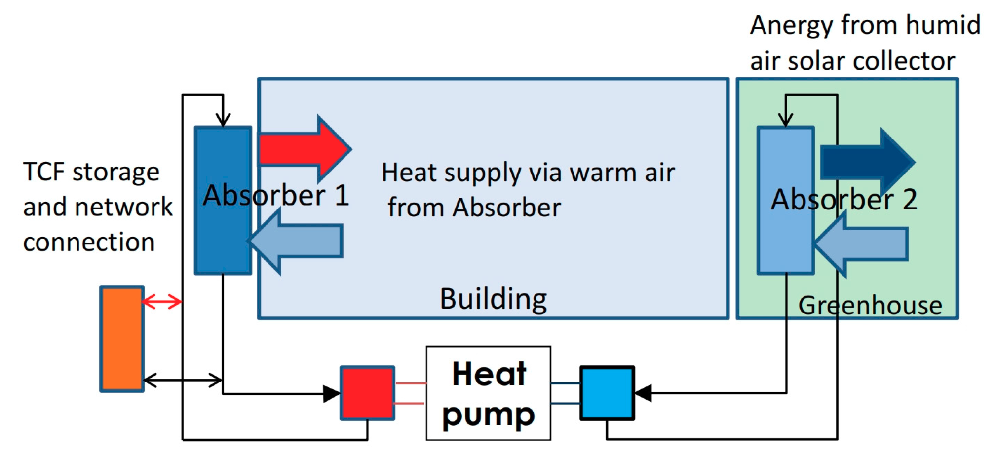
In addition to internal sources, low-grade heat from external sources can be integrated into building energy systems. At this moment, the system turns into a heating system. The system works best if a heat pump is integrated to support the process. The TCF allows heat and humidity uptake from the external source in direct contact with air. Figure 15 and Figure 16 show different possible schemes for this operation mode. Low-energy buildings with a limited heat demand (estimated < 60 kWh/m2a) constitute as ideal candidates for the resulting low-temperature heating system. Local energy (low-temperature heat sources), e.g., from a greenhouse, as humid air solar collector, geothermal heat, or from a thermal storage (e.g., seasonal storage), is explored using the heat pipe effect of evaporation and condensation. The heat pump best uses the heat source with highest enthalpy available. A control system chooses, e.g., between (1) building exhaust air, (2) greenhouse air, (3) heat from storage and (4) from the environment, allowing to run the heat pump at its best efficiency. A demand-side TCF-based thermal storage allows to provide heat below 0 °C, as the salinity of the TCF lowers the freezing point down to −30°C depending on the concentration. The heat pump combined with the thermal storage allows linking to smart grid applications and makes the system a very flexible electricity consumer.
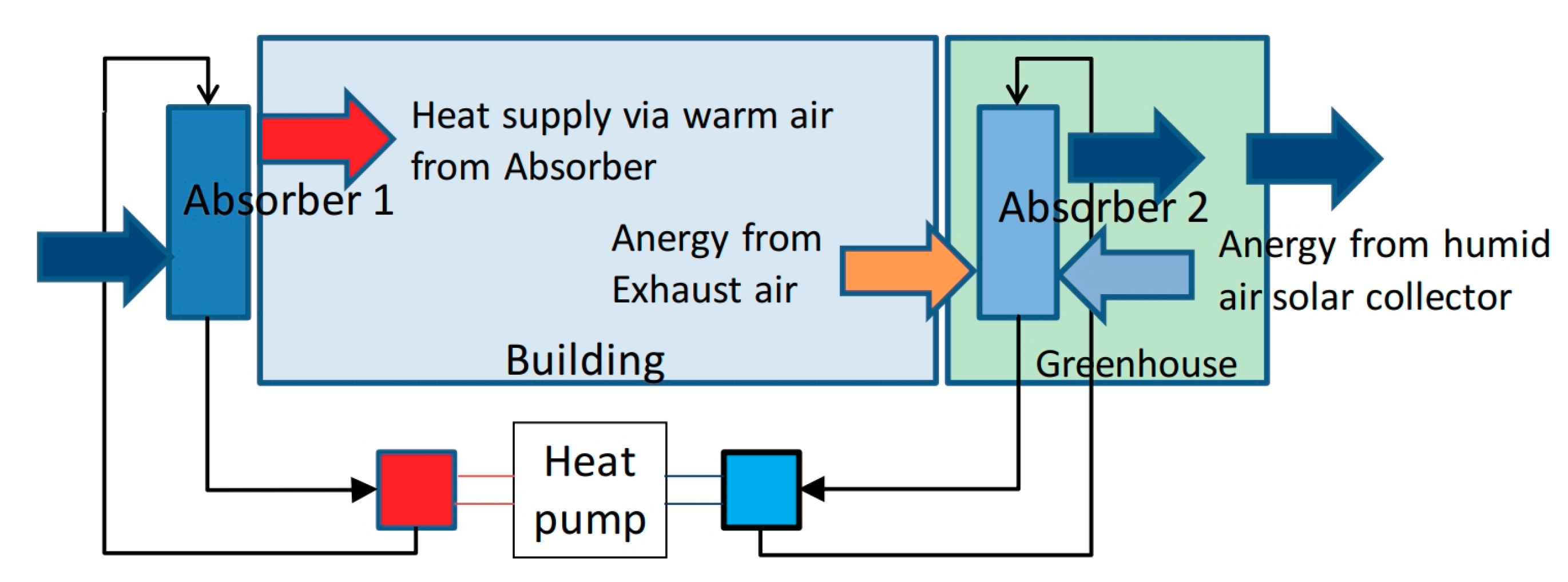
The integration of humid air solar collectors works most efficiently during the interim season and during sunny winter days, while there is a remaining weak efficiency during longer cold periods without sun. Figure 17 shows a scheme for the application of the technology for this purpose. However, if used in combination with a long-term or seasonal thermal storage it will strongly reduce the total storage volume. Furthermore, temperature lift is limited (5–15 °C, depending on the TCF) and the heating temperature is limited to about 30 °C to avoid excess humidity in the building. Typical conditions are a temperature lift from 15–25 °C with RH 85–95% to up to 35 °C with a RH of less than 30%. This makes larger airflows required then necessary for ventilation. These airflows limit the available heating power, which is shown in more detail in the simulation in Section 5. This limitation requires low-energy buildings for the system’s successful implementation. Otherwise, additional radiators (e.g., existing radiators in refurbishing) allow solutions for higher demands.

3.5. Use Case 4: Space Cooling and Air Conditioning

In addition to heating, space cooling is a second important consumer in the energy sector. It is expected to consume 2500 PJ/a in Europe by 2020 [7]. Similar to space heating, a simpler use case focusing on humidity control in space cooling (Use Case 4.1) and a more complex and comprehensive one providing the full service has been identified (Use Case 4.2). Figure 18 shows the details of these two use cases.

3.5.1. Use Case 4.1: Humidity Control and Cold Transfer for Space Cooling

Space cooling usually also requires dehumidification to ensure comfort in buildings and to prevent humidity damages. Like the use cases of humidity removal and control, this is done by cooling the air down to the dew point. This is quite energy-intensive as the heat pump has to remove the heat and the condensation energy amounting to, again, 680 kWh per t removed water from a relatively low-temperature level (5–10 °C) to a typically high outside temperature (25–40 °C). This causes heat pumps to run at a poor COP to remove a large amount of heat, usually electricity-driven. If dehumidification is performed thermo-chemically one major part of energy (for de-humidification) then is removed driven by excess heat. Furthermore, the heat pump needs only to cool down the air to the supply temperature for the building (15–20 °C), which improves the COP so that theoretically up to 50% of energy could be saved. Moreover, cooling infrastructure can be combined with heating functions within one integrated device, thus, lowering the overall investment costs. Figure 19 shows a scheme of a system coupling a heat pump with a thermo-chemical dehumidification system. Operation of the thermo-chemical technology in this case is typically at 15 °C and RH 40–60%, leading to comfortable conditions of about 25 °C and RH 20–30% in the building.

3.5.2. Use Case 4.2: Provide Cold Air and Air De-Humidification

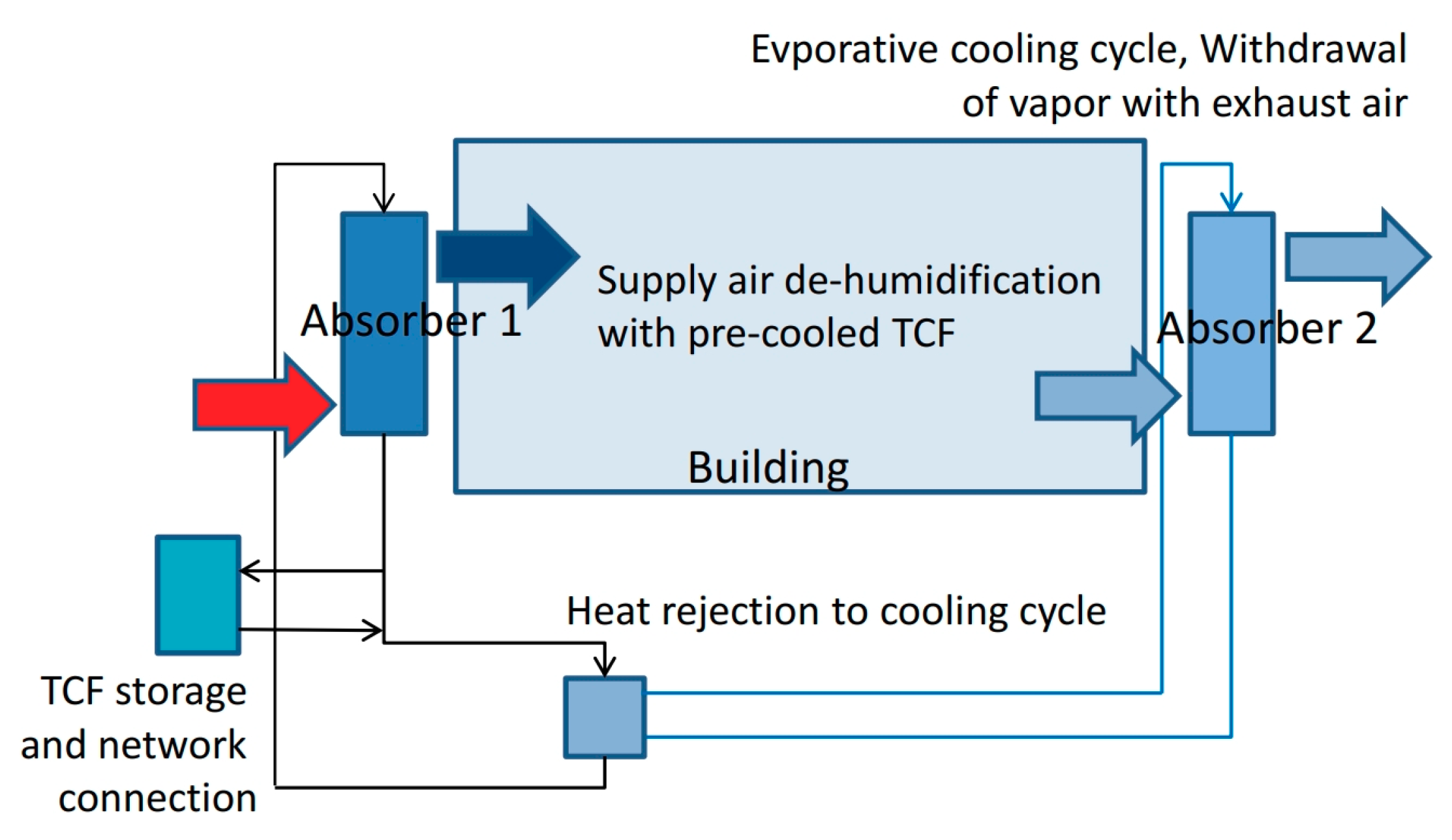
The heat pump can be replaced by evaporative cooling. By this, the function is limited to buildings with low cooling power demand (estimated up to 40 W/m2 peak), reached by passive functions like external sun screens, wall and window insulation and architectural measures of window placement. The function of water evaporation is placed in the exhaust air stream. This allows keeping the scheduled temperature range below 20° and to move water vapour to the ambient air, while indirectly providing the generated cold to the building through the TCF, which acts as a heat exchanging medium. The cold TCF can be used for both temperature control and air de-humidification of supply air. Figure 20 shows the scheme for the evaporative cooling supported by thermo-chemical technology. Typical operation states of the system are indoor conditions of 24 °C and RH of about 50–60% to evaporate water in the outgoing airstream. This requires thermo-chemical drying of incoming air which brings the air to about 35 °C and RH of 32%, which is 60% at 24 °C. Heat from this process is also rejected with the outgoing air.
However, the temperature reduction of evaporative cooling is limited and depends on air properties entering the process (temperature and humidity). Due to this fact, higher air volume flows are required leading to the power limit above mentioned. Therefore, evaporation of water to the environment also needs to be allowed in terms of hygienic conditions. If a TCF is also used for evaporation cooling this is expected to improve the hygienic conditions making the technology also applicable in dense urban areas.

3.6. Use Case 5: Industrial Drying

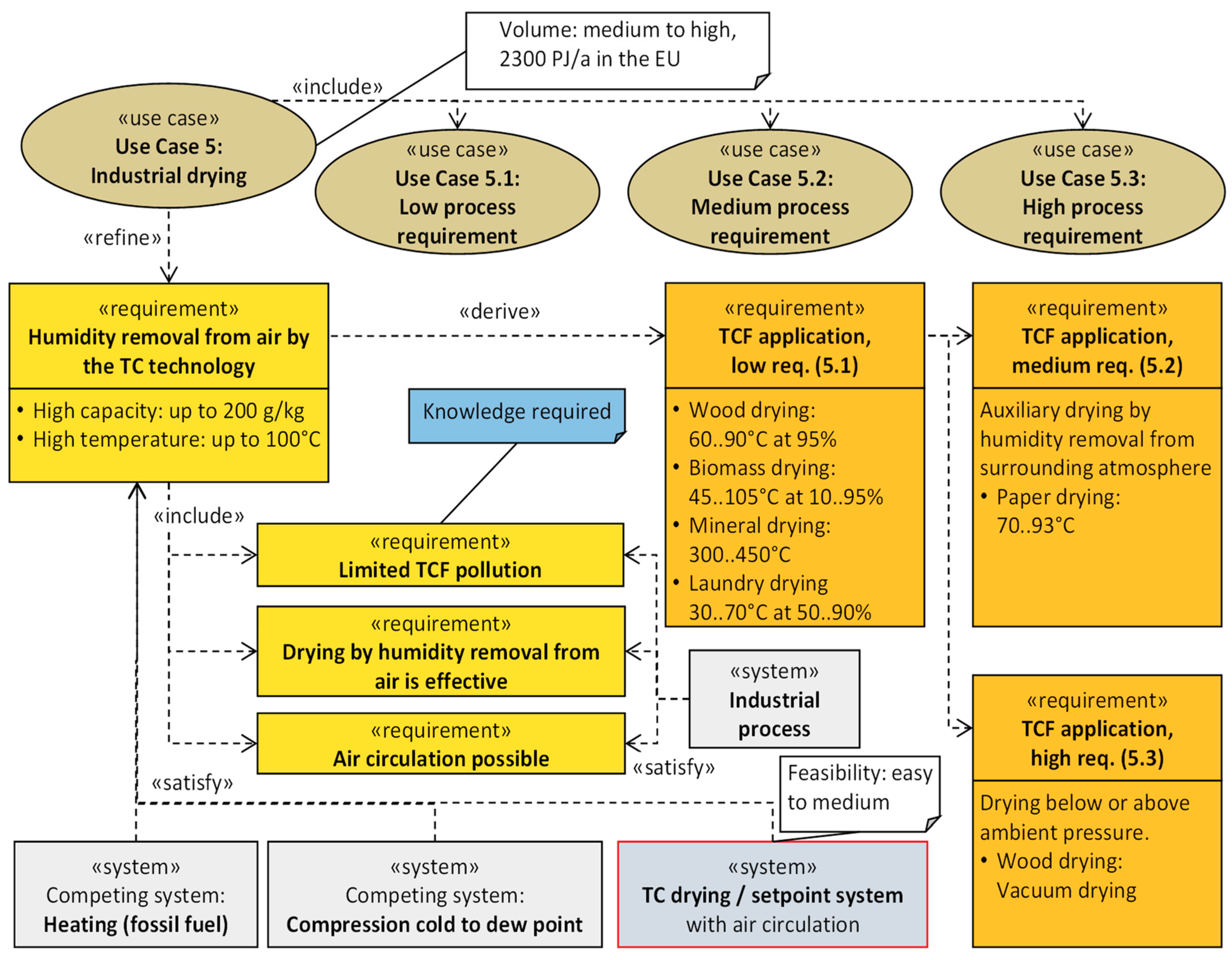
The total primary energy demand in industry in the EU is about 26,000 PJ/a. A significant share of this energy is required for drying processes. In UK, this share is about 9% (UK Government 2013). Extrapolating this share leads to an estimation for the EU’s primary drying energy demand of about 2400 PJ/a. This represents a large potential as drying is the simplest application of thermo-chemical technology. However, it requires consideration of specific processes as described in [8]. We differentiate three different use cases of drying in terms of their requirements, as shown in Figure 21, which are described in the following text.

3.6.1. Industrial Drying with Low Process Requirements

A simple drying mode works without an additional heat source and supports natural drying. Slight temperature differences, caused by absorption and evaporation processes, are driving the system. It may be used for maintaining humidity rates in material storage and in simple drying processes, where sufficient time and space for the device is available. This is mode applicable for drying of biomass, wood pellets/firewood, bulk construction materials, raw materials (chemical/metal) and domestic laundry drying. The energy requirements are reduced to process air- and TCF transport. In circulation mode, a maximum use of the thermo-chemical potential is provided, as all water goes to the TCF material, while the involved released sensible heat is returned back to the drying good. The absorption process can be driven in a separated chamber or directly within the drying chamber with natural air circulation only. For set point humidity applications, TCF concentration can be controlled by the air flow rate or by TCF concentration. Furthermore, raising the temperature increases the humidity capacity of the air which speeds up the process. In recirculation mode, the heat sources have only to cover thermal losses whereas the much larger drying energy amount is covered by the thermo-chemical potential.
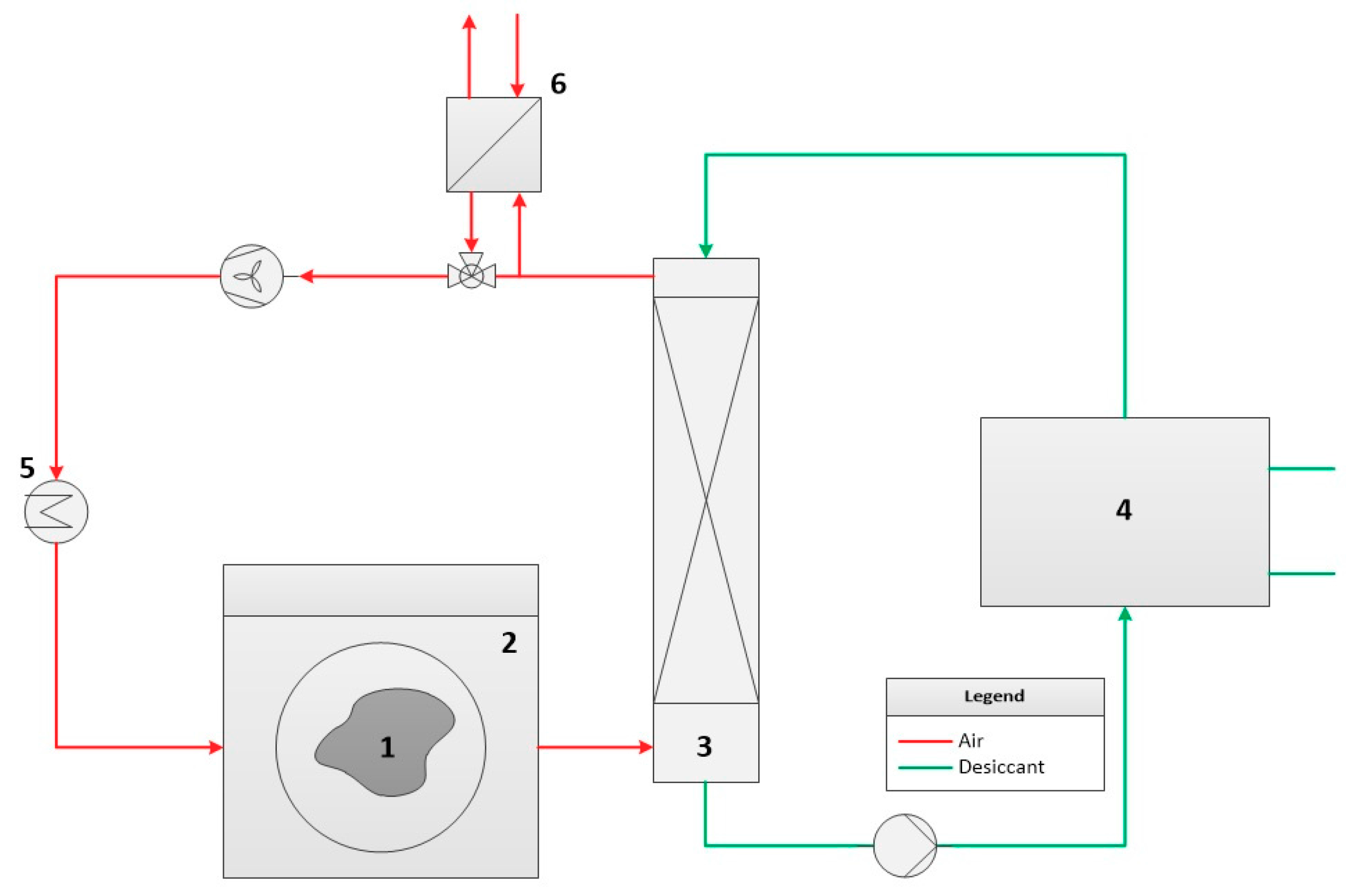
The conditions under which the low-requirement drying is operating are quite different (Figure 21, low requirements, 5.1). However, the scheme removing the humidity from the air around the drying goods is always similar. Figure 22 shows how it would work with thermo-chemical technology. Typical conditions, such as temperatures of 50–90 °C, exploit the high water capacity of the air.

3.6.2. Industrial Drying with TCF Heat Recovery and Additional Heat Source Medium Process Requirements

In the next use case of industrial drying, for technical reasons of drying processes, the drying demand is not only covered by thermo-chemical potential but also by additional heat sources. This case occurs in products such as Wood, textile, paper, food, chemicals/pharmaceuticals, cement, brown coal, gypsum, etc. In existing processes, the heat is provided to the air (convective drying) and/or to the material (conductive, radiative, dielectric drying). A thermo-chemical dryer will only contribute to the reduction of air humidity as heat released during the phase change is redirected to the air and not lost with the outgoing air. The lowered humidity and increased temperature in the air make the process more efficient and reduce the primary energy demand. By using a heat exchanger within the absorber element or within the TCF cycle, the heat released during the phase change can also be directed to an external heat cycle in order to redirect heat and to provide heat to the drying material directly. The system can support different drying devices, such as a vessel, tray, rotating drum, fluidized bed, or spray-drying method. The absorption process can be applied in a separated chamber or within the drying chamber with natural air circulation in order to reduce the ventilation energy demand.
Additionally, for medium-demand drying, due to many different technologies, the conditions differ a lot. However, the principle, which is a combination of thermo-chemically and thermally-driven drying is similar for all cases. A scheme is shown in Figure 23. Paper drying, which is a representative example, has quite a high share of energy consumption for drying 477 PJ/a given an annual production of 90 Mio t/a [9] and an energy use intensity of 5.3 GJ/t of paper [10]. Typically, paper is dried at 70–93 °C going over steam-heated cylinders [11]. Thermo-chemical systems can support this process by removing humidity from the air around the cylinders and converting it back to sensible heat.

3.6.3. Use Case 5.3: Industrial Drying with a Set Point Temperature and Humidity Control and Low-Temperature Applications (Higher Process Requirement)

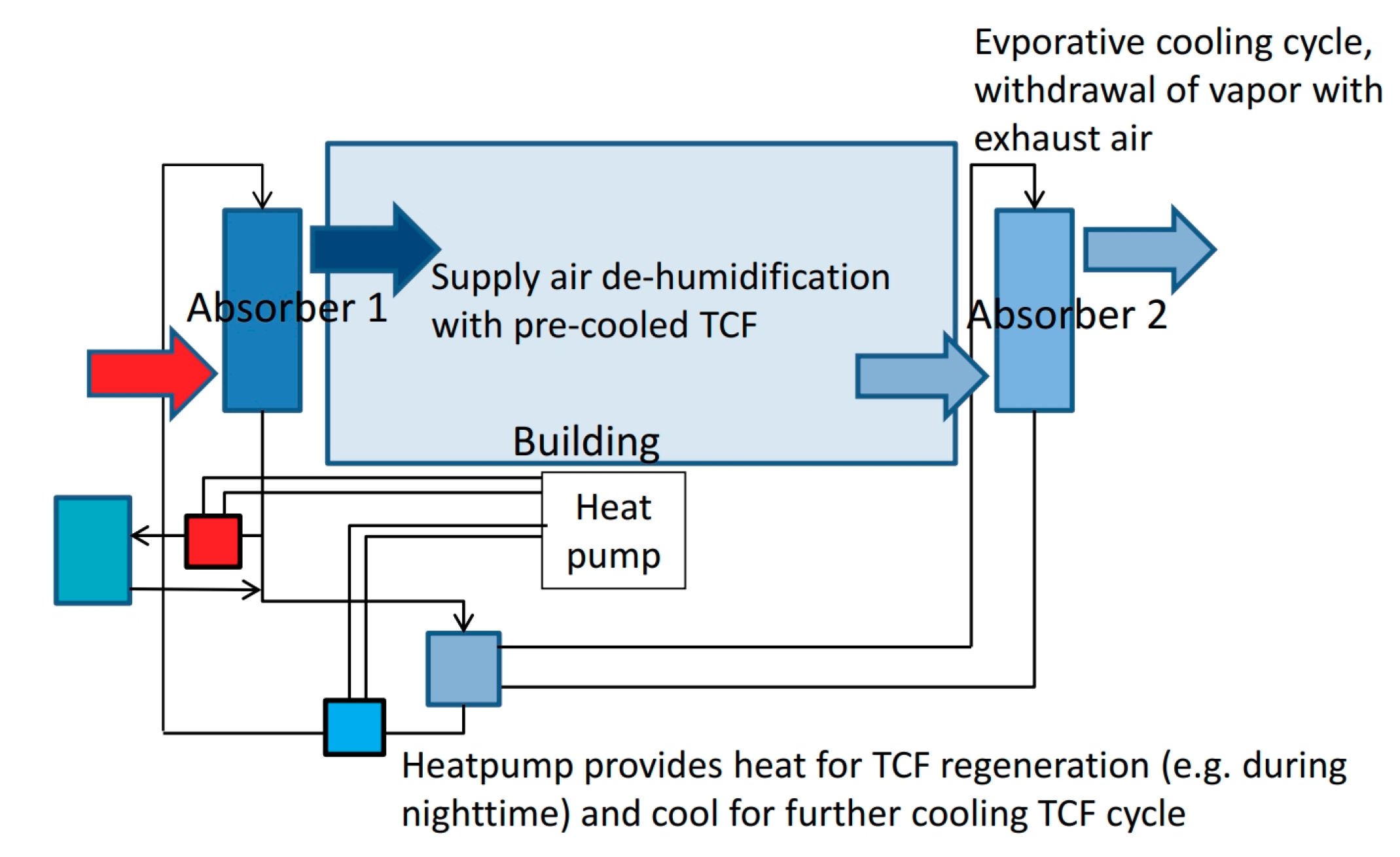
This use case includes applications that require humidity control and usually take place at lower temperature levels. In this case, the air humidity can be set below the equilibrium humidity of the TCF, allowing to provide a more specific control of the drying parameters. To provide a more specific combination of temperature and low humidity, an additional heat pump is provided, as shown in Figure 24. Cold is provided through the TCF, thus, also allowing an improved drying performance, while additional heat is provided to the air stream behind the absorber.
Within this case, also air temperature can be set under ambient temperatures, like in cold stores with set point humidity conditions. The dehumidification is provided by additionally cooling the TCF, while the heat from the heat pump is rejected from the system by an external cooler. In this way, drying applications of sensible material with specific temperature at low humidity conditions is possible. The materials are specific temperature sensible textiles, food, pharmaceuticals and high-tech materials with demand for specific low-temperature drying with high drying performance.
For all drying processes, there are some specific conditions for the application for thermo-chemical technology. It is necessary that no substances are emitted that will degrade the TCF or will accumulate in the TCF in a disadvantageous way. Drying times might be extended as air recirculation and TCF use can lead to higher humidities and there is additional space required for absorbers. Furthermore, the airflow needs in most cases to be increased, which might, together with TCF transport, result in higher auxiliary energy demand. Moreover, operational temperatures of the overall system are limited by the freezing point (MgCl2: −20 °C to −30 °C) and the degradation point (MgCl2: 120 °C).

4. Economics of Use Cases

Section 3 shows the possible services deliverable by the intelligent hybrid thermo-chemical district network technology. Depending on the climatic and required air-conditioning conditions, the replacement of the conventional competing technology (e.g., electrically-driven vapour compression, fossil fuel heating system, etc.) with thermo-chemical technology could result in economic benefits. Considering investment and operational costs, a comparison of the economics of conventional and TCF technology in five different use cases is performed here.

4.1. Methods for Economics of Use Cases

The cost-effectiveness of the replacement of conventional technology with TCF can be evaluated by the payback period, or simple playback (SP), which represents the time needed for the return on investment resulting from the employment of alternative technology for the specific use case identified in the paper and is defined as [12]:
SP =   INV , Cos t TCF   INV , Cos t VC OP , Cos t VC OP , Cos t TCF
where INV , Cos t and OP , Cos t represent the investment and operating cost of the considered conventional and thermo-chemical replacement technology, respectively. The performed economic analysis shows the possible economic savings resulting from the utilization of TCF-based technology instead of conventional for five use cases where it could see particularly favourable results, such as humidity removal in pools, humidity control in surgery rooms, space heating for low-energy buildings, space cooling in hot and humid climates and drying applications. This economic analysis does not want to investigate the cost related to the employment of hybrid thermo-chemical networks but rather the possible economic savings resulting from the use of TCF-related technology instead of the conventional technology in some specific cases.
An exhaustive analysis of the operating cost of conventional technologies should consider the electricity cost for operating the chiller and the associated equipment (e.g., cooling towers and circulation pumps) for cooling and dehumidification applications and gas costs for heating application. On the other hand, the electricity cost of TCF system is related to the electricity consumption for pumping the solution and blowing the air through the system and for the cooling tower.
The investment cost of the conventional system includes electrically-driven vapour compression cooling system cost, gas boiler cost and associated equipment [12], while the investment cost of the TCF systems is estimated based on technical papers of developing, manufacturing and/or selling liquid desiccant technologies [13]. As reported in [14], in the economic analysis an electrically-driven vapour compression cooling systems with a COP of 3.67 is considered. The reference cost of the system considered in the economic analysis is 280 €/kW, based on the quotation provided by the UK distributor Trane [14]. After an analysis of the market prices [15], the cost of conventional gas heater used in the analysis is estimated to be around 45 €/kW.
On the other hand, the investment cost of a TCF system used in the following economic analysis was estimated as 700 €/kW and 800 €/kW for large-sized and small-sized system (<10 kW), respectively [13]. The cost is comprehensive of capital and equipment cost. For the TCF technology replacement to be economically feasible, it should not be more expensive than the conventional technology over a 20-years lifespan unless significant benefits are offered.

4.2. Humidity Removal

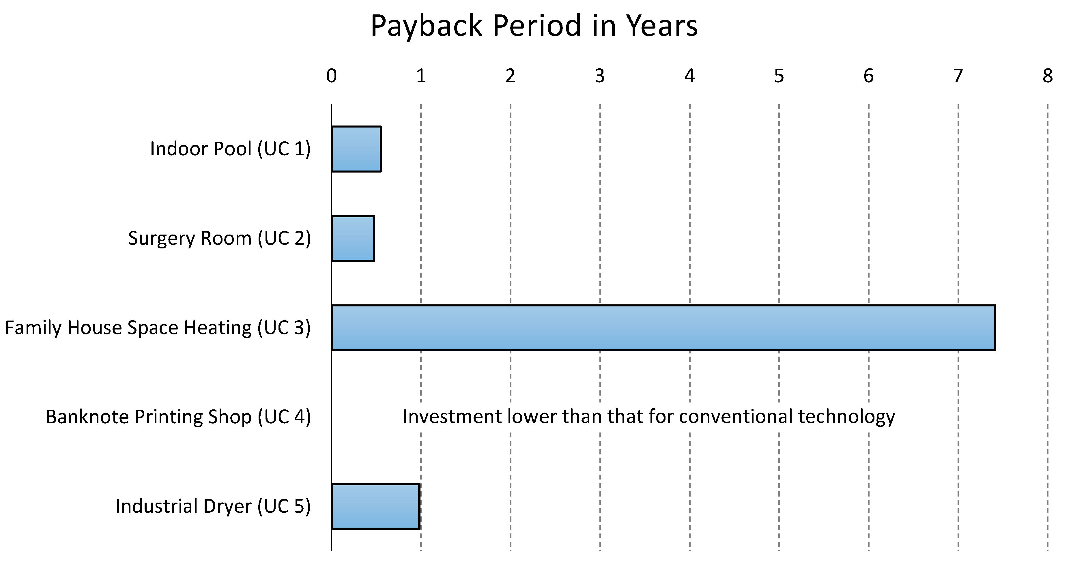
The first considered use case is the humidity removal in indoor swimming pools, described above as Use Case 1. Swimming pools are building characterised by continuous evaporation of water that requires being removed. This moisture removal process could be efficiently performed by TCF technology. Moreover, in the conventional system, the water evaporation in the pool requires consumption of energy to heat the pool and maintain its temperature constant. Taking this use case as a reference, for which market-ready technology exists that is not integrated in a network [16], an analysis of the possible economic savings resulting from TCF technology has been performed. In the use case, the feasibility of the replacement of the conventional technology with TCF technology for a 13.7 m × 22.9 m pool has been evaluated. The previous technological configuration was an 18,700 m3/h chilled water coil system, dealing with sensible (77.37 kW) and latent (51 kW) loads to control moisture and temperature inside the indoor pool [16]. The conventional technology used heating (41 kW) of air (5500 m3/h) to control the water condensation on the building windows. A water-to-water heat exchanger was used to provide up to 200 kW heating to the pool to maintain its temperature [16]. The employment of TCF technology could eliminate the need for air heating to avoid condensation and a massive portion of the heat used to warm up the pool. TCF technology for indoor swimming pools could directly use pool water to remove the heat, resulting in an overall system cost reduction caused by the absence of a cooling tower/chilled water unit to remove heat before the absorption process. The reachable annual savings resulting from the technology replacement were significant and estimated to be around 176,000 kWh [16]. Considering an electricity cost of 0.12 €/kWh, this results in a yearly economic saving of 21,100 €. For the conventional system, the cost of a 130 kW electrically-driven vapour compression chiller able to deal with the sensible and latent loads in the considered indoor swimming pool is around 36,500 € [14], while the cost of a 41 kW boiler is about 1900 € [15]. On the other hand, the investment cost of the TCF system able to ensure temperature and humidity control in the case is approximately around 50,000 € [13]. The payback period is estimated to be around 0.55 years, making the TCF air-conditioning a very promising technology for temperature and humidity control in indoor pools.

4.3. Humidity Control

The TCF technology results are particularly advantageous for processes where a strict control on humidity is required. This could be the case of hospitals, museums, or surgery rooms [17,18], as described before in Use Case 2. Surgery rooms require high air change and stringent temperature and humidity control for health and safety requirements. In the considered case [18], surgery room operations require air at 18.3 °C and 45% RH. The TCF absorber treats an air stream of 1359 m3/h at 13.9 °C and 88% RH, delivering 7.8 °C and 41% RH supply air. The TCF considered in the use case is a lithium chloride (LiCl) solution. This thermo-chemical fluid is particularly able to dehumidify the supply air, reaching low values of relative humidity. This air stream is mixed with an air side-stream of 271.84 m3/h at 13.9 °C and 88% RH to reach the desired surgery room conditions. The process is depicted in Figure 25.
The high humidity of the air coming from the AHU (air handling unit) and entering the VAV (variable air volume) system (88% RH) in the considered surgery room requires high electricity consumption for overcooling and reheating the supply air to the surgery room requirement. On the other hand, a small size TCF absorber (less than 5 kW) could efficiently condition the air to desired conditions. The investment cost of the conventional air-conditioning for surgery rooms is estimated to be around 2194 €, due to a 7 kW chiller (1960 €) [14] and a 5.2 kW small size heater (234 €) [15]. On the other hand, the cost of a small 5 kW TCF absorber is estimated to be around 4000 € [13]. Considering an electricity cost of 0.12 €/kWh and COP of the conventional chiller of 3.67 [14], a gas price of 0.09 €/kWh and a surgery room working all-year round, the operational cost of the conventional technology is estimated to be 6030 €/y, due to over-cooling (about 1900 €/y) and reheating (4130 €/y) needed to reach the temperature and humidity required by the supply air of the surgery room (T = 18.3 °C, RH = 45%). On the other hand, the TCF technology works efficiently under the given air conditions, requiring electricity consumption only for blowing the air through the system and pump the solution. Considering an electric consumption of 750 W for the small size TCF system [13], the yearly operational cost of the system is 788.40 €. The inefficiency of conventional systems to deal with the high humidity conditions considered here eases the economics of the TCF replacement, which results in a low payback period (less than six months, 0.34 years). Apart from economic considerations, the employment of TCF technology for surgery room air-conditioning could significantly improve the delivered air quality. The TCF dehumidification process results in the absence of airborne moulds and bacteria growth, avoiding hygienic problems of the condensation-based dehumidification process, where microorganisms can breed in humid conditions. Dry coils significantly increase the air quality of HVAC systems. Moreover, the salts employed in TCFs present a strong biocidal and bacteriostatic nature [19]. In surgery rooms, higher humidity values could lead to uncomfortable conditions for surgeons, due to less perspiration through surgical gowns or fogged masks and microscope lenses [18].

4.4. Space Heating

Space heating is another required application of intelligent hybrid thermo-chemical district networks, as described in Use Case 3. Space heating is the main application of conventional district heating networks [20]. The exothermic nature of the TCF absorption process that releases heat in the absorber can transport low-temperature heat from sources, such as greenhouses, unused thermal solar collectors, humid air solar collectors, or internal residual heat sources, in the indoor space of buildings to exploit for this purpose. Particularly efficient buildings with low heating energy demands (<60 kWh/m2y) could feasibly exploit TCF technology, resulting in economic savings for the end user with respect to fossil fuel heating technologies. The use case taken as a reference is shown in [20] and displayed in Figure 26.
As reported in [21], for a medium-sized family house (150 m2) with a low energy requirement for heating (40 kWh/m2y), about 80% of the heating demand could be obtained by the employment of TCF technology exploiting low-temperature heat sources. The TCF used is MgCl2. TCF technology replacement in the considered use case results in an annual energy saving estimated of 4800 kWh. Only during the coldest period of the winter does additional heat have to be provided (e.g., from a heat pump). Considering a gas price of 0.09 €/kWh for gas heating, this leads to a yearly economic saving for the family of 432 €. The cost of a boiler for a medium-sized family house is around 800 € [15]. The investment cost of a small size 5 kW TCF absorber for family house space heating is estimated to be around 4000 € [13]. The payback period of the technology replacement results is high, longer than seven years (7.41 years). However, this economic evaluation must account additional savings resulting from possible additional applications of the multifunction hybrid TCF district heating system, able to ensure not just space heating but also cooling and humidity control.

4.5. Space Cooling

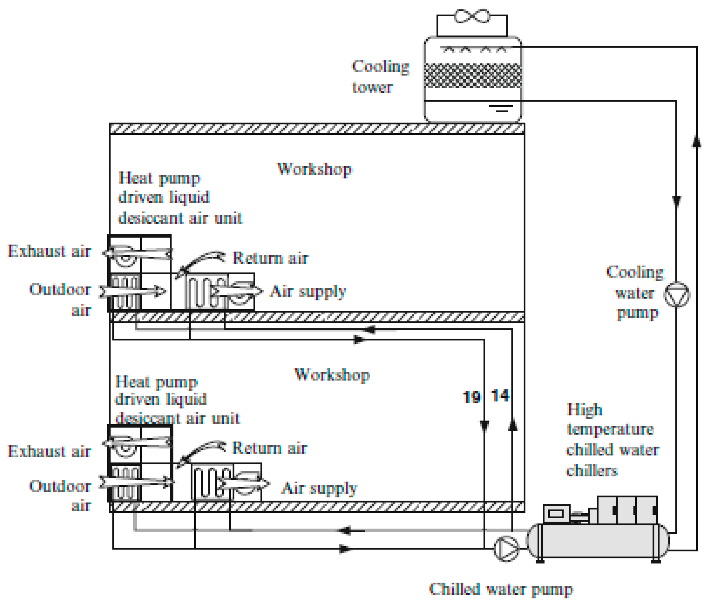
In particularly hot and humid climatic conditions, the TCF technology is not able to deal with both the sensible and latent load as described in Use Case 4. Under the given conditions, TCF technology is integrated with an evaporative cooler or combined with an electrically-driven vapour compression air-conditioning system. The integration of TCF technology with cooling technologies allows to efficiently condition the air, allowing the TCF to deal with latent loads while cooling systems are reducing the sensible loads. In the reference use case of TCF technology replacement for space cooling and air dehumidification [22], an industrial factory for banknote printing located in Beijing with an air-conditioning area of 10,000 m2 was considered. The required indoor conditions for the factory are 24 ± 2 °C and 55 ± 5% RH. The original air-conditioning system of the workshop was composed by AHUs and the dehumidification in the building is obtained by the use of a 7/12 °C chilled water system. After condensation below dew-point to remove water from the air, the air must be reheated to reach the desired indoor conditions. Under Beijing’s climatic conditions, the conventional air-conditioning system is unable to efficiently treat the process air, resulting in an indoor temperature of about 21.5–25.5 °C with a 46–58% RH, missing the required parameters for indoor air. Therefore, the replacement with TCF technology for humidity and temperature control was evaluated.
One of the main advantages resulting from the separate dealing of sensible and latent loads is the opportunity to increase the temperature of the chilled water system because this has to deal only with the latent loads, i.e., the system does not require any more overcooling below the dew-point and reheating. The use of a high temperature cooling water system (14/19 °C) could result in different benefits for the air-conditioning system, such as COP increase, reduction of the cooling system sizing, etc. [23]. The TCF technology replacement for the considered banknote printing workshop is shown in Figure 27.
The energy consumption analysis for the original air-conditioning and TCF system in the considered banknote printing workshop is shown in Table 1.
As reported in Table 1, the annual operating economic savings (summer operation) resulting from TCF technology replacement in the considered banknote printing use case are estimated to be around 118,490 €. For the investment costs, the ability of the TCF technology to separately deal with temperature and humidity improves the efficiency of the air-conditioning process under the considered climatic conditions, allowing to significantly reduce the cooling capacity of the chiller, which only has to deal with sensible loads. This significantly reduces the cost of the chiller between the conventional technology (1574 kW, estimated cost 440,000 €) and TCF replacement (837 kW, estimated cost 235,000 €) [14]. Assuming the cost of the TCF system is able to ensure the needed humidity removal in the banknote printing workshop to be around 145,000 € [13], the total investment cost of the TCF replacement technology is lower than the investment of the conventional system. The inefficiency of conventional electrically-driven vapour compression technology to treat the air at high temperature and humidity in Beijing ambient conditions in summer significantly eases the economics of the TCF technology. Therefore, the climatic conditions are one of the most important parameters for the estimation of the feasibility of TCF technology replacement, particularly for use cases where the TCF technology is used to cool and dehumidify the air. Moreover, a higher air quality in industrial factories results in an increased worker productivity. This factor should also somewhat be accounted to fully evaluate the economic savings resulting from TCF technology employment.

4.6. Drying

In conclusion, TCF technology could significantly improve the economic performance of an industrial drying system. Different sectors could benefit from the TCF technology employment, such as laundry drying, wood drying, biomass drying, paper drying and pharmaceutical [24] and high-tech products, such as semiconductor devices [25]. For the economic savings evaluation, the industrial laundry dryer in Figure 28 is considered.
In the considered use case, the gas heater is used to charge the dryer to remove water out of wet textiles. Therefore, the gas heater and laundry driers are responsible for a high energy consumption in the conventional drying system. The employment of a TCF drying process could significantly reduce the fuel consumption while recovering and exploiting the heat released by the TCF absorption process. The gas heating consumption for the considered TCF dryer is estimated to be around 13 kW, needed to recover thermal losses in the drying chambers. It has been estimated that the primary energy consumption for heating in the industrial laundry dryer shown in Figure 4 is reduced from original 788.4 MWh/y to 113.88 MWh/y, resulting in a reduction of total primary energy consumption by 85%. Assuming a gas price of 0.09 €/kWh, an estimated cost of the desiccant of 0.025 €/kWh and industrial dryer working all year-round [21], the operational cost of the conventional dryer is 70,956 €/y, while the TCF technology is responsible for an annual cost of 13,096 €. The yearly economic savings with a hybrid district network are 57,859.8 €. For the investment cost, the cost of a 90 kW gas heater is estimated to be around 4000 € [15], while the cost of the TCF drying technology is 60,600 €, due to the 600 € of a 13 kW gas heater [15] and the estimated cost of 60,000 € of a 14,760 m3/h TCF absorber system [13,21]. The payback period is about one year (0.98 years).
The considered use cases have shown the economic opportunity to replace conventional technologies with TCF technology for different applications. The payback periods are summarised and displayed in Figure 29. As reported in the figure, the surgery room (0.34 years) and banknote printing workshop (lower investment cost) present the lower payback periods under the given conditions. However, the performed economic analysis considered very humid climatic conditions, which highly eases the economic efficiency of the TCF technology. Ambient air with a lower content of moisture decreases the economic efficiency of the process for cooling and dehumidification. Indoor pools and industrial dryers could also save significant amounts of money with TCF technology replacement, showing a return on the economic investment lower than one year. To conclude, all the considered use cases show a payback period lower than the expected technology lifespan (20 years), making the TCF hybrid district network a very promising energy-efficient, sustainable and economic technology.

5. Simulation of the Use Case of Space Heating and Heat Recovery

This section describes a physical simulation approach for the thermo-chemical technology that has been developed to prove the detailed applicability of the thermo-chemical technology in specific situations with full-detail conditions. The modelling approach is demonstrated in this section by Use Case 3 (building space heating). This case utilizes the absorption process to heat the air that can directly serve to heat the building by means of an air-based system.

5.1. Simulation Objectives and Approach for a Test Case

Absorption and desorption processes work with relative low temperature differences. This requires a dynamic simulation approach to check if the services, especially space heating and cooling, can be provided. Therefore, the aim of the development of a simulation approach is to test if the absorption process can provide the required temperature and heating power at different airflows and TCF flows for a representative test case. The simulation model will be validated with measurements from a test bench and from demonstrators in the H-DisNet project [2].
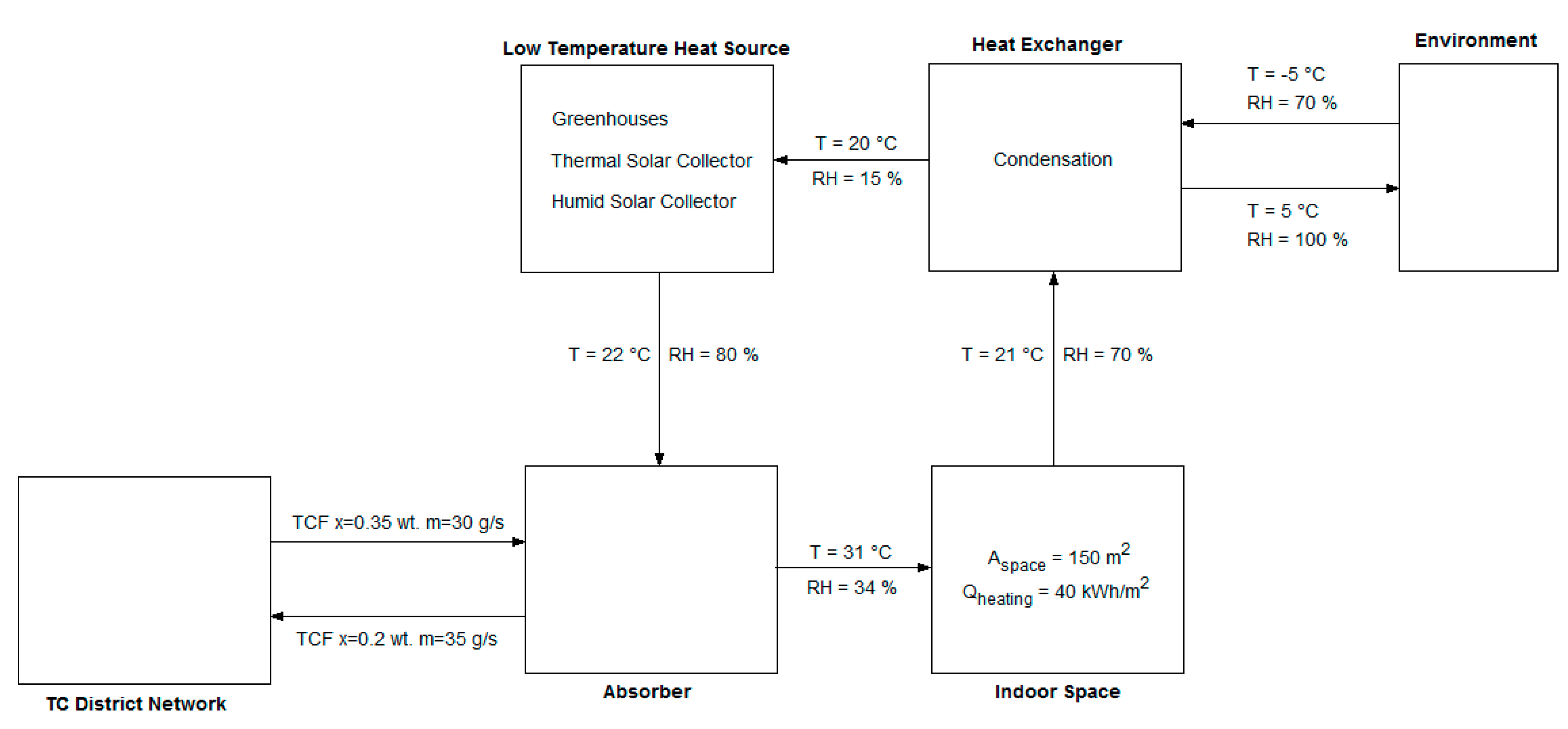
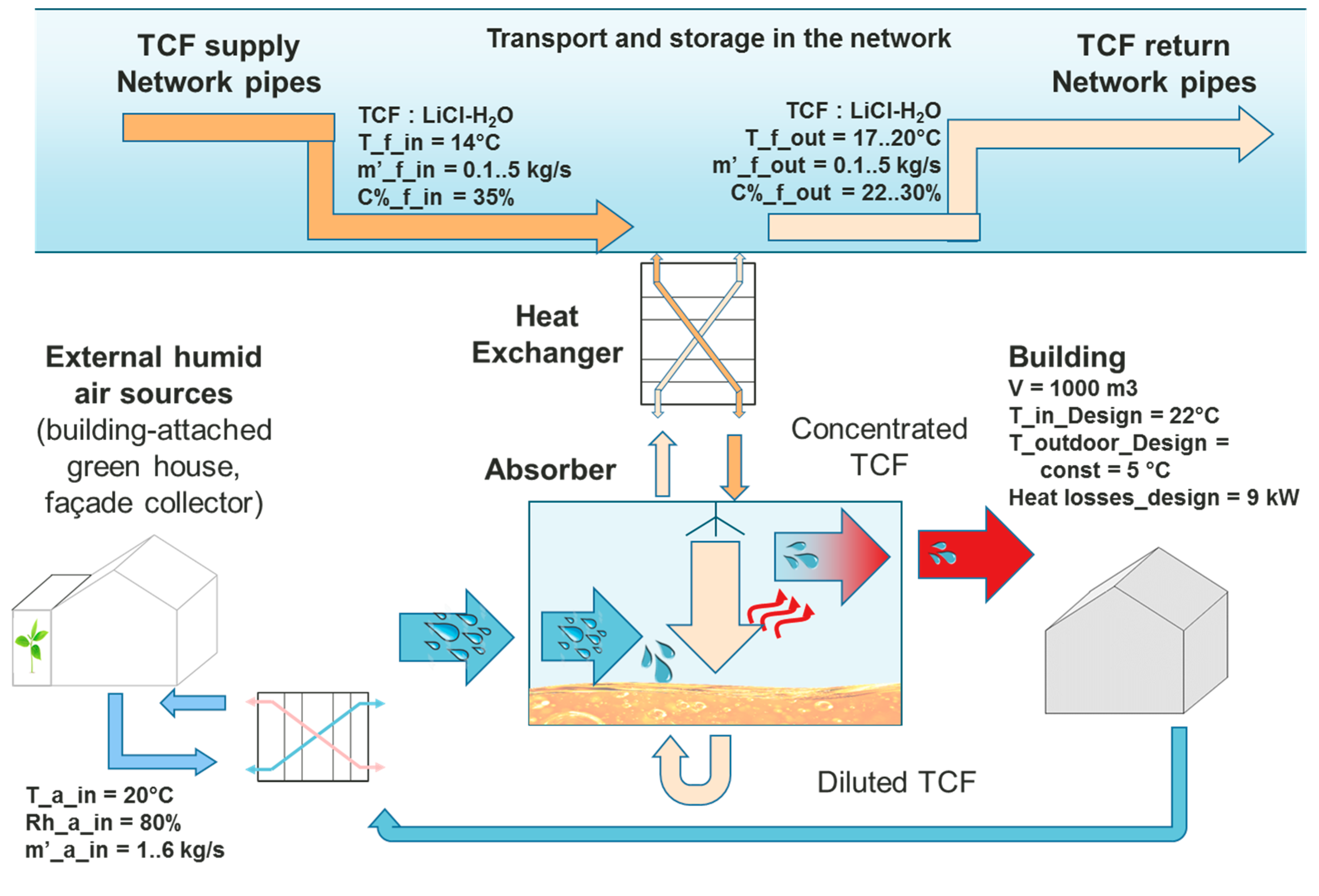
Figure 30 shows the model flow scheme of a building heating system with heat recovery based on the absorption process. The TCF (dark orange arrows) comes from the network with higher concentration to enter the building through a heat exchanger, where the heat transfer takes place between the supply and return pipes to transfer sensible heat to the supply TCF and, thus, to avoid thermal losses to the cold network. Then it goes to the absorber to take up humidity from the air (blue arrow). As a result, heat is released amounting to 680 kWh/t of absorbed water. By this energy, the air is heated up, dried and purified to go directly to the building via the ventilation system to heat the building (red arrow). The outgoing warm air from the building is humidified by an external very low temperature heat source (e.g., a greenhouse at 15–20 °C). A heat exchanger may be used to reduce the sensible heat losses in the greenhouse. Finally, the TCF that is diluted by the absorption process returns through the heat exchanger to the return network pipes to be re-concentrated in the regeneration at the supply side of the district network.
In the current state of the simulation model, TCF is provided from the network with constant concentration, as it is shown in Figure 30, whereas the humid air is provided from an external humidity source with constant relative humidity and temperature. Both TCF and humid air go to the absorber model with specific flows that are varied for test purposes to understand the performance of the system.

5.2. Modelica Model and the Boundary Conditions

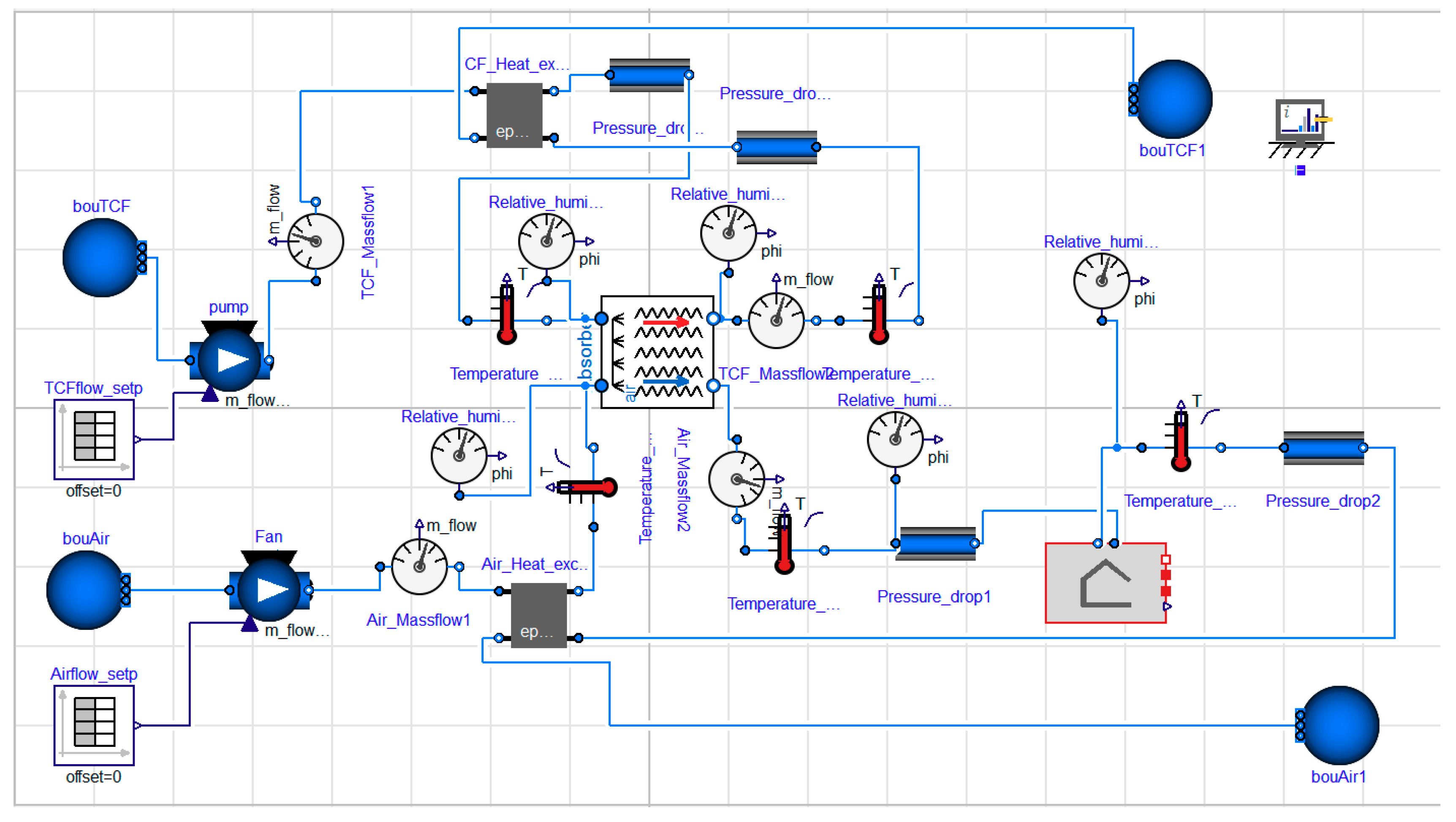
The simulation model is created in the Modelica environment (Figure 31). It is compiled and simulated with Dymola 2017 by using the Modelica standard library [26], IDEAS library [25] and other developed models (such as the absorber model, medium model and building model). The simulation model is dynamic and consists of the components shown in Table 2:
The main objective of this simulation is to test the absorption process in a building for space heating. Therefore, many boundary conditions were assumed to be constant to clearly observe the absorption behaviour. The models’ conditions are listed as shown in Table 3.
External humid air source model: There are many humid air sources, such as greenhouses and swimming pools. To test the absorption process, a constant air temperature and absolute air humidity were assumed to have these values, Table 4.
TCF supply source model: The TCF is LiCl-H2O, as well as the humid air source, a constant TCF temperature and concentration were assumed, as shown in Table 5.
Absorber model: The volume of the absorber is 1 m3, the specific interaction area is 100%, the interaction nodes are two nodes for air and two nodes for TCF and the dehumidification process is adiabatic.

5.3. Test Plan and Simulation Results

The key variables that effect on the outcomes of the absorption process are the airflow and TCF flow, as well as the ratio between them. Therefore, Table 6 was set up to examine combinations of airflow values with corresponding TCF flows. As a result, the outgoing heat of the absorber is varying based on the combinations of the two flows.
TCFflow = ( n i )   ×   airflow 6
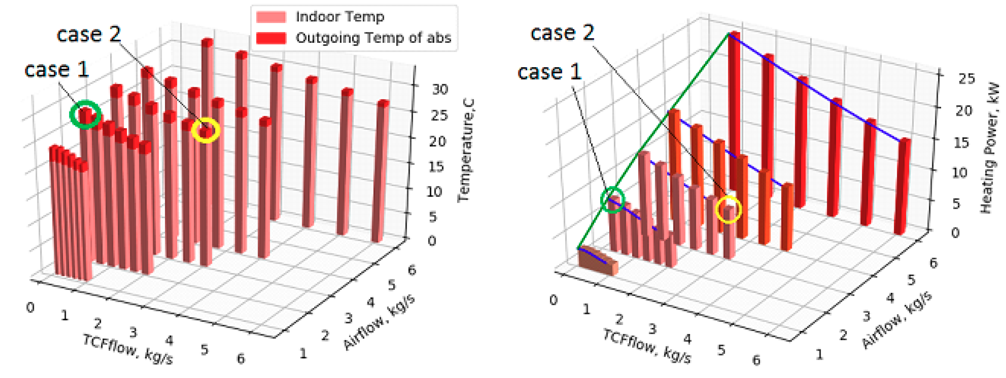
The results of the simulation illustrate the potential of the absorption process to produce heat for the building. Figure 32, left, shows the outgoing temperature of the absorber (dark red) and the building indoor temperature (light red) versus different airflows and different TCF flows against every airflow.
As expected, the outgoing temperature of the absorber increases with higher airflows within a specific range. In contrast, the outgoing temperature increases with lower TCF flows. For instance, the highest outgoing temperature is 32.9 °C, which corresponds to the highest airflow of 6 kg/s and a TCF flow of 1 kg/s, while the lowest outgoing temperature corresponds with the same airflow of 6 kg/s but the highest TCF flow of 6 kg/s is 27.5 °C. In comparison, the outgoing temperature with the lower TCF flow of 1 kg/s and the lowest airflow of 1 kg/s is 22.7 °C.
Similarly, Figure 32, right, shows the heating power versus the airflows and TCF flows, where the heating power increases with higher airflows and lower TCF flows. Therefore, in this simulation case under the constant outdoor temperature conditions, which is 5 °C, the required heat for the building is 9 kW, which corresponds to an airflow of 2 kg/s and a TCF flow of 0.33 kg/s (further details to follow).
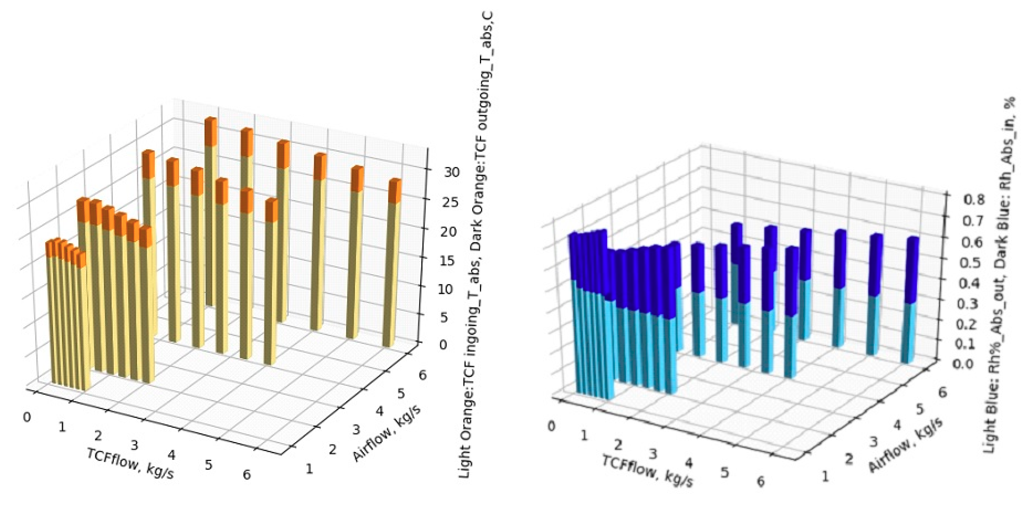
The TCF surface is in direct contact with the air. As a result, besides the humidity exchange, the heat is also exchanged by conductive heat transfer. Therefore, both the temperature of air and the TCF are approximately equal. Thus, as it is shown in Figure 33, left, the TCF temperature behaves similarly to the air temperature with respect to the airflow and TCF flow.
Simultaneously, the relative humidity decreases after the absorption process. Hence, the humidity in the air is absorbed by the TCF to release the heat as a result. The amount of the absorbed humidity depends on the airflow, TCF flow and the ratio between them, as shown in Figure 33, right.
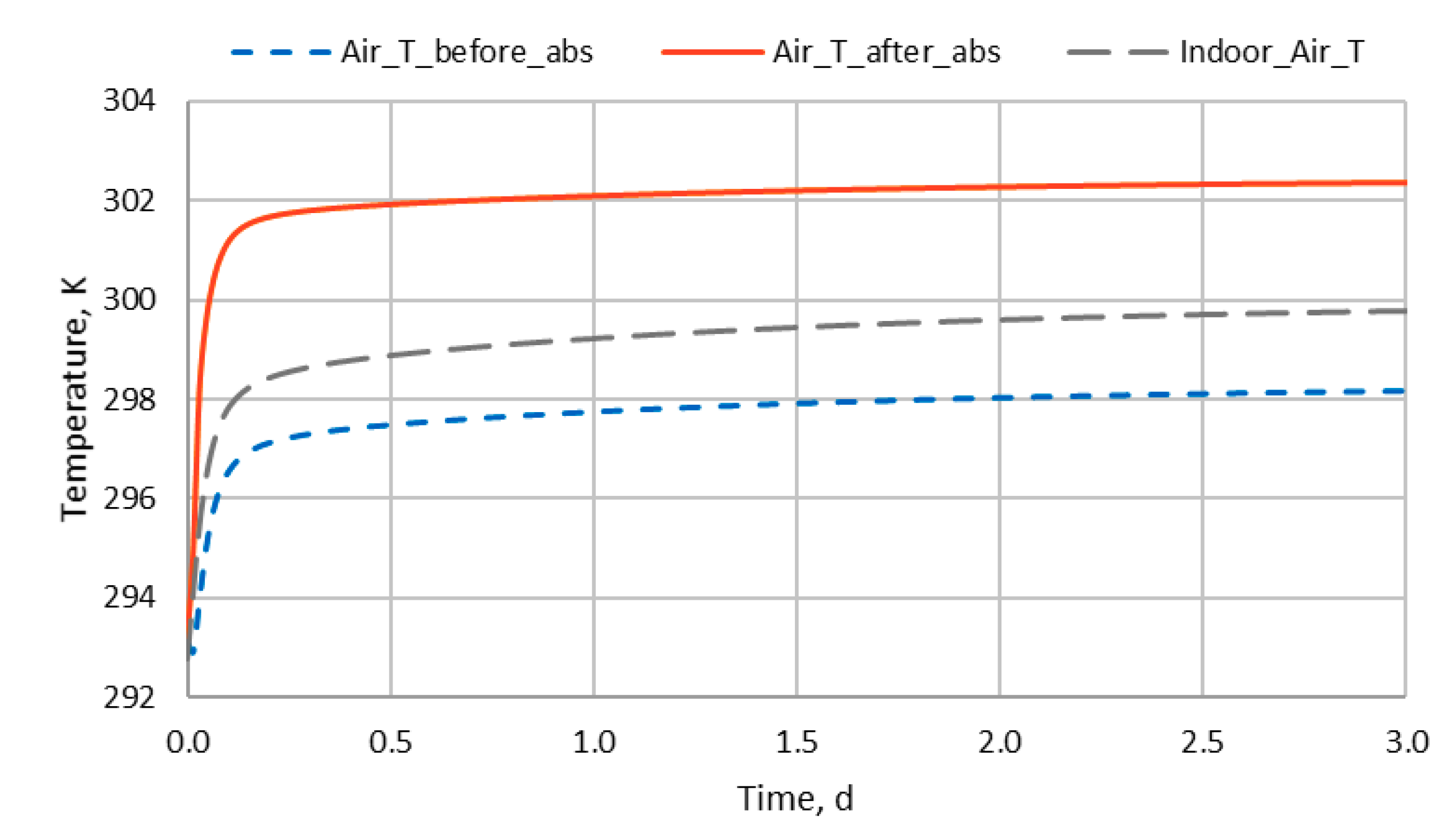
Figure 34 presents the simulation results of the temperature before and after the absorber and the indoor temperature of a building with one specific airflow and TCF flow. The results show that the absorption process needs some time to become stable. As expected, the temperature after the absorption process increases around 4 K and, as a result, heat energy flows from the absorber to the building and the indoor temperature increases. The ingoing airflow is 2 kg/s and the ingoing TCF flow is 0.33 kg/s.
Table 7 shows a snapshot of the simulation results at 1.5 days for the temperatures and the supply heating power, together with the airflow and TCF flow. As a result of the absorption process in the absorber with 2 kg/s airflow and 0.33 kg/s TCF flow, the temperature increases 4.2 K and the provided heating power to the building is 9 kW, which raises the indoor temperature to 299.2 K.
For better performance of the absorber, the ratio between the airflow range 1–6 kg/s and TCF flow range 0.1–6 kg/s should be tuned to have a higher heat amount with lower pumping power. For example, Table 8 and Figure 32 show two cases of pumping and heating power of the absorber with low and high airflows and TCF flows. In Case 1, the performance is better. The pumping power is lower than Case 2, while the heating power is only slightly lower. The ratio of pumping power to useful power is 0.072 instead of 0.118.

5.4. Discussion of Simulation Results

The simulation results show that the absorption process produces heat for the space heating service. The amount of this heat depends on the airflow and TCF flow and the ratio between them, which can be set based on the model conditions, including the size of the absorber, specific interaction area and TCF type. Thus, the temperature lift of the absorption process is between 2.2 °C and 4.3 °C within the tested flow ratios, which produces a heat between 2 and 25 kW. However, these values are associated to the size of the absorber and TCF. In other words, the absorber with a volume of 1 m3 can provide heat to a building with required heat between 2 and 25 kW.
Moreover, in this simulation case, there are some limitations or boundaries that should be taken into consideration to guarantee obtaining better performance. Hence, the ratio between the airflow and TCF flow is an important factor for the efficiency of the system. It is interesting to observe that, in this case, a relatively low TCF flow of 0.33 kg/s (Case 1) has nearly the same performance as a ten times higher TCF flow at a mass flow ratio of 3 kg/s (Case 2). Since the aim of this simulation is to define the capability of this absorber, no control strategy has been applied to control the incoming heat amount into the heated space. However, control will improve the efficiency of the system further.
The future work of this simulation regarding Use Case 3 (building space heating) is simulating with full dynamic conditions, including the heating space, ingoing air and ingoing TCF. Moreover, a control strategy to serve in this use case will be developed to undertake the required heat amount from the absorber. Similar simulation approaches will be developed for the other use cases. Furthermore, the simulation models of multi-node TC networks components will be calibrated with experimental results from laboratory to adapt the thermo-chemical components to the real performance. Subsequently, machine learning will be used to model the absorber, heat exchanger and greenhouse as surrogate models at the network level, which will accelerate the simulation time to examine cases with hundreds or thousands of nodes in thermo-chemical networks.

6. Conclusions

The diversity of use cases, together with their high economic benefit shown by short payback periods, indicate the potential of a multifunctional thermo-chemical district network. Considering the potential to replace primary energy demand, the economic benefit and the technological feasibility, the following use cases are of high interest:
  • All humidity-related applications (UC 1–humidity removal, UC 2–humidity control and UC 5–industrial drying) are easy to implement from a technological point of view and cause high energy demand with conventional technology. This also makes them economically beneficial. Thus, they are very interesting candidates. Especially, for industrial drying, a relatively high volume is known which makes the application of the technology interesting.
  • The use case space heating (UC 3) has the highest potential in terms of primary energy consumption. However, this use case is also the most complex one from a technological point of view. As a consequence, the case has a comparable long payback period. However, in terms of reducing primary energy consumption, it has high potential. Simulation results of space heating have shown that the process is able to produce the required heat under the condition of exact control of the airflows and TCF flows because the ratio between them is crucial for power and supply temperature.
  • For space cooling (UC 4), the combination with conventional compression cold is promising, as this removes latent humidity-related loads from the chiller and allows a smaller dimensioning of the device operating at higher temperature with better COP. In that situation, a lower investment costs for the combined system than for the conventional system are expected to make it economically appealing.
  • Furthermore, the technology with its loss-less storage and transport allows to exploit very low-temperature heat sources (30–60 °C) distant to the demand side. Driving the processes with this potential leads to a significant increase of the primary energy efficiency. Moreover, in a network, new capacities of storage and load balancing become available. The technology does not only allow bridging larger distances but also longer times than conventional thermal district network technology.
In summary, the examination of the use cases of thermo-chemical processes and their integration in networks demonstrates the potential and the flexibility of the technology. In the future, more detailed research on the dynamic behaviour by lab experiments and simulations, as well as implementation in demonstrators, will make the technology in the H-DisNet project ready for application.

Acknowledgments

The presented results origin from the project H-DisNet funded by the European Commission in the Horizon 2020 program under grant No. 695780. The structure of the use cases with their requirements has partially been developed in general assemblies with contributions of the project partners.

Author Contributions

M.B., P.G., R.B. and M.P. developed the schemes and use cases described in Section 3 with input from the whole consortium. A.G., A.S. and A.P.R. performed the economic analysis shown in Section 4. M.D. developed the simulation model with advice of P.G., M.B., M.D. and A.G. wrote the paper. The other authors critically read the paper.

Conflicts of Interest

The authors declare no conflict of interest. The founding sponsors had no role in the design of the study; in the collection, analyses, or interpretation of data; in the writing of the manuscript; or in the decision to publish the results.

References

  1. Enova. Utnyttelse av Spillvarme fra Norsk Industri-en Potensialstudie; Enova: Oslo, Norway, 2009. [Google Scholar]
  2. H-DisNet–Intelligent Hybrid Thermo-Chemical District Networks. Available online: https://www.h-disnet.eu/ (accessed on 2 November 2017).
  3. Object Management Group Systems Modeling Language, Specifications Version 1.5. Available online: http://www.omg.org/spec/SysML/1.5/ (accessed on 16 June 2017).
  4. Brown, J.P.; Rose, W.B. Development of Humidity Recommendations in Museums and Moisture Control in Buildings. Available online: http://cool.conservation-us.org/byauth/brownjp/humidity1997.html (accessed on 20 October 2017).
  5. Mortimer, D. Controlling humidity for healthier hospital. Health Estate 2015, 69, 39–43. [Google Scholar] [PubMed]
  6. Persson, U.; Möller, B.; Werner, S. Heat Roadmap Europe: Identifying strategic heat synergy regions. Energy Policy 2014, 74, 663–681. [Google Scholar] [CrossRef]
  7. Eurostat, Electricity Generated from Renewable Energy Sources, EU-28, 2005–2015. Available online: http://ec.europa.eu/eurostat/statistics-explained/index.php/Renewable_energy_statistics,EU-28,2005-2015_YB17-de.png (accessed on 22 February 2018).
  8. Mujumdar, A. Handbook of Industrial Drying; CRC Press: Boca Raton, FL, USA, 2015; ISBN 978-1-4665-9665-8. [Google Scholar]
  9. EU RHC Platform. 2020–2030–2050 Common Vision for the Renewable Heating & Cooling sector in Europe; European Technology Platform on Renewable Heating and Cooling: Brussels, Belgium, 2011. [Google Scholar]
  10. CEPI. Key Statistics 2015 CEPI—Confederation of European Paper Industries. Available online: http://www.cepi.org/statistics/keystatistics2015 (accessed on 23 October 2017).
  11. Laurijssen, J.; Faaij, A.; Worrell, E. Benchmarking energy use in the paper industry: A benchmarking study on process unit level. Energy Effic. 2013, 6, 49–63. [Google Scholar] [CrossRef]
  12. Liu, X.; Yang, Z.; Gluesenkamp, K.R.; Momen, A.M. A Technical and Economic Analysis of an Innovative Two-Step Absorption System for Utilizing Low-Temperature Geothermal Resources to Condition Commercial Buildings; PROCEEDINGS, 41st Workshop on Geothermal Reservoir Engineering; Stanford University: Stanford, CA, USA, 22–24 February 2016. [Google Scholar]
  13. Sustainable Design & Consulting LLC; Hawaii Natural Energy Institute. Application of Innovative Desiccant Dehumidification Technologies in Hawaii-Task 7. Asia Pacific Research Initiative for Sustainable Energy Systems 2011 (APRISES11); Grant Award Number N0014-12-1-0496; Office of Naval Research: Manao, HI, USA, 15 June 2017. [Google Scholar]
  14. Lu, Y.; Roskilly, A.P.; Ma, C. A techno-economic case study using heat driven absorption refrigeration technology in UK industry. Energy Procedia 2017, 123, 173–179. [Google Scholar] [CrossRef]
  15. Combi-Boiler Prices. Available online: http://www.boilersprices.co.uk/combi-boilers-prices/ (accessed on 18 January 2018).
  16. AIL Research. Pools Application. Available online: http://ailr.com/applications/pools/ (accessed on 17 October 2017).
  17. Advantix Systems. Hotel Case Study. Available online: http://www.evergreen-environmental.com/AC/Finalweb-Hotel.pdf (accessed on 17 October 2017).
  18. Advantix Systems. Surgery Room Case Study. Available online: http://www.addisonsmith.net/sites/default/files/carrollton-surgery-center-casestudy.pdf (accessed on 17 October 2017).
  19. Fu, H.X.; Liu, X.H. Review of the impact of liquid desiccant dehumidification on indoor air quality. Build. Environ. 2017, 116, 158–172. [Google Scholar] [CrossRef]
  20. Geyer, P.; Buchholz, M.; Buchholz, R.; Provost, M. Hybrid thermo-chemical district networks–Principles and technology. Appl. Energy 2017, 186, 480–491. [Google Scholar] [CrossRef]
  21. Giampieri, A.; Buchholz, M.; Geyer, P.; Buchholz, R.; Engel, C.; Royapoor, M.; Smallbone, A.; Roskilly, A.P. Application Cases and Economic Benefits of Thermo-Chemical Networks. In Proceedings of the 4th Sustainable Thermal Energy Management International Conference (SusTEM2017), Alkmaar, The Netherlands, 28 June 2017. [Google Scholar]
  22. Liu, X.; Jiang, Y.; Zhang, T. Temperature and Humidity Independent Control (THIC) of Air-Conditioning System; Springer: Heidelberg, Germany, 2013. [Google Scholar]
  23. Wulfinghoff, D.R. Energy Efficiency Manual; Energy Institute Press: Wheaton, MD, USA, 1999. [Google Scholar]
  24. Advantix Systems. Pharmaceutical Case Study. Available online: http://advantixsystems.cn/wdf/pdf/Case_Study_Pharmaceutical.pdf (accessed on 17 October 2017).
  25. Baetens, R.; De Coninck, R.; Jorissen, F.; Picard, D.; Helsen, L.; Saelens, D. Openideas-an Open Framework for Integrated District Energy Simulations. In Proceedings of the International Conference of the International Buildings Performance Simulation Association, Hyderabad, India, 7–9 December 2015. [Google Scholar]
  26. Modelica and the Modelica Association—Modelica Association. Available online: https://modelica.org/ (accessed on 6 November 2017).
  27. Fürst, Y.; Kriegel, M. Adiabatic Absorber Model for the Liquid Desiccant Distribution Network at the Technology Park Berlin Adlershof Using Modelica. In Proceedings of the BauSIM Conference, Dresden, Germany, 14–16 September 2016; Available online: https://www.researchgate.net/publication/312084480 (accessed on 22 February 2018).
  28. Pátek, J.; Klomfar, J. Thermodynamic properties of the LiCl–H2O system at vapor–liquid equilibrium from 273K to 400K. Int. J. Refrig. 2008, 31, 287–303. [Google Scholar] [CrossRef]
Figure 1. Temperature levels and utilization of excess heat in industry in Norway (data source: Enova, 2009).
Sustainability 10 00599 g001
Figure 2. The basic processes of thermo-chemical systems absorption and desorption.
Sustainability 10 00599 g002
Figure 3. Basic scheme of the drying process.
Sustainability 10 00599 g003
Figure 4. Basic scheme of the heating and heat recovery process.
Sustainability 10 00599 g004
Figure 5. Basic scheme of the cooling process.
Sustainability 10 00599 g005
Figure 6. Regeneration of the TCF by low-grade excess heat.
Sustainability 10 00599 g006
Figure 7. Desorption and absorption processes with the TCF transport in between forming the thermo-chemical network.
Sustainability 10 00599 g007
Figure 8. Example for an absorber and desorber design with an internal TCF heater, vertical textile cylinders and overflow distribution allowing for low flow velocity of the TCF with a long contact time to air (Source: Watergy GmbH).
Sustainability 10 00599 g008
Figure 9. The thermo-chemical network allows the supply of fluid by a demand-side storage (orange) and dehumidification service within a closed air cycle. Compared to heat recovery ventilation, the supply air from the absorber (blue) is always warmer than the exhaust air from the enclosure. As sensible heat from air and latent heat conversion is transferred to the TCF. There is also the option of heat accumulation and retention of heat release (e.g., collection of heat from internal sources during daytime and use for room pre-heating in the morning). The internal air cycle allows to prevent exceeding humidity limitations and, as providing direct contact between TCF and air, also removes organic particles from the air. This allows to significantly reduce ventilation rates and, by this, also a large part of the energy losses.
Sustainability 10 00599 g009
Figure 10. In heat recovery mode, humidity from the supply air process and internal humidity sources are captured by a second absorber allowing to convert it to sensible heat. The heat is transferred to the TCF and is pumped to the supply air side, where it is used to supply air pre-heating. In contact with ambient air, it strongly cools down and is pumped back to the exhaust air channel.
Sustainability 10 00599 g010
Figure 11. Humidity removal and heat recovery ventilation in buildings use case.
Sustainability 10 00599 g011
Figure 12. Set point humidity control in buildings use case.
Sustainability 10 00599 g012
Figure 13. Use case of space heating with heat recovery.
Sustainability 10 00599 g013
Figure 14. In an internal heating cycle, the absorber provides a warm TCF, heated by an additional low temperature heating device (red) and allows supply of heat and humidity in direct contact to the air in the room. Once, the equilibrium humidity of the salt is reached, additional humidity from internal sources are captured and re-transferred to sensible heat. In ventilation mode, the principle works like in Figure 2.
Sustainability 10 00599 g014
Figure 15. During circulation mode, the second absorber can be used to capture low-temperature heat and latent heat from the ambient air. The circulation mode with TCF allows for reduction of internally-released humidity and organic air compounds, thus, significantly reducing the need for air exchange and related energy consumption.
Sustainability 10 00599 g015
Figure 16. By integrating a humid air solar collector, e.g., a façade greenhouse, the temperature and humidity rate supplying the heat pump is significantly increased. Greenhouse air can be used if its enthalpy rate is higher than ambient air. Moreover, a part of the façade energy losses of the building are captured by the greenhouse. During phases of sunshine, the higher efficiency of the heat pump, caused by higher feed temperatures can be used to feed a thermal storage (orange box) so that the heat pump can be switched off during the night or during periods without sunshine or expensive electricity.
Sustainability 10 00599 g016
Figure 17. In ventilation mode, the heat pump can be additionally fed by exhaust air as part of the heat recovery. At least a part of the energy provided for air humidification in the supply air can be recovered.
Sustainability 10 00599 g017
Figure 18. Cooling use case.
Sustainability 10 00599 g018
Figure 19. A heat pump providing additional cooling for areas with higher temperatures and/or humidity loads. The excess heat of the heat pump is not cooled by the evaporation process. This runs at a range of 15–25° and by this it is less vulnerable to legionella growth. Moreover, the heat is stored in the thermal storage (blue box). Heat from the supply air uptake and dehumidification, as well as from the heat pump is stored and can be used during night for TCF regeneration. In this way, a system like this can switch between supply- and demand-side functions in a hybrid network.
Sustainability 10 00599 g019
Figure 20. A basic cooling function can be provided by evaporation of water in the exhaust air channel. Cool water (blue cycle) helps to remove heat in the TCF (black cycle). The cold TCF can provide supply air dehumidification and cooling in one step. During night, this function can be used to fill a cool storage (blue) that can be used during the phase of highest cooling demand during daytime. The TCF allows dehumidification of air without reaching the dew point. This allows running the air conditioning at significantly higher cooling temperatures (~18 °C instead of ~8 °C).
Sustainability 10 00599 g020
Figure 21. Industrial drying use case.
Sustainability 10 00599 g021
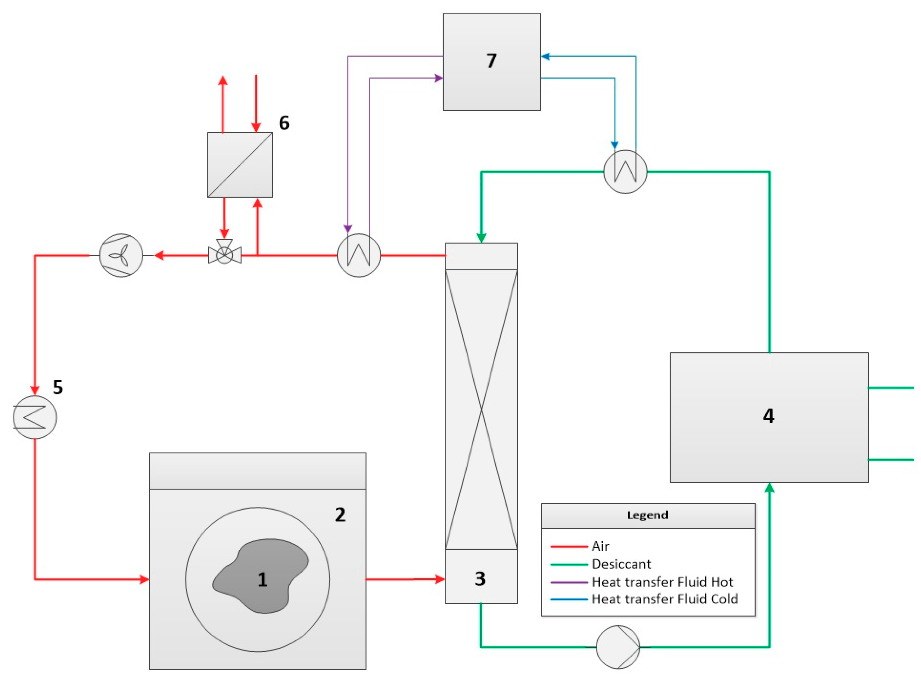
Figure 22. Absorber box (3) allows recovering sensible heat from humid air in the exhaust air of the drying chamber (2) with the help of a liquid TCF from local storage (4) or from the network directly. In this way, the dry/hot air produced can be redirected back to the chamber (2). Fresh air supply is only needed to remove particles or exhaust gases coming from the drying material (1) or from the heating process (5). A further heat recovery unit (6) can be used for additional energy efficiency in case of economic justification.
Sustainability 10 00599 g022
Figure 23. The absorption process recovers heat from air. If needed, the heat released can also be captured from the heated TCF to support the heating cycle of the drying unit. This might be used in a conductive process, where heat is not provided to the air but to the drying material (1) through a conductive heater (2).
Sustainability 10 00599 g023
Figure 24. A heat pump-driven drying process can be combined with the absorption process. In this way, the set point humidity and temperature of the air can be controlled separately.
Sustainability 10 00599 g024
Figure 25. Use case of a surgery room air-conditioning with TCF technology [18], modified.
Sustainability 10 00599 g025
Figure 26. Use case of space heating with TCF technology [20].
Sustainability 10 00599 g026
Figure 27. Use case of temperature and humidity control with TCF technology in a banknote printing workshop [22].
Sustainability 10 00599 g027
Figure 28. Comparison between conventional and TCF-based industrial laundry dryers [21].
Sustainability 10 00599 g028
Figure 29. Payback period with TCF technology replacement.
Sustainability 10 00599 g029
Figure 30. Flowcharts of the heating and heating recovery, including the absorption process.
Sustainability 10 00599 g030
Figure 31. Modelica/(Dymola) model for the building, space heating Case 3.
Sustainability 10 00599 g031
Figure 32. (Left) Indoor temperature and outgoing temperature of the absorber versus airflows and TCF flows. (Right) Heating power versus airflows and TCF flows.
Sustainability 10 00599 g032
Figure 33. (Left) TCF ingoing temperature and outgoing temperature of the absorber versus airflows and TCF flows. (Right) Relative humidity of the ingoing flow and outgoing flow versus airflows and TCF flows.
Sustainability 10 00599 g033
Figure 34. Ingoing temperature before the absorber (orange solid line), outgoing temperature after the absorber (blue dash line) and indoor temperature of the building (grey long dashed line).
Sustainability 10 00599 g034
Table 1. Comparison of energy consumption and economic savings of conventional and TCF technology for air-conditioning in a banknote printing workshop [22].
Original SystemTCF + High Temperature Chiller
DevicesChillerReheatTCF systemChiller
Rated cooling capacity1574 kW-206 kW837 kW
Rated power consumption463 kW-56 kW164 kW
Rated reheat consumption-532 kW--
Power consumption (summer)1167 MWh 554 MWh
Gas consumption (summer)230,003 m3 -
Operating cost (summer)1,370,000 CNY 440,000 CNY
174,536.15 € *56,055.4 € *
* 1 CNY = 0.127413 €.
Table 2. Modelica model components.
ModelsDescription
Fan/pump modelDescribed by mass-flow and pressure [26].
Absorber modelA finite volume model, with a cross-flow configuration, as developed by Fürst [27]; the interaction nodes are two nodes for air, two nodes for TCF. The dehumidification process is adiabatic, i.e., no heat is exchanged with the environment. The interface of the humid air and TCF are in equilibrium with respect to temperature and humidity.
Medium modelLiCl-H2O model is developed by Fürst [27] based on the thermodynamic properties and its equations of state are based on the paper of Pàtek and Klomfar [28].
Building modelThe model is based on the Structure model of the IDEAS library [25].
Heat exchanger modelHeat exchanger of TCF circuit is TCF–TCF, heat exchanger of the air circuit is air–air, from the IDEAS library [25].
Pressure drop modelDescribed by mass-flow and pressure, IDEAS library [25].
Constant source modelFor temperature and humidity, IDEAS library [25].
Thermostat model and relative humidity sensor modelTo measure the temperature and relative humidity, IDEAS library [25].
Table 3. Building model conditions.
ParametersValueUnit
U value for outer wall, roof and ground0.30W/m2K
U value for windows1.015W/m2K
The volume of the building1000m3
Indoor design temperature22°C
Outdoor design temperature5°C
Maximum heat losses9kW
Outdoor temperature was assumed to be constant to have static building heat losses5°C
Table 4. External humid air source conditions.
Parameters ValueUnit
Input temperature 20°C
Relative humidity75%
Absolute humidity11g/kg
Mass flows through the absorber1–6kg/s
Table 5. TCF supply source conditions.
Parameters ValueUnit
Input temperature 14°C
Concentration35%
Mass flows through the absorber1–5kg/s
Table 6. The airflow values with the corresponding TCF flows.
Airflows, kg/sTCF Flows, kg/s
1 × airflow 6 2 × airflow 6 3 × airflow 6 4 × airflow 6 5 × airflow 6 6 × airflow 6
10.170.330.500.670.831
20.330.6711.331.672
332.521.510.5
40.671.3322.673.334
6123456
Table 7. Selected values of the absorption input/output temperatures and the required heating power versus airflow and TCF flow at 1.5 days.
Time, dT before abs, KT after abs, KIndoor T of BuildingAirflow, kg/sTCF flow, kg/sHeating Power, kW
1.5298302.2299.220.339
Table 8. Different cases to show the pumping and heating power of the absorber with different airflows and TCF flows at 1.5 days.
Airflow, kg/sTCF $low, kg/sAirflow, TCF Flow Ratio (kg/kg)Pumping Power, kWHeating Power, kWPower Ratio
Case 120.330.1650.64790.0688
Case 2331 0.9678.20.10631