Numerical Analysis of the Behavior of an IPM Bridge According to Super-Structure and Sub-Structure Properties

1
Kumoh National Institute of Technology, Gumi-si 39177, Korea
2
Research Institute of Korea Expressway Corporation, Hwaseong-si 18489, Korea
*
Author to whom correspondence should be addressed.
Sustainability 2018, 10(3), 833; https://doi.org/10.3390/su10030833
Submission received: 28 January 2018
/
Revised: 9 March 2018
/
Accepted: 14 March 2018
/
Published: 15 March 2018
(This article belongs to the Collection Sustainable Built Environment)
Abstract
:A bridge with an integrated and pile-bent abutment with a mechanically stabilized earth-wall (IPM) was developed by separating earth pressure from the abutment to overcome the problems typically faced by integral abutment bridges. Also, the IPM bridge removes expansion joints and bearing by integrating the super-structure and the abutment and does not need many piles because it separates the earth pressure from backfills. Therefore, it is superior in cost, durability, and maintainability to traditional bridges and is sustainable due to using less material. A numerical analysis was conducted to ascertain the behavior of the IPM bridge according to its super-structural and sub-structural characteristics. Based on the analysis results, the behaviors of the IPM bridge are as follows: The bending moments of the pre-stressed concrete (PSC) girder and the steel-plate girder of the bridge were influenced by the presence of the time-dependent loads. The contraction behavior in the PSC girder is largely due to the time-dependent loads, whereas the expansion behavior in the steel-plate girder is large due to its greater thermal expansion coefficient and temperature range compared with those of the PSC girder. In general, the suggested bridge length limit for PSC girders in both the integral abutment bridge and the IPM bridge is larger than that in a steel bridge. This needs to be reviewed again with consideration of the long-term and seasonal behaviors.
1. Introduction
A typical bridge supports vertical loads and lateral displacements on the super-structure using bearing and expansion joints. Mechanical devices in these joints are subject to damage caused by the thermal expansion and contraction of the bridge structure, and abutment backfill settlement. This means that consistent maintenance and repairs are required during its service life, as otherwise, the bridge superstructure may be damaged.
In Europe and the US, the integral abutment bridge (IAB) was developed and has been widely used to eliminate the use of bearings and expansion joints from the joint bridge. In the IAB, instead of the general reverse T-shaped abutment (T-abutment), the stub abutment is mainly employed because it exhibits integrated behavior through the use of a rigid link with a super-structure and a pile foundation [1]. As the super-structure and the sub-structure of the IAB always exhibit rigid-link integration, the super-structural behavior is closely related to the sub-structure of the bridge, including the pile foundation and the pressure. In particular, the lateral displacement of the super-structure (by thermal expansion, drying shrinkage, creep, and other causes) largely influences bridge behavior [2]. The IAB bridge is advantageous because it integrates super-structure and sub-structure so that it does not fall down during earthquakes. In recent years, research into the application of seismic isolation bearings on the semi-IAB bridge has begun. These seismic isolation bearings have previously been applied to building structures rather than bridges but have also recently been applied to bridges [3,4].
The lateral displacement of the IAB super-structure leads to a passive earth pressure on the stub abutment. In this regard, Civjan, et al. [5], Nam and Park [6], and Park and Nam [7] defined the passive soil-pressure changes by conducting long-term field measurements on IABs. Ahn, et al. [8] analytically defined the passive earth pressure using long-term thermal expansion of the pre-stressed concrete (PSC) girder in the IAB. In addition, the lateral displacement of the super-structure is resisted by the pile foundation on the stub abutment, for which theoretical, numerical, analytic, and experimental studies have been conducted by some researchers [9,10,11,12,13,14,15,16,17,18,19,20,21,22,23,24,25,26,27,28,29]. According to these studies, the IAB is governed by the maximum bending moment that acts on the pile-head and is generated by the lateral displacement of the girder. Such a lateral displacement is affected by the thermal expansion of the girder, which is further influenced by creep (CR) and shrinkage (SH) [30,31,32]. Therefore, the span of an IAB is limited so as not to exceed the maximum pile-head bending moment capacity when resisting bending that is caused by excessive lateral displacement of the girder [9,10,33,34]. To reduce this limitation, studies involving the hinge bar and elastic pad installed in the IAB abutment for the purpose of reducing the maximum pile-head bending moment are ongoing [9,35,36,37].
The various advantages of the IAB, as well as its weaknesses, result from its integration-type condition. The IAB abutment uses lateral earth pressure on the front fill to resist the lateral displacement. However, this fill reduces the under-bridge space thereby requiring a longer bridge span to compensate for the reduction. Also, although the non-compacted backfill has been dumped to reduce the earth pressure of the IAB [7,33,38], local deformation and approach slab settlement cause bumps at the bridge ends [2].
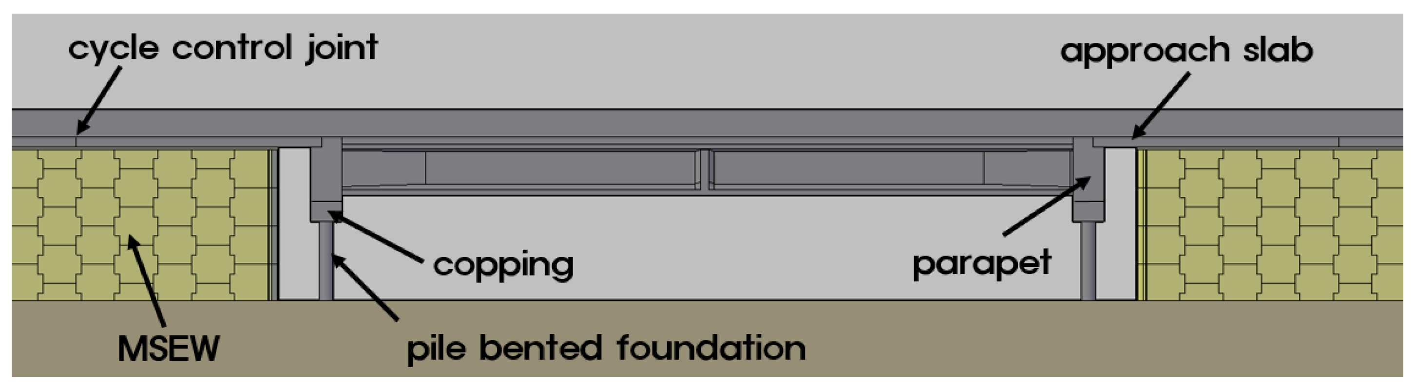
To overcome these IAB-associated problems, Nam, et al. [39] developed an integrated and pile-bent abutment with a mechanically stabilized earth-wall (IPM) bridge by combining the advantages of the IAB and the mechanically stabilized earth-abutment bridge, as shown in Figure 1 [2]. The super-structure of the IPM bridge is integrated with the abutment, and the vertical load of the super-structure and its lateral displacement are supported by the pile foundation, as is the case for a typical integral abutment. However, in the IPM bridge, the horizontal earth pressure is resisted by the mechanically stabilized earth wall (MSEW). By separating the earth pressure from the abutment, neither the fill-in front of the abutment, nor the non-compacted backfill, is needed. Furthermore, the piles in the IPM bridge form a pile-bent, and the protruded piles from the ground surface allow for decreased interaction with the member force of the pile-heads, in contrast to IABs [2,40].
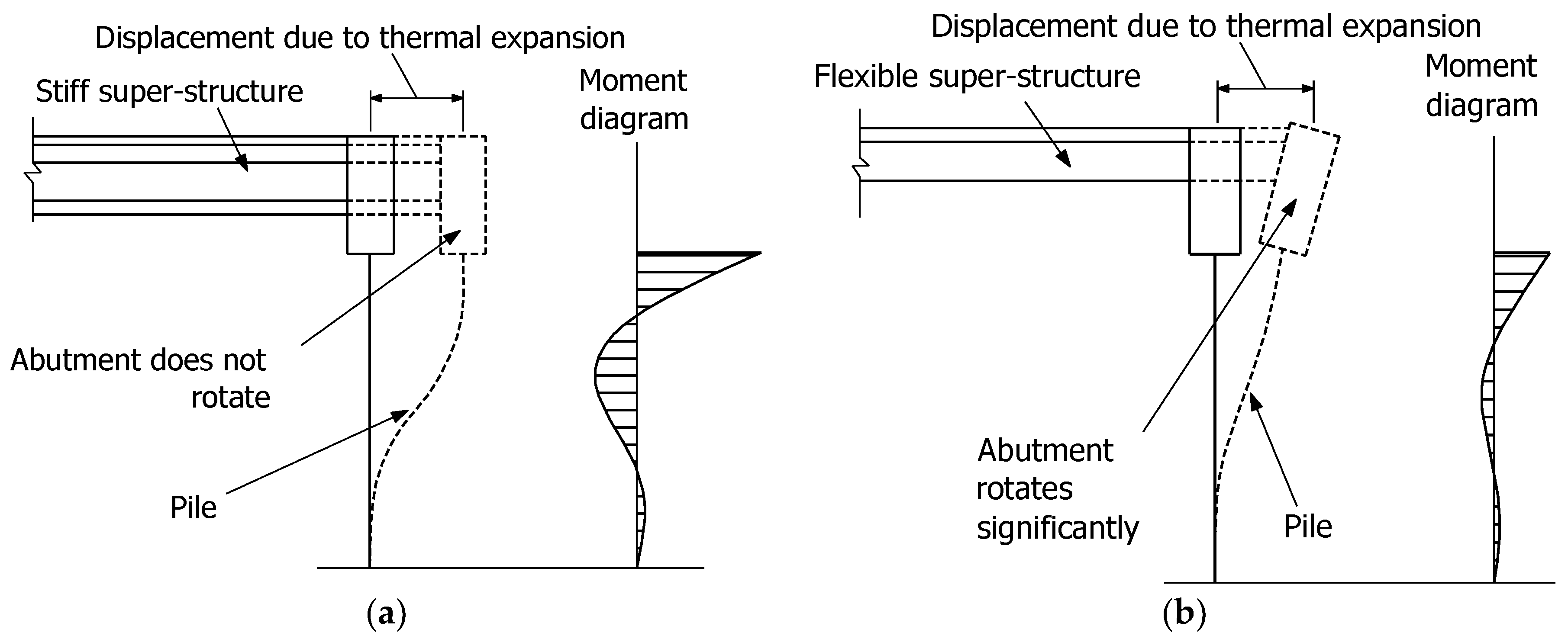
Based on the previous study of the IPM bridge (Park and Nam [2]), the PSC girder was used for the super-structure and the steel-pipe pile was used for the sub-structure for the IPM bridge; the length and the skew angle of the bridge, the height of the pile-bent extrusion, and the ground stiffness were selected as parameters, as listed in Table 1. The purpose of their analysis was to define the bridge behavior differences between the IPM and IAB, as well as to review their effects on bridge formation, pile protrusion height, and ground stiffness. The individual load effects were also reviewed. The results of the study by Park and Nam [2] show that lateral displacement caused by thermal expansion, drying shrinkage, and CR on the PSC girder are predominant in the IPM bridge, especially in regard to the behavior of the pile-bent. For the pile-bent, member forces decreased and lateral displacement increased when the pile protrusion height was increased. Moreover, most of the analysis focused on the bridge behavior involving the PSC girder and the steel-pipe pile, whereas the super- and sub-structural characteristics were not examined. The effect of thermal expansion (Δ Thermal) which occurs in the stiff super-structure of the IPM bridge is described in Figure 2a, whereas Figure 2b shows that the effect of abutment rotation occurring with a flexible superstructure is similar to that of the IPM bridge [31]. Consequently, the pile is governed by super-structural characteristics, whereas the bending moment on the pile is controlled by bending rigidity. Thus, the IPM pile-bent behavior could vary depending on the super- and sub-structural characteristics.
Accordingly, this study defined the IPM bridge behavior according to the super- and sub-structural characteristics. The parameters for the structural analysis include the super- and sub-structural types and the bending rigidity, as listed in Table 1. The analysis regarding the effect of shrinkage was conducted on the two types of super-structure—the influence of drying shrinkage on the PSC girder and the non-drying shrinkage influence on the steel girder. These shrinkage effects are also present in the steel-pipe pile and the cast-in-place (CIP) concrete piles, which are types of sub-structure. This served to review the effects of the super- and sub-structural characteristics, individually, in combination, and in response to thermal loads. In addition, the member forces and displacement that were imposed on the pile-head as well as the overall displacement were reviewed according to the super- and sub-structural characteristics, considering that the super- and sub-structures of the IPM bridge produce maximum member force on the pile-head.
2. Materials and Methods
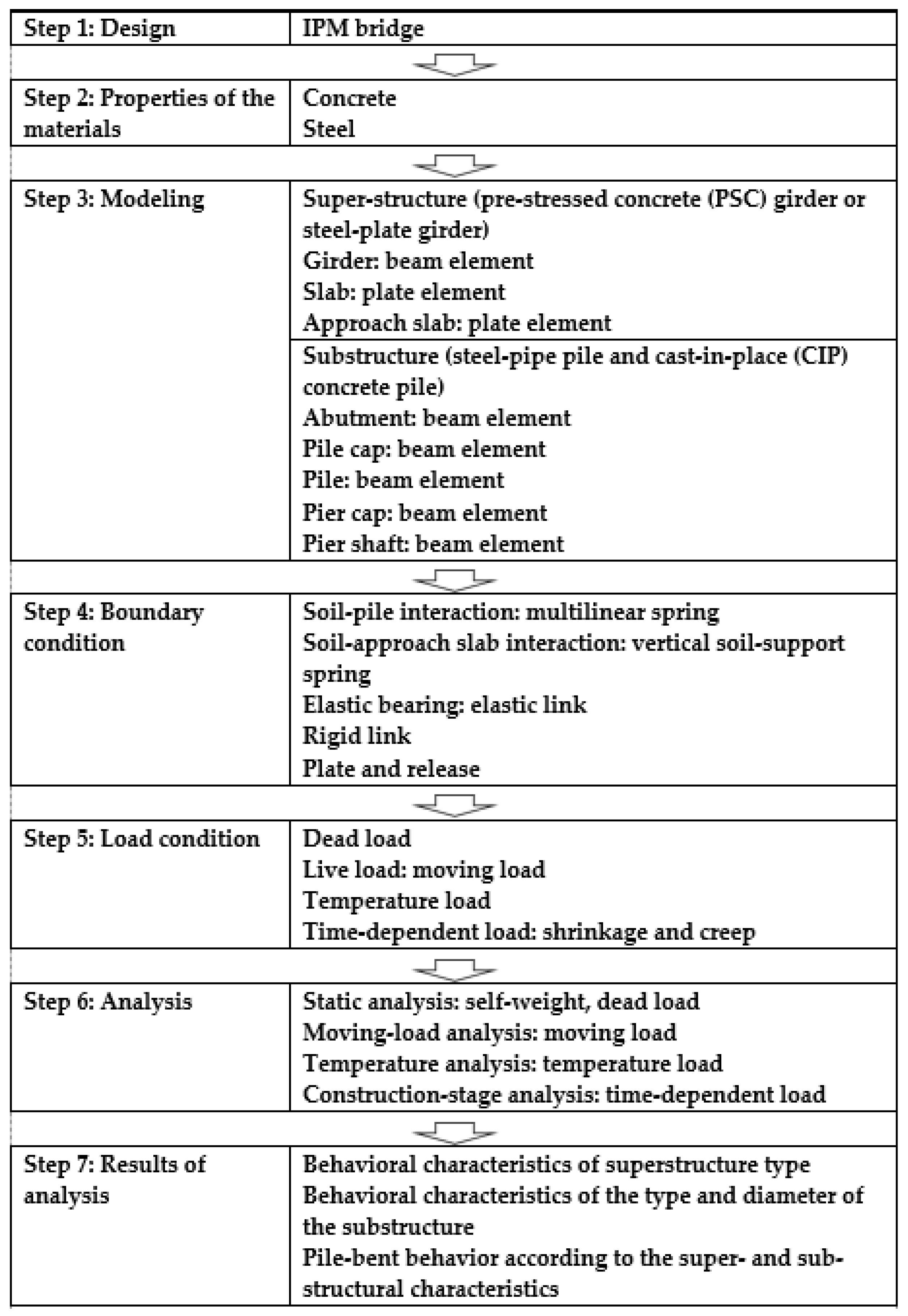
This study conducted a three-dimensional (3D) structural analysis in seven steps to define the IPM bridge behavior according to super- and sub-structural characteristics, as shown in Figure 3. In Step 1, the IPM bridge was designed. In Step 2, the material characteristics were input. In Step 3, the IPM bridge was modeled based on the design drawings. The IPM bridge model super-structure consisted of the PSC and steel-plate girders, whereas the sub-structure was comprised of steel-pipe piles and CIP concrete piles. The parametric analysis conditions for these materials are described in Figure 4. In Step 4, the boundary conditions were created. The soil-structure interaction needed to be identified to define the IPM bridge behavior in detail. In particular, the soil-pile interaction controls the pile-bent behavior that supports the super-structural lateral load. In Step 5, the loading conditions that were proposed in the design standards were set. In the IAB, like those of the IPM bridge, the thermal and time-dependent loads, including dry shrinkage and CR, needed to be specified; these are loading conditions common to both IAB and IPM bridges. In Step 6, a structural analysis was conducted on the IPM bridge model under loading conditions. In Step 7, the results were analyzed. For this study, the behavioral characteristics were reviewed according to the super-structure type, as well as the type and the diameter of the sub-structure. Moreover, the pile-bent behavior was reviewed according to the super- and sub-structural characteristics.
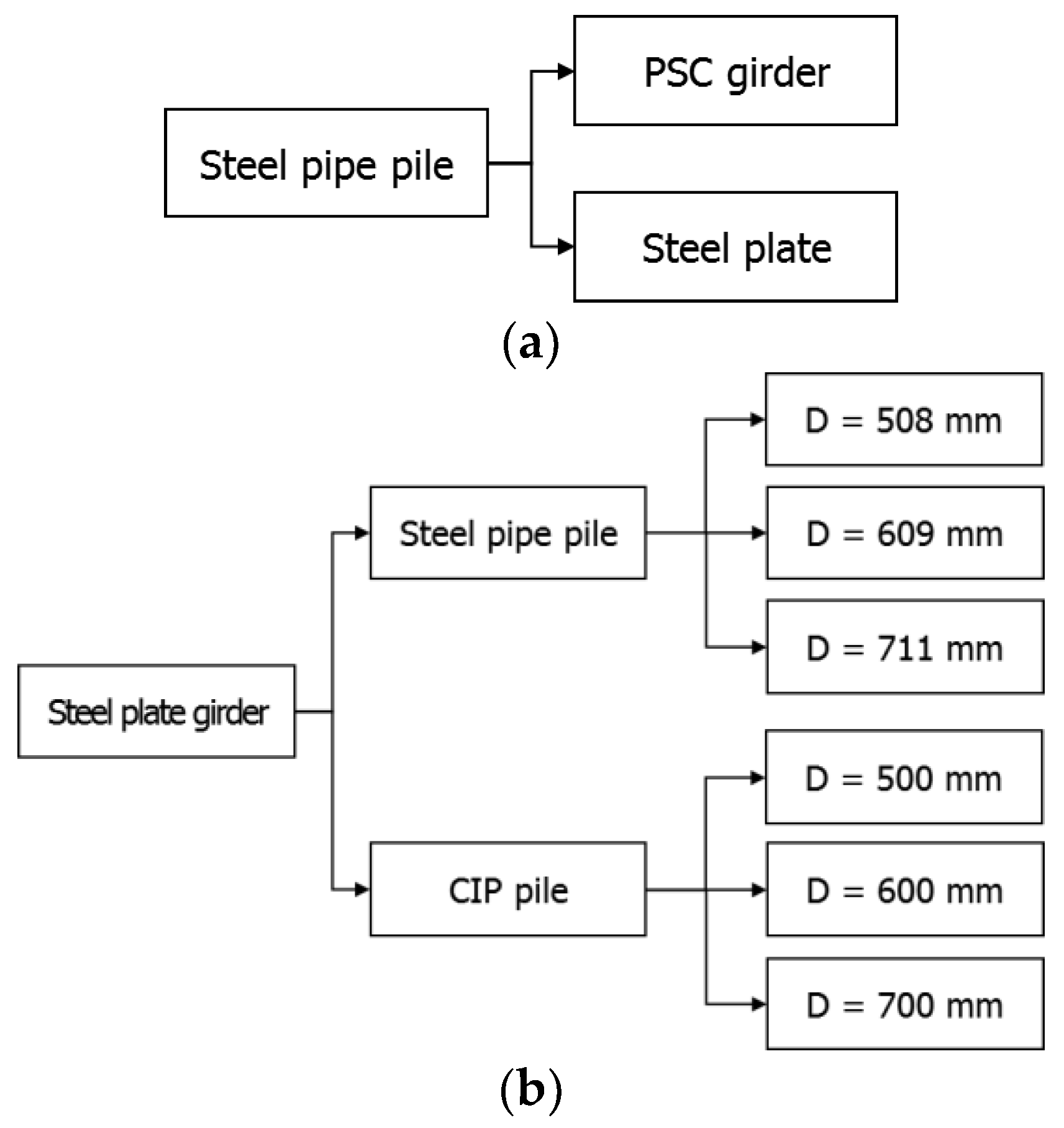
The parametric analysis conditions of this study are shown in Figure 4. The parametric analysis conditions for the examination of the IPM bridge behavior according to super-structure type are provided in Figure 4a. The structural analysis of the effect of the super-structural form was conducted by modeling the sub-structure as a 508-mm diameter steel-pipe pile, and the super-structure as PSC and steel-plate girders, respectively. The parametric analysis conditions for the examination of the IPM bridge behavior according to the sub-structure type and diameter are provided in Figure 4b. The IPM bridge behavior according to the sub-structural characteristics was analyzed by modeling the super-structure using a PSC girder and the sub-structures using steel-pipe piles and CIP concrete piles, respectively. At this point, the diameters of the steel-pipe and CIP concrete piles were increased from 508 mm to 711 mm, and 500 mm to 700 mm, respectively. In the structural analysis involving the PSC girder and the 508 mm diameter steel-pipe piles, the results reported by Park and Nam [2] were cited.
2.1. Bridge Analyses
The main subject of this study, the IPM bridge, is an integral form of the super-structure, abutment, and pile. The pile foundation is partially exposed as the abutment is separated from the backfill, and the earth pressure on the abutment is entirely supported by the MSEW. The design complies with the IPM Bridge Design Guidelines [41] that are based on ASSHTO (2002), ASSHTO (2012), VTrans [42], KECRI [33], MLTMA (2008), and MLTMA [43].
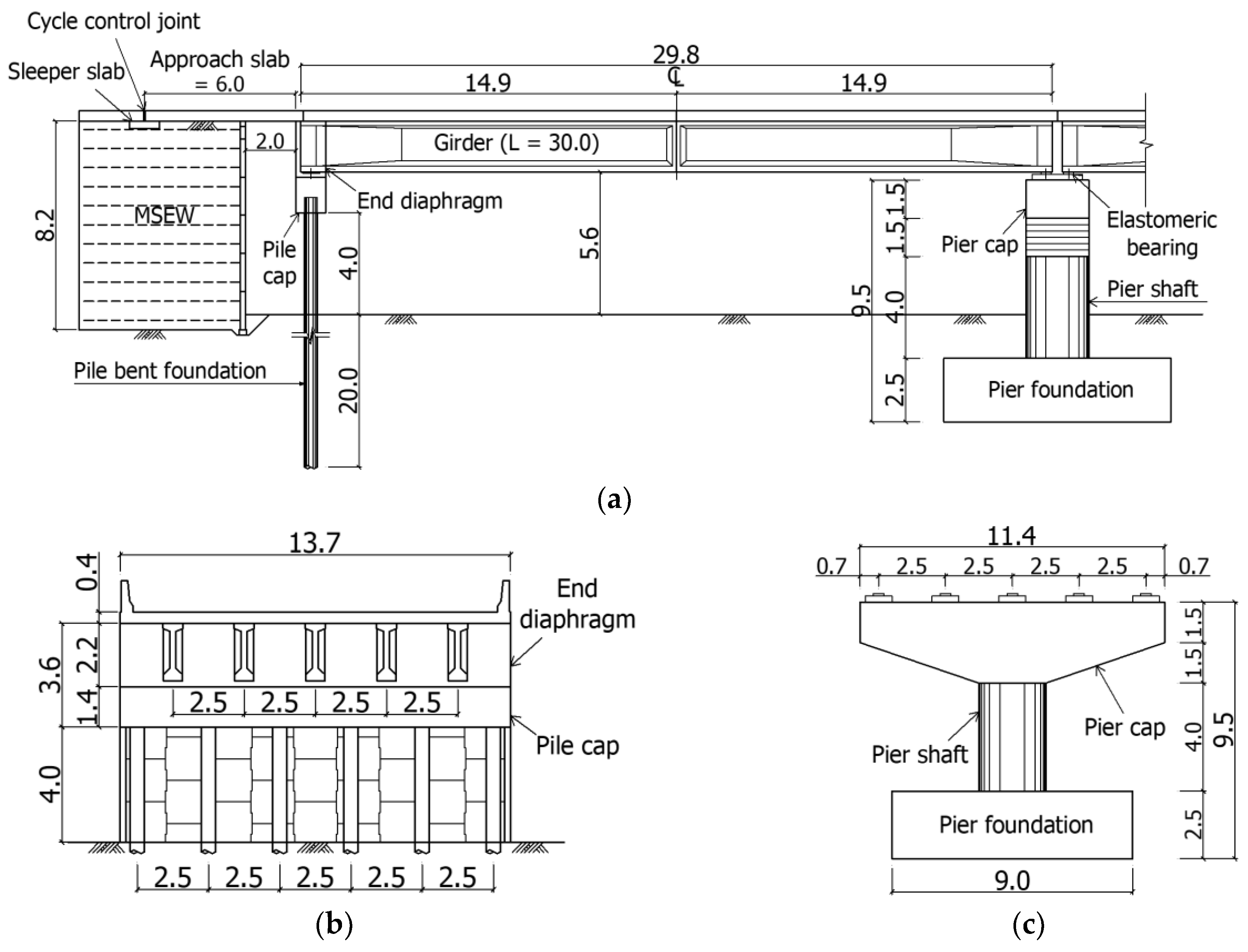
The span of the IPM bridge considered in this study is continuous and consists of four girders each having a span of 30 m to give a total bridge length of 120 m, as shown in Figure 5. It has no skew angle, and its sub-structure consists of two IPM abutments and three reverse T-type piers. The reverse T-type pier is a typical reinforced-concrete pier with a 4 m shaft height. A total of 10 elastomeric bearings, as movable bearings, were installed in the pier. The pile-bent foundation has a 4 m protrusion height and 20 m of penetration depth into the ground. The pile-head fixed in a pile-cap is 1.4 m to resist the bearing stress on the pile-head due to the weight of the super-structure. The width at the end diaphragm was integrated with the super-structure and was designed to be 2.2 m in consideration of the lateral girder displacement. The IAB end diaphragm was designed by taking into account passive earth pressure and is an important research item in the present study [6,7,8,9]. However, in the IPM bridge, the MSEW supports earth pressure and is therefore not a consideration in abutment design. The MSEW consists of panels and metal strips, each with a height and width of 8.2 m and 13.7 m, respectively. The super-structures of the IPM bridge are integrated into the end diaphragm, and the approach slab is connected by the dowel bar. A cycle control joint (CCJ) is installed at between the approach slab and the road pavement [40]. The CCJ replaces the expansion joints of general joint bridges and accommodates the temperature expansion of the super-structure. A sleeper slab is installed beneath the CCJ to prevent settlements of the approach slab.
Table 2 lists the bridge information and the ground conditions of the IPM bridge, as used in the structural analysis. As mentioned earlier, the bridge length is 120 m, the skew angle is 0°, and the pile protrusion length is 4 m. In the Standard Penetration Test (SPT), sandy soil ground conditions and an N-value of 20 were assumed. As for the structural analysis of the PSC girder and the steel-pipe pile under the conditions of the IPM bridge information listed in Table 1, the results of Park and Nam [2] are cited. Park and Nam [2] considered the effect of protruded heights of the pile-bent to be 4~10 m. However, only protruded heights of the pile-bent of 4 m were considered in this paper. According to Park and Nam [2], the lower the protrusion height that the pile-bent develops, the larger the bending moment. Hence, only the lowest protrusion height of 4 m was considered in this paper to investigate the behavior of the pile-bent according to the super-structure and the sub-structure.
2.2. Super-Structure Properties
For this investigation, the PSC and steel-plate girders properties were used to define the IPM bridge behavior according to the super-structural characteristics. The cross-section specifications of the girder in the structural analysis are provided in Figure 6 and Table 3. According to Olson, Holloway, Buenker, Long and LaFave [31], the super-structure rotation governs the member forces on the pile-head. In turn, the super-structure rotation is controlled by material properties, the girder height, and the end-diaphragm formation. Among the several influencing factors that were suggested by Olson, Holloway, Buenker, Long and LaFave [31], only the influence of material properties is considered in this study. The determination of the cross-sectional specifications was not made to produce major differences in the girder height, axial stiffness, and bending rigidity. Consequently, the behavioral characteristics were defined according to the material properties of concrete and steel that either create or do not create shrinkage (SH) and CR.
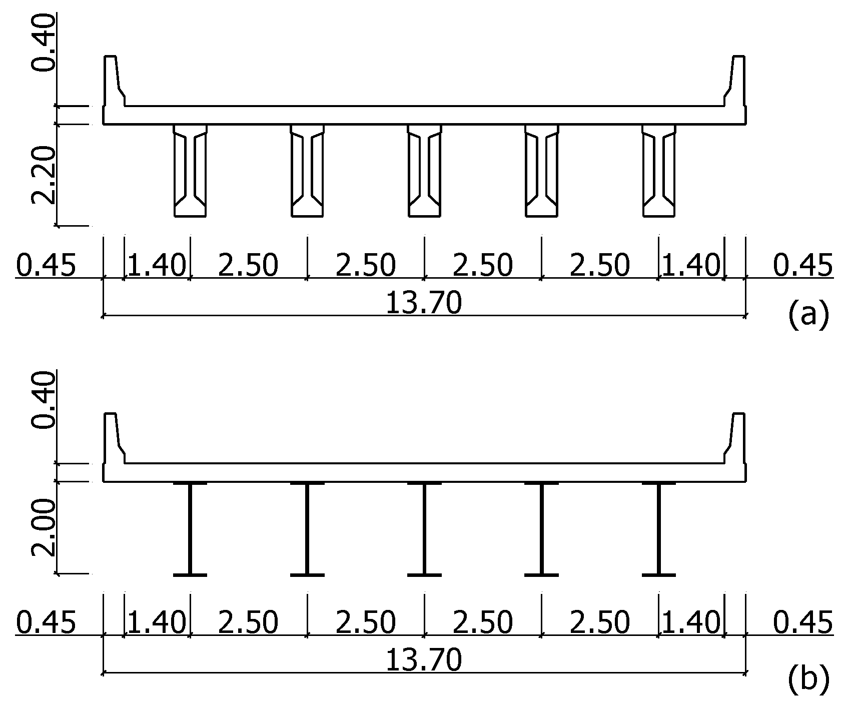
The PSC girder used in this study has a standard cross-section of 30 m and was developed by the Korea Expressway Corporation (KEC). As for the designed steel-plate girder, its height, axial stiffness, and bending rigidity are similar to those of the KEC PSC girder. The PSC and steel-plate girder heights are 2.2 m and 2.0 m, respectively. A slight girder height gap is present, whereas the modeled end-diaphragm formations are identical. The girders were placed in five equally spaced points at intervals of 2.5 m.
2.3. Sub-Structure Properties
Typically, for the IAB, the H-section pile is oriented at its weak axis to ensure flexibility in the lateral displacement of the super-structure [9,10,11,12,13,15,16,33]. However, in a skew bridge, it is difficult to precisely orient the pile at its weak axis as torsion is generated on the pile-head [2]. Therefore, the IPM Bridge Design Guidelines [41] recommend the use of steel-pipe pile as the pile-bent.
To define the IPM bridge characteristics according to the sub-structural characteristics, this study used a CIP concrete pile along with the other concrete materials, in addition to the steel-pipe pile, as recommended by the Bridge Design Guidelines [41]. The CIP concrete pile is widely used in single pile-bents of large-scale marine bridges. Hence, as a pile-bent, its behavior, according to its sub-structural characteristics, was defined via structural analysis. The thermal expansion, drying SH, and CR of the CIP concrete pile were not considered, while the IMP bridge behavior was defined only according to the bending rigidity of the sub-structure.
Table 4 lists the cross-sectional specifications of the pile-bents that were used in the structural analysis. The diameter of the steel pipe pile is from 508–711 mm with a thickness of 12.0 mm, whereas the diameter of the CIP concrete pile is from 500–600 mm.
3. Structural Model and Analysis Conditions
3.1. Introduction
The software that was used in the structural analysis is MIDAS Civil 2012 (MIDAS Information Technology Co., Ltd., Seongnam, Korea). The IPM bridge and the IAB have the same basic behavior mechanisms, but the IPM bridge pile-bent extrudes from the surface of the ground and is not affected by earth pressure. Therefore, in this chapter, a detailed description of the analysis model of the super- and sub-structural material properties, the interaction between the pile and the ground, and the boundary conditions between the approach slab and the ground are provided. The structural analysis model that was employed in this paper is the same as that of Park and Nam [2], except for the cross-sectional characteristics of the steel-plate girder and the CIP concrete pile. Regarding the load conditions, the dead, live, temperature, and time-dependent loads, such as the drying SH and CR, were considered [2].
3.2. Material Properties
The main structural members that were used in the IPM bridge structural analysis in this study were divided into concrete and steel. For concrete, the 28-day unconfined compression strength that was used for the CIP concrete pile, plate, abutment, and approach slab was 27 MPa, whereas 40 MPa was used for the PSC girder. The steel utilized for the steel-plate girder and steel-pipe pile is STK 490 class, as suggested in the Limit State Design of the Korean Bridge Design Code [43]. The PSC and steel-plate girders of the super-structure, and the CIP concrete and steel-pipe piles of the sub-structure were treated as variables. The material properties that were used in the analyses are listed in Table 5.
3.3. Modeling
The structural analysis model of the IPM bridge (Figure 7) was created by the design drawings in Figure 5 and references previous IAB studies [8,9,10,14,15,16,30,31]. The detailed structural analysis model of the IPM bridge is equivalent to the Park and Nam [2] model. The slab and the approach slab were modeled using the plate model, while the girder, end diaphragm, pile cap, pile, and pier were modeled using the beam model.
As for the boundary conditions of the analytical model members, the soil-pile interaction, soil-approach slab interaction, and elastic bearing were modeled using the multilinear spring, vertical soil-support spring, and elastic link, respectively. Using the rigid link, the slab and the girder were integrated for the super-structure, and the end diaphragm and the pile cap were integrated for the sub-structure. The IAB and IPM bridges were modeled using the plate and release option, thereby allowing the rotation of the abutment and the approach slab caused by their hinge-bar linkage. The modeling of the boundary conditions of the IPM bridge, such as that of the framework members, is the same as that of Park and Nam [2]. The soil-pile interaction and the soil-approach slab interaction are described in detail in Section 3.3.1 and Section 3.3.2, respectively.
The bearings were designed as elastic bearings, the specifications of which are the same as those of Park and Nam [2]. The elastomeric bearing specifications were 300 mm, 400 mm, and 89 mm for the width, length, and height, respectively, whereas the acceptable vertical load was 1350 kN. The elastomeric bearings were modeled as elastic links having compression-spring and shear-spring coefficients of 333.4 kN/m and 1840.0 kN/m, respectively, with an acceptable earthquake displacement of +90 mm. Also, the bearings were set as moving bearings in all directions.
3.3.1. Modeling of the Soil-Pile Interaction
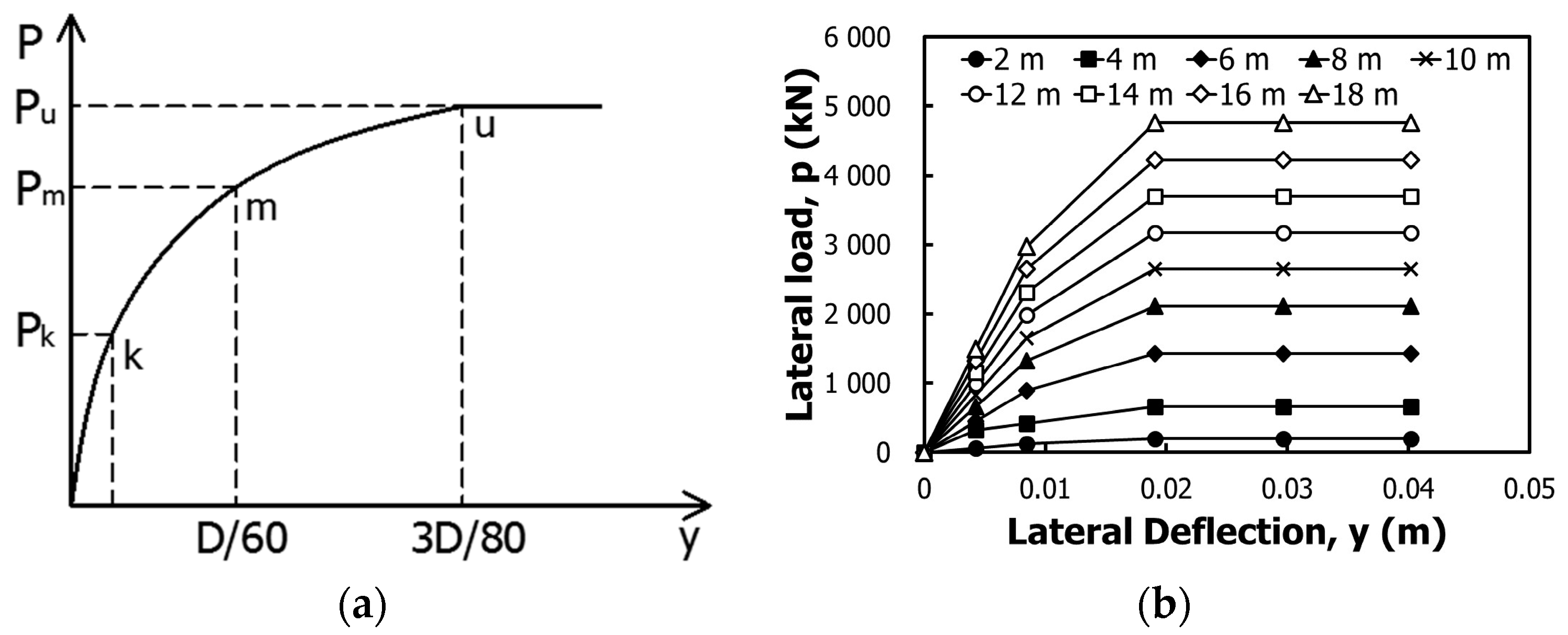
As the IPM bridge pile-bent resisted lateral loads, and as the lateral displacement of the pile increased, the surrounding soil showed nonlinear behavior, indicating that the yield state was finally reached. The nonlinear behaviors of the pile and the surrounding soil might be expressed by using the p-y curve that was suggested by Reese, et al. [44], as shown in Figure 8a. For this study, modeling of the p-y curve by Reese, Cox and Koop [44] that describes the nonlinear behavior of the pile and the surrounding soil was conducted using the multilinear spring of MIDAS Civil 2012, as described in Figure 8b. The comparison and validation of the p-y curve were conducted in accordance with the work of Park and Nam [2] via the p-y analysis program LPile version 5.0 [45,46] of Ensoft (Ensoft, Inc., Austin, USA), showing that the presented lateral behaviors of the pile for which the multilinear spring and the p-y curve were utilized were almost the same. Details on the MIDAS Civil 2012 p-y-curve modeling employing multilinear springs are found in the report of Park and Nam [2].
Park and Nam [2] used the 508 mm diameter steel-pipe pile and sandy soil with an SPT N-value of 10–50 in the pile-bent analysis. However, in this study, three different diameters for each of the steel-pipe piles and CIP concrete piles were used for the pile-bent, and ground stiffness was fixed at an N-value of 20. As described in Figure 8, the multilinear spring was modeled according to the type and specifications of the pile-bent suggested in Table 4 along with the p-y curve parameters given in Table 6. In MIDAS civil 2012+, p-y curves are implemented as multilinear springs. In this case, the required input values were the initial slope () according to the internal friction angle (), the relative compaction () of the soil, and the coefficient of horizontal soil reaction (), according to the bending stiffness of each pile. Please refer to Park and Nam [2] for the calculation of each property.
3.3.2. Modeling of the Soil-Approach Slab Interaction
The abutment of the IPM bridge is separated from the backfill soil by the MSEW, as described in Figure 1. However, the approach slab connected to the abutment by the hinge bar was placed on top of the reinforced retaining wall. Therefore, the approach slab is integrated with the super-structure, and the abutment moves according to the thermal expansion behavior of the super-structure, thereby producing friction with the ground beneath the approach slab, i.e., the interaction between the approach slab and the ground. To mimic the interaction between the approach slab and the ground, a vertical soil-support spring was modeled according to the procedure of Park and Nam [2].
The SPT N-value for modeling the vertical soil-support spring was set as 25, which follows the standard compaction criteria of the MSEW backfill, as suggested in the Expressway Construction Guide Specifications [47]. By using the SPT N-value of 25, the interaction with the vertical soil-support spring of 19,687.5 kN/m3 was selected, as suggested in the Structure Foundation Design Standards Specification [48]. The paper by Park and Nam [2] provides further details on the calculation of the vertical soil-support spring in the soil-approach slab interaction.
3.4. Loading Conditions
In addition to thermal expansion, which causes the lateral displacement of the super-structure as well as the CR and the drying shrinkage of the time-dependent load, consideration of the dead load (DL) and live load (LL) in the structural analysis of the IPM bridge is basically the same as in the IAB [2,10,15,30]. Each load condition complies with the Korea Bridge Design Code [49] of the Ministry of Land, Transport and Maritime Affairs (MLTMA) and the Standard Specifications for Highway Bridges [50] of the American Association of State Highway and Transportation Officials (AASHTO).
The temperature changes and values that were applied to the thermal load are listed in Table 7. For the PSC girder of the concrete bridge, the temperature range (−15~35 °C) of the cold climate region and its corresponding were used. The temperature upon construction was 10 °C, whereas it was 25 °C in summer, and −25 °C in winter. For the steel girder, the temperature range (−20~40 °C) of the cold climate region and its corresponding were applied. The temperature upon construction was 10 °C, whereas it was 30 °C in summer and −30 °C in winter.
The CEB-FIP [51] model code that is suggested in the Bridge Design Specification [52] was applied for the time-dependent load, drying SH, and CR of the PSC girder. The PSC girder material properties that were used with the CEB-FIP [51] model code are 40 MPa for the 28-day compression strength, 70% relative humidity, and normal Portland cement. Shrinkage occurred three days after concrete placement.
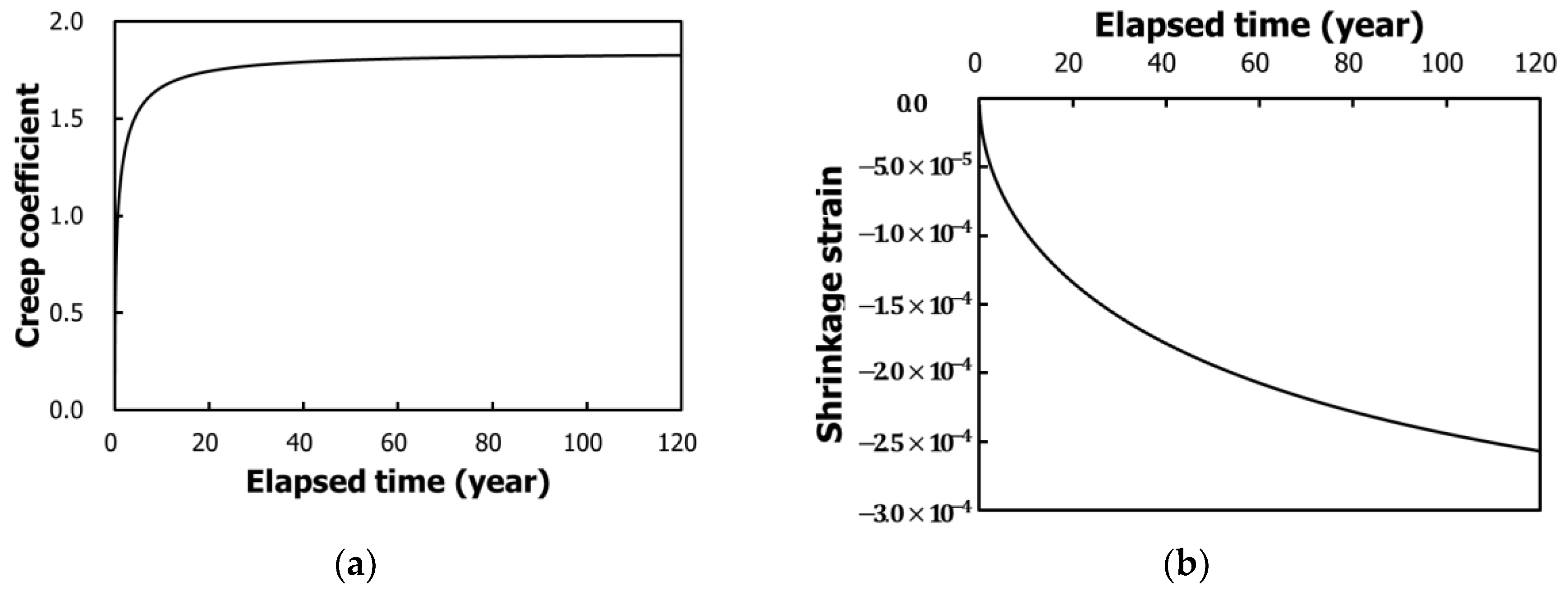
The shrinkage strain and CR coefficient calculations based on the CEB-FIP [51] model code, which are the same as those of Park and Nam [2], are provided in Figure 9. The analysis was conducted based on a service life of 120 years, or 20 years plus 100 years, which is the standard service life of Korean expressways. As shown in Figure 9a, the CR coefficient stabilizes over time after approximately 20 years. As can be seen in Figure 9b, the drying shrinkage induced strain rate was reduced to approximately −2.5 × 10⁻⁴ after 120 years.
3.5. Analysis Stage
The structural analysis stage was classified following the load conditions that were applied to the previously mentioned structural analysis model. The static analysis in which self-weight and DL were considered was conducted using MIDAS Civil 2012. The moving load and temperature analyses were also conducted. By considering the officially defined length of the service life of the IPM bridge, a construction-stage analysis, according to the 120-year time frame, was conducted regarding the time-dependent load, drying SH, and CR.
4. Analysis Results
Under fixed conditions, the design of the IPM bridge is the same as that of a typical IAB, where the pile supports the vertical and horizontal loads, moments, and vertical and horizontal displacements, whereas the pile-bent is integrated into the abutment as the fixed condition. Under such a fixed pile connection condition, the largest bending moment occurred in the pile-head. Therefore, the pile-head stress should not exceed its acceptable stress level [31,33,41].
The results of the structural analysis that was conducted in this study show that the applied bending moment and displacement on the pile-head are the same as those described by Park and Nam [2]. In the parametric analysis, the effects of the individual and combined loads in terms of the super-structure type were first identified. Then, the effects of pile type and diameter were identified according to the super-structural characteristics. The IPM bridge is an IAB type that integrates the super-structure and sub-structure. Therefore, the super-structure has expansion and contraction movements according to the seasonal temperature changes. Therefore, the structural analysis results of the IPM bridge were classified into expansion (summer) and contraction (winter).
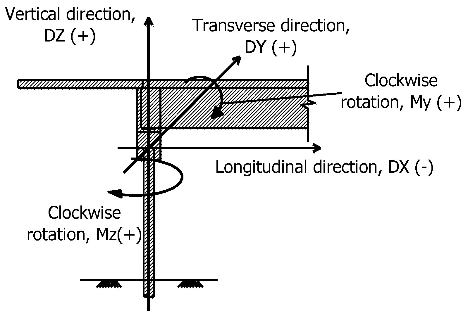
The sign convention suggested by Park and Nam [2] and complied with in the present study, is provided in Figure 10. The displacement value in the longitudinal direction was negative (−) when the value was shrunk along the x-axis, and its value was positive (+) when it was expanded toward the back face of the abutment. The displacement value in the transverse direction is positive (+) when it occurred on the left side and negative (−) when it occurred on the right side. The bending moments that acted on the pile-bents in the direction of the rotation of the super-structure girder, subsequently defined as My in this present study, are positive (+) when their direction is clockwise and negative (−) when rotation is counter-clockwise. As for the moment that causes torsion on the pile-bent foundation, subsequently defined as Mz in the present study, the moment is positive (+) when it occurs in the clockwise direction and negative (−) when it is in the counter-clockwise direction.
4.1. Pile-Head Behavior According Super-Structure Types
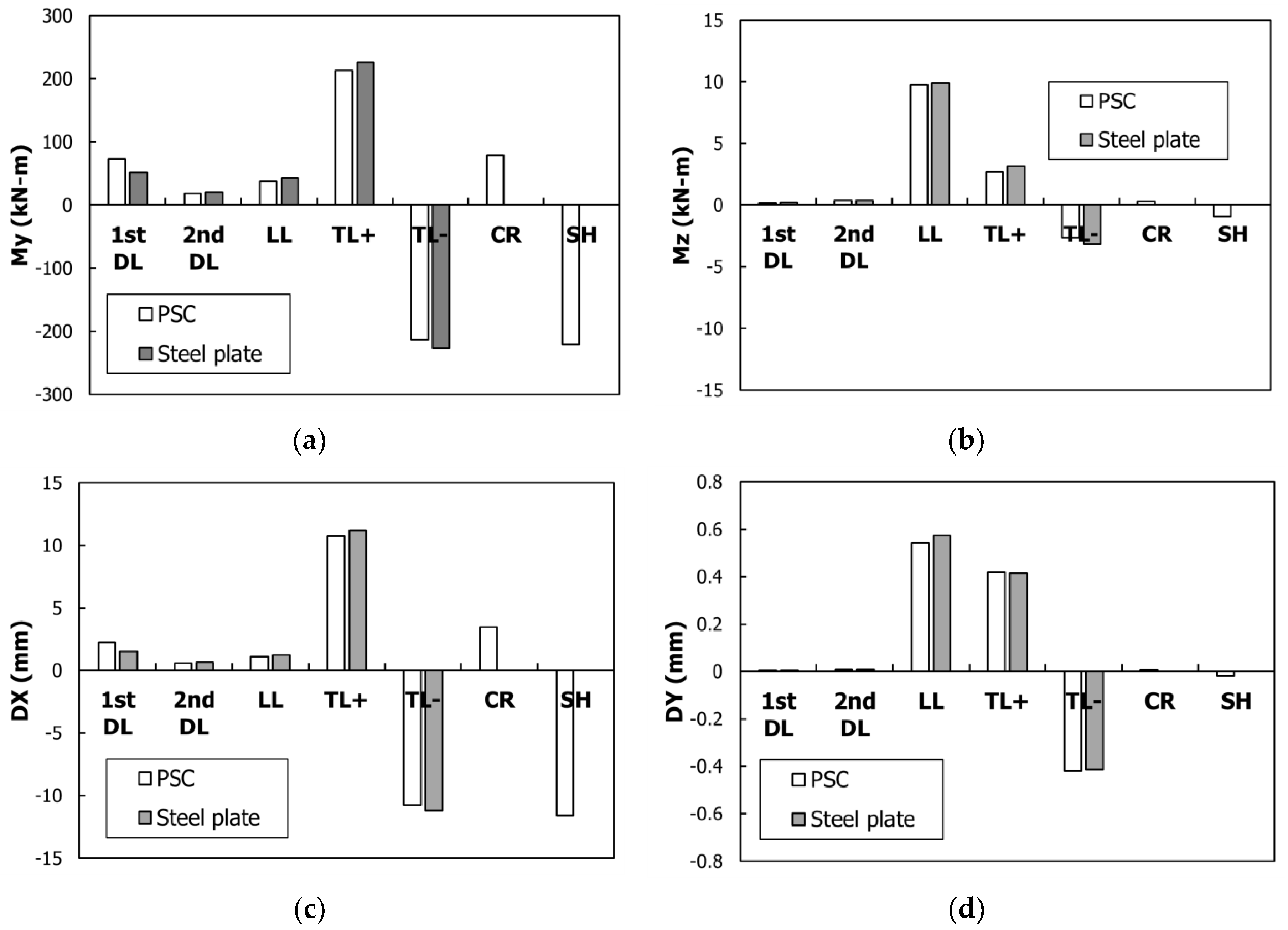
The behavior that occurs in the pile-head under individual conditions, per super-structure type, is shown in Figure 11. The structural analysis was conducted by modeling the sub-structure with a 508 mm diameter steel-pipe pile, and the super-structure with the PSC and steel-plate girders, respectively. The My bending moment acting on the pile-head is shown in Figure 11a. Comparing the PSC and steel-plate girders, the first DLs are bigger in the PSC girder than those in the steel-plate girder. This is because the cross-sectional area of the PSC girder is larger compared with that of the steel-plate girder. The temperature load (TL) is bigger in the steel-plate girder with a relatively higher . Moreover, the time-dependent loads, SH, and CR occurred in the PSC girder only. The individual loads that exerted the greatest effect on the My bending moment of the PSC girder, enumerated in the same sequential order as that of Park and Nam [2], are temperature increase (TL+), temperature decrease (TL−), SH, and CR. In the steel-plate girder, the greatest effects were from the TL+ and the TL−.
The Mz bending moment that acted on the pile-head as torsion is shown in Figure 11b. In both the PSC girder and steel-plate girder, the loads LL, TL+, and TL− were respectively applied. The longitudinal displacement of the pile-head (DX) is shown in Figure 11c. In the same way that the My bending moment is shown in Figure 11a, the TL+, TL−, SH, and CR were respectively applied in the PSC girder. In the steel-plate girder, the TL+ and the TL− showed the greatest effects. The pile-head transverse displacement (DY) is shown in Figure 11d. In the same way that the My bending moment is shown in Figure 11b, the LL, TL+, and TL− were respectively applied.
Consequently, the time-dependent loads, SH, and CR were applied in the PSC girder. The My bending moment and the DX of the pile-head, and the Mz bending moment and the DY that were applied as torsion, produced equal individual-load effects.
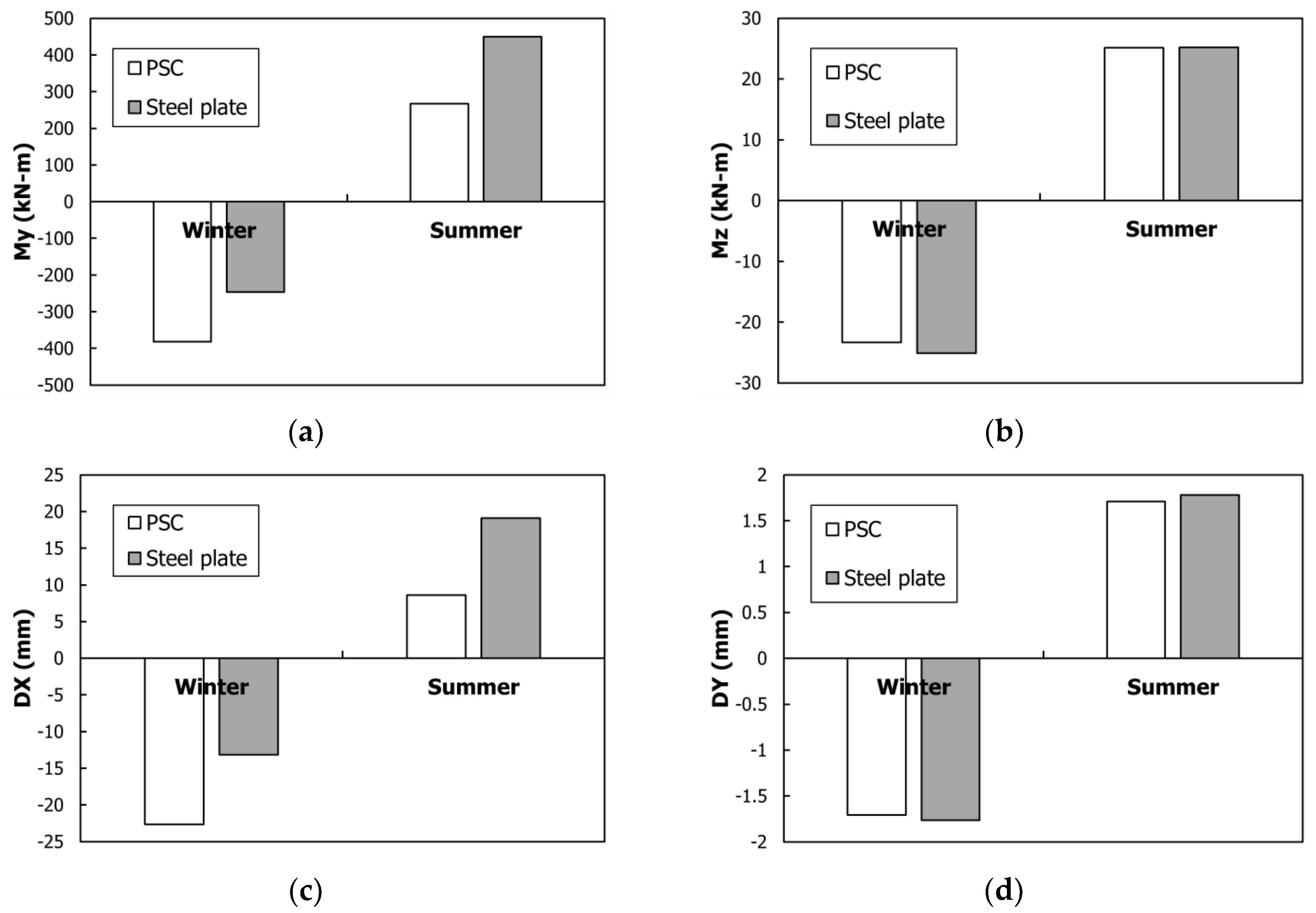
The effect of the combined load per super-structure type on the pile-head is shown in Figure 12. As suggested by AASHTO [50], the individual loads in Figure 11 make up the combined load of 1.3 DL + 2.15 LL + 1.3 TL + 1.3 SH + 1.3 CR. At this point, TL was classified either as TL+ or TL−. Therefore, the summer case involved a TL+ combination, whereas the winter case involved a TL− combination. The purpose of the consideration of the seasonal behavior of the IPM bridge is that contraction and expansion occur according to individual loads, as described in Figure 11, and when the individual loads are combined, the combination actually acts on the IPM bridge. Figure 12a shows the My bending load that was applied to the pile-head. A major application of the PSC girder was in the winter case, whereas a major application of the steel-plate girder was in the summer case. The reason for the major application of the PSC girder in the winter case is described in Figure 11a, wherein the effects on the SH and the TL− are evident. In contrast, the expansion that decreased in the PSC girder in the summer case is due to a combination of the TL+ and SH. Accordingly, for the steel-plate girder in the summer case, a smaller My occurred. The effect of the individual loads shown in Figure 11 is the same as the behavior of DX and is almost the same as that of My.
The Mz that acted on the pile-head as torsion is shown in Figure 12b. The Mz of the steel-plate girder is greater than that of the PSC girder in the winter case, whereas both are almost the same in the summer case. As described in Figure 11a, the My of the PSC girder is greatly influenced by the time-dependent loads, whereas Mz is hardly influenced by the time-dependent loads. Accordingly, the application of Mz as torsion in the winter case is significantly advantageous for the steel-plate girder with a relatively large . The effect of the individual loads, shown in Figure 11, is the same as the DY behavior and almost the same as that of the My behavior.
According to Park and Nam [2], TL+ and TL− as well as the time-dependent loads, SH, and CR, increase as the bridge length increases. Therefore, an applicable bridge-length limit applies not only for the IPM bridge but also for the IAB, as listed in Table 8. Based on the maximum span limits listed, the length limit of the concrete-bridge with a thermal expansion is longer than the limit of the steel-girder bridge. However, in view of the review of the combined load effects of the IPM bridge based on the super-structure type, the contraction-based deformation in the PSC bridge, which is influenced by the time-dependent loads, drying shrinkage, and CR, compared with that in the steel-plate girder, is greater, resulting in a greater pile-head My bending moment. In particular, owing to the major TL and SH effects, the magnitude of the My bending moment on the pile-head that was imposed by the super-structural contraction of the PSC girder is greater than that in the steel-plate girder. Therefore, the IAB and IPM bridge extensions need to be rechecked in the review of the drying shrinkage and CR effects, based on Table 8.
4.2. Effect of the Pile-Head by the Pile Type and Diameter
4.2.1. Effect of the Pile Type
In this section, the bending moment and the displacement of the pile-head according to the pile type is reviewed, where the PSC girder representing the time-dependent behavior is set as the super-structure.
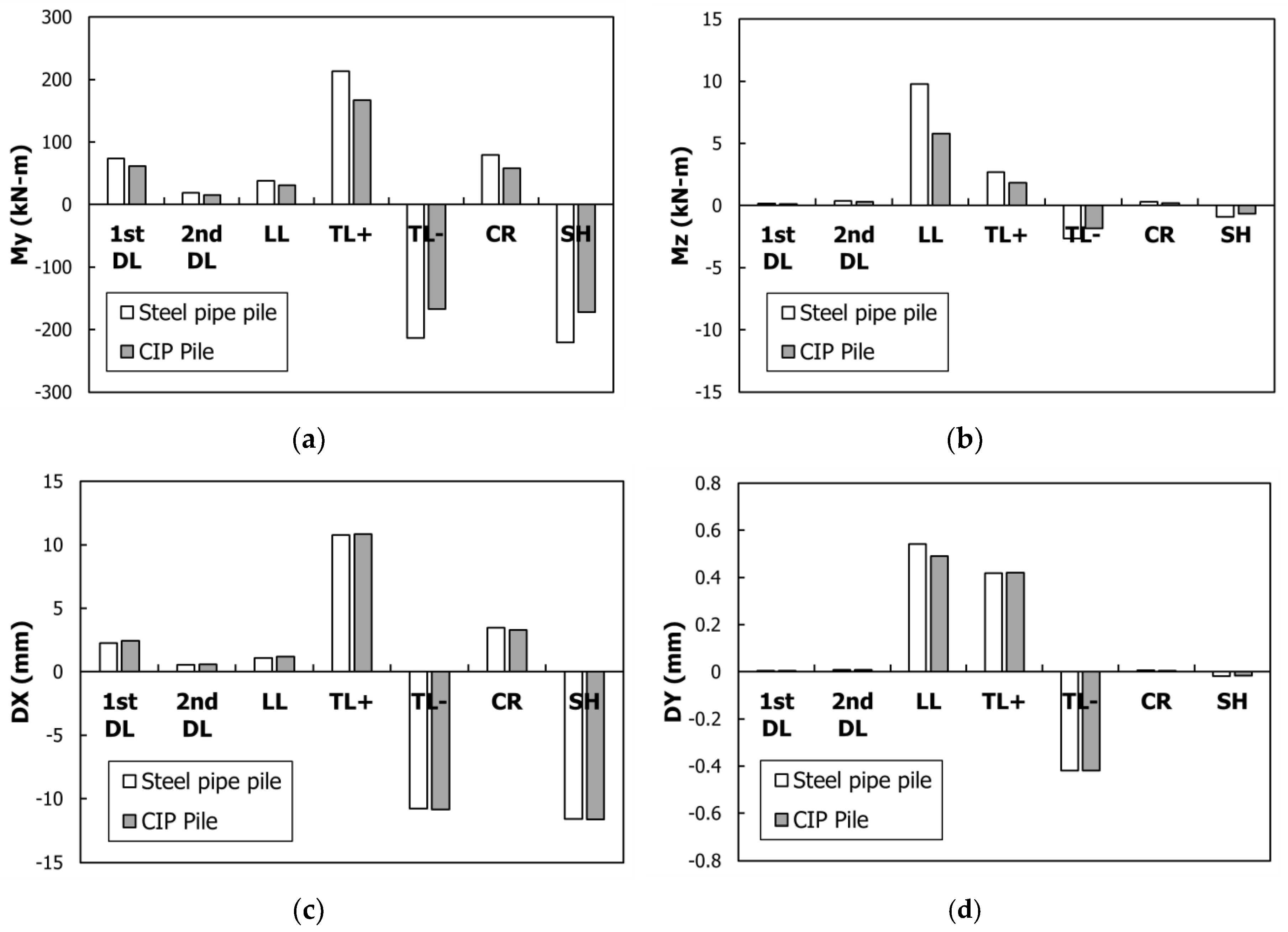
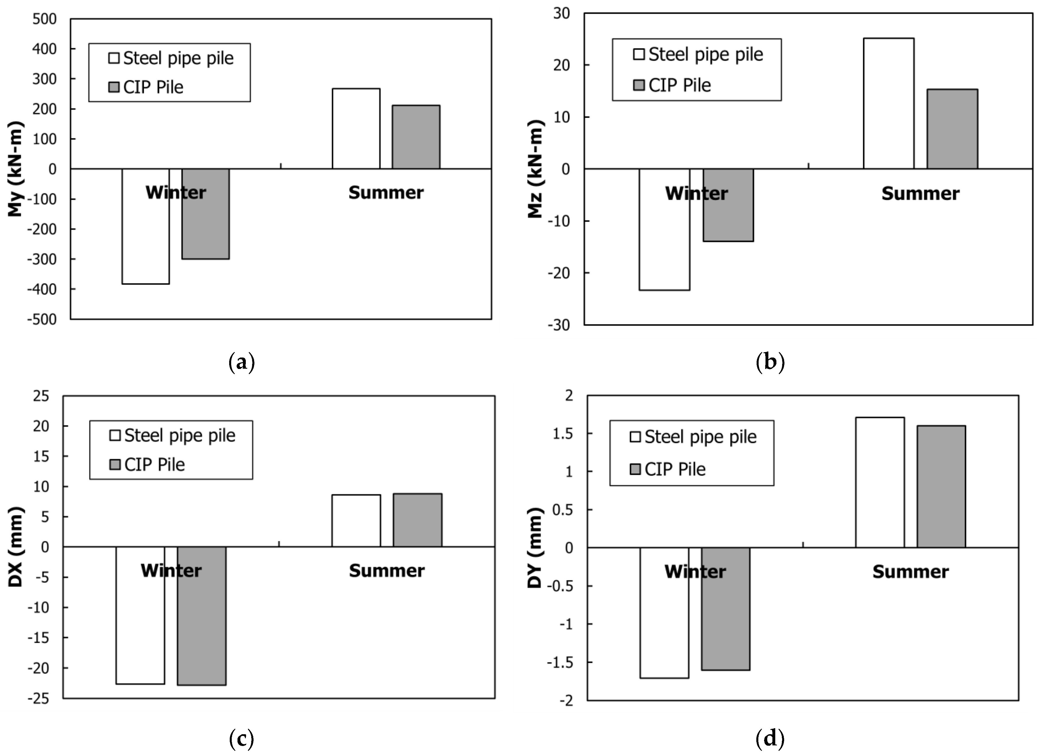
The individual load effect by pile type is shown in Figure 13. The moments, My in Figure 12a and Mz, applied as torsion in Figure 13b, are large in the steel-pipe pile. However, the DX in Figure 13c and the DY in Figure 13d are nearly the same in the steel-pipe pile and the CIP concrete pile. Thus, a difference in the individual load effect by pile type is nonexistent, in contrast with the effect of the type of super-structure. This is because the IPM bridge sub-structure is controlled by the super-structural characteristics, as described in Figure 2 [31].
The combined load effects according to the super-structure type were reviewed as described in Figure 14. As suggested by AASHTO [50], the combined load of 1.3 DL + 2.15 LL + 1.3 TL + 1.3 SH + 1.3 CR was obtained using the individual loads, as shown in Figure 13. Under this combined load, the bending moment was large in the steel-pipe pile, whereas the displacements were almost the same in the steel-pipe and CIP concrete piles. The bending-stiffness (EI) values listed in Table 3 are for the 508 mm diameter steel-pipe pile and for the 500 mm diameter CIP concrete pile. Therefore, the bending moment of the steel-pipe pile with the relatively greater EI was calculated to be large.
4.2.2. Effect According to the Pile Diameter
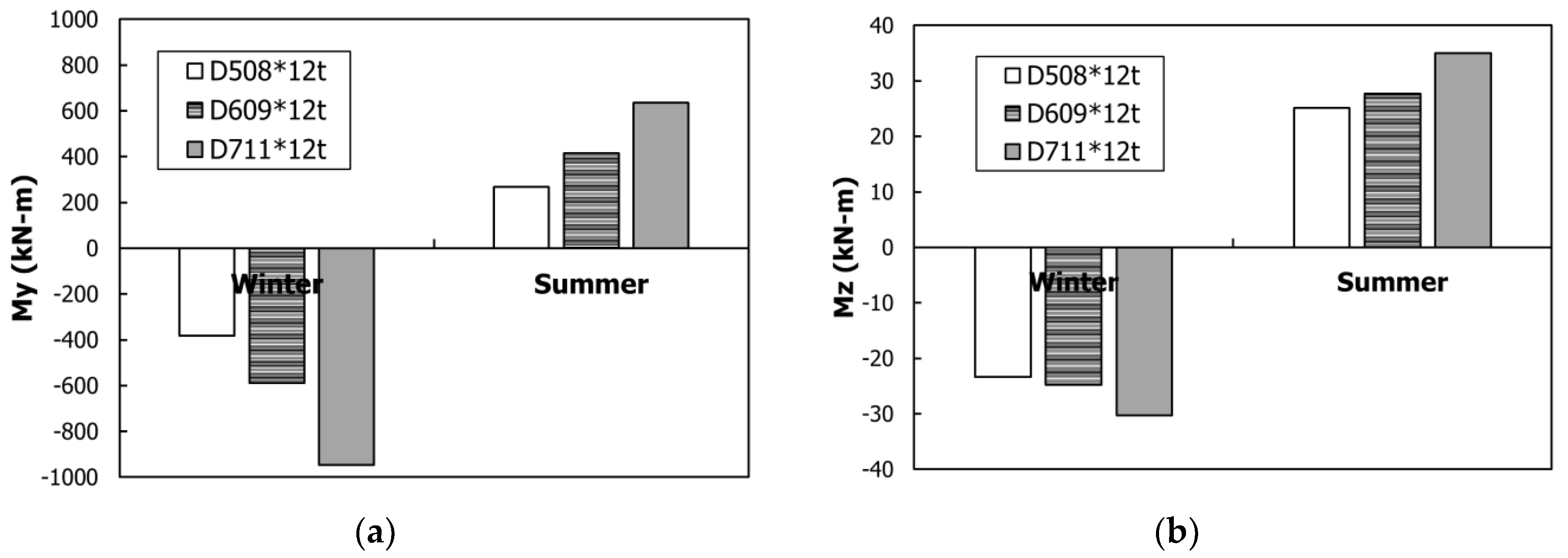
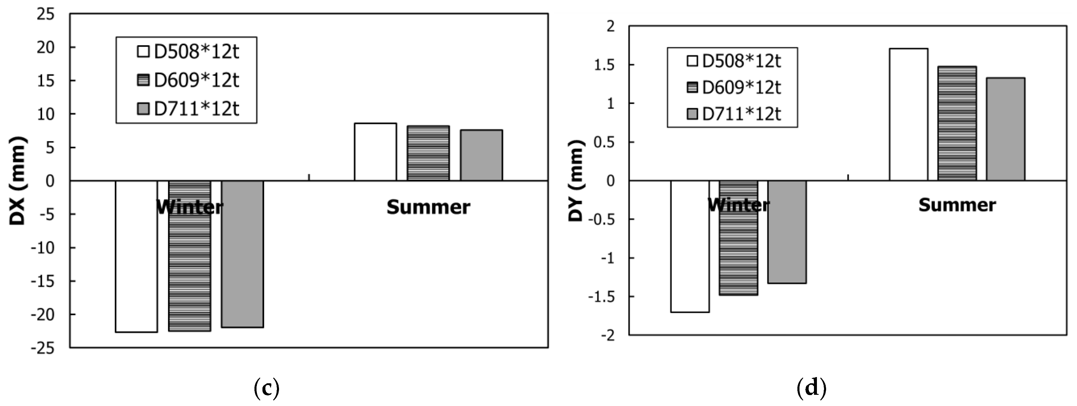
In this section, a review of the combined load effect according to the diameter of the steel-pipe and CIP concrete piles is presented. The analysis was conducted in three steps with a 100 mm increase in the pile diameter per step, starting at 508 mm for the steel-pipe pile and 500 mm for the CIP pile. The bridge super-structure was the PSC girder. The combined load effects according to the diameter of the steel-pipe pile and CIP concrete pile are shown in Figure 15 and Figure 16, respectively. For both pile types, as the diameter of the pile-head was increased, its EI increased, whereas the displacement decreased. This phenomenon occurred because the super-structural lateral displacement was resisted by the EI of the pile-head.
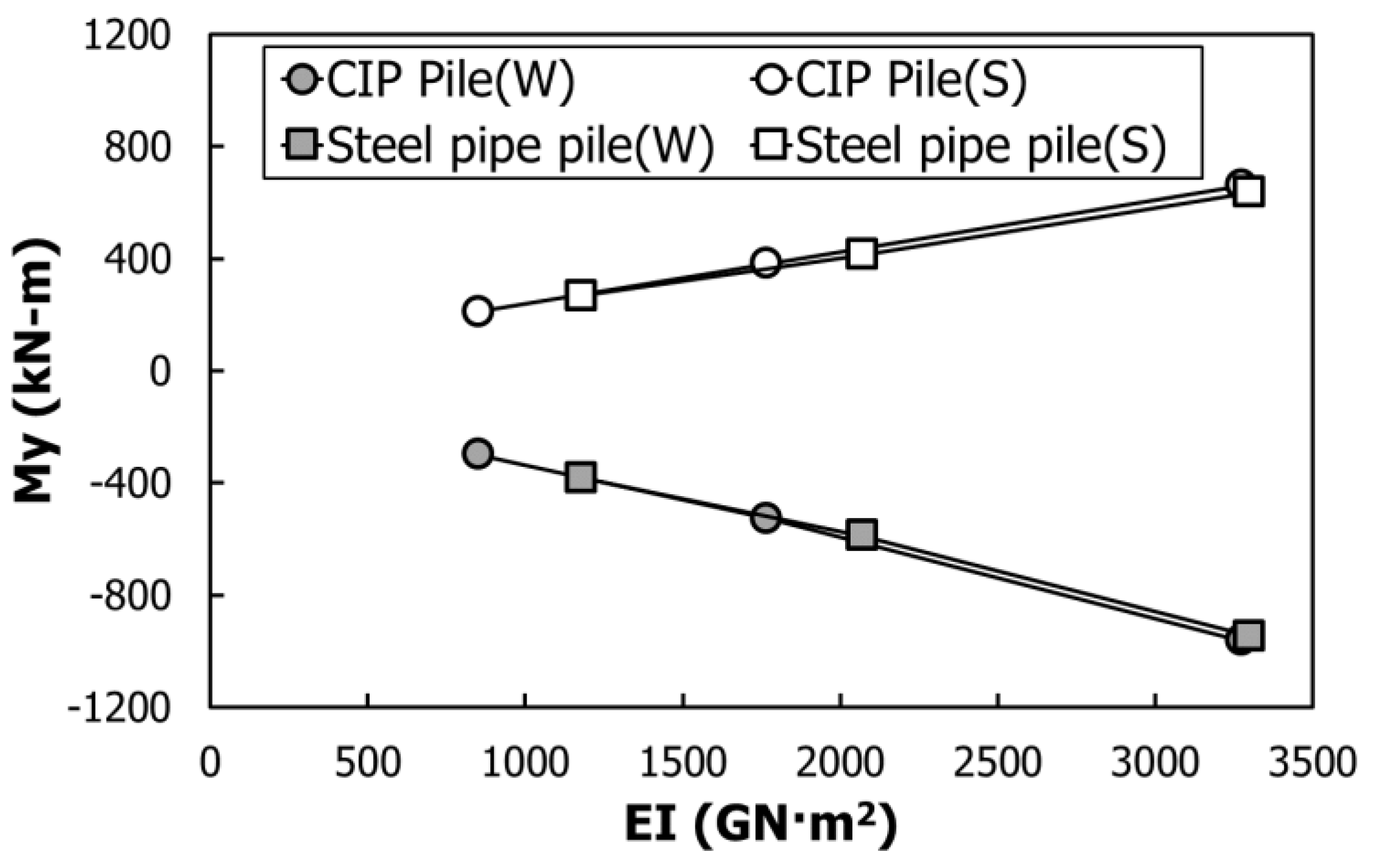
The change in the pile-head bending moment according to the bending rigidity of the steel pile and CIP pile is shown in Figure 17. In this figure, W and S refer to the winter case and the summer case, respectively. Flexural stiffness and allowable bending moments of piles are the main design factors when designing the pile of IPM bridge. The bending moment increased linearly as the bending rigidity increased, regardless of the pile material. Owing to the design of the IPM bridge, the structural analysis yielded a linear increase in the bending moment. Consequently, the bending moment occurred in the pile according to the bending rigidity, regardless of the material type, which is different from that in the super-structure. The IPM Bridge Design Guidelines [41] recommend using steel pipe piles because of their flexibility. Since steel pipes increase the flexural stiffness based on the diameter, the optimum pile should be selected through the p-y analysis, as shown in the IPM Bridge Design Guidelines [41].
4.3. Pile-Bent Behavior According to the Characteristics of the Super- and Sub-Structures
This section reviews the pile-bent behavior according to the super- and sub-structural characteristics. In the IPM bridge, the super-structure is integrated with the sub-structure, and expansion and contraction can occur in the super-structure due to seasonal temperature variations. If the individual loads are combined, the IPM bridge appears to show different summer and winter behaviors [2]. To identify the pile-bent behavior versus the seasonal behavior of the IPM bridge, the contraction and expansion behavior of the pile-bent was calculated according to the summer TL+ and the winter TL−. As suggested by AASHTO (2002), 1.3 DL + 2.15 LL + 1.3 TU + 1.3 SH + 1.3 CR was used as the load combination.
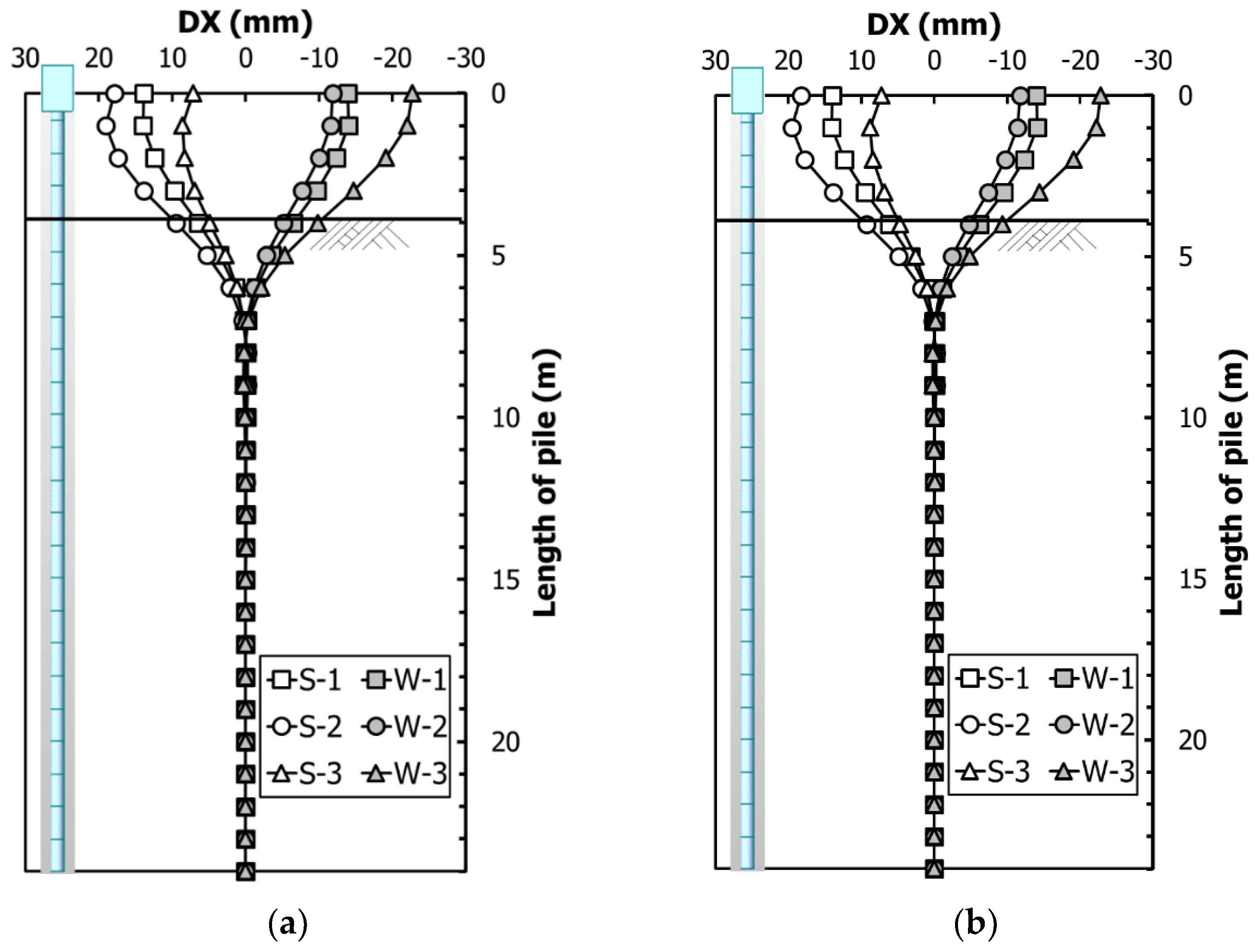
The longitudinal-displacement behavior versus the seasonal thermal load according to the pile type that supports the PSC girder is shown in Figure 18. In Figure 14, S−1 and W−1 indicate the TL+ and the TL−, respectively; S−2 and W−2 are combinations of the TL, DL, and LL, and S−3 and W−3 add the time-dependent loads, such as the drying SH and the CR. The temperature was set as −15 °C for winter and +35 °C for summer, with a temperature change that is based on an installation temperature of 10 °C so that it remains within ±25 °C.
The seasonal behavior of the steel pile in the PSC girder is shown in Figure 18a. The figure also cites the results that were suggested by Park and Nam [2]. According to Park and Nam [2], the DX of the pile-bent in the cases of S−1 and W−1 is ±13.92 mm, and showed symmetry in the drying SH and expansion behaviors. When the DL and the LL were applied, girder deflection and abutment rotation occurred, and DX showed an increase toward the back of the abutment. In S−2, the summer TL+ showed a displacement of +17.93 mm, whereas in W−2, the winter TL− showed a displacement of −11.89 mm. The DX value that is shown in Figure 18b is almost the same as the value that was identified from the seasonal behavior comparison between the CIP pile and the steel pile, shown in Figure 14c.
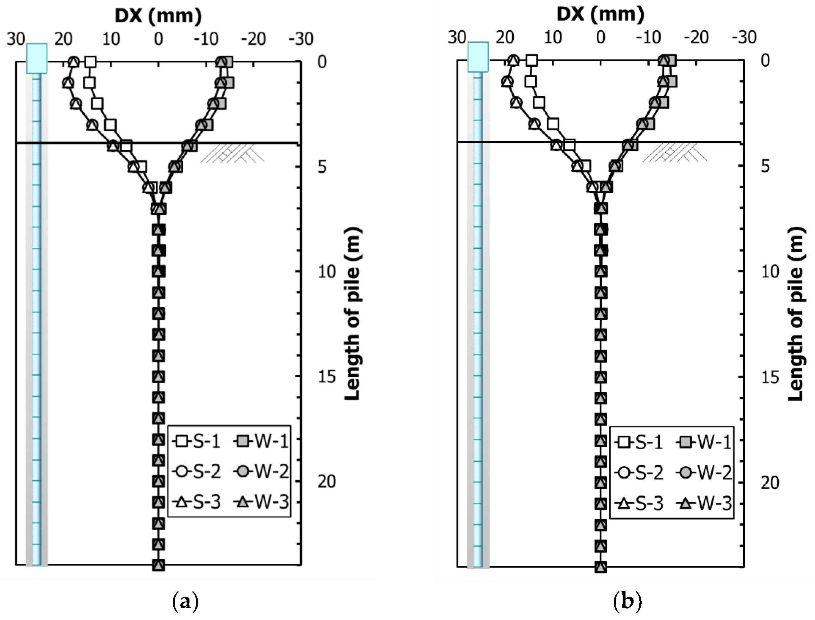
The DX behavior versus the seasonal thermal load according to the pile type that supports the steel-plate girder is shown in Figure 19. Comparing the results between the PSC girder shown in Figure 18a, and the steel-plate girder shown in Figure 19a, where both girders are being supported by the same steel pile, it is seen that expansion is greater than contraction in the steel-plate girder without the time-dependent loads (S−3 and W−3). This result is the same as that of the super-structure-type effect shown in Figure 12. In the comparison between the seasonal behaviors of the steel pile in Figure 19a and the CIP pile in Figure 19b, where both piles supporting the steel-plate bridge, a behavioral difference is not evident. This is the same as the PSC girder results shown in Figure 18.
5. Discussion
This paper identified IPM bridge behaviors based on the bridge’s super- and sub-structural characteristics. Based on the analysis results of the IPM bridge, the behaviors of the IPM are as follows:
- (1)
- As a result of the review of the individual load effect according to the super-structure types, the individual loads that exerted the most significant effects on the My bending moment of the PSC girder were respectively TL+, TL−, SH, and CR, which is in the same order as that reported by Park and Nam [2]. In the steel-plate girder, the TL+ and the TL− had the greatest effects. The My bending moment on the pile-head and DX, and the torsional Mz bending moment and DY showed equal individual load effects.
- (2)
- The review of the combined load effects of the super-structure types shows that the PSC girder has considerable influence in winter, whereas the steel-plate girder has considerable influence in summer. The significant influence of the PSC girder in winter is due to the SH effect and the TL−. In contrast, the expansion of the PSC girder in summer is decreased due to the combination of the TL+ and SH. Accordingly, the My bending moment that occurred in the summer case was less than that of the steel-plate girder. Identical to the individual load effect, the DX behavior was almost the same as that of the My bending moment.
- (3)
- From the review of the effects according to the super-structure type, it was found that the My bending moments of the PSC girder and the-steel plate girder were influenced by the occurrence of the time-dependent loads. In particular, owing to the major effects of TL and SH, the pile-head My bending moment effected by the super-structural contraction was greater in the PSC girder than that in the steel-plate girder. Consequently, as time-dependent loads were applied, the contraction behavior of the PSC girder super-structure in winter was large and the expansion behavior of the steel-plate girder in summer was also large. In the behavioral comparison between the IAB and the IPM bridge, the expansion displacement of the super-structure was prevented due to the earth pressure in the IAB. However, it was not constrained in the IPM bridge, as the earth pressure was supported by the MSEW. Therefore, the IPM bridge’s thermal expansion is the same in summer and winter.
- (4)
- In reviewing the individual load effect in the IPM bridge according to pile typs, a difference was not detected. This is because the sub-structure of the IPM bridge is controlled by the super-structural characteristics. However, in the review of the effect of the combined loads according to the pile type, the bending moment in the steel-pipe pile was large, whereas the displacements of the steel-pipe and CIP piles were almost the same.
6. Conclusions
The IPM bridge was developed to overcome problems of general integral abutment bridges by separating earth pressure from the abutment. Also, the IPM bridge removes expansion joints and bearings by integrating the super-structure and the abutment and does not need many piles because it separates the earth pressure from backfills. Therefore, it is superior in cost, durability and maintainability to traditional bridges and is sustainable due to using less material.
As for the pile diameter effect on the IPM bridge, the bending moment increased whereas the displacement decreased as the pile diameter was increased. This is because the super-structural lateral displacement was resisted by the bending rigidity of the pile-bent, which increased due to the increase in pile diameter. Moreover, the bending moment increased linearly as the bending rigidity increased, regardless of the pile material. The linear increase in the bending moment is due to the design of the IPM bridge to behave as such within the elastic region.
In the IPM bridge, the bending moments (My) of the PSC girder and the steel-plate girder were governed by the occurrence of the time-dependent loads. In particular, seasonal behavior occurred according to thermal load combinations in addition to the large effect of the time-dependent loads.
The contraction behavior in the PSC girder is large owing to the time-dependent loads, whereas the expansion behavior in the steel-plate girder is large owing to the greater thermal expansion coefficient and temperature range, as compared with those of the PSC girder. In general, the suggested bridge length limits using PSC girders in both the IAB and the IPM bridge are larger than that for the steel bridge, which needs to be reviewed again with consideration of the long-term and seasonal behaviors.
In the IPM bridge, the sub-structural behavior was controlled by the super-structural characteristics. Moreover, the bending moment occurred according to the bending rigidity, regardless of the pile type. As the sub-structure behavior is controlled by the super-structure and the IPM bridge abutment rotation, a more detailed study on this relationship needs to be conducted in the future.
Acknowledgments
This research was supported by “Numerical and experimental analysis of a new concept abutment” from Research Institute of Korea Expressway Corporation (KEC).
Author Contributions
M.S.N. developed the theoretical formalism, and M.P. performed the analytic calculations and performed the numerical simulations. Both M.S.N. and M.P. authors contributed to the final version of the manuscript. M.S.N. supervised the project.
Conflicts of Interest
Declare conflicts of interest or state. The authors declare no conflict of interest.
References
- Arsoy, S.; Barker, R.M.; Duncan, J.M. Experimental and Analytical Investigations of Piles and Abutments of Integral Bridges; Virginia Transportation Research Council: Charlottesville, VA, USA, 2002; pp. 1–55.
- Park, M.; Nam, M.S. Behavior of Integral Abutment Bridge with Partially Protruded Piles. Geomech. Eng. 2018. accept. [Google Scholar]
- Seo, J.; Hu, J.W. Seismic response and performance evaluation of self-centering LRB isolators installed on the CBF building under NF ground motions. Sustainability 2016, 8, 109. [Google Scholar] [CrossRef]
- Hu, J.W. Response of seismically isolated steel frame buildings with sustainable lead-rubber bearing (LRB) isolator devices subjected to near-fault (NF) ground motions. Sustainability 2014, 7, 111–137. [Google Scholar] [CrossRef]
- Civjan, S.A.; Bonczar, C.; Brena, S.F.; DeJong, J.; Crovo, D. Integral abutment bridge behavior: Parametric analysis of a Massachusetts bridge. J. Bridge Eng. 2007, 12, 64–71. [Google Scholar] [CrossRef]
- Nam, M.S.; Park, Y.H. Long-term Behavior of Earth Pressure on Integral Abutments. J. Korean Geotech. Soc. 2007, 23, 47–58. [Google Scholar]
- Park, Y.H.; Nam, M.S. Behavior of earth pressure and movements on integral abutments. J. Korean Soc. Civ. Eng. 2007, 27, 163–173. [Google Scholar]
- Ahn, J.H.; Yoon, J.H.; Kim, S.H.; Kim, J.H. Evaluation on Behavior Characteristics of PSC Integral Abutment Bridge. J. Korean Soc. Civ. Eng. 2010, 30, 361–373. [Google Scholar]
- Dicleli, M.; Albhaisi, S.M. Maximum length of integral bridges supported on steel H-piles driven in sand. Eng. Struct. 2003, 25, 1491–1504. [Google Scholar] [CrossRef]
- Dicleli, M.; Albhaisi, S.M. Effect of cyclic thermal loading on the performance of steel H-piles in integral bridges with stub-abutments. J. Constr. Steel Res. 2004, 60, 161–182. [Google Scholar] [CrossRef]
- Dicleli, M.; Erhan, S. Low Cycle Fatigue Effects in Integral Bridge Steel H-Piles Under Earthquake Induced Strain Reversals. In Advances in Structural Engineering; Springer: New Delhi, India, 2015; pp. 2505–2512. [Google Scholar]
- Dicleli, M.; Erhan, S. Effect of soil and substructure properties on live-load distribution in integral abutment bridges. J. Bridge Eng. 2008, 13, 527–539. [Google Scholar] [CrossRef]
- Fennema, J.L.; Laman, J.A.; Linzell, D.G. Predicted and measured response of an integral abutment bridge. J. Bridge Eng. 2005, 10, 666–677. [Google Scholar] [CrossRef]
- LaFave, J.M.; Riddle, J.K.; Jarrett, M.W.; Wright, B.A.; Svatora, J.S.; An, H.; Fahnestock, L.A. Numerical Simulations of Steel Integral Abutment Bridges under Thermal Loading. J. Bridge Eng. 2016, 21, 04016061. [Google Scholar] [CrossRef]
- Kim, W.S.; Laman, J.A. Integral abutment bridge response under thermal loading. Eng. Struct. 2010, 32, 1495–1508. [Google Scholar] [CrossRef]
- Albhaisi, S.; Nassif, H. Correlation Between 2D and 3D Analysis of Integral Abutment Bridges (No. 16-5953). In Proceedings of the Transportation Research Board 95th Annual Meeting, Washington, DC, USA, 1–27 January 2016. [Google Scholar]
- Kim, S.H.; Yoon, J.H.; Ahn, J.H.; Lee, S.W. Experimental study on behaviors of pile-abutment joint in integral abutment bridge. J. Korean Soc. Civ. Eng. 2009, 29, 651–659. [Google Scholar]
- Breña, S.F.; Bonczar, C.H.; Civjan, S.A.; DeJong, J.T.; Crovo, D.S. Evaluation of seasonal and yearly behavior of an integral abutment bridge. J. Bridge Eng. 2007, 12, 296–305. [Google Scholar] [CrossRef]
- Dicleli, M.; Erhan, S. Effect of soil–bridge interaction on the magnitude of internal forces in integral abutment bridge components due to live load effects. Eng. Struct. 2010, 32, 129–145. [Google Scholar] [CrossRef]
- Kim, S.H.; Yoon, J.H.; Kim, J.H.; Choi, W.J.; Ahn, J.H. Structural details of steel girder–abutment joints in integral bridges: An experimental study. J. Constr. Steel Res. 2012, 70, 190–212. [Google Scholar] [CrossRef]
- Karalar, M.; Dicleli, M. Effect of thermal induced flexural strain cycles on the low cycle fatigue performance of integral bridge steel H-piles. Eng. Struct. 2016, 124, 388–404. [Google Scholar] [CrossRef]
- Huntley, S.A.; Valsangkar, A.J. Behaviour of H-piles supporting an integral abutment bridge. Can. Geotech. J. 2014, 51, 713–734. [Google Scholar] [CrossRef]
- Kim, W.; Laman, J.A. Seven-year field monitoring of four integral abutment bridges. J. Perform. Constr. Facil. 2011, 26, 54–64. [Google Scholar] [CrossRef]
- Rodriguez, L.E.; Barr, P.J.; Halling, M.W. Temperature effects on a box-girder integral-abutment bridge. J. Perform. Constr. Facil. 2013, 28, 583–591. [Google Scholar] [CrossRef]
- Kalaycı, E.; Civjan, S.A.; Breña, S.F.; Allen, C.A. Load testing and modeling of two integral abutment bridges in Vermont, US. Struct. Eng. Int. 2011, 21, 181–188. [Google Scholar] [CrossRef]
- Pétursson, H.; Collin, P.; Veljkovic, M.; Andersson, J. Monitoring of a Swedish integral abutment bridge. Struct. Eng. Int. 2011, 21, 175–180. [Google Scholar] [CrossRef]
- William, G.W.; Shoukry, S.N.; Riad, M.Y. Study of thermal stresses in skewed integral abutment steel girder bridges. Struct. Eng. Int. 2012, 22, 308–317. [Google Scholar] [CrossRef]
- Civjan, S.A.; Kalayci, E.; Quinn, B.H.; Breña, S.F.; Allen, C.A. Observed integral abutment bridge substructure response. Eng. Struct. 2013, 56, 1177–1191. [Google Scholar] [CrossRef]
- Perić, D.; Miletić, M.; Shah, B.R.; Esmaeily, A.; Wang, H. Thermally induced soil structure interaction in the existing integral bridge. Eng. Struct. 2016, 106, 484–494. [Google Scholar] [CrossRef]
- Kim, W.S.; Laman, J.A. Integral abutment bridge behavior under uncertain thermal and time-dependent load. Struct. Eng. Mech. 2013, 46, 53–73. [Google Scholar] [CrossRef]
- Olson, S.M.; Holloway, K.P.; Buenker, J.M.; Long, J.H.; LaFave, J.M. Thermal Behavior of IDOT Integral Abutment Bridges and Proposed Design Modifications; Illinois Center for Transportation: Urbana, IL, USA, 2013; pp. 1–63. [Google Scholar]
- Deng, Y.; Phares, B.M.; Greimann, L.; Shryack, G.L.; Hoffman, J.J. Behavior of curved and skewed bridges with integral abutments. J. Constr. Steel Res. 2015, 109, 115–136. [Google Scholar] [CrossRef]
- Korea Expressway Corperation Research Institute (KECRI). Integral Bridge Design Guidelines; Korea Expressway Corperation Research Institute: Hwaseong-si, Korea, 2009; pp. 1–59.
- Ahn, J.-H.; Yoon, J.-H.; Kim, J.-H.; Kim, S.-H. Evaluation on the behavior of abutment–pile connection in integral abutment bridge. J. Constr. Steel Res. 2011, 67, 1134–1148. [Google Scholar] [CrossRef]
- Feldmann, M.; Naumes, J.; Pak, D.; Veljkovic, M.; Nilsson, M.; Eriksen, J.; Collin, P.; Kerokoski, O.; Pétursson, H.; Verstraete, M. Economic and Durable Design of Composite Bridges with Integral Abutments; European Union: Brussels, Belgium, 2010. [Google Scholar]
- Arsoy, S.; Duncan, J.M.; Barker, R.M. Behavior of a Semiintegral Bridge Abutment under Static and Temperature-Induced Cyclic Loading. J. Bridge Eng. 2004, 9, 193–199. [Google Scholar] [CrossRef]
- Kong, B.; Cai, C.; Zhang, Y. Parametric study of an integral abutment bridge supported by prestressed precast concrete piles. Eng. Struct. 2016, 120, 37–48. [Google Scholar] [CrossRef]
- Lemnitzer, A.; Ahlberg, E.R.; Nigbor, R.L.; Shamsabadi, A.; Wallace, J.W.; Stewart, J.P. Lateral performance of full-scale bridge abutment wall with granular backfill. J. Geotech. Geoenviron. Eng. 2009, 135, 506–514. [Google Scholar] [CrossRef]
- Nam, M.S.; Do, J.N.; Kim, T.S.; Park, Y.H.; Kim, H.J. Development of IPM Bridge; Korea Expressway Corperation Research Institute: Hwaseong-si, Korea, 2016.
- Nam, M.S.; Park, M.-C.; Do, J.-N. Evaluation of abutment types on highway in terms on driving comfort. Geomech. Eng. 2017, 13, 43–61. [Google Scholar]
- Korea Expressway Corperation (KEC). IPM Bridge Design Guidelines; Korea Expressway Corperation: Hwaseong-si, Korea, 2016. [Google Scholar]
- VTrans. Integral Abutment Bridge Design Guidelines. In VTrans Integral Abutment Committee, 2nd ed.; State of Vermont, Agency of Transportation: Montpelier, VT, USA, 2008; pp. 1–92. [Google Scholar]
- Ministry of Land, Transport and Maritime Affairs (MLTMA). Korea Bridge Design Code (Limit State Design); Ministry of Land, Transport and Maritime Affairs: Seoul, Korea, 2012.
- Reese, L.C.; Cox, W.R.; Koop, F.D. Analysis of laterally loaded piles in sand. Offshore Technol. Civ. Eng. 1974, 95–105. [Google Scholar] [CrossRef]
- Reese, L.; Wang, S.; Isenhower, W.; Arrellaga, J. LPILE Plus 5.0 for Windows, Technical and User Manuals; ENSOFT Inc.: Austin, TX, USA, 2004. [Google Scholar]
- Reese, L.C.; Wang, S.-T. Verification of computer program LPile as a valid tool for design of a single pile under lateral loading. Retrieved March 2006, 25, 1–27. [Google Scholar]
- Korea Expressway Corperation (KEC). Expressway Construction Guide Specification; Korea Expressway Corperation: Gimcheon-si, Korea, 2012. [Google Scholar]
- Korean Geotechnical Society (KGS). Structure Foundation Design Standards Specification; Korean Geotechnical Society: Seoul, Korea, 2009. [Google Scholar]
- Ministry of Land, Transport and Maritime Affairs (MLTMA). Korea Bridge Design Code; Ministry of Land, Transport and Maritime Affairs: Seoul, Korea, 2008.
- American Association of State Highway and Transportation Officials (AASHTO). Standard Specifications for Highway Bridges, 17th ed.; American Association of State Highway and Transportation Officials: Washinton, DC, USA, 2002. [Google Scholar]
- CEB-FIP. Model Code 1990. In Bulletin d’Information; Thomas Telford House: Lausanne, Switzerland, 1990. [Google Scholar]
- Korea Road Association (KRA). Bridge Design Specifications; Korea Road Association: Seoul, Korea, 2012. [Google Scholar]
Figure 1.
Schematic of mechanically stabilized earth-wall (IPM) bridge (Modified from Nam, Do, Kim, Park and Kim [39]).
Figure 1.
Schematic of mechanically stabilized earth-wall (IPM) bridge (Modified from Nam, Do, Kim, Park and Kim [39]).

Figure 2.
Effect of the super-structural stiffness on the pile-head fixity condition [31]: (a) stiff super-structure restraining of abutment rotation; (b) flexible super-structure permitting substantial abutment rotation.
Figure 2.
Effect of the super-structural stiffness on the pile-head fixity condition [31]: (a) stiff super-structure restraining of abutment rotation; (b) flexible super-structure permitting substantial abutment rotation.

Figure 3.
Analysis Overview.

Figure 4.
Parametric analysis conditions of the super-structure and sub-structure of this study; (a) Parametric analysis conditions by super-structure type; (b) Parametric analysis conditions by the sub-structure type and diameter.
Figure 4.
Parametric analysis conditions of the super-structure and sub-structure of this study; (a) Parametric analysis conditions by super-structure type; (b) Parametric analysis conditions by the sub-structure type and diameter.

Figure 5.
Cross-section of the IPM bridge (unit: meter); (a) side view; (b) IPM abutment cross-section; (c) pier cross-section.
Figure 5.
Cross-section of the IPM bridge (unit: meter); (a) side view; (b) IPM abutment cross-section; (c) pier cross-section.

Figure 6.
Super-structure cross-sectional dimensions (unit: meter); (a) PSC girder; (b) steel-plate girder.
Figure 6.
Super-structure cross-sectional dimensions (unit: meter); (a) PSC girder; (b) steel-plate girder.

Figure 7.
IPM bridge structural analysis model (Park and Nam [2]); (a) numerical model; (b) 3D model (four-span bridge).
Figure 7.
IPM bridge structural analysis model (Park and Nam [2]); (a) numerical model; (b) 3D model (four-span bridge).

Figure 8.
Modeling of the soil-pile integration; (a) p-y curve [44]; (b) p-y curve (multilinear spring) [2].

Figure 9.
Time-dependent loads, i.e., shrinkage and creep [2]; (a) creep coefficient; (b) shrinkage strain.
Figure 9.
Time-dependent loads, i.e., shrinkage and creep [2]; (a) creep coefficient; (b) shrinkage strain.

Figure 10.
Sign convention [2].
Figure 10.
Sign convention [2].

Figure 11.
Effect of individual load by super-structure type on pile-heads; (a) bending moment (My); (b) bending moment (Mz); (c) longitudinal displacement (DX); (d) transverse displacement (DY).
Figure 11.
Effect of individual load by super-structure type on pile-heads; (a) bending moment (My); (b) bending moment (Mz); (c) longitudinal displacement (DX); (d) transverse displacement (DY).

Figure 12.
Effects of the combined load by type of super-structure on pile-heads; (a) bending moment (My); (b) bending moment (Mz); (c) longitudinal displacement (DX); (d) transverse displacement (DY).
Figure 12.
Effects of the combined load by type of super-structure on pile-heads; (a) bending moment (My); (b) bending moment (Mz); (c) longitudinal displacement (DX); (d) transverse displacement (DY).

Figure 13.
Effects of the individual load on the pile-head versus the pile type; (a) bending moment (My); (b) bending moment (Mz); (c) longitudinal displacement (DX); (d) transverse displacement (DY).
Figure 13.
Effects of the individual load on the pile-head versus the pile type; (a) bending moment (My); (b) bending moment (Mz); (c) longitudinal displacement (DX); (d) transverse displacement (DY).

Figure 14.
Effects of the combined loads versus the type of sub-structure; (a) bending moment (My); (b) bending moment (Mz); (c) longitudinal displacement (DX); (d) transverse displacement (DY).
Figure 14.
Effects of the combined loads versus the type of sub-structure; (a) bending moment (My); (b) bending moment (Mz); (c) longitudinal displacement (DX); (d) transverse displacement (DY).

Figure 15.
Effects of the combined loads according to the steel-pipe diameter; (a) bending moment (My); (b) bending moment (Mz); (c) longitudinal displacement (DX); (d) transverse displacement (DY).
Figure 15.
Effects of the combined loads according to the steel-pipe diameter; (a) bending moment (My); (b) bending moment (Mz); (c) longitudinal displacement (DX); (d) transverse displacement (DY).


Figure 16.
Effects of the combined loads according to the CIP concrete pile diameter; (a) bending moment (My); (b) bending moment (Mz); (c) longitudinal displacement (DX); (d) transverse displacement (DY).
Figure 16.
Effects of the combined loads according to the CIP concrete pile diameter; (a) bending moment (My); (b) bending moment (Mz); (c) longitudinal displacement (DX); (d) transverse displacement (DY).

Figure 17.
Change in the bending moment of the pile-head versus the bending rigidity of the steel pile and the CIP concrete pile.
Figure 17.
Change in the bending moment of the pile-head versus the bending rigidity of the steel pile and the CIP concrete pile.

Figure 18.
Seasonal pile-bent behavior in the pre-stressed concrete (PSC) girder; (a) steel pile [2]; (b) CIP concrete pile.
Figure 18.
Seasonal pile-bent behavior in the pre-stressed concrete (PSC) girder; (a) steel pile [2]; (b) CIP concrete pile.

Figure 19.
Seasonal pile-bent behavior in the steel-plate bridge; (a) steel pile; (b) CIP concrete pile.
Figure 19.
Seasonal pile-bent behavior in the steel-plate bridge; (a) steel pile; (b) CIP concrete pile.


Table 1.
Objectives and Parameters of the Structural Analysis.
| Classification | Parameter | Objective |
|---|---|---|
| Park and Nam [2] |
|
|
| This study |
|
|
Table 2.
Bridge Information and Ground Conditions of the IPM Bridge for the Structural Analysis.
| Bridge Information | Soil Condition | |||
|---|---|---|---|---|
| Total Length (m) | Skew Angle (°) | Protruded Height of Pile (m) | Soil Type | SPT N-Value |
| 120 (4 spans) | 0 | 4 | Sand | 20 |
Table 3.
Girder Cross-sectional Dimensions Used in the Analyses.
| Properties | Grade | Elastic Modulus (E), | Area (A), | Axial Stiffness (EA), | Moment of Inertia (I), | Bending Rigidity (EI), |
|---|---|---|---|---|---|---|
| PSC Girder | C40 | |||||
| Steel-plate girder | STK490 |
Table 4.
Cross-sectional Dimensions of the Pile-Bent that was used in the Analyses.
| Pile Type | D (mm) | t (mm) | A (m2) | I (cm4) | E (MPa) | EI (GN·m2) |
|---|---|---|---|---|---|---|
| Steel-pipe pile | 508 | 12 | 0.187 | 2.05 | 1180 | |
| 609 | 12 | 0.225 | 2.05 | 2070 | ||
| 711 | 12 | 0.264 | 2.05 | 3300 | ||
| CIP concrete pile | 500 | 250 | 0.196 | 2.78 | 852 | |
| 600 | 300 | 0.283 | 2.78 | 1770 | ||
| 700 | 350 | 0.385 | 2.78 | 3270 |
Table 5.
Properties of the Materials Used in the Analyses.
| Properties | Grade | Elasticity Modulus, | Poisson’s Ratio, υ | Thermal Expansion Coefficient, α | Unit Weight, γ | Applied Section |
|---|---|---|---|---|---|---|
| Concrete | C40 | 0.18 | 24.52 | PSC girder | ||
| C27 | 0.18 | 24.52 | CIP concrete pile Plate, Abutment, Approach slab | |||
| Steel | STK490 | 0.3 | 76.98 | Steel-plate girder Steel-pipe pile |
Table 6.
P-y-curve Parameters for the Multilinear-Spring Option in MIDAS Civil 2012+.
| N-Value | (kPa) | Type | Steel-Pipe Pile | CIP Concrete Pile | |||||||
|---|---|---|---|---|---|---|---|---|---|---|---|
| 609 | 711 | 500 | 600 | 700 | |||||||
| 20 | 14,000 | 35.49 | Medium | 16,290 | 16,738 | 15,008 | 13,674 | 17,117 | 15,079 | 13,547 | |
Table 7.
Temperature Ranges and Thermal Expansion Coefficients [49].
Table 7.
Temperature Ranges and Thermal Expansion Coefficients [49].
| Bridge Type | Temperature Ranges | α (1/°C) | |
|---|---|---|---|
| Moderate | Cold | ||
| Concrete bridge | |||
| Steel bridge (upper-route bridge) | |||
| Steel bridge (lower-route bridge and steel-deck bridge) | |||
Table 8.
Maximum Length Limits for IAB and IPM Bridges.
| Department of Transportation | Steel Bridge (m) | Concrete Bridge (m) |
|---|---|---|
| Colorado, USA | 195 | 240 |
| Illinois, USA | 95 | 125 |
| New Jersey, USA | 140 | 140 |
| Ontario, Canada | 100 | 100 |
| Washington, USA | 91 | 107 |
| IAB, Korea | 90 | 120 |
| IPM Bridge, Korea | 90 | 120 |
© 2018 by the authors. Licensee MDPI, Basel, Switzerland. This article is an open access article distributed under the terms and conditions of the Creative Commons Attribution (CC BY) license (http://creativecommons.org/licenses/by/4.0/).
Share and Cite
MDPI and ACS Style
Park, M.; Nam, M.S. Numerical Analysis of the Behavior of an IPM Bridge According to Super-Structure and Sub-Structure Properties. Sustainability 2018, 10, 833. https://doi.org/10.3390/su10030833
AMA Style
Park M, Nam MS. Numerical Analysis of the Behavior of an IPM Bridge According to Super-Structure and Sub-Structure Properties. Sustainability. 2018; 10(3):833. https://doi.org/10.3390/su10030833
Chicago/Turabian StylePark, Mincheol, and Moon S. Nam. 2018. "Numerical Analysis of the Behavior of an IPM Bridge According to Super-Structure and Sub-Structure Properties" Sustainability 10, no. 3: 833. https://doi.org/10.3390/su10030833
Note that from the first issue of 2016, this journal uses article numbers instead of page numbers. See further details here.