Design and Optimization of IPM Motor Considering Flux Weakening Capability and Vibration for Electric Vehicle Applications

1
State Key Laboratory of Automotive Simulation and Control, Jilin University, Changchun 130000, China
2
China Automotive Technology and Research Center Co., Ltd., Tianjin 300300, China
*
Authors to whom correspondence should be addressed.
Sustainability 2018, 10(5), 1533; https://doi.org/10.3390/su10051533
Submission received: 31 March 2018
/
Revised: 25 April 2018
/
Accepted: 27 April 2018
/
Published: 11 May 2018
(This article belongs to the Special Issue Control and Optimization of Alternative-Energy Vehicles for Sustainable Transportation)
Abstract
:As motor design is key to the development of electric vehicles (EVs) and hybrid EVs (HEVs), it has recently become the subject of considerable interest. Interior permanent magnet (IPM) motors offer advantages such as high torque density and high efficiency, benefiting from both permanent magnet (PM) torque and reluctance torque. However an obvious disadvantage of IPM motors is that operation at high speed involves difficulties in achieving the required flux-weakening capability and low vibration. This study focuses on optimizing the flux-weakening performance and reducing the vibration of an IPM motor for EVs. Firstly, flux-weakening capability, cogging torque, torque ripple, and radical vibration force are analyzed based on the mathematical model. Secondly, three kinds of motors are optimized by the genetic algorithm and analyzed, providing visible insights into the contribution of different rotor structures to the torque characteristics, efficiency, and extended speed range. Thirdly, a slotted rotor configuration is proposed to reduce the torque ripple and radical vibration force. The flux density distributions are discussed, explaining the principle that motors with slotted rotors and stator skew slots have smaller torque ripple and radical vibration force. Lastly, the design and optimization results have been validated against experiments.
1. Introduction
Due to the ever-increasing concerns with respect to the energy crisis and environmental pollution, the reduction of greenhouse gases and exhaust emissions of CO, HC, and NOX from the transportation sector has become an issue of worldwide relevance [1,2]. In the transportation sector, some new technologies, such as cleaner energy storage systems [3,4], high-efficiency electric drive systems [5], electric vehicles (EVs), and hybrid EVs (HEVs) have been extensively researched with the aim of reducing exhaust emissions [6,7]. As motors represent a key form of technology for EVs and HEVs, their design is fundamental. Given this, various types of electric motors have been proposed. The interior permanent magnet (IPM) motor offers advantages such as high torque density and high efficiency, benefiting from both PM torque and reluctance torque, and has been the focus of great attention [8,9].
An obvious disadvantage of the IPM motor is that operation at high-speed ranges involves difficulties in achieving the required flux-weakening capability [8]. In order to improve flux-weakening capability, flat-type, V-type, and triangle-type IPM motors have been employed by Prius, for they have greater d-axis and q-axis inductance, and smaller flux linkage than surface mounted permanent magnet (SPM) motors [10,11,12]. The parameters and performance of three kinds of motors are described in detail in Section 2 and Section 4 of this paper. Some novel rotor permanent magnet motors have been proposed in prior works [13,14,15].
Moreover, the relatively important torque pulsation in the design of the IPM motor has received significant attention in recent years. Design features such as asymmetric flux barriers [16] or sinusoidal profiling of the rotor surface [17], skew slots, and control techniques [18,19,20] have been proposed to reduce the torque ripple of the IPM motor.
This study focuses on optimizing the flux-weakening performance and reducing the vibration of an IPM motor for EVs.
In Section 2, an iterative comparative analysis of torque–speed characteristics with different flux linkage, d-axis inductance, and rotor saliency ratios is performed to demonstrate the design principle. Cogging torque, torque ripple, and radical vibration force are analyzed based on the mathematical model.
In Section 3, the three kinds of motors are optimized using a genetic algorithm (GA) for further improving the torque characteristics. A slotted rotor configuration is proposed to reduce the torque ripple and vibration.
In Section 4, the torque–speed performance and core loss of three motors are analyzed to provide visible insights into the contribution of different rotor structures to the torque characteristics, efficiency, and extended speed range. The flux density distribution, cogging torque, torque ripple, and radical vibration of IPM with the slotted rotor and stator skew slot are discussed in detail in order to explain the principle whereby the motor with the slotted rotor and stator skew slot has smaller torque ripple and radical vibration force.
In Section 5, the design and optimization results are validated against experiments.
2. Topology and Features
The analytical model in this paper is based on the assumptions of infinite permeable iron material, linear magnet property, and negligible end effects.
2.1. Torque and Speed Performance
In the d-q coordinate which rotates synchronously with an electrical angular velocity , the steady-state torque and speed equations are expressed as follows:
where is the flux linkage provided by permanent magnets, is the rotor saliency ratio , and are the d-axis and q-axis inductance, respectively, and is the leading angle of the stator current from the d-axis.
An iterative comparative analysis of torque-speed characteristics with different flux linkage, d-axis inductance, and rotor saliency ratios is performed, and some design principles can be demonstrated.
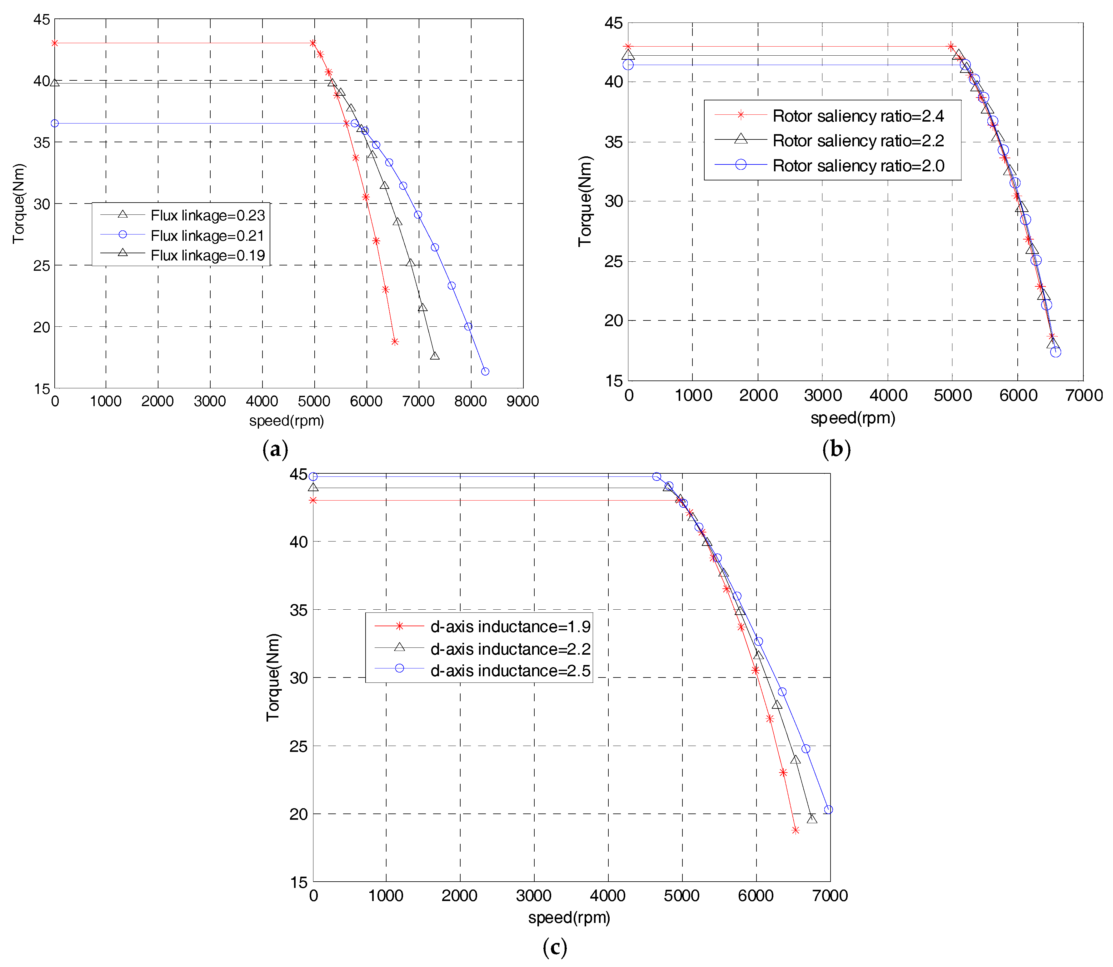
Figure 1a shows the effect of flux linkage provided by permanent magnets on the torque–speed characteristics. It is found that the small magnitude of magnet flux linkage signifies that there are some larger flux-weakening capability values, as well as some lower constant torque values. Figure 1b illustrates the torque–speed characteristics with constant permanent magnet flux linkage and-axis inductance, but a different rotor saliency ratio. It suggests that the rotor saliency ratio only increases the constant torque values, however it has no effect on constant power speed range. Figure 1c describes the effect of different d-axis inductance on the torque–speed characteristics; large d-axis inductance signifies a large constant torque value, and an extension of the constant power speed range.
2.2. Cogging Torque
The cogging torque is defined as a torque produced by magnetic forces in the circumferential direction between the stator teeth and the magnets of the rotor, which depend on the physical geometry of the stator teeth and the rotor magnets. For simplicity in the calculation of the air-gap field, the effect of slotting is ignored. The air-gap field produced by PMs in the slotless air gap is given by Equations (3) and (4)
where Brn and Btn are the radial and tangential components of the flux density amplitude, θs is the angle along the stator periphery, t is the time, p is the number of pole pairs, and ω is the rotor angular speed.
The influence of the stator slotting can be accounted for by introducing a complex relative air-gap permeance based on the simplification of the actual slot shape being replaced by an ideal parallel slot [21,22].
where λa and λb are the real and imaginary components of the relative complex air-gap permeance obtained by the conformal transformation and can be found in [22].
According to the Maxwell stress, the cogging torque of the motor can be expressed as
2.3. Torque Ripple
The armature reaction magnetic field with a smooth air gap is given by
where Bav and Btv are the radial and tangential components of the flux density amplitude. Thus, the radial and tangential field components of the load are obtained from the sum of the open-circuit and armature-reaction fields.
According to the Maxwell stress, the torque of the motor can be expressed as
When k ≠ 0, , for (np + υ) > 0, Equation (9) can be simplified as
Equation (13) shows that if and only if n = Sv, the torque is a constant value that does not change with time. When the current is sinusoidal, n = Sv = 1. Therefore, only the fundamental air gap magnetic field generates constant torque, while the other harmonics generate torque ripple.
2.4. Radial Force Model
According to the Maxwell stress, the radial force densities in the air gap can be expressed as:
When the air-gap magnetic field tangential component is small, the radial force densities can be approximated as:
where
where frr is the radical vibration force produced by the PM, frs is the radical vibration force produced by the PM and the armature-reaction field, and fss is the radical vibration force produced by the armature-reaction field.
3. Design and Optimization
Based on the proposed motor parameters listed in Table 1, an optimization is performed to further improve torque and minimize the torque ripple. Firstly, the finite element method (FEM) models of three motors with different rotor structures are established and solved. Secondly, the objective functions, constraints, and design variables are determined. Finally, using the GA, optimal points for the design variables are obtained.
3.1. FEM of Three Motors with Different Rotor Structures
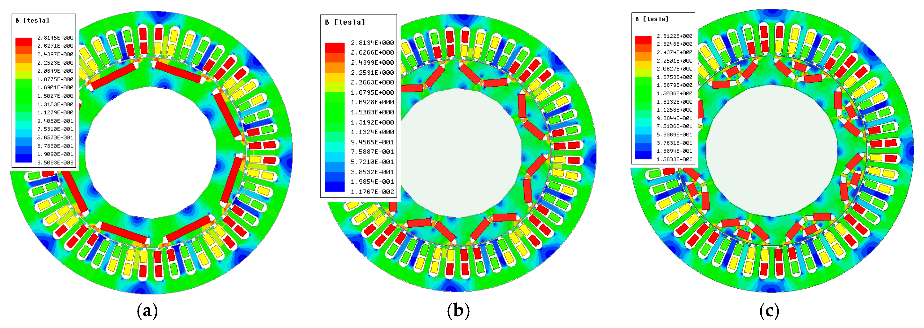
In this paper, Maxwell software is used for design optimization. The FEM values of the flat-type, V-type, and triangle-type motor are established and solved, with the same stator parameters, winding parameters, and permanent magnet volume. The magnetic flux density distributions are shown in Figure 2.
3.2. Objective Function, Constraints, and Design Variables
For multi-objective optimization problems, Non-dominated sorting genetic algorithm (NSGA)-II or NSGA-III is a good choice. However, the Maxwell finite element analysis software does not provide these two methods, nor does it provide other multi-objective optimization methods. Therefore, a method that attempts to convert multi-objective optimization into single-objective optimization is adopted in this paper. It is called the unified object method.
When all of the objective functions (1) – (m) are positive in the multi-objective optimization, the minimum values of functions (1) – (s) and the maximum values of functions (s) – (m) are expected, and the evaluation function can be used as follows:
Then, the following function is solved:
In this paper, we expect to obtain the minimum value of torque ripple Trip and the maximum value of average torque Tave. According to Equation (13), only the fundamental air-gap magnetic field generates constant torque, while the other harmonics generate torque ripple. The functions min (Trip) and max (Tave) mean that harmonics of air gap magnetic field are at a minimum and the fundamental wave is at a maximum. Therefore, the two functions are not conflicting. According to Equations (19) and (20), this multi-objective optimization problem can be translated into the single-objective optimization min (Trip/Tave).
The objective function, constraints, and design variables are shown in Table 2, where Tave is the average torque, Trip is the torque ripple, WM is the permanent magnet total width per pole, Rib is the width of ducts, Em is the pole embrace, and O2 and DM are distance from duct bottom to the shaft surface and the minimum distance between side magnets, respectively.
3.3. Optimization Results
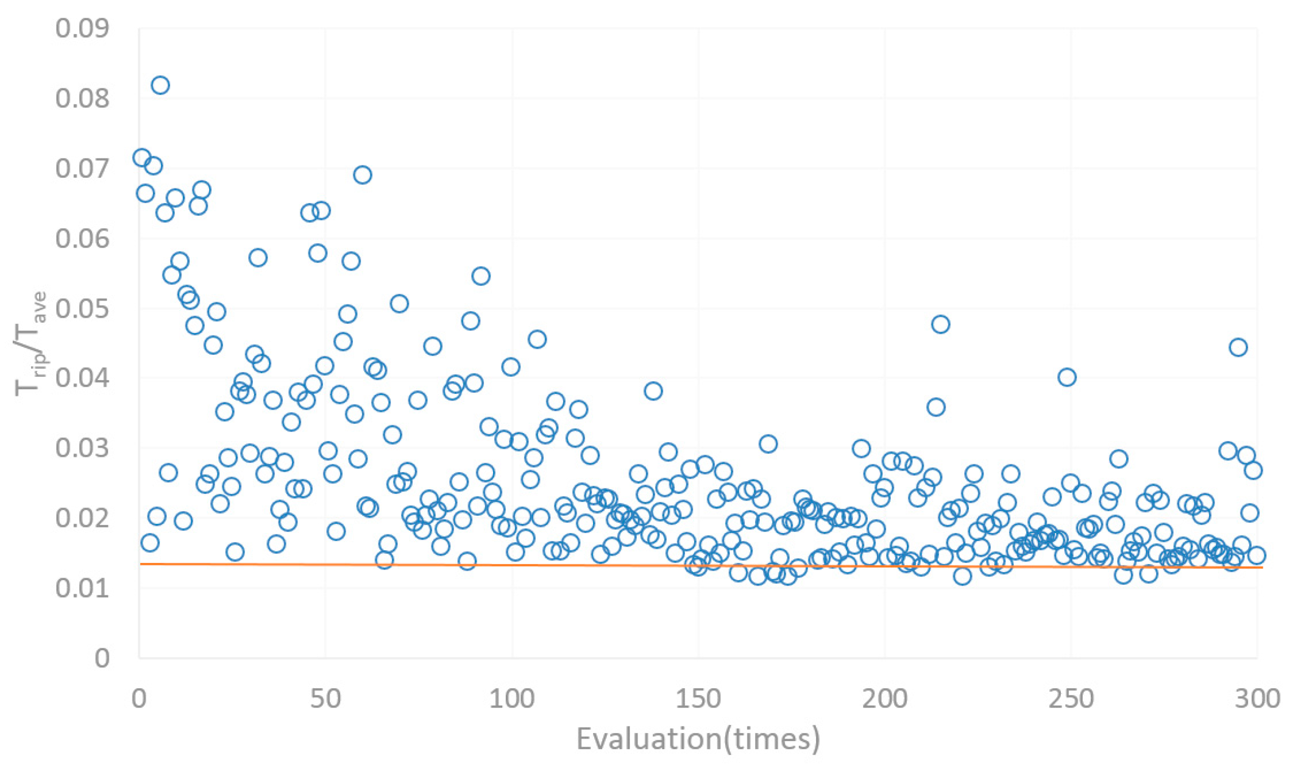
In this optimization, we cannot reach convergence to a single value. However, we can obtain a set of optimized values (shown below the red line in Figure 3), which represents small torque ripple Trip and large average torque Tave. These values are candidates for subjective evaluation. In this paper, the value with maximum average torque Tave is selected from the candidates as the optimization result. The design variables of un-optimized and optimized motors are listed in Table 3.
3.4. Proposed Slotted Rotor Configuration
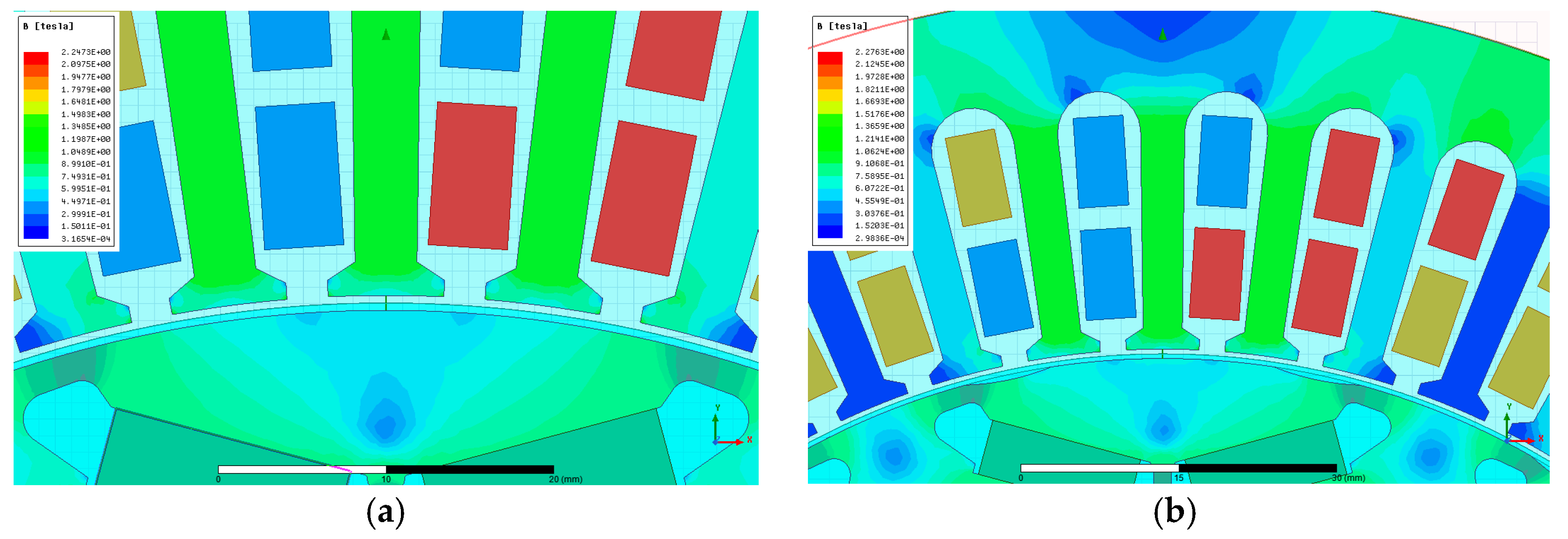
Figure 4 shows the configuration of the conventional rotor and proposed slotted rotor. As the outer shapes of the slotless rotor and proposed slotted rotor are different, the magnetic flux density distributions (amplitude and phase angle) are different. The torque ripple and radial vibration force can be reduced by suppressing the harmonic components of the radial magnetic flux density.
4. Results and Discussion
The detailed design parameters and procedures have been provided in Section 3, and hence the final design results are here compared and analyzed.
4.1. Comparisons of Torque Performance
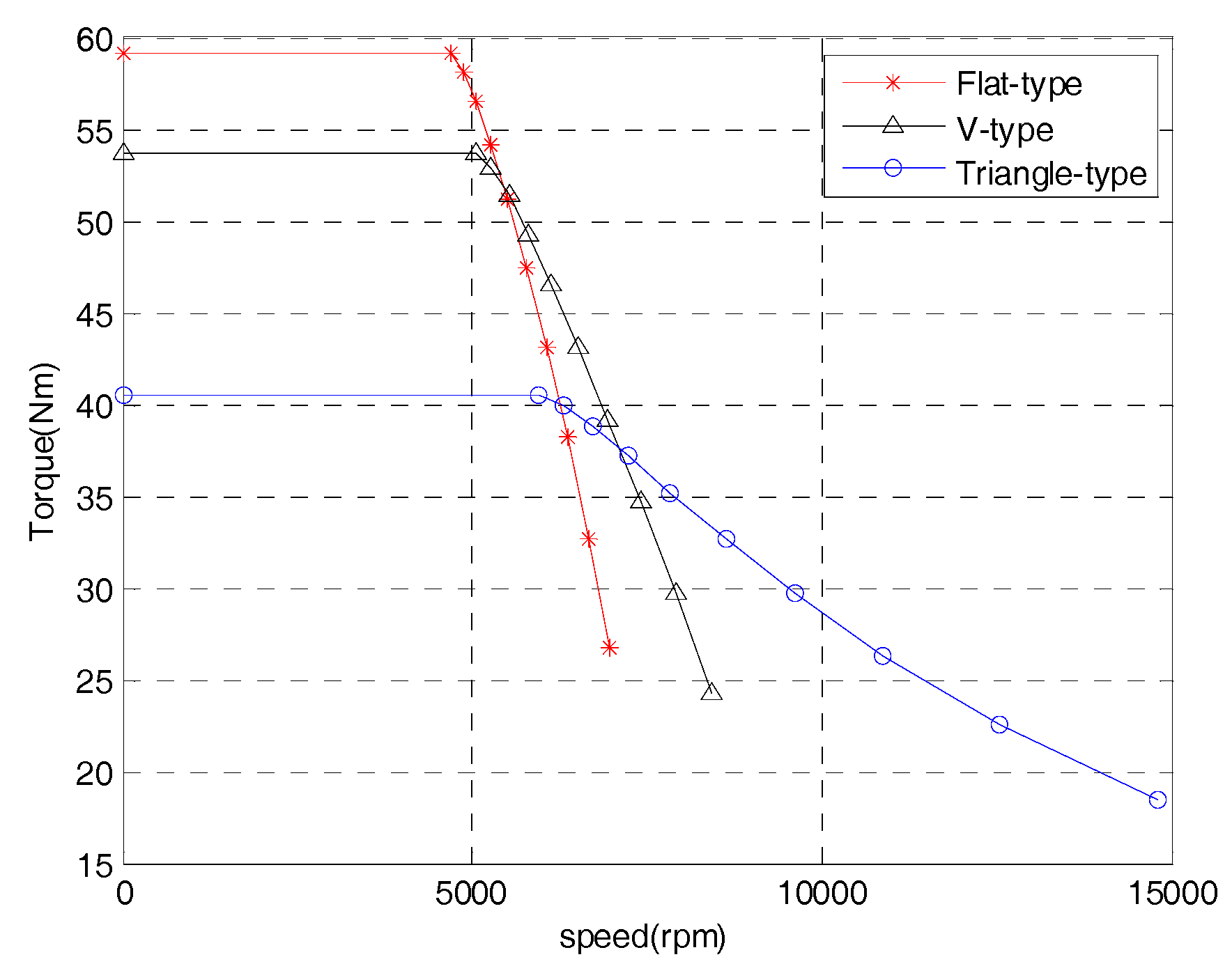
The comparisons of the flux linkage provided by permanent magnets, inductances, and the rotor saliency ratio when , are shown in Table 4. It can be seen that the triangle-type IPM motor has the lowest flux linkage and the highest d-axis inductance, which are important characteristics for wide-speed applications, as described in Section 2. Figure 5 demonstrates that the triangle-type IPM motor has the best extended speed performance.
4.2. Comparison of Core Loss and Eddy Current Loss
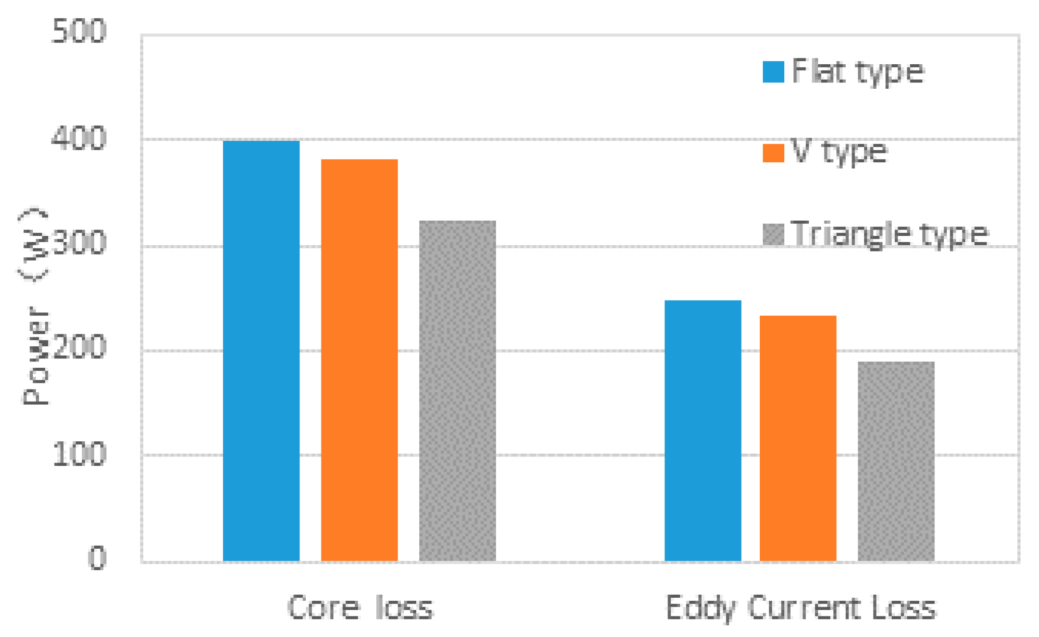
Figure 6 shows the core loss and eddy current loss of the three optimized motors. It can be observed that the triangle-type IPM motor has the lowest core loss and eddy current loss, while and .
4.3. Induced Voltage and Cogging Torque
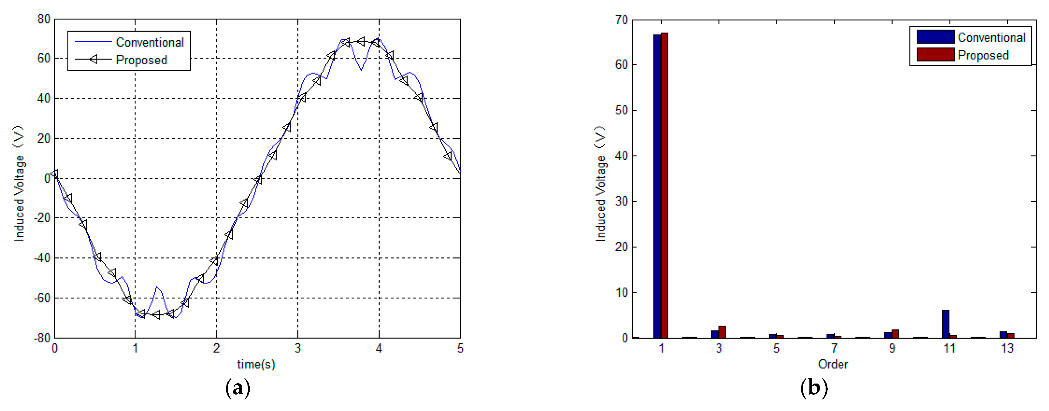
Figure 7 shows the comparison of the calculated values of the induced voltage on unloading. In the figure, part (a) shows the wave of the induced voltage and part (b) shows the results of harmonic analysis of induced voltage. It can be seen that the effective value of the fundamental wave is increased by approximately 0.7%, and the eleventh harmonic is clearly reduced.
The comparison of the calculated values of the cogging torque is shown in Figure 8. The cogging torque in the proposed motor is greatly increased.
4.4. Torque Ripple
Figure 9a shows the comparisons of the calculation results for the armature current with the control strategy of Maximum torque per ampere (MTPA). The effective value of the fundamental wave in a conventional motor is normalized as 100%. As can be seen from part (a) of Figure 9, the fundamental wave effective value of the armature current rose by approximately 1.5% in the proposed motor compared to the conventional motor. However, the effective value for the fundamental wave of induced voltage was reduced as shown in part (b) of Figure 9. Hence, when the output torques are same, the input power can be same or reduced in the proposed motor.
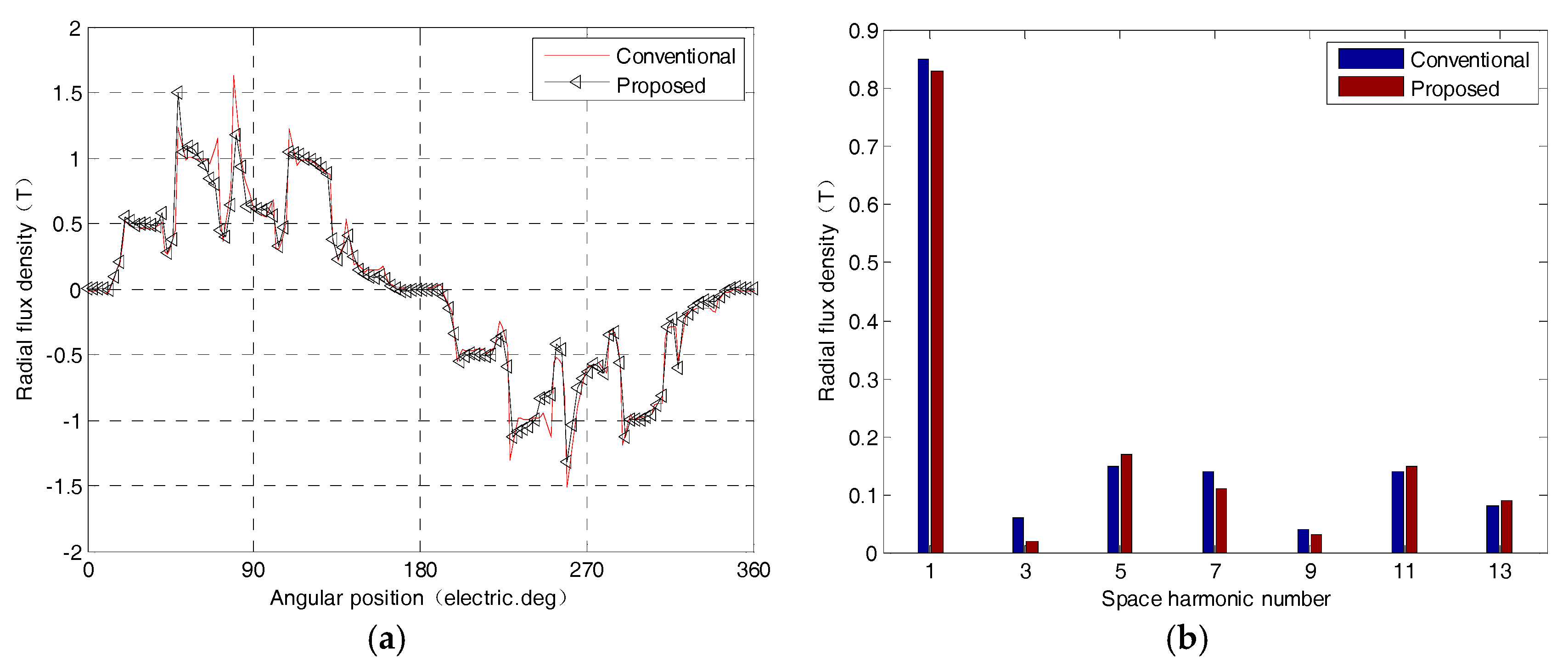
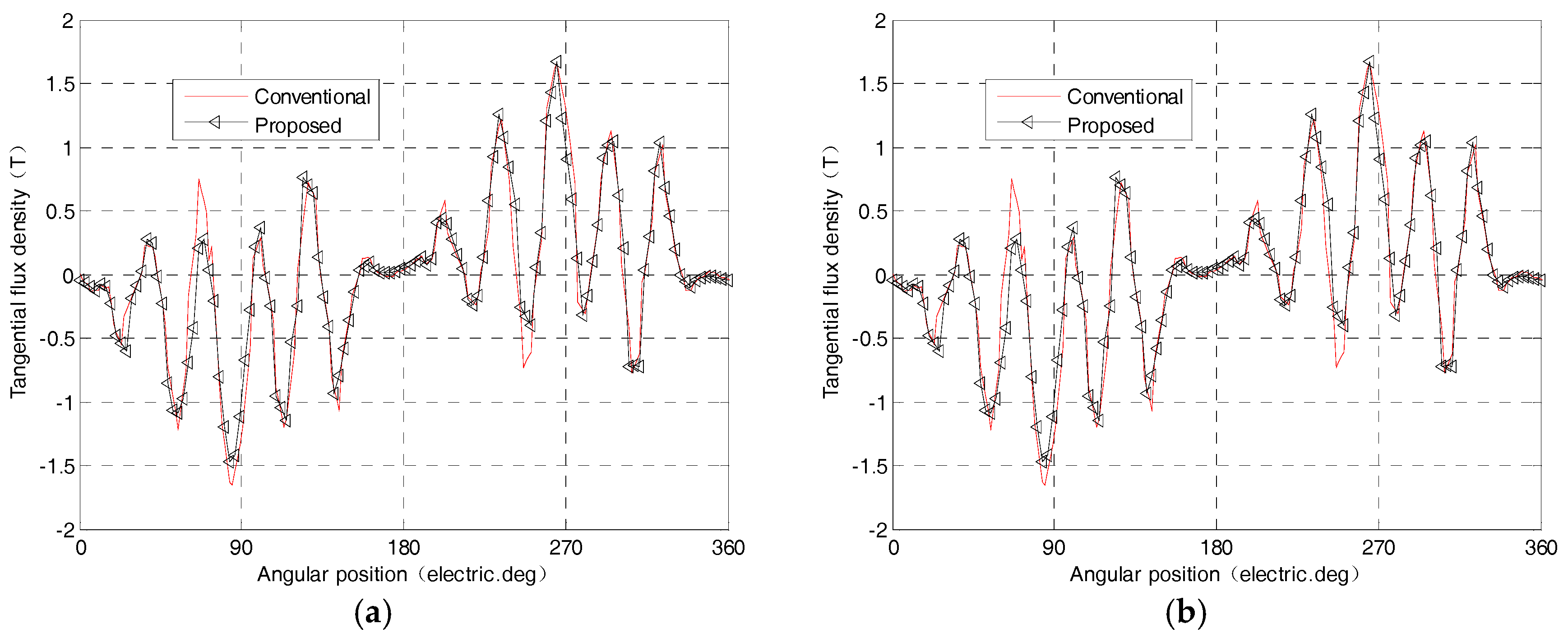
Figure 10 shows the calculation results for the harmonic spectrum of the radial–magnetic flux density observed in stator coordinates. Figure 11 shows the calculation results for the harmonic spectrum of the tangential–magnetic flux density observed in stator coordinates. It can be seen that the fundamental wave of radial magnetic flux density is smaller in the proposed machine. However, the fundamental wave of tangential magnetic flux density increased, and both radical harmonics and tangential harmonics of magnetic flux density are reduced.
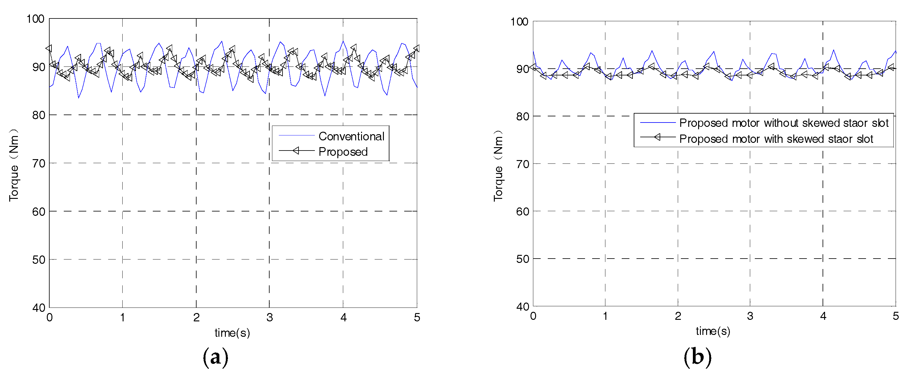
As can be seen from part (a) of Figure 12, the torque ripple is reduced in the proposed motor compared to the conventional motor, however the average torque can be same between conventional motor and the proposed motor. As shown in part (b) of Figure 12, the torque ripple is suppressed effectively by adopting a skewed stator slot.
4.5. Radical Electromagnetic Force
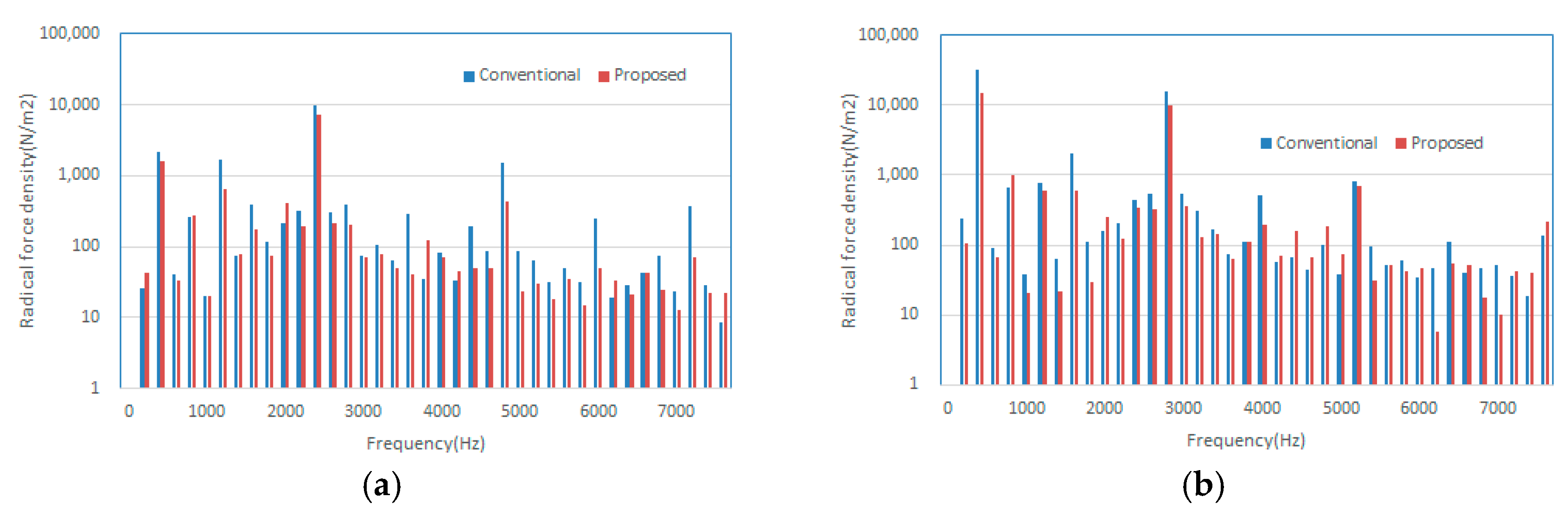
A comparison of the calculation results for the harmonic spectrum of the radial electromagnetic force is shown in Figure 13. It can be seen that the main radial electromagnetic forces of the zeroth order and eighth order in the proposed motor are reduced by between 0 and 8000 Hz, and are the main exciting forces of radial vibration of the 8-pole 48-slot motor.
5. Experiments and Verification
As shown in Figure 14, the proposed motor’s rotor with an auxiliary slot is fabricated to verify its effectiveness in suppressing vibration. The width of auxiliary slot is 3 mm. The main technical characteristics of the motor under testing are shown in Table 5.
Figure 15 shows a picture of the test bench used in the laboratory for these measurements. The motor under testing is on the right-hand side. The machine on the left-hand side is used as a brake. The results of induced voltage on unload are shown in Table 6. Simulation results and test results are consistent.
When we face the brake motor on the test motor side, the measuring point of vibration is arranged on the right side of the motor housing and the Z direction is the direction of motor axial. The results of vibration are shown in Table 7. The test results shows that the vibrations of the proposed motor are smaller than for the conventional motor.
6. Conclusions
This study focuses on optimizing the flux-weakening performance and reducing the vibration of IPM motor for EVs. Firstly, flux-weakening capability, cogging torque, torque ripple, and radical vibration force are analyzed based on the mathematical model. Secondly, three kinds of motors are optimized by the genetic algorithm and analyzed to provide visible insights into the contribution of different rotor structures to the torque characteristics, efficiency, and extended speed range. Thirdly, a slotted rotor configuration is proposed to reduce the torque ripple and radical vibration force. The flux density distributions are discussed in order to explain the principle that motor with the slotted rotor and skewed stator slot has smaller torque ripple and radical vibration force. Lastly, the design and optimization results have been validated against experiments. Conclusions can be drawn as follows:
- (1)
- The flat-type IPM has the highest constant torque, which may be a good choice for the low speed vehicle requiring a large torque value. The triangle-type IPM motor has the best extended speed performance and the lowest core loss and eddy current loss, perhaps representing a good choice for high-speed vehicles requiring high efficiency. The V-type IPM motor has good performance in both torque and extended speed performance.
- (2)
- By opening the auxiliary slot on the rotor of the drive motor, the harmonic content of the air-gap magnetic field can be optimized. The fundamental wave of radial flux density is smaller in the proposed machine, however the fundamental wave of tangential flux density is increased, and both radical harmonics and tangential harmonics of magnetic flux density are reduced. Thus, the motor output torque can remain unchanged while the torque pulsation is reduced, according to the Maxwell tensor equation.
- (3)
- The main radial electromagnetic forces of the zeroth order and eighth order in the proposed motor are reduced between 0 and 8000 Hz, and represent the main exciting force of radial vibration of the 8-pole 48-slot motor. The vibration is reduced, as verified by experimental results.
Author Contributions
Conceptualization, F.M. and H.Y.; Methodology, H.Y.; Software, L.W.; Validation, H.Y., G.T. and H.G.; Formal Analysis, L.W.; Investigation, H.Y.; Resources, H.G.; Data Curation, H.Y.; Writing-Original Draft Preparation, H.Y.; Writing-Review & Editing, H.Y.; Visualization, H.Y.; Supervision, F.M.; Project Administration, F.M.; Funding Acquisition, F.M. and G.T.
Funding
This research was funded by [National Science Foundation of China] grant number [51775238].
Acknowledgments
Authors’ special thanks go to Hongli Zhang, Bin Zhang and Wenpeng Ma for their support and the fruitful technical discussions.
Conflicts of Interest
The author declares no conflict of interest. The founding sponsors had no role in the design of the study; in the collection, analyses, or interpretation of data; in the writing of the manuscript, and in the decision to publish the results.
References
- Iodice, P.; Senatore, A. Atmospheric pollution from point and diffuse sources in a National Interest Priority Site located in Italy. Energy Environ. 2016, 27, 586–596. [Google Scholar] [CrossRef]
- Iodice, P.; Prati, M.; Meccariello, G.; Prati, M.V. Methodology for the analysis of a 4-stroke moped emission behaviour. SAE Int. J. Engines 2009, 2, 617–626, 2009-24-0142. [Google Scholar] [CrossRef]
- Garg, A.; Vijayaraghavan, V.; Zhang, J.; Lam, J.S.L. Robust model design for evaluation of power characteristics of the cleaner energy system. Renew. Energy 2017, 112, 302–313. [Google Scholar] [CrossRef]
- Garg, A.; Vijayaraghavan, V.; Zhang, J.; Li, S.; Liang, X. Design of robust battery capacity model for electric vehicle by incorporation of uncertainties. Int. J. Energy Res. 2017, 41, 1436–1451. [Google Scholar] [CrossRef]
- Cao, R.; Mi, C.; Cheng, M. Quantitative Comparison of Flux-Switching Permanent-Magnet Motors with Interior Permanent Magnet Motor for EV, HEV, and PHEV Applications. IEEE Trans. Magn. 2012, 48, 2374–2384. [Google Scholar] [CrossRef]
- Park, E.; Lim, J.; Cho, Y. Migrating towards Using Electric Vehicles in Campus-Proposed Methods for Fleet Optimization. Sustainability 2018, 10, 285. [Google Scholar] [CrossRef]
- Park, E.; Lim, J.; Cho, Y. Understanding the Emergence and Social Acceptance of Electric Vehicles as Next-Generation Models for the Automobile Industry. Sustainability 2018, 10, 662. [Google Scholar] [CrossRef]
- Liu, X.; Chen, H.; Zhao, J.; Belahcen, A. Research on the Performances and Parameters of Interior PMSM Used for Electric Vehicles. IEEE Trans. Ind. Electron. 2016, 63, 3533–3545. [Google Scholar] [CrossRef]
- Laskaris, K.I.; Kladas, A.G. Internal Permanent Magnet Motor Design for Electric Vehicle Drive. IEEE Trans. Ind. Electron. 2010, 57, 138–145. [Google Scholar] [CrossRef]
- Hsu, J.S. Report on Toyota/Prius Motor Design and Manufacturing Assessment; Oak Ridge National Laboratory (ORNL): Oak Ridge, TN, USA, 2004. [Google Scholar]
- Burress, T.A.; Campbell, S.L.; Coomer, C.; Ayers, C.W.; Wereszczak, A.A.; Cunningham, J.P.; Marlino, L.D.; Seiber, L.E.; Lin, H.-T. Evaluation of the 2010 Toyota Prius Hybrid Synergy Drive System; Technical Reports; Office of Scientific & Technical Information: Oak Ridge, TN, USA, 2011. [Google Scholar]
- Taniguchi, M.; Yashiro, T.; Takizawa, K.; Baba, S.; Tsuchida, M.; Mizutani, T.; Endo, H.; Kimura, H. Development of New Hybrid Transaxle for Compact-Class Vehicles. In Proceedings of the SAE 2016 World Congress and Exhibition, Detroit, MI, USA, 12–14 April 2016; pp. 742–749. [Google Scholar]
- Liu, G.; Xu, G.; Zhao, W.; Du, X.; Chen, Q. Improvement of Torque Capability of Permanent-Magnet Motor by Using Hybrid Rotor Configuration. IEEE Trans. Energy Convers. 2017, 32, 953–962. [Google Scholar] [CrossRef]
- Bianchi, N.; Alberti, L.; Barcaro, M. Design and Tests of a Four-Layer Fractional-Slot Interior Permanent-Magnet Motor. IEEE Trans. Ind. Appl. 2016, 52, 2234–2240. [Google Scholar] [CrossRef]
- Zhao, W.; Zhao, F.; Lipo, T.A.; Kwon, B.I. Optimal Design of a Novel V-Type Interior Permanent Magnet Motor with Assisted Barriers for the Improvement of Torque Characteristics. IEEE Trans. Magn. 2014, 50, 1–4. [Google Scholar] [CrossRef]
- Sanada, M.; Hiramoto, K.; Morimoto, S.; Takeda, Y. Torque ripple improvement for synchronous reluctance motor using an asymmetric flux barrier arrangement. IEEE Trans. Ind. Appl. 2004, 40, 1076–1082. [Google Scholar] [CrossRef]
- Ionel, D.M.; Popescu, M.; McGilp, M.I.; Miller, T.J.E.; Dellinger, S.J. Assessment of torque components in brushless permanent-magnet machines through numerical analysis of the electromagnetic field. IEEE Trans. Ind. Appl. 2005, 41, 1149–1158. [Google Scholar] [CrossRef]
- Parsa, L.; Hao, L. Interior Permanent Magnet Motors with Reduced Torque Pulsation. IEEE Trans. Ind. Electron. 2008, 55, 602–609. [Google Scholar] [CrossRef]
- Jahns, T.M.; Soong, W.L. Pulsating torque minimization techniques for permanent magnet AC motor drives—A review. IEEE Trans. Ind. Electron. 1996, 43, 321–330. [Google Scholar] [CrossRef]
- Zarko, D. A Systematic Approach to Optimized Design of Permanent Magnet Motors with Reduced Torque Pulsations. Master’s Thesis, University of Wisconsin-Madison, USA-Wisconsin, Madison, WI, USA, 2004. [Google Scholar]
- Zhu, Z.Q.; Xia, Z.P.; Wu, L.J.; Jewell, G.W. Analytical Modeling and Finite-Element Computation of Radial Vibration Force in Fractional-Slot Permanent-Magnet Brushless Machines. IEEE Trans. Ind. Appl. 2010, 46, 1908–1918. [Google Scholar] [CrossRef]
- Zarko, D.; Ban, D.; Lipo, T.A. Analytical calculation of magnetic field distribution in the slotted air gap of a surface permanent-magnet motor using complex relative air-gap permeance. IEEE Trans. Magn. 2006, 42, 1828–1837. [Google Scholar] [CrossRef]
Figure 1.
Torque–speed characteristics. (a) and ; (b) and ; (c) and .

Figure 2.
The magnetic field distribution of the proposed motors. (a) Flat-type; (b) V-type; (c) Triangle-type.
Figure 2.
The magnetic field distribution of the proposed motors. (a) Flat-type; (b) V-type; (c) Triangle-type.

Figure 3.
Optimal results using the genetic algorithm (GA).

Figure 4.
Configuration of the conventional rotor and proposed slotted rotor. (a) Conventional rotor; (b) proposed slotted rotor.
Figure 4.
Configuration of the conventional rotor and proposed slotted rotor. (a) Conventional rotor; (b) proposed slotted rotor.

Figure 5.
Comparative study of torque–speed characteristics.

Figure 6.
Comparison of core loss and eddy current loss.

Figure 7.
Comparison of the calculation results for induced voltage. (a) Wave of the induced voltage; (b) Harmonic analysis of the induced voltage.
Figure 7.
Comparison of the calculation results for induced voltage. (a) Wave of the induced voltage; (b) Harmonic analysis of the induced voltage.

Figure 8.
The comparison of the calculation results for cogging torque.

Figure 9.
The comparisons of the calculation results for armature current and induced voltage (a) Comparison of current amplitude; (b) Comparison of induced voltage.
Figure 9.
The comparisons of the calculation results for armature current and induced voltage (a) Comparison of current amplitude; (b) Comparison of induced voltage.

Figure 10.
The comparison of the calculation results for the harmonic spectrum of radial magnetic flux density in tooth tips. (a) Comparison of radial flux density; (b) The fast fourier transform (FFT) of the radial flux density.
Figure 10.
The comparison of the calculation results for the harmonic spectrum of radial magnetic flux density in tooth tips. (a) Comparison of radial flux density; (b) The fast fourier transform (FFT) of the radial flux density.

Figure 11.
The comparison of the calculation results for the harmonic spectrum of tangential magnetic flux density. (a) Comparison of tangential flux density; (b) The fast fourier transform (FFT) of the tangential flux density.
Figure 11.
The comparison of the calculation results for the harmonic spectrum of tangential magnetic flux density. (a) Comparison of tangential flux density; (b) The fast fourier transform (FFT) of the tangential flux density.

Figure 12.
Calculation results for torque. (a) Comparison of the conventional and proposed motor torque; (b) Comparison of proposed motor with a skew slot and without a skew slot.
Figure 12.
Calculation results for torque. (a) Comparison of the conventional and proposed motor torque; (b) Comparison of proposed motor with a skew slot and without a skew slot.

Figure 13.
Comparison of calculation results for spectrum harmonic of radical electromagnetic force. (a) Zeroth order; (b) Eighth order.
Figure 13.
Comparison of calculation results for spectrum harmonic of radical electromagnetic force. (a) Zeroth order; (b) Eighth order.

Figure 14.
The proposed motor.

Figure 15.
Test bench for the motor test.


Table 1.
Parameters of the proposed motors.
| Items | Unit | Value |
|---|---|---|
| Number of stator slot | - | 48 |
| Number of rotor pole | - | 8 |
| Stator outer diameter (mm) | mm | 214 |
| Stator inner diameter (mm) | mm | 145 |
| Air gap length (mm) | mm | 0.9 |
| Rotor outer diameter (mm) | mm | 143.2 |
| Rotor inner diameter (mm) | mm | 100 |
| Total PM volume (mm3) | cm3 | 1628 |
| Iron core material | - | DW540_50 |
| PM material | - | N35 |
| Remanence of PM (T) | T | 1.23 |
| Coercive force of PM (kA/m) | kA/m | −890 |
Table 2.
Objective Function, Constraints, and Design Variables.
| Items | Flat-Type | V-Type | Triangle-Type |
|---|---|---|---|
| Objective Function | Minimize Trip/Tave | ||
| Constraints | 100 ≤ β ≤ 130 | ||
| Design Variables | 30 ≤ WM ≤ 37 | ||
| 32 ≤ WM ≤ 37 | 4.0 ≤ O2 ≤ 5.5 | ||
| 32 ≤ WM ≤ 37 | 4.0 ≤ O2 ≤ 5.5 | 9.5 ≤ Rib ≤ 12 | |
| 9.5 ≤ Rib ≤ 12 | 9.5 ≤ Rib ≤ 12 | 5 ≤ DM ≤ 10 | |
| 0.70 ≤ Em ≤ 0.75 | 2 ≤ DM ≤ 3 | 38.5 ≤ Rib2 ≤ 38.8 | |
Table 3.
The design variables of the un-optimized and optimized motors.
| Items | Flat-Type | V-Type | Triangle-Type | |||
|---|---|---|---|---|---|---|
| Un-Optimized | Optimized | Un-Optimized | Optimized | Un-Optimized | Optimized | |
| Total width of permanent magnet | 37 | 36.9 | 37 | 36.8 | 37 | 35 |
| Pole embrace | 0.7 | 0.7 | - | - | - | - |
| Distance from duct bottom to shaft surface | - | - | 5.5 | 5.2 | 5.5 | 4.3 |
| Width of ducts 1 | 10 | 9.5 | 9.5 | 9.8 | 10 | 10.4 |
| Width of ducts 2 | - | - | - | - | 38 | 38.7 |
| Minimum distance between side magnets | - | - | 3 | 2.25 | 8.0 | 6.9 |
Table 4.
Comparative analysis of motor parameters in the IPM motor designs.
| Items | Flat-Type | V-Type | Triangle-Type |
|---|---|---|---|
| Magnet volume (mm3) | 1628 | 1628 | 1628 |
| Flux linkage(Weber) | 0.2273 | 0.2069 | 0.1544 |
| d-axis inductance (mH) | 1.7740 | 2.1098 | 2.8028 |
| q-axis inductance (mH) | 4.3988 | 4.4852 | 4.6686 |
| Rotor saliency ratio | 2.48 | 2.13 | 1.67 |
Table 5.
Main technical characteristics of the motor under testing.
| Items | Unit | Value |
|---|---|---|
| DC voltage range | V | 265~410 |
| Peak power | kW | 65 |
| Continuous power | kW | 28 |
| Number of stator slot | - | 48 |
| Number of rotor pole | - | 8 |
| Rated speed | rpm | 2600 |
| Stack length (mm) | mm | 136 |
| Stator outer diameter (mm) | mm | 214 |
| Stator inner diameter (mm) | mm | 145 |
| Air-gap length (mm) | mm | 0.9 |
| Rotor outer diameter (mm) | mm | 143.2 |
Table 6.
Results of induced voltage on unloading.
| Item | Rotate Speed (rpm) | Electrical Frequency (Hz) | Line Voltage Amplitude (mV) |
|---|---|---|---|
| 01 | 2500 | 33.34 | 198 |
| 02 | 1000 | 66.67 | 384 |
| 03 | 2000 | 133.6 | 770 |
| 04 | 2600 | 173.3 Hz | 1001 |
Table 7.
Test results of vibration.
| Test Conditions | Direction | Vibration Acceleration (g) | |
|---|---|---|---|
| Conventional Motor | Proposed Motor | ||
| 25% load 2000 rpm | X | 0.10 | 0.05 |
| Y | 0.08 | 0.04 | |
| Z | 0.17 | 0.03 | |
| 25% load 7000 rpm | X | 0.54 | 0.47 |
| Y | 0.79 | 0.73 | |
| Z | 1.16 | 0.51 | |
© 2018 by the authors. Licensee MDPI, Basel, Switzerland. This article is an open access article distributed under the terms and conditions of the Creative Commons Attribution (CC BY) license (http://creativecommons.org/licenses/by/4.0/).
Share and Cite
MDPI and ACS Style
Ma, F.; Yin, H.; Wei, L.; Tian, G.; Gao, H. Design and Optimization of IPM Motor Considering Flux Weakening Capability and Vibration for Electric Vehicle Applications. Sustainability 2018, 10, 1533. https://doi.org/10.3390/su10051533
AMA Style
Ma F, Yin H, Wei L, Tian G, Gao H. Design and Optimization of IPM Motor Considering Flux Weakening Capability and Vibration for Electric Vehicle Applications. Sustainability. 2018; 10(5):1533. https://doi.org/10.3390/su10051533
Chicago/Turabian StyleMa, Fangwu, Hongbin Yin, Lulu Wei, Guangdong Tian, and Hui Gao. 2018. "Design and Optimization of IPM Motor Considering Flux Weakening Capability and Vibration for Electric Vehicle Applications" Sustainability 10, no. 5: 1533. https://doi.org/10.3390/su10051533
Note that from the first issue of 2016, this journal uses article numbers instead of page numbers. See further details here.