Article

Active Power Management of Virtual Power Plant under Penetration of Central Receiver Solar Thermal-Wind Using Butterfly Optimization Technique

1
Department of Electrical Engineering, National Institute of Technology Silchar, Assam 788010, India
2
Fukushima Renewable Energy Institute, AIST (FERA), National Institute of Advanced Industrial Science and Technology (AIST), Koriyama 963-0298, Japan
*
Author to whom correspondence should be addressed.
Sustainability 2020, 12(17), 6979; https://doi.org/10.3390/su12176979
Submission received: 15 July 2020 / Revised: 24 August 2020 / Accepted: 25 August 2020 / Published: 27 August 2020
(This article belongs to the Special Issue Photovoltaic Power)

Abstract

:
Striving for the suppression of greenhouse emissions, the modern power network is facing fundamental changes with the utilization of renewable energies (REs) for the future carbon-free society. The utilization of intermittent renewable-green power needs a better power management system and virtual power plant (VPP) can be a vital candidate that meets this demand. This study investigates a coordinated control grid integrated virtual power plant (VPP) in the presence of Central Receiver Solar Thermal System (CRSTS), Wind Turbine Generator (WTG), and Electric Vehicle (EV). To this end, CRSTS employed with thermal storage acts as a dispatchable renewable generating unit and coordinated control of the system units are achieved using the available control strategy on interconnected microgrids in the modified form, employing communication time delay. The proposed control strategy employs the proportional-integral (PI) and PI-derivative (PID) controller. Coordinated power control with real-time communication delay in grid integrated VPP in presence of CRSTS, WTG, and EV is a novel approach. Genetic algorithm (GA), Particle Swarm Optimization (PSO), Slap Swarm Algorithm (SSA), and recent Butterfly Optimization Algorithm (BOA) are used for tuning the necessary control parameters. The results establish the superiority of the BOA over SSA and PSO in suppressing system frequency deviations and tie line power deviation. The analysis of the dynamic response reveals that the consideration of the communication delay in the system expressively impedes the stable operation of the power system.

1. Introduction

Recent developments in power systems have led to more complex dynamic networks and have radically revolutionized the very concept of the conventional power system. In particular, the increased deployment of renewable energy (RE) sources and higher propagation of prosumers [1] into electricity networks are encouraged for curbing global warming and reducing fossil fuel use. However, due to certain socio-technical drawbacks and intermittent nature of RE sources, their integration creates issues in power system operation. Maintaining power quality, ensuring reliability and stability become a challenging task. As a solution, several RE units aggregated as a single entity have emerged as a conventional generating unit that can make the job easier. Such aggregation is called virtual power plant (VPP). Although there is no comprehensive definition and definite structure of a VPP, there are some general conceptual designs. It is a cluster of distributed energy resources (DERs), storage units, controllable or flexible loads that together operate as a conventional generator [2]. The electric vehicle (EV) is one of the storage devices which can act as a controllable load also.
Meanwhile, it has been projected that the worldwide energy demand would increase to 1.5 times the present value by 2030 [3]. Further, most of the countries are bound to cut CO2 emissions so as to arrest the global average temperature increase below 2 °C, as per the Paris agreement [4]. In order to meet the above two challenges, a major portion of the world energy requirements should be supplied by RE sources. Amongst the available RE sources, like wind energy systems, the central receiver solar thermal system (CRSTS) is also promising technology that has the potential to provide significant dispatchable power. Especially during a cloudy day or night time, the thermal storage capability makes the system available for generation [5]. The presence of thermal storage absorbs the intermittent nature of output power generation. Further, because of its capability to operate at high temperature and lesser land requirements as compared to other technologies, CRTS has gained much popularity. These benefits of CRSTS make it a carbon-free and sustainable energy solution. The state of the art of CRSTS technology has been discussed in [6]. Although the cost of this concentrated solar thermal power at present is costlier than that of other renewable technology, with significant technological development and large-scale generation, the generation cost of this technology is expected to be on par with the thermal generation [5]. To this end, several countries are working towards development of this technology that would make CRSTS a vital candidate for VPP application.
VPP is supported by information and communication technology (ICT) [7], and improves stability, reliability, and resiliency by tailoring the plethora of RE sources spreading over the geographical areas, while providing other benefits [8,9]. For instance, through proper coordination of the RE sources, storage capacity, and controllable loads, VPP may ensure stable operation and peak load reduction. Additionally, VPP allows market participation for prosumers, and provides auxiliary services [10]. In ancillary service, voltage and load-frequency control are two important strategies that are essential in maintaining power system stability [11]. Although VPPs are likely to play a vital task in future energy systems through the aggregation of DERs and storage devices, developing control strategies for proper operation is a challenging task [12]. This is because of the integration of RE sources which are stochastic in nature due change in the weather conditions. The output power variations of RE sources give rise to imbalance between the power generation (active and reactive) and load demand, which result in frequency and voltage fluctuations.
A conventional power system with high inertia is of bulk capacity; integration of RE sources or EV in such a power system may not create much fluctuation in frequency. While a microgrid with low capacity has less system inertia, when such a microgrid is integrated with RE sources or EV, the output power fluctuation may crease the system frequency fluctuation. However, integrating the microgrid with the VPP architecture may resolve this issue to some extent. Nevertheless, the control concept strategy of VPP demands much attention.
Recent works on VPP [13,14,15,16,17,18,19] emphasize the requirement of frequency regulation in power system networks with high penetration of renewable sources or DERs. A VPP with a robust and efficient energy management system (EMS) has the potential to address this need [13]. VPP allows dynamic participation of DER, prosumers, and energy storage system (ESS) to maintain the demand-supply balance of the grid at different time scales [14,15]. Necessary market participation steps were studied in [16,17]. Hierarchical control strategies and coordinated EMS algorithm for generation command dispatch amongst the VPP participants towards system frequency stabilization were studied in [18]. VPP was reported to use some optimization tools and controller design for containment of frequency fluctuation in the electrical power system [19]. Authors in [20] focused on direct load control approach for consumers to participate in VPP-based electricity markets. In [21], authors presented Hybrid Automata (HA) for modeling of VPP with a conceptual control strategy in the presence of combined heat and power (CHP), battery, wind, and solar photovoltaic (PV). Although certain literature has reported RE-based VPP control strategies, there is still ongoing research to develop a mature control structure similar to those in conventional power system. It has been stated that VPPs are usually operated in grid-connected mode, as the isolated operation may not be feasible. Controlling DERs in VPP is akin to the secondary control approach of microgrids that takes comparatively higher time for control action as compared to primary control strategy [18]. Therefore, VPP can make use of ICT that causes certain time delay. These communication delays play a significant role in VPP design, operation, and analysis, as longer delays could be detrimental to the power system’s health [22]. Therefore, in the context of VPPs, communication delay needs to be set appropriately by finding the time-lag required before regulatory action is introduced to contain the power imbalance and oscillations.
Meanwhile, optimization techniques and control strategies for microgrid/interconnected have also attracted research attention. Several optimization techniques, such as genetic algorithmic technique (GA) [18,23], Particle Swarm Algorithmic technique (PSO) [24], and social spider algorithmic technique (SSA) [25] have been researched to this end. Recently, butterfly optimization algorithm (BOA) was reported to provide a better solution in solving several complex engineering problems compared to other metaheuristic algorithms [26]. Therefore, the performance of the BOA may be explored in providing better tuning of controllers’ parameters and hence better frequency regulation of the VPP model.
Recent research on control strategies for interconnected microgrids has been reported in [27,28,29]. In [27], the authors considered the fmincon solver method, a Matlab function and compared the performance with the proportional–integral–derivative (PID) based control strategy. The grasshopper optimization technique-fuzzy PID-based control strategy [28] and comparative performance of social-spider tuned PID control strategy vis-a-vis GA tuned PID control strategy were investigated in [29]. GA, PSO, sine-cosine algorithm, and Grasshopper optimization algorithm tuned PID control strategy were researched in [30]. The communication delay is significant for the realization of such interconnected microgrid system operation, because when this delay exceeds a threshold value, the microgrid may oscillate and may lose stability [31]. Therefore, for better realization of interconnected microgrids, communication delay (time required for receiving and sending information between the control center and the devices) should have been incorporated.
In light of the above, the present work develops a control strategy for VPPs based on control strategy of an interconnected microgrid [31]. The major contributions of this research work are:
(a)
The development of grid-integrated VPP in the presence of CRSTS, WTG, and EV and implementing it in MATLAB Simulation platform;
(b)
The application of available control strategy on interconnected microgrid in modified form for active power regulation of VPP model;
(c)
Considering communication delay in control system design and evaluations;
(d)
Use of a recent meta-heuristic optimization tool, namely BOA, for optimizing the control parameters and comparing the performance with GA, PSO, and SSA.

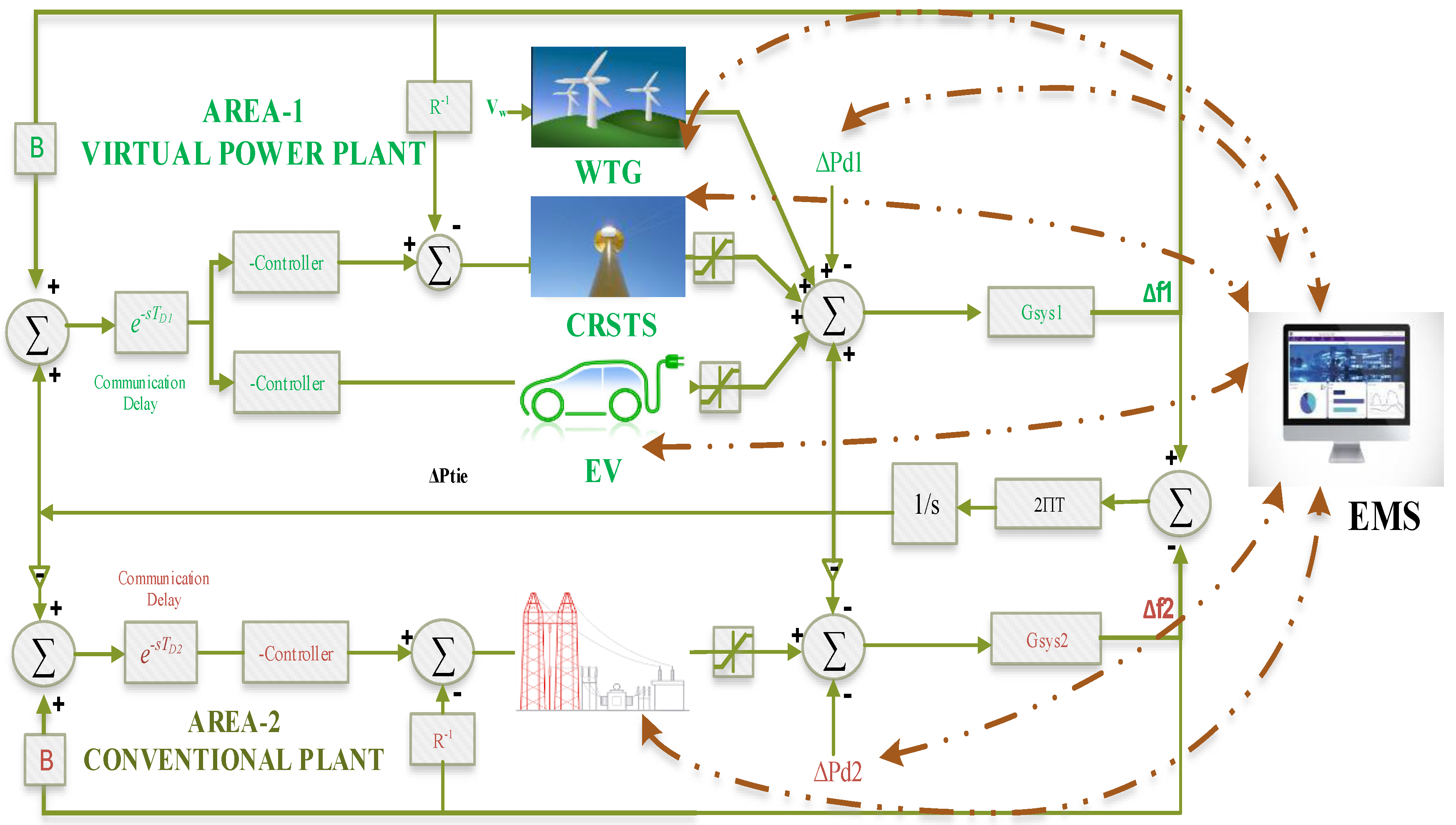
2. DER Modeling in VPP

The schematic structure of CRSTS is displayed in Figure 1. VPP design is illustrated in Figure 2, where DERs such as CRSTS, EV, and WTG are considered as Area-1 and a large conventional non-reheat turbine is considered as Area-2. The system components with respective mathematical models are illustrated below. The nomenclatures with values of some design parameters considered in this work are listed in Table 1.

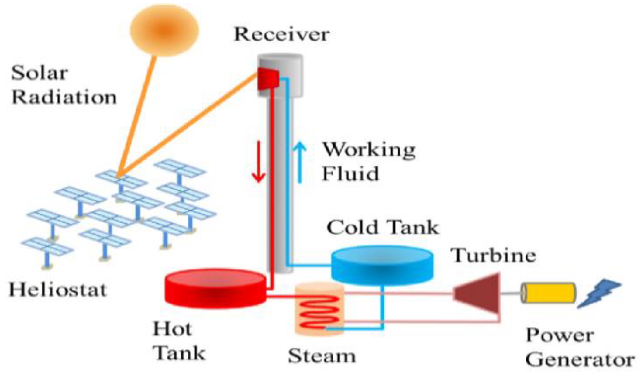
2.1. Central Receiver Solar Thermal System (CRSTS)

CRSTS is one of the most appropriate DER types for VPP due to its potential and thermal storage capability. In particular, thermal energy storage capability responds to power demand fluctuations while leveling the output variation due to stochastic nature of solar energy. CRSTS’s thermal electricity conversion efficiency is about 28% [32]. Worldwide, there are around 35 CRSTS projects in operation [3], with capacities in the order of MWs. Figure 1 shows the schematic diagram of a CRSTS.
CRSTS converts sunshine to electricity. It operates by concentrating the solar rays to a central receiver using heliostats. A heat transfer fluid is heated and stored in storage tanks. As per the demand, the stored thermal energy is used to produce steam, which drives the turbine generator to produce clean energy. In the proposed work, the CRSTS is considered as a dispatchable power generator. The transfer function model of CRSTS is [34]:
G C R S T S ( S ) = ( K R F 1 + s T R F ) ( K R V 1 + s T R V ) ( K G 1 + s T G ) ( K T 1 + s T T ) ,
where KRF, KRV, KG, KT represent the gain of the refocus, receiver, governor, and turbine of CRSTS, respectively. The TRF, TRV, TG, TT are the time constants of refocus, receiver, governor, and turbine of CRSTS.

2.2. Wind Turbine Generator (WTG)

The wind turbine unit is one of the fasted growing renewable energy technologies. Nowadays, wind power has become the most important part of modern energy supply because of its capacity and availability. Energy conversion from wind to electricity is done by a wind turbine system, which includes a rotor with blades, gearbox, electrical generator, and power electronics component. The power output of the wind turbine depends on the speed of wind at that instant. Wind turbines contain several nonlinearities, so while modeling this must be considered. The wind turbine model is simplified into a first order system. The transfer function of WTG based on modeling in [23] is expressed by following equation:
G W T G ( s ) = K W T G T W T G s + 1 ,
where KWTG, TWTG are the gain and time constant of WTG.

2.3. Electric Vehicle (EV)

The electric vehicle is the most promising technology that provides s solution to the environmental issues by reducing CO2 emissions [35,36], and at the same time minimizes the use of oil on a per kilometer basis. EVs can work as an energy storing device to absorb renewable energy and provide support to grid service when it is plugged-in. The bidirectional connection capability of converters in EVs’ structure has made them a secure backup for frequency support in power systems. The model which is used in this paper is the first order system. The transfer function model of EV based on modeling in [37] is expressed by the following equation:
G E V ( s ) = 1 T T d s + 1 ,
where TTd is the time constant of EV.

2.4. Conventional Synchronous Generator

The non-reheat turbine is one of the proficient and flexible machines which are capable of fulfilling a wide range of steam cycle applications. In this paper, the conventional plant used is not a reheat turbine type and the non-reheat turbine consists of three parts and their transfer function models are:
Governor with Dynamics:
G g ( s ) = 1 T G 1 s + 1 ;
Turbines with Dynamics:
G t ( s ) = 1 T T 1 s + 1 ;
Load and Machine Dynamics:
G p ( s ) = K P T P s + 1 ;
where TRF, TRV represent the time constant of conventional generator and turbine, and the overall conventional system’s gain and time constant are depicted by KP and TP.

2.5. Information and Communication Technology (ICT)

Future VPPs would connect millions of prosumers, DERs including RES, energy-storing devices, and a plethora of energy-consuming appliances. It would essentially allow two-way communication for receiving and sending information regarding running status, energy management, analysis, conveying control signals to all the VPP system components. This could only be achieved by profound application of information and communication technologies (ICT). Hence, it is highly likely that ICT would become one of the most essential VPP research topics. ICT such as internet of things or cloud-based infrastructure are the emerging technologies. The ICT network takes certain time for communicating information, e.g., for receiving/sending data from/to the control center and the VPP system components, called communication delay. In this work, the communication delay required for receiving as well as sending information is approximated to a single delay and implemented in the controller forward loop.
The transfer function model of communication delay e s T D using Pede Ist order approximation [22,38] is represented in the following form:
e s T D = 1 2 s T D + 1 1 2 s T D + 1 ,
where TD is the delay time.

3. Methodology

3.1. Formation of the Objective Function

The main objective of the VPP is to maintain a demand-supply balance, irrespective of random variations in RE generation and load. To this end, in association with ICT and appropriate control strategy, VPP minimizes the power imbalance. Therefore, an integral of the squared error (ISE) of the frequency deviation of VPP, tie-line, and main grid frequency deviation is taken as the objective function (J), which is expressed as follows:
M i n i m i z e   J I S E = 0 t S i m [ ( Δ f 1 ) 2 + ( Δ f 2 ) 2 + ( Δ P t i e ) 2 ] . d t .
It is subject to:
{ K P min K P K P max K I min K I K I max K D min K D K D max ,
where, KP, KI, and KD in are the parameters of the PID controller. By using popular optimization techniques GA, PSO, SSA, and recently BOA, the gains of PI and PID controllers are optimized to study the proposed system responses.

3.2. Adopted Control Strategy

The VPP must provide control signal to the DERs so as to keep supply-demand balance. To this end, researchers have favored a centralized control concept amongst the available architectures, such as distributed and hybrid control [18]. In centralized control, the VPP possesses the status of the DERs; accordingly, the central controller dispenses signal corresponding to target power demand from the DERs. The EMS in VPP manages the prosumers’ resources such as controllable load, for instance, EV charging stations and DERs. The vehicle to grid mode of EV, WTG, and CTSTS is the DERs to be monitored by the EMS. Controllers employed with the CTSTS and EV do the necessary supervisory control action to virtualize the VPP. EMS interacts and sends signals to the controllers so as to adjust the power generation and maintain a power balance. PI and PID controllers have been employed for the control system. The controller input is the frequency deviation of the system. The GA, PSO, SSA, and BOA are used to design the controller for the model. The results of the algorithms have been compared and analyzed separately after simulation. BOA is discussed in the following section, while PSO and SSA are well documented in the literature [24,25].

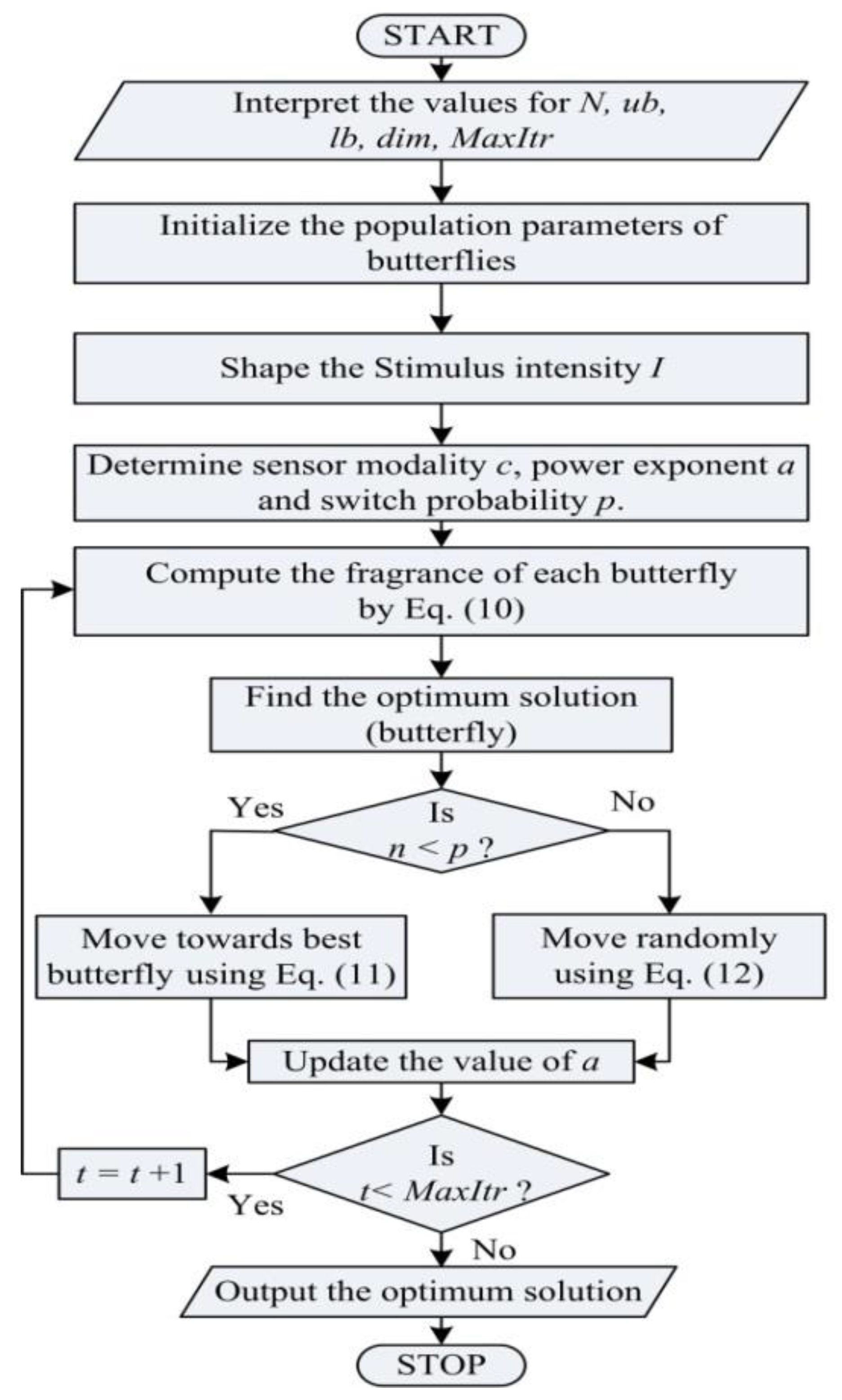
3.3. Overview of Butterfly Optimization Algorithm (BOA)

In the VPP model, generating units are employed with the controllers (PI/PID). The parameters of these controllers are optimized using GA, PSO, SSA, and the recently developed BOA. GA, PSO, and SSA are detailed in references [23,24,25], respectively, so the authors present only BOA in the present paper.
Recently, in 2018, Arora and Singh developed a Butterfly Optimization algorithm (BOA) by utilizing the food searching strategy and mating behavior of butterflies [26]. The optimization function considers butterflies as search agents [39]. The entire conception of sensing and processing the modality depends on three important factors viz. sensory modality ‘c’, stimulus intensity ‘I’, and power exponent ‘a’. The sensory modality is fragrance, ‘I’ is the magnitude of the physical stimulus and the parameter ‘a’ allows for regular expression, linear response, and response compression in BOA. Using these concepts, in BOA, the fragrance is formulated as a function of the physical intensity of stimulus as follows:
f = c I a ,
where ‘f’ is the perceived magnitude of the fragrance, i.e., how much stronger the fragrance is perceived by other butterflies. We can consider ‘a’ and ‘c’ in the range [0, 1] for our study. The algorithm has two key steps, viz., global search phase and local search phase. In global search phase, the butterfly takes a step toward the fittest butterfly/solution ‘g’, which is represented by the following equation:
x i t + 1 = x i t + ( r 2 × x j t x k t ) × f i ,
where x i t is the solution vector xi for ith butterfly in iteration number ‘t’. Here, g represents the current best solution found among all the solutions in current iteration. Fragrance of ith butterfly is represented by fi and r is a random number in [0, 1].
Local search phase can be represented as:
x i t + 1 = x i t + ( r 2 × g x i t ) × f i ,
where x j t and x k t are jth and kth butterflies from the solution space. If x j t and x k t belong to the same swarm and r is a random number in [0, 1], then Equation (12) becomes a local random walk. The corresponding flow diagram of BOA technique is displayed in Figure 3. The considered system parameters are tabulated in the Appendix A.

4. Simulated Results and Analysis

In order to investigate the system response, the proposed system shown in Figure 2 was modeled and simulated in MATLAB. System conditions detailed in Table 2 were enforced and three different optimization techniques were utilized to benchmark their performances.

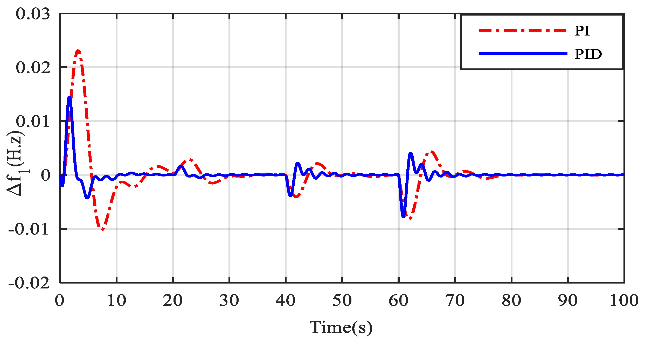
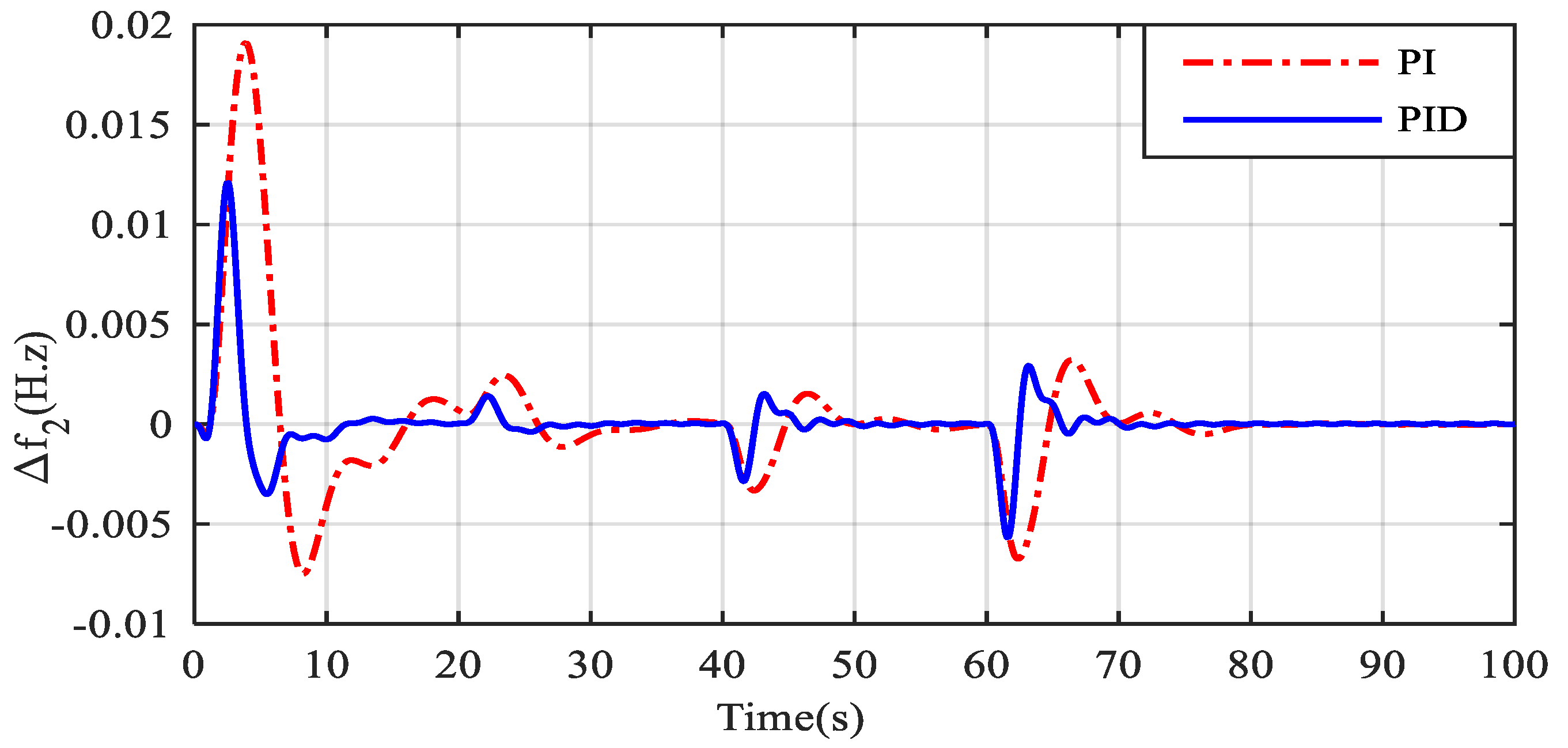
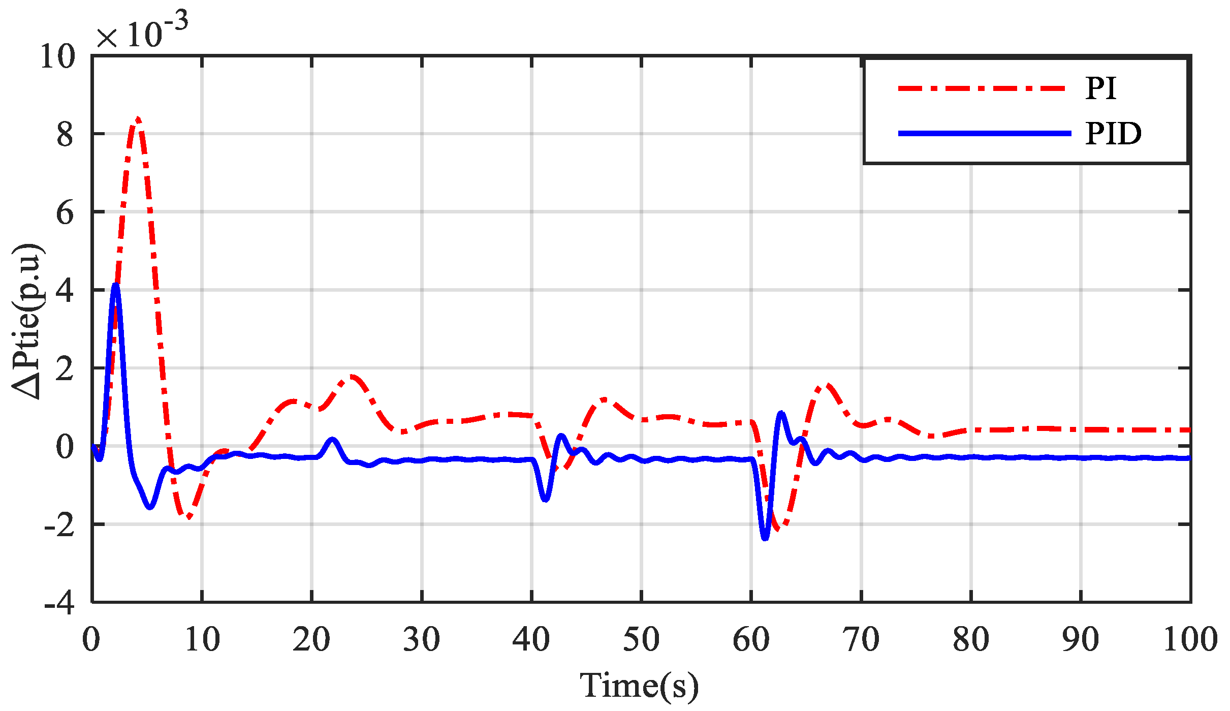
4.1. Time Domain Analysis of the VPP Model Employed with PI and PID

The time domain analysis obtained by simulation of the MATLAB Simulink model (Figure 2) is shown in Figure 4, Figure 5 and Figure 6. Controller parameters in this case were optimized using particle swarm optimization algorithms (PSO). From the responses Δf1, Δf2, and ΔPtie, as presented in Table 3, it was observed that the PI controlled system has higher overshoot, under-shoot, and settling time as compared to the PID controlled system. Because of the derivative term in PID controller, it acts faster to the system disturbance in the VPP and the EMS system sets the appropriate coordination between the DERS to cater the demand, which in turn contains frequency fluctuation.

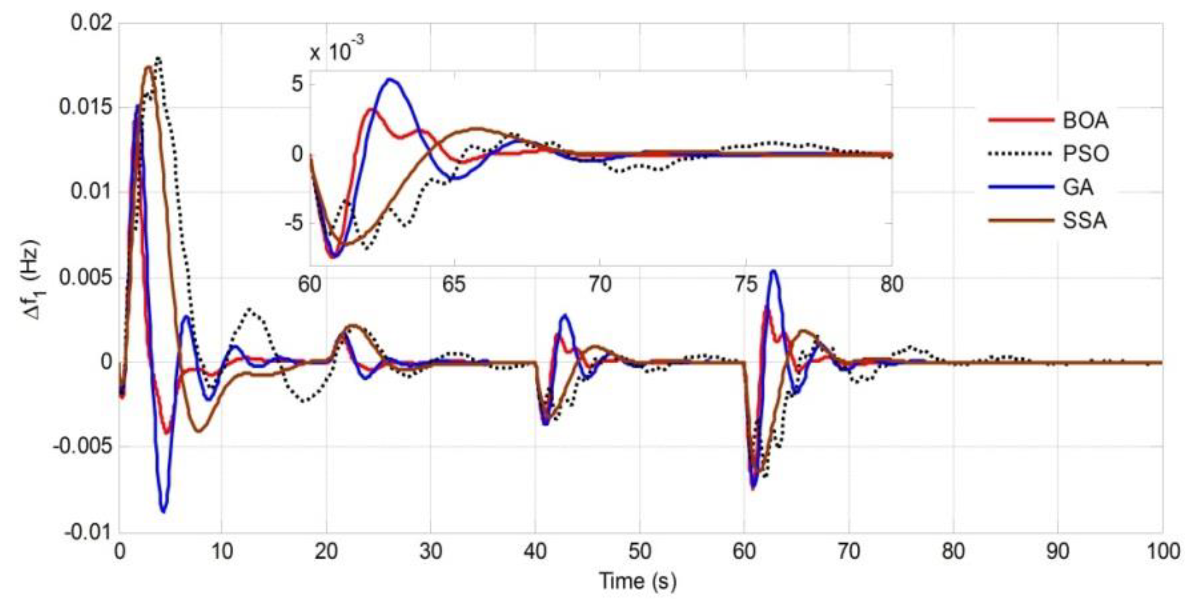
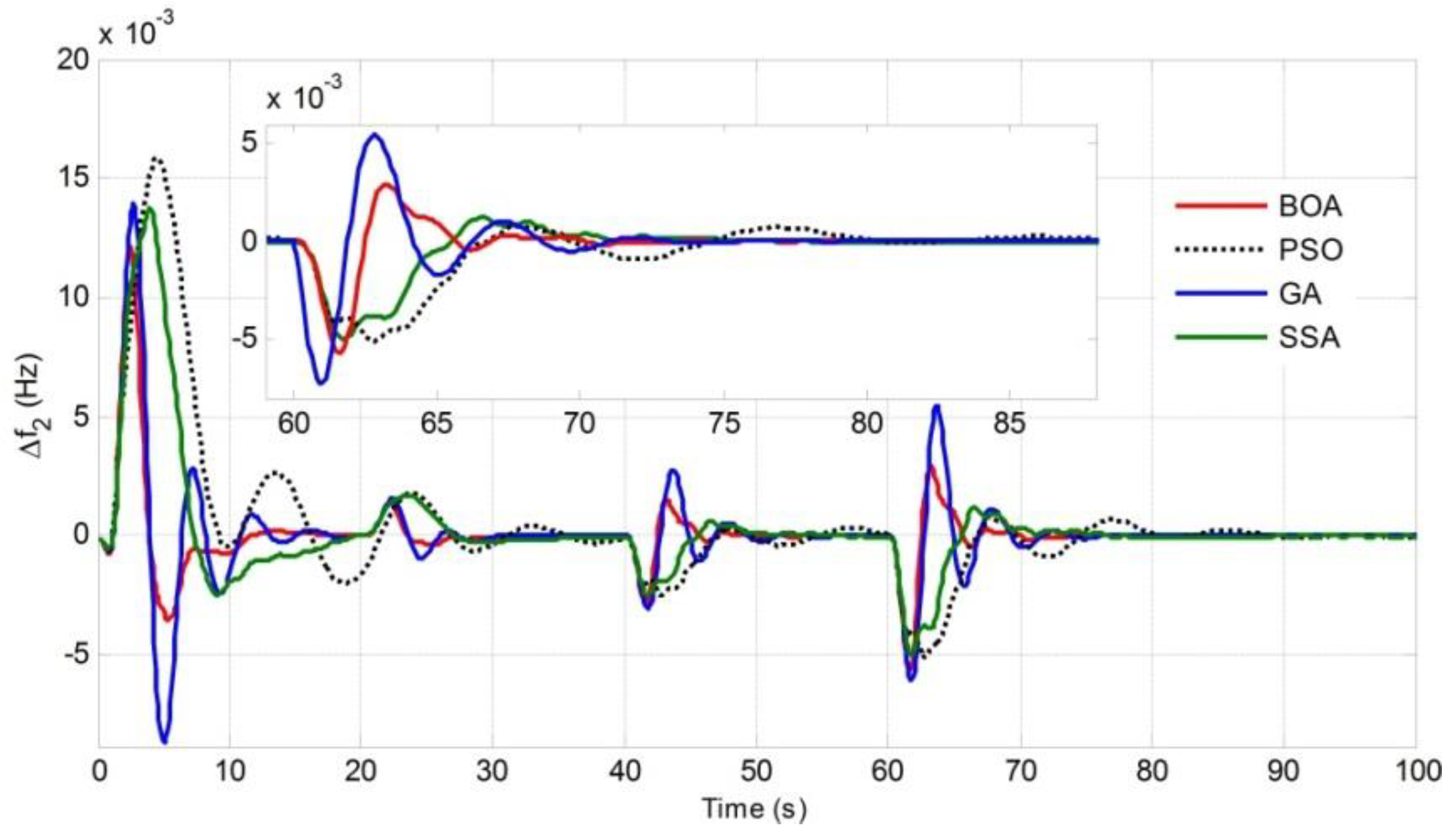
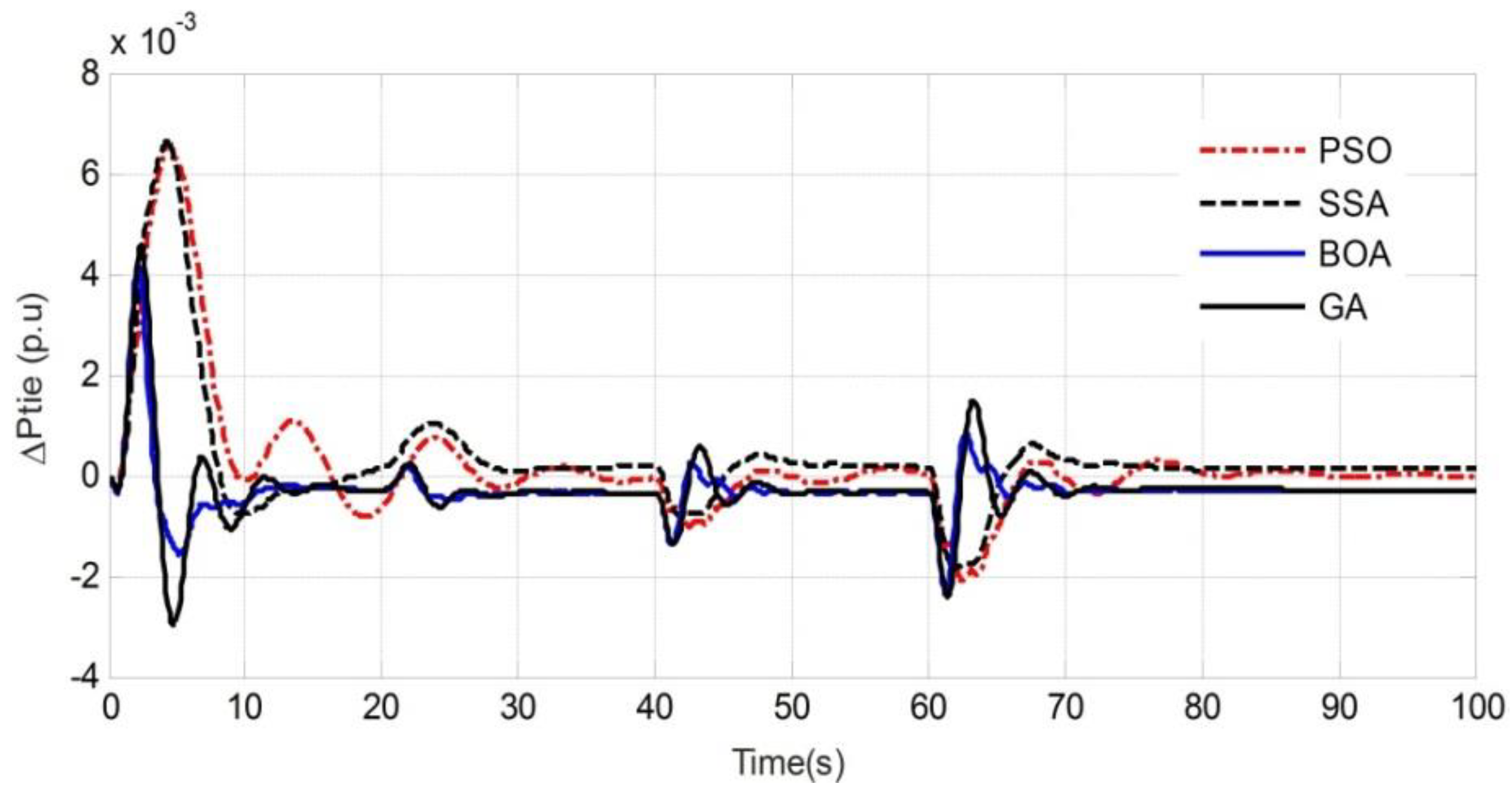
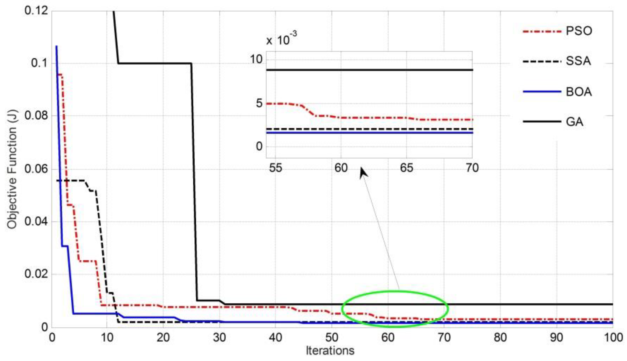
4.2. Time Domain Analysis for Optimization Algorithms GA, PSO, SSA, and BOA

The time domain analyses in Figure 7, Figure 8 and Figure 9 were obtained by PID controller-based simulation of the proposed MATLAB Simulink VPP model using optimization algorithms PSO, SSA, and BOA. The responses of Δf1, Δf2, and ΔPtie using GA, PSO, SSA, and BOA are illustrated, which show that the response in the case of BAO was better than GA, PSO, and SSA at all the times when changes occurred frequently in the system. It can be clearly seen from Table 4 that in the case of GA, PSO, and SSA, the overshoot, under-shoot, and settling time were more when the system was getting disturbed, but in the case of BOA, it showed better control over system controller parameters.
This analysis interpreted that BOA-optimized PID controllers give a better result than the GA, PSO, and SSA optimized counterparts and illustrated the superiority of BOA over the GA, PSO, and SSA algorithms. Furthermore, the convergence curves of GA, PSO, SSA, and BOA as shown in Figure 10 also confirm the superiority of BOA over GA, PSO, and SSA.

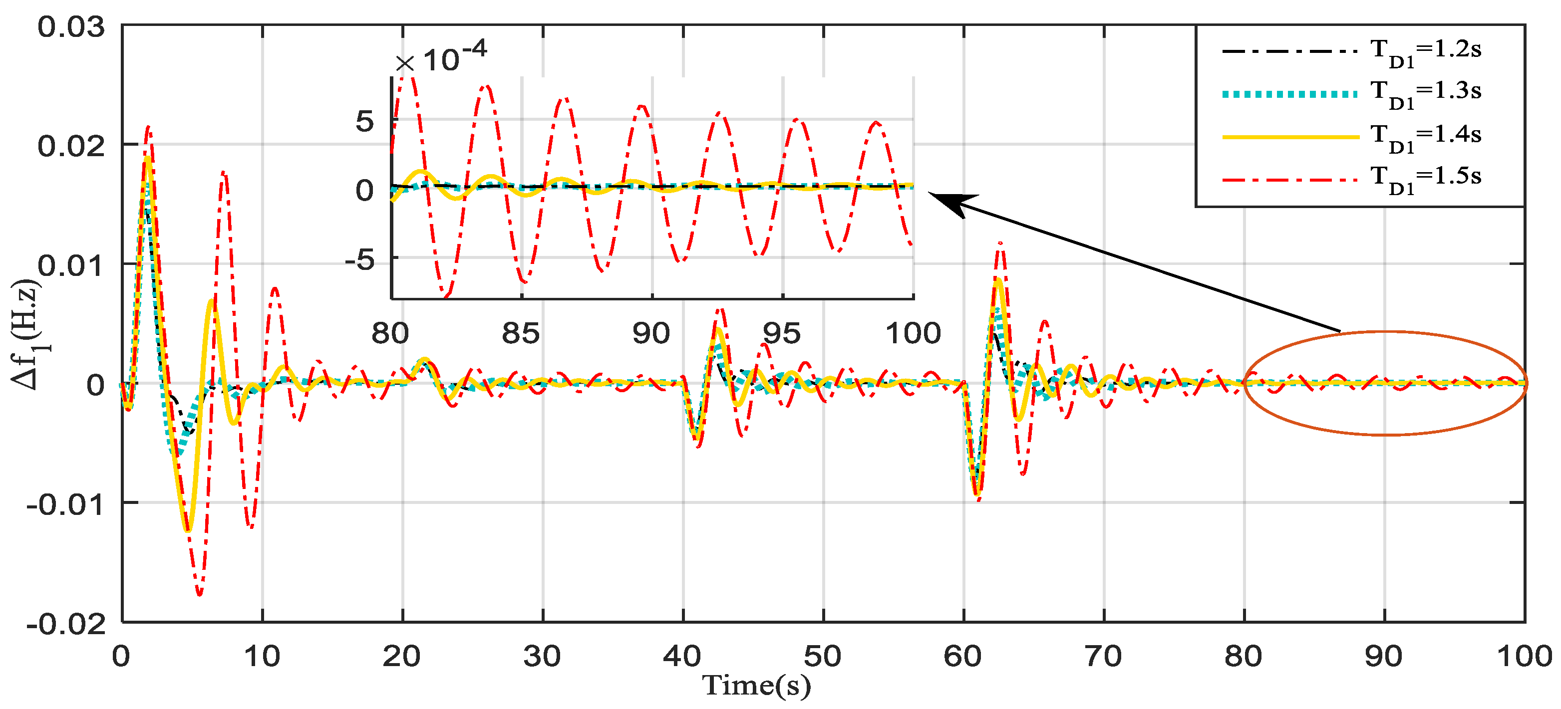
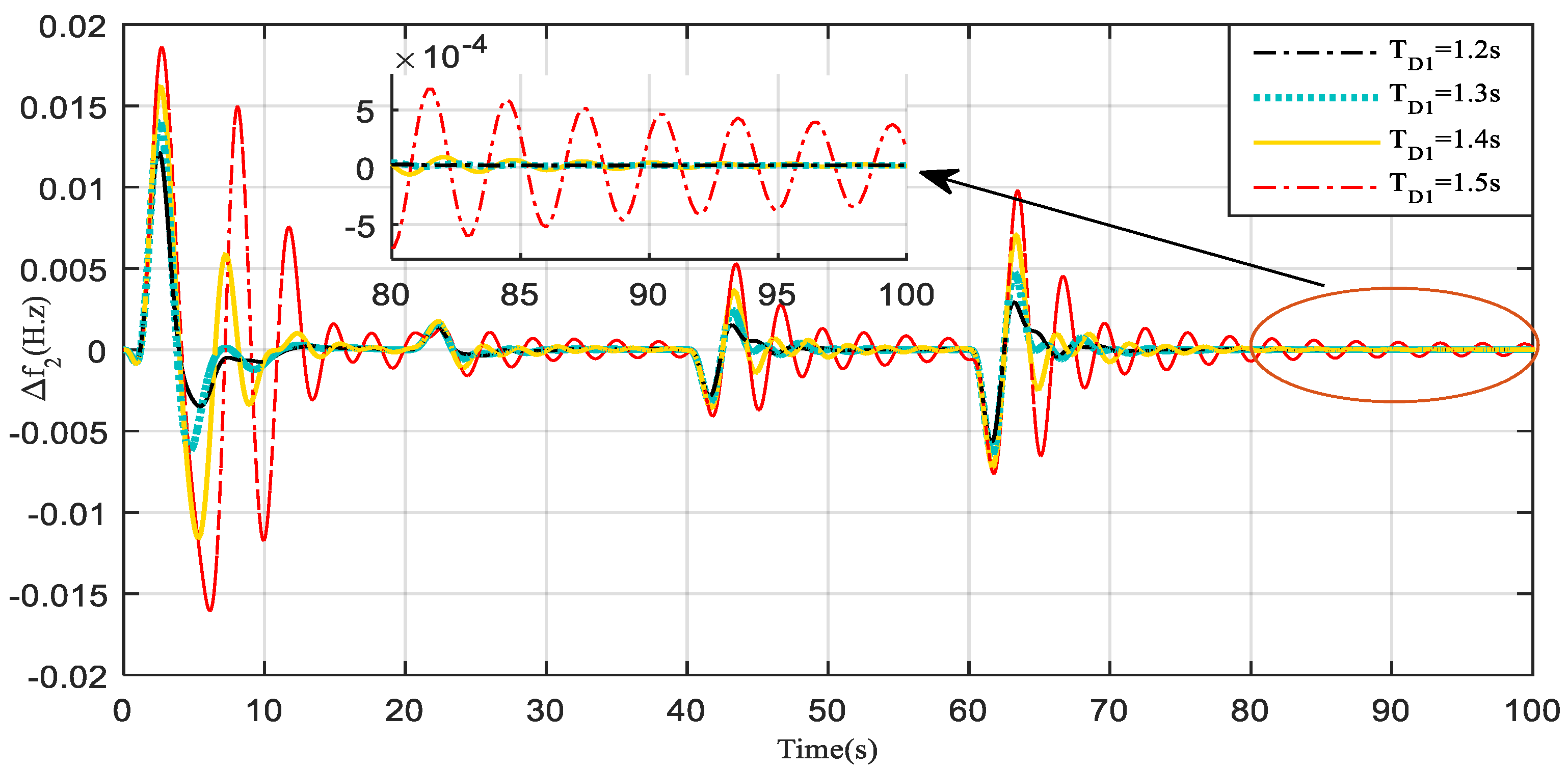
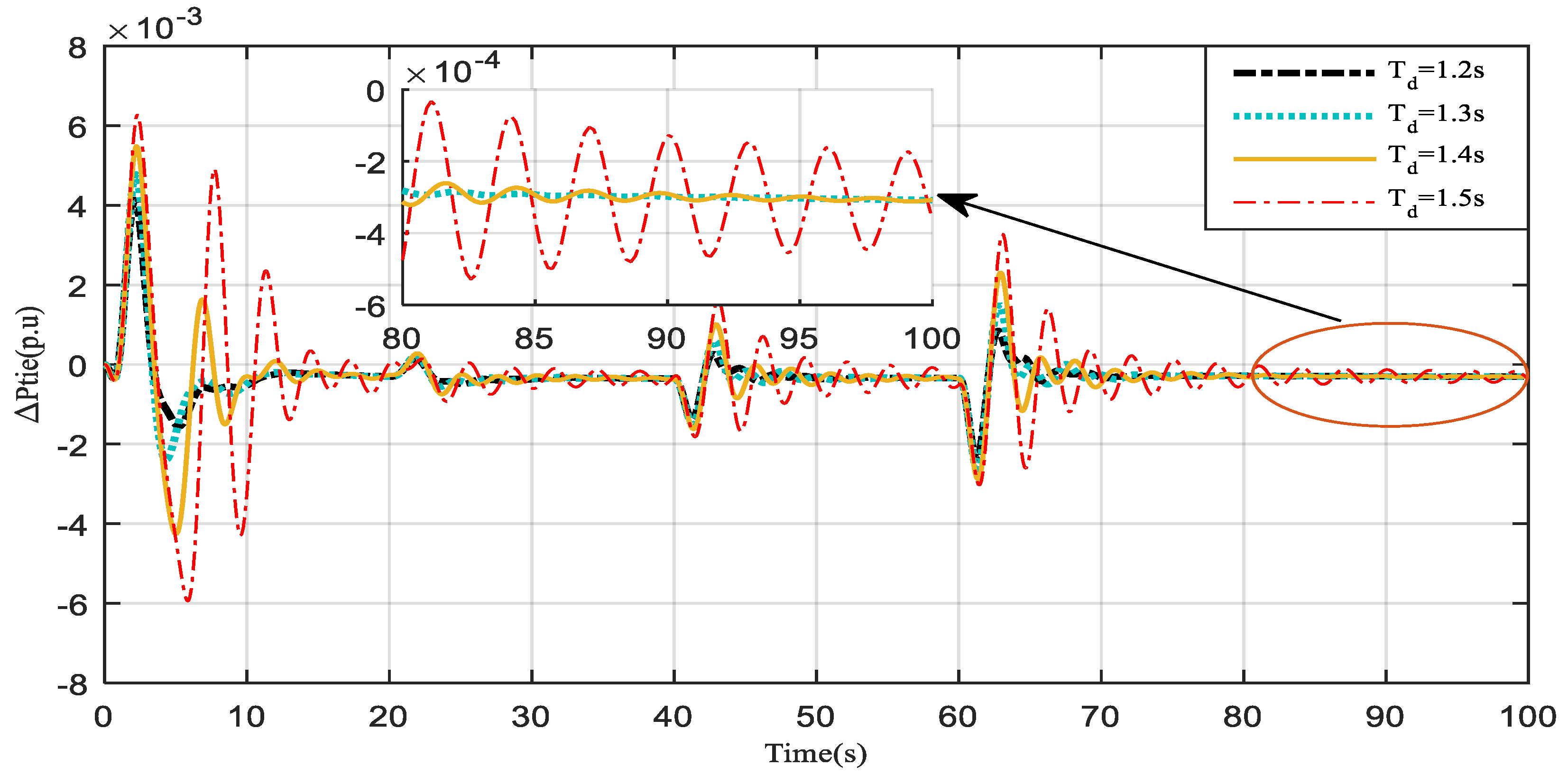
4.3. Time Domain Analysis of the VPP Model with Increasing Communication Delay (TD)

The system stability is significantly influenced by communication delay, TD. If the communication delay in a VPP exceeds a threshold value, it causes oscillations, and in the worst case may lead to instability. This section presents the comparative performance of the proposed MATLAB Simulink VPP model with increasing TD1. Figure 11, Figure 12 and Figure 13 represent Δf1, Δf2, and ΔPtie, respectively, for a BOA-optimized PID controller for the proposed VPP model. The analysis of response for Δf1, Δf2, and ΔPtie, in terms of the peak overshoot, peak under-shoot, and settling time reveal that as the time delay was increased from TD1 = 1.2 s to TD1 = 1.4 s stepwise (with a step of 0.1 s) system oscillation was also increased. However, the proposed control scheme regulates the system frequency deviations. The moment TD1 increases to 1.5 s, the system oscillation increased significantly as compared to that of the oscillation occurred at 1.2 s and the system seems to be on the verge of losing stability. Hence, TD1 = 1.4 s could be considered as the threshold value of communication time delay and any value beyond this would impede the stable operation of the VPP. The Table 5 provides a quantitative representation of the increased system oscillations with the increase in the communication time delay in the system.

5. Conclusions

Dynamic control that is based on the VPP concept can enhance system dynamics of power systems. This may lead to an increase in the share of renewable energy, while improving the transmission efficiency and reliability at the same time. The present work investigated the capability of using VPP to regulate the grid frequency with high penetration of CRSTS, WTG, and EV. Furthermore, the effect of real-time communication delays in VPP operation were also considered and incorporated in the system design.
The proposed grid-integrated VPP model was developed in the MATLAB Simulation platform and the impact with communication delays on the performance of the frequency regulation of VPP was evaluated. Simulation results show that increased communication delay can significantly degrade the response and even make the system unstable in some cases. Communication time delay of 1.4 s was found to be acceptable and hence considered as the threshold value for the proposed model. Any value beyond this would impede the stable operation of the VPP. On the control strategy, the analysis of the results endorses the superiority of the PID over PI controller and also establishes the dominance of the new optimization tool, i.e., BOA, over GA, PSO, and SSA. Finally, it has been observed that the available control strategy on interconnected microgrid could be employed for active power regulation of grid-integrated VPP in modified form, incorporating the real-time communication delays. In our future work we shall consider application of other controller, like fractional order PID controller in VPP control strategy.

Author Contributions

Conceptualization, P.P.D.; A.L., S.M.S.H., D.C.D. and T.S.U.; Methodology, P.P.D.; A.L., S.M.S.H., D.C.D. and T.S.U.; Software, P.P.D. and A.L.; Validation, P.P.D.; D.C.D. and A.L.; Formal Analysis, A.L., S.M.S.H., D.C.D. and T.S.U.; Writing—Original Draft Preparation, P.P.D.; A.L. and D.C.D.; Writing—Review and Editing, S.M.S.H., and T.S.U.; Visualization, P.P.D. and A.L.; Supervision, D.C.D.; Funding Acquisition, T.S.U. All authors have read and agreed to the published version of the manuscript.

Funding

This research received no external funding.

Acknowledgments

Authors would like to thank TEQIP-III NIT Silchar for providing technical support for this work.

Conflicts of Interest

The authors declare no conflict of interest.

Abbreviations

REsRenewable energies
VPPVirtual power plant
CRSTSCentral receiver solar thermal system
WTGWind turbine generator
EVElectric vehicle
GAGenetic algorithm
PSOParticle swarm optimization
SSASlap swarm algorithm
BOAButterfly optimization algorithm
DERsDistributed energy resources
ICTInformation and communication technology
EMSEnergy management system
ESSEnergy storage system
PIDProportional integral derivative
TDCommunication time delay
ISEIntegral of the square error

Appendix A

Butterfly technique: Number of search agents: 50, Total iterations: 100, Probability of switching = 0.8, Power component = 0.1, Sensor modality = 0.1.
Salp swarm technique: Number of search agents: 50, Total iterations: 100.
Particle swarm technique: Number of search agents: 50, Total iterations: 100, Weighting factors (Wmax, Wmin) = 0.9 and 0.1, C1 = 2, C2 = 2.
Genetic algorithm: Number of nests: 50, Total iterations: 100, Probability of crossover = 0.8, Probability of mutation = 0.01.

References

  1. Strasser, T.; Andren, F.; Kathan, J.; Cecati, C.; Buccella, C.; Siano, P.; Leitão, P.; Zhabelova, G.; Vyatkin, V.; Vrba, P.; et al. A Review of Architectures and Concepts for Intelligence in Future Electric Energy Systems. IEEE Trans. Ind. Electron. 2014, 62, 2424–2438. [Google Scholar] [CrossRef] [Green Version]
  2. Xin, H.; Gan, D.; Li, N.; Li, H.; Dai, C. Virtual power plant-based distributed control strategy for multiple distributed generators. IET Control Theory Appl. 2012, 7, 90–98. [Google Scholar] [CrossRef] [Green Version]
  3. Praveen, R.P. Performance Analysis and Optimization of Central Receiver Solar Thermal Power Plants for Utility Scale Power Generation. Sustainability 2020, 12, 127. [Google Scholar]
  4. Niñerola, A.; Ferrer-Rullan, R.; Vidal-Suñé, A. Climate Change Mitigation: Application of Management Production Philosophies for Energy Saving in Industrial Processes. Sustainability 2020, 12, 717. [Google Scholar] [CrossRef] [Green Version]
  5. Du, E.; Zhang, N.; Hodge, B.M.; Wang, Q.; Kang, C.; Kroposki, B.; Xia, Q. The role of concentrating solar power toward high renewable energy penetrated power systems. IEEE Trans. Power Syst. 2018, 33, 6630–6641. [Google Scholar] [CrossRef]
  6. Ho, C.K. Advances in central receivers for concentrating solar applications. Sol. Energy 2017, 152, 38–56. [Google Scholar] [CrossRef]
  7. Nadeem, F.; Aftab, M.A.; Hussain, S.M.; Ali, I.; Tiwari, P.K.; Goswami, A.K.; Ustun, T.S. Virtual Power Plant Management in Smart Grids with XMPP Based IEC 61850 Communication. Energies 2019, 12, 2398. [Google Scholar] [CrossRef] [Green Version]
  8. Yavuz, L.; Önen, A.; Muyeen, S.M.; Kamwa, I. Transformation of microgrid to virtual power plant—A comprehensive review. IET Gener. Transm. Distrib. 2019, 13, 1994–2005. [Google Scholar] [CrossRef]
  9. Castillo, A.; Flicker, J.; Hansen, C.W.; Watson, J.P.; Johnson, J. Stochastic Optimization with Risk Aversion for Virtual Power Plant Operations: A Rolling Horizon Control. IET Gener. Transm. Distrib. 2018, 13, 2063–2067. [Google Scholar] [CrossRef]
  10. Ramos, L.F.; Canha, L.N. Virtual Power Plants and Their Prospects. Electr. Electron. Eng. 2019, 1–21. [Google Scholar] [CrossRef]
  11. Zajc, M.; Kolenc, M.; Suljanović, N. Virtual power plant communication system architecture. In Smart Power Distribution Systems Control, Communication, and Optimization; Academic Press: London, UK, 2018; pp. 231–250. [Google Scholar]
  12. Khorasany, M.; Azuatalam, D.; Glasgow, R.; Liebman, A.; Razzaghi, R. Transactive Energy Market for Energy Management in Microgrids: The Monash Microgrid Case Study. Energies 2020, 13, 2010. [Google Scholar] [CrossRef]
  13. Obaid, Z.A.; Cipcigan, L.M.; Abrahim, L.; Muhssin, M.T. Frequency control of future power systems: Reviewing and evaluating challenges and new control methods. J. Mod. Power Syst. Clean Energy 2018, 7, 9–25. [Google Scholar] [CrossRef]
  14. Abbasi, E. Coordinated primary control reserve by flexible demand and wind power through ancillary service–centered virtual power plant. Int. Trans. Electr. Energy Syst. 2017, 27, e2452. [Google Scholar] [CrossRef]
  15. Tavakkoli, M.; Adabi, J.; Zabihi, S.; Godina, R.; Pouresmaeil, E. Reserve Allocation of Photovoltaic Systems to Improve Frequency Stability in Hybrid Power Systems. Energies 2018, 11, 2583. [Google Scholar] [CrossRef] [Green Version]
  16. Liu, Y.; Xin, H.; Wang, Z.; Gan, D. Control of virtual power plant in microgrids: A coordinated approach based on photovoltaic systems and controllable loads. IET Gener. Transm. Distrib. 2015, 9, 921–928. [Google Scholar] [CrossRef] [Green Version]
  17. Pudjianto, D.; Ramsay, C.; Strbac, G. Virtual power plant and system integration of distributed energy resources. IET Renew. Power Gener. 2007, 1, 10–16. [Google Scholar] [CrossRef]
  18. Vandoorn, T.L.; Zwaenepoel, B.; De Kooning, J.D.; Meersman, B.; Vandevelde, L. Smart microgrids and virtual power plants in a hierarchical control structure. In Proceedings of the 2011 2nd IEEE PES International Conference and Exhibition on Innovative Smart Grid Technologies, Manchester, UK, 5–7 December 2011; pp. 1–7. [Google Scholar]
  19. Newman, G.; Mutale, J. Characterising Virtual Power Plants. Int. J. Electr. Eng. Educ. 2019, 4, 307–318. [Google Scholar] [CrossRef]
  20. Ruiz, N.; Cobelo, I.; Oyarzabal, J. A direct load control model for virtual power plant management. IEEE Trans. Power Syst. 2009, 24, 959–966. [Google Scholar] [CrossRef]
  21. Javaid, C.J.; Allahham, A.; Giaouris, D.; Blake, S.; Taylor, P. Modelling of a virtual power plant using hybrid automata. In Proceedings of the 9th International Conference on Power Electronics, Machines and Drives (PEMD 2018), Liverpool, UK, 17–19 April 2018; pp. 3918–3922. [Google Scholar]
  22. Wu, H.; Ni, H.; Heydt, G.T. The Impact of Time Delay on Robust Control Design in Power Systems. In Proceedings of the IEEE Power Engineering Society Winter Meeting, New York, NY, USA, 27–31 January 2002. [Google Scholar]
  23. Ranjan, S.; Das, D.C.; Behera, S.; Sinha, N. Parabolic trough solar–thermal–wind–diesel isolated hybrid power system: Active power/ frequency control analysis. IET Renew. Power Gener. 2018, 12, 1893–1903. [Google Scholar] [CrossRef]
  24. Kennedy, J.; Eberhart, R. Particle Swarm Optimization; Purdue School of Engineering and Technology: Indianapolis, IN, USA, 1995; pp. 1–7. [Google Scholar]
  25. Mirjalili, S.; Gandomi, A.H.; Mirjalili, S.Z.; Saremi, S.; Faris, H.; Mirjalili, S.M. Salp Swarm Algorithm: A bio-inspired optimizer for engineering design problems. Adv. Eng. Softw. 2017, 114, 163–191. [Google Scholar] [CrossRef]
  26. Arora, S.; Singh, S. Butterfly optimization algorithm: A novel approach for global optimization. Soft Comput. 2019, 23, 715–734. [Google Scholar] [CrossRef]
  27. Tungadio, D.H.; Bansal, R.C.; Siti, M.W. Optimal control of active power of two micro-grids interconnected with two AC tie-lines. Electr. Power Compon. Syst. 2017, 45, 2188–2199. [Google Scholar] [CrossRef]
  28. Lal, D.K.; Barisal, A.K.; Tripathy, M. Load Frequency Control of Multi Area Interconnected Microgrid Power System using Grasshopper Optimization Algorithm Optimized Fuzzy PID Controller. In Proceedings of the 2018 Recent Advances on Engineering, Technology and Computational Sciences (RAETCS), Allahabad, India, 6–8 February 2018; pp. 1–6. [Google Scholar]
  29. Ei-Fergany, A.A.; Ei-Hameed, A.M. Efficient frequency controllers for autonomous two-area hybrid microgrid system using social-spider optimizer. IET Gener. Transm. Distrib. 2017, 11, 637–648. [Google Scholar] [CrossRef]
  30. Bhuyan, M.; Barik, A.K.; Das, D.C. GOA optimised frequency control of solar-thermal/sea-wave/biodiesel generator based interconnected hybrid microgrids with DC link. Int. J. Sustain. Energy 2020, 39, 615–633. [Google Scholar] [CrossRef]
  31. Wang, X.; Zhao, Q.; He, B.; Wang, Y.; Yang, J.; Pan, X. Load frequency control in multiple microgrids based on model predictive control with communication delay. J. Eng. 2017, 2017, 1851–1856. [Google Scholar] [CrossRef]
  32. Global Review of Solar Tower Technology. August 2014. Available online: http://www.seriius.org/pdfs/global-review-solar-tower-technology.pdf (accessed on 26 August 2020).
  33. Cerecedo, L.O.L.; Pitalua-Diaz, N.; Transito, I.S.; Contreras, L.E.V.; Bulnes, C.A. Optical performance modeling of a solar tower heliostat field and Estimation of receiver temperature. In Proceedings of the 2013 IEEE International Autumn Meeting on PE and computing, Mexico City, Mexico, 13–15 November 2013; pp. 1–6. [Google Scholar]
  34. Latif, A.; Das, D.C.; Barik, A.K.; Ranjan, S. Maiden co-ordinated load frequency control strategy for ST-AWEC-GEC-BDDG based independent three-area interconnected microgrid system with combined effect of diverse energy storage and DC link using BOA optimized PFOID controller. IET Renew. Power Gener. 2019, 10, 2634–2646. [Google Scholar] [CrossRef]
  35. Tehrani, K. A smart cyber physical multi-source energy system for an electric vehicle prototype. J. Syst. Archit. 2020, 111, 101804. [Google Scholar] [CrossRef]
  36. Bendjedia, M.; Tehrani, K.A.; Azzouz, Y. Design of RST and fractional order PID controllers for an induction motor drive for electric vehicle application. In Proceedings of the 7th IET International Conference on Power Electronics, Machines and Drives (PEMD 2014), Manchester, UK, 8–10 April 2014; pp. 1–8. [Google Scholar]
  37. Khezri, R.; Oshnoei, A.; Hagh, M.T.; Muyeen, S.M. Coordination of Heat Pumps, Electric Vehicles and AGC for Efficient LFC in a Smart Hybrid Power System via SCA-Based Optimized FOPID Controllers. Energies 2018, 11, 420. [Google Scholar] [CrossRef] [Green Version]
  38. Singh, V.P.; Samuel, P.; Kishor, N. Effect of Communication Delay on Load Frequency Control Application in Autonomous Hybrid Power System. In Proceedings of the 2015 IEEE Innovative Smart Grid Technologies, Bangkok, Thailand, 3–6 November 2015; pp. 1–6. [Google Scholar]
  39. Latif, A.; Hussain, S.M.S.; Das, D.C.; Ustun, T.S. Optimum Synthesis of a BOA Optimized Novel Dual-Stage PI − (1 + ID) Controller for Frequency Response of a Microgrid. Energies 2020, 13, 3446. [Google Scholar] [CrossRef]
Figure 1. Schematic of a central receiver solar thermal system (CRSTS) [33].
Sustainability 12 06979 g001
Figure 2. Schematic for Grid-Integrated VPP considering Communication Delay.
Sustainability 12 06979 g002
Figure 3. Flow diagram of the BOA technique.
Sustainability 12 06979 g003
Figure 4. Δf1 for PI and PID.
Sustainability 12 06979 g004
Figure 5. Δf2 for PI and PID.
Sustainability 12 06979 g005
Figure 6. ΔPtie for PI and PID.
Sustainability 12 06979 g006
Figure 7. Δf1 under GA, PSO, SSA, and BOA.
Sustainability 12 06979 g007
Figure 8. Δf2 under GA, PSO, SSA, and BOA.
Sustainability 12 06979 g008
Figure 9. ΔPtie under GA, PSO SSA, and BOA.
Sustainability 12 06979 g009
Figure 10. Comparative convergence curve under GA, PSO, SSA, and BOA.
Sustainability 12 06979 g010
Figure 11. Δf1 with increasing communication delay.
Sustainability 12 06979 g011
Figure 12. Δf2 with increasing communication delay.
Sustainability 12 06979 g012
Figure 13. ΔPtie with increasing communication delay.
Sustainability 12 06979 g013
Table 1. Nomenclature with considered systems’ symbols values [34].
NomenclatureValue
KRF, KRV, KG, KTGains of refocus, receiver, governor and turbine of CRSTS1, 1, 1, 1
TRF, TRV, TG, TTTime of refocus, receiver, governor, and turbine of CRSTS1.33 s, 4 s, 0.08 s, 1 s
KWTG, TWTGGain and time constant of WTG1, 1.5 s
KTd, TTdEV gain and time constant1, 0.15 s
TG1, TT1Gain and delay of conventional generator0.08, 0.3 s
R1, R2Constant droop value of area-1, 22.4 Hz/p.u MW
B1, B2Biasing constant of area-1, 20.429, 0.424
Ksys1, Ksys2System characteristics1120
M1&M2Moment of inertia of the VPP and Conventional Generator.0.2 s, 0.166 s
D1&D2Damping constant of the VPP and Conventional Generator.0.012, 0.008 (p.u MW/Hz)
TD1, TD2Communication delay for VPP and Conventional plant1.2 s, 1 s
T12Synchronizing tie-line co-efficient between area-1 and 24.397
Table 2. Operating conditions for an interconnected VPP system.
CaseSubsystemSimulation Time (s)Operating Condition
Case-1: for comparison between PI and PID controller performanceCRSTS, WTG, DEG, PHEV and load100PWTG = 0.1 p.u. at 0 < t < 20 s
  = 0.11 p.u. at t > 20 s
Pd1 = 0.02 p.u. at 0 < t < 40 s
  = 0.03 p.u. at 40 < t < 60 s
= 0.05 p.u. at t > 60 s
Communication time delay for Area-1 is TD1 = 1.2 s and for Area-2 is TD2 = 1 s
Case-2: for comparison of optimization algorithms GA, PSO, SSA and BOA
Case-3: for comparison of dynamic response with increased time delay attacks
Table 3. Peak over-shoot, under-shoot, and settling time for PI and PID controller parameters optimized using PSO.
Case-1ResponsePeak over Shoot (H.z)Peak Under-Shoot (H.z)Settling Time (s)
PIΔf10.040190.0114990.00
Δf20.038820.0110189.36
ΔPtie0.016350.0045989.58
PIDΔf10.017960.00650983.65
Δf20.01590.00461682.74
ΔPtie0.006580.00201981.04
Table 4. Peak over-shoot, under-shoot, and settling times for PID controller parameters optimized using GA, PSO, SSA, and BOA.
Case-3ResponsePeak over Shoot (H.z)Peak Under-Shoot (H.z)Settling Time (s)
GAΔf10.014980.0090872.11
Δf20.014050.0091274.24
ΔPtie0.004270.0030973.85
PSOΔf10.017960.00650983.65
Δf20.015900.00461682.74
ΔPtie0.006580.00201981.04
SSAΔf10.017300.00630675.74
Δf20.013940.0052875.54
ΔPtie0.006620.0017675.25
BOAΔf10.014280.0075770.30
Δf20.012170.0056172.02
ΔPtie0.0041530.0023972.60
Table 5. Peak over-shoot, under-shoot, and settling time for BOA-optimized PID controller considering different time delays.
Time Delay AttacksResponsePeak over Shoot (Hz)Peak Under-Shoot (Hz)Settling Time (s)
TD1 = 1.2 sΔf10.014280.0075770.30
Δf20.012170.0056172.02
ΔPtie0.0041530.0023972.60
TD1 = 1.3 sΔf10.016390.0085774.6
Δf20.013970.0063973.19
ΔPtie0.004770.0024775.62
TD1 = 1.4 sΔf10.018940.012280.20
Δf20.016160.0113780.10
ΔPtie0.005420.0040880.26
TD1 = 1.5 sΔf10.021340.01738Unsettled
Δf20.018640.01602Unsettled
ΔPtie0.006220.00561Unsettled

